EP1004201B1 - Channel changer for use in a switched digital video system - Google Patents
Channel changer for use in a switched digital video system Download PDFInfo
- Publication number
- EP1004201B1 EP1004201B1 EP98931769A EP98931769A EP1004201B1 EP 1004201 B1 EP1004201 B1 EP 1004201B1 EP 98931769 A EP98931769 A EP 98931769A EP 98931769 A EP98931769 A EP 98931769A EP 1004201 B1 EP1004201 B1 EP 1004201B1
- Authority
- EP
- European Patent Office
- Prior art keywords
- channel
- video
- subscriber
- video data
- group
- Prior art date
- Legal status (The legal status is an assumption and is not a legal conclusion. Google has not performed a legal analysis and makes no representation as to the accuracy of the status listed.)
- Expired - Lifetime
Links
- 239000000872 buffer Substances 0.000 claims description 29
- 238000000034 method Methods 0.000 claims description 12
- 230000005540 biological transmission Effects 0.000 claims description 11
- 239000013307 optical fiber Substances 0.000 claims description 7
- 238000011144 upstream manufacturing Methods 0.000 description 6
- 230000006835 compression Effects 0.000 description 5
- 238000007906 compression Methods 0.000 description 5
- 238000005516 engineering process Methods 0.000 description 5
- 238000012508 change request Methods 0.000 description 4
- 238000012790 confirmation Methods 0.000 description 3
- 239000000835 fiber Substances 0.000 description 2
- 230000003287 optical effect Effects 0.000 description 2
- 230000011664 signaling Effects 0.000 description 2
- 238000012546 transfer Methods 0.000 description 2
- 230000002457 bidirectional effect Effects 0.000 description 1
- 238000004891 communication Methods 0.000 description 1
- 238000010276 construction Methods 0.000 description 1
- 230000001934 delay Effects 0.000 description 1
- 238000011161 development Methods 0.000 description 1
- 230000018109 developmental process Effects 0.000 description 1
- 230000009977 dual effect Effects 0.000 description 1
- 230000000694 effects Effects 0.000 description 1
- 238000009434 installation Methods 0.000 description 1
- 230000002452 interceptive effect Effects 0.000 description 1
- 238000007726 management method Methods 0.000 description 1
- 239000000203 mixture Substances 0.000 description 1
- 238000012986 modification Methods 0.000 description 1
- 230000004048 modification Effects 0.000 description 1
- 238000012163 sequencing technique Methods 0.000 description 1
- 230000008054 signal transmission Effects 0.000 description 1
- 230000001360 synchronised effect Effects 0.000 description 1
Images

Classifications
-
- H—ELECTRICITY
- H04—ELECTRIC COMMUNICATION TECHNIQUE
- H04N—PICTORIAL COMMUNICATION, e.g. TELEVISION
- H04N21/00—Selective content distribution, e.g. interactive television or video on demand [VOD]
- H04N21/40—Client devices specifically adapted for the reception of or interaction with content, e.g. set-top-box [STB]; Operations thereof
- H04N21/41—Structure of client; Structure of client peripherals
- H04N21/426—Internal components of the client ; Characteristics thereof
-
- H—ELECTRICITY
- H04—ELECTRIC COMMUNICATION TECHNIQUE
- H04N—PICTORIAL COMMUNICATION, e.g. TELEVISION
- H04N21/00—Selective content distribution, e.g. interactive television or video on demand [VOD]
- H04N21/40—Client devices specifically adapted for the reception of or interaction with content, e.g. set-top-box [STB]; Operations thereof
- H04N21/43—Processing of content or additional data, e.g. demultiplexing additional data from a digital video stream; Elementary client operations, e.g. monitoring of home network or synchronising decoder's clock; Client middleware
- H04N21/438—Interfacing the downstream path of the transmission network originating from a server, e.g. retrieving MPEG packets from an IP network
- H04N21/4383—Accessing a communication channel
- H04N21/4384—Accessing a communication channel involving operations to reduce the access time, e.g. fast-tuning for reducing channel switching latency
-
- H—ELECTRICITY
- H04—ELECTRIC COMMUNICATION TECHNIQUE
- H04N—PICTORIAL COMMUNICATION, e.g. TELEVISION
- H04N5/00—Details of television systems
- H04N5/44—Receiver circuitry for the reception of television signals according to analogue transmission standards
- H04N5/50—Tuning indicators; Automatic tuning control
-
- H—ELECTRICITY
- H04—ELECTRIC COMMUNICATION TECHNIQUE
- H04N—PICTORIAL COMMUNICATION, e.g. TELEVISION
- H04N7/00—Television systems
- H04N7/16—Analogue secrecy systems; Analogue subscription systems
-
- H—ELECTRICITY
- H04—ELECTRIC COMMUNICATION TECHNIQUE
- H04N—PICTORIAL COMMUNICATION, e.g. TELEVISION
- H04N7/00—Television systems
- H04N7/16—Analogue secrecy systems; Analogue subscription systems
- H04N7/173—Analogue secrecy systems; Analogue subscription systems with two-way working, e.g. subscriber sending a programme selection signal
- H04N7/17309—Transmission or handling of upstream communications
- H04N7/17336—Handling of requests in head-ends
Definitions
- the present invention relates generally to an apparatus for the distribution and delivery of video in a digital system and, in particular, to a method and apparatus that rapidly changes the channel in such a system.
- the cable television providers In order to ensure that each subscriber receives only the channels for which he has paid, the cable television providers encrypt or "scramble" the premium channels (HBO, CINEMAX, DISNEY, etc.). The cable television providers also may scramble many of the "basic" channels (local stations, ESPN, MTV, VH1, TNT, DISCOVERY, etc.). Therefore, even though virtually all television sets sold today are cable-ready, most subscribers still need a set-top unit (sometimes referred to as a cable box in the cable television environment) to descramble the signals. The set-top units are located proximate a television and are also used to change the channel that is viewed on the television.
- Switched video for viewing on a subscriber's television and high-speed Internet access are two services highly desired by subscribers.
- the new services will likely have to be capable of handling digital signals.
- a typical digital video delivery system includes a means for receiving the video signals from various broadcast sources, a means for delivering the signals to a plurality of subscribers, and a means of transmitting the signals between the receiving means and delivering means.
- the means for receiving the video signals may include a broadband digital terminal (BDT) located in a central office.
- the delivering means may be a broadband network unit (BNU) located preferably on a telephone pole or other convenient location proximate a number of subscribers. Cable or optical fiber connects the BDT to the BNU.
- a second cable (or a twisted wire pair) connects the set-top units (and, if required, the various other units in the subscriber's home) with the BNU.
- the set-top unit In a typical digital video system, all of the video services offered by the video service company are again delivered to the set-top unit. When selecting a new channel, the set-top unit performs the actual switching and also descrambles the digital signals.
- a solution to the theft problem is to perform the channel switching "upstream" from the subscriber at a facility controlled by the video provider (in a digital system at the BDT, for example), and only delivering one channel at a time to the subscriber's set-top unit.
- Another advantage of moving the switching upstream is that the bandwidth requirements of the overall video delivery system are greatly reduced.
- a drawback of this system is that the subscriber experiences a time delay between the period of time it takes for the subscriber to select a channel and for the newly selected channel to be viewed on the television.
- the reason for this time delay is that the subscriber's request must first travel upstream to the BDT; next, the BDT must acknowledge the request, then synchronize and "lock on" to the desired video service; finally, the BDT must transmit the desired video service back downstream to the subscriber.
- the overall delay between each channel change can take over a second.
- a significant portion of the delay is caused by the time it takes for the video signal to synchronize. This portion accounts for about half of the overall delay (i.e., about a half second). Many subscribers find the delay in such video delivery systems annoying since they are accustomed to seeing the broadcast signal immediately after selecting a new channel. Most subscribers find that a one second delay is unacceptable, which would make such a system competitively unattractive.
- the present invention relates to a method and apparatus for rapidly changing the channel in a digital video delivery system.
- the rapid channel changer will be preferably located in the central office with the broadband digital terminal (BDT) and indexes the "start" or synchronization frame of each video channel received at the BDT.
- BDT broadband digital terminal
- Each digital video signal includes a synchronization frame.
- the subject channel changer captures the multiple compressed video signals and stores each signal in a cache buffer.
- a processor is used to index or "point to" the respective synchronization frames for each buffered signal.
- the processor can immediately access the requested video signal at a synchronization frame and direct the video stream to the subscriber since the processor already has the position of the synchronization frame of each video signal.
- FIGS. 1 through 7 in particular, the apparatus of the present invention is disclosed.
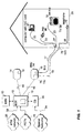
- FIG. 1 a broadband access system for delivery of video, data (for a computer network interface) and telephony services is shown.
- a broadband access system for delivery of video, data (for a computer network interface) and telephony services is shown.
- techniques disclosed herein may be used in connection with other services/technologies, the preferred embodiment will be discussed in connection with the delivery and distribution of digital video signals. Components used for these other services are not needed to understand the subject invention, and are only described to the extent their presence may be pertinent to the understanding of the subject invention.
- the digital broadband access system typically includes a broadband digital terminal (BDT) 12 connected to a broadband network unit (BNU) 14.
- BDT broadband digital terminal
- BNU broadband network unit
- the BDT 12 can be equipped with an element management system (EMS) 13 that provisions services and equipment, and for handling certain video signal controls on the digital broadband access system.
- EMS 13 is usually software based and can be implemented on either a personal computer or a workstation.
- a personal computer based EMS can support one BDT 12 and its associated broad access network equipment.
- a workstation can support multiple BDT's 12 and their respective access network equipment.
- video programming is primarily input to the broadband access system via an Asynchronous Transfer Mode (ATM) network 26 connected to the BDT 12.
- ATM Asynchronous Transfer Mode
- the BDT 12, through communication with a Channel Bank (CB) 30 can also receive special services signals from private networks or non-switched public networks 32 for transmission through the broadband access system via a connection with a special networks-CB interface 34.
- the CB 30 is connected to the BDT 12 allowing customers to order programming from the special private or public networks.
- the interface to the ATM network-BDT interface 39 can be realized using an OC-3 or OC-12 optical interfaces carrying ATM cells.
- BDT 12 has two OC-12c broadcast ports, which can only receive signals carrying ATM cells, and one OC-12c interactive port which can receive and transmit signals.
- the BDT 12 can also be connected to the Public Switched Telecommunications Network (PSTN) 70.
- PSTN Public Switched Telecommunications Network
- the physical interface to the PSTN is twisted wire pairs supporting the transmission of DS-1 signals, or optical fiber supporting the transmission of OC-3 optical signals.
- the BDT 12 is typically located in a facility owned by the video/data service provider, for example, the central office of a Regional Bell Operating Company.
- the BNU 14 is located in the serving area usually on a telephone pole (i.e., at the "curb") proximate the houses 29 of the subscribers.
- the preferred connection between the BDT 12 and BNU 14 is made with an optical fiber cable 16 and is sometimes called a fiber-to-the-curb (FTTC) architecture.
- FTTC fiber-to-the-curb
- the FTTC architecture is an outgrowth of Digital Loop Carrier (DLC) technology which was developed in the early 1970's to provide telephone service to areas remotely located from a telephone company's central office. Capable of utilizing digital switching, the FTTC architecture has the advantage of being compatible with both isochronous telephone network and packet/cell based network and is thus well suited for providing Internet access and Switched Digital Video (SDV).
- DLC Digital Loop Carrier
- the optical fiber 16 is a single-mode fiber and a dual wavelength transmission scheme is used to transmit signals between BDT 12 and BNU 14. Digital signals pass back and forth between BDT 12 and BNU 14 at a rate of 155Mb/s utilizing Synchronous Digital Hierarchy (SDH).
- SDH Synchronous Digital Hierarchy
- the BDT 12 can be connected to scores of BNU's, but the actual number depends on the services offered and the number of subscribers being served. In a preferred embodiment, up to sixty-four BNU's are served by each BDT 12.
- Each BNU 14 has multiple drops for serving a plurality of subscribers. Typically, each BNU 14 can serve sixteen subscribers' houses 29.
- the drops for delivering video services are preferably coaxial cable 17. (Although optical fiber may be used to deliver the video signals from the BIU 15 to each subscriber's house 29, the preferred connection is made with coaxial cable 17 for economic reasons.)
- a broadband interface unit (BIU) 15 is needed to convert the digital signals delivered to the BNU 14 by the optical fiber cable 16 into analog signals.
- the broadband interface unit 15 is located within BNU 14 and generates broadband signals which contain video, data and voice information.
- the BIU 15 ultimately communicates with various devices inside the subscriber's house 29. These may include Premises Interface Devices 96, Network Interface Cards 91 and television set-top units 19.
- BIU 15 modulates data onto an RF carrier and transmits the data over the coaxial drop cable 17.
- the BIU 15 is connected to the set-top unit 19, either directly or through a splitter 27 as shown in FIG. 1 .
- the splitter 27 is used when the broadband access system is utilized to deliver other services (e.g., high speed Internet access and/or telephony), in addition to video, to the subscriber or to provide signals to multiple set-top units.
- the connection between splitter 27 and the various devices within the subscriber's home 29 is preferably made with an in-home coaxial wiring 33.
- an interface subsystem including an active device sometimes referred to as a "residential gateway" (in contrast to the passive splitter 27), may be used to control and direct the various services within the subscriber's home 29, and to convert signals received from BIU 15 to the appropriate format required by each device.
- In-home coaxial wiring 33 connects set-top unit 19 with splitter 27.
- the set-top unit 19 is connected to a television 39 in the normal manner. If the signals generated by BIU 15 are still not compatible with a specific television unit 39, the set-top 19 may include additional circuitry that converts the video signals from the BIU to signals compatible with any television 39 present in the home 29.
- the BNU 14 may contain a Telephone Interface Unit (TIU) 75 which generates an analog Plain Old Telephony (POT) signal.
- a twisted wire pair drop 18 is shown in FIG. 1 for delivering traditional narrowband Plain Old Telephony (POT) service to all subscribers.
- the subscriber's telephone 79 is preferably connected to the TIU 75 through a Network Interface Device 78. If the deployment scenario is such that construction considerations prohibit the installation of coaxial cable drops 17, the relatively recent developments in transmission line technologies (e.g., High Speed Digital Subscriber Line, Asymmetric Digital Subscriber Line, and Very High Rate Digital Subscriber Line, sometimes each is referred to as xDSL technologies) allow high speed services to be delivered over the twisted wire pair 18.
- xDSL technologies allow high speed services to be delivered over the twisted wire pair 18.
- a cable box i.e., a type of set-top unit used by cable TV service providers.
- the subscriber accesses the cable box/set-top unit.
- the cable box actually performs the channel changing and decryption of the incoming video signals.
- the actual changing of the channel is performed by circuitry 10 within the BDT 12 or BNU 14, and only one or two video channels at a time are typically delivered to the subscriber's set top unit 19.
- the video service provider controls the delivery of the video signal at a point upstream from the subscriber, it reduces the possibility that the subscriber can tamper with the system and reduces theft of services. This, in turn, eliminates the need for encryption of the video signal and further reduces the complexity of set-top units.
- the subscriber By locating the channel changing circuitry at a distance away from the subscriber's television, the subscriber experiences a delay in time between each channel change on his television. As the following example will show, in which the subscriber changes the channel viewed on television set 39 to channel X, an unacceptable delay may be caused.
- FIG. 2A illustrates the initial transmission of the control signals between the set-top unit 19 and the BDT 12 when a subscriber makes a request for a change of channel to channel X.
- the set-top unit 19 sends a request for channel change to channel X to the BDT 12 over the broadband access system as illustrated by the control plane in FIG. 2A .
- the BDT 12 After receiving the request from the set-top unit 19, the BDT 12 must then determine if it is a proper request and, if proper, acknowledge the set top unit 19 with a confirmation signal sent over the access system. (See FIG. 2A again.) When the BDT synchronizes with channel X, it must then direct the corresponding video data downstream to the appropriate set top unit 19 as illustrated by the user/service plane of FIG. 2B .
- FIG. 1 the illustrations of Figs. 2A and 2B of the signal transmissions over the broadband access system show the relative travel of, and number of, signals being transmitted between a single set-top unit and a BDT 12, one must refer back to FIG. 1 to fully appreciate the time delay incurred in a "typical" channel change request.
- the subscriber must communicate his request to change to new channel X to the set-top unit 19; this is usually done through the use of a common infrared remote control.
- the request for channel X must travel upstream from the set-top unit 19 to the BIU 15.
- the control signal must be received by the BIU and passed to the BNU 14.
- the BNU 14 bundles all of the received control signals from the multiple set-top units it serves and transmits them to the BDT.
- the BDT 12, under control of the EMS 13, must determine if the channel change request is valid and if that particular subscriber has paid for the requested service.
- the BDT will acknowledge receipt of the change of channel request. This is done through the BDT 12, under control of the EMS 13, by generating a confirmation signal to change to channel X back down the fiber optic cable to the BNU 14. The BNU 14 then directs the confirmation signal to the appropriate set-top unit. Meanwhile, the BDT 12 must then synchronize with channel X as it is received from the ATM network. Channel X is decompressed, and then multiplexed with the other video signals corresponding to the channels requested by the various other subscribers. Once BNU 14 receives the multiplexed signal, it is demultiplexed and the appropriate signal is directed to the set-top units of the appropriate requesting subscribers.
- Asynchronous Transfer Mode (ATM) network was designed with the flexibility to meet the needs of many types of user data with a single format.
- the data transmitted over an ATM system can include digital video, digitized voice, computer data and transaction information (such as between an automated banking machine and a central computer) over both local and wide area networks.
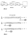
- the ATM format does not specify data rates or a physical channel, but calls for relatively short bit segments. Specifically, the ATM format calls for a fifty-three byte cell format, as shown in FIG. 3 , which allocates five bytes for overhead and forty-eight bytes for actual data. The utilization of a short bit segment is important when the mixture of data signals include computer data.
- the cell format for systems that handle computer data is relatively long. This would be unacceptable for "mixed" systems that transmit "real-time" signals such as video and voice.
- the short cell format of the ATM systems ensures that traffic from real-time sources do not have to wait an extraordinary period of time before they can be sent between the computer data cells.
- the five byte header of an ATM cell contains all of the information needed to relay the cell from one node to the next node, over a pre-established route.
- the video data is contained in the forty-eight byte information field.
- a compression scheme is preferably utilized to pack more video data into each information field.
- Virtually all of the compression schemes require a starting or synchronization frame usually referred to as the Group of Picture (GOP) start point.
- GOP Group of Picture
- the GOP start point is found proximate the beginning of the information field as illustrated in FIG. 3 .
- the BDT 12 After receiving the request from a subscriber to change to a new channel, the BDT 12 must then wait for the Group of Picture (GOP) start point of the requested channel.
- GOP Group of Picture
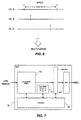
- the time between GOP start points is significant. As illustrated in FIG. 4 , the time delay between GOP B1 and GOP B2 may be 1 ⁇ 2 second or more depending on the compression scheme and other factors.
- the BDT 12 After the BDT 12 synchronizes with the appropriate GOP start point, it can then decompress the requested signal and direct it to the subscriber(s) who have requested it.
- the signal corresponding to the requested channels is then multiplexed with the signals corresponding to the requested channel of all other subscribers handled by that BDT 12.
- the multiplexed signal is then transmitted downstream to BNU 14, where the signal is demuxed and directed to the appropriate set-top units 19.
- the compressed format used to encode the video data is the Moving Pictures Experts Group 2 format, known as MPEG-2.
- MPEG-2 Moving Pictures Experts Group 2 format
- the data is transmitted as one of three basic frames.
- the GOP start point is coded in the "I" or intracoded frames.
- I frames In addition to the I frames, there are predicted frames and bidirectional frames (P and B frames, respectively).
- P and B frames normally contain the video and audio content.
- Each synchronization frame is separated from the next synchronization frame by a pre-determined number of other frames. This predetermined number can be set to accommodate a specific requirement but in one preferred embodiment is fifteen frames.
- the MPEG-2 cells comprise video data in P or B frames between synchronization or I frames.
- the MPEG-2 cells of a particular video channel may be transmitted in a individual ATM cell or the MPEG-2 cells of multiple video channels may be multiplexed onto an ATM cell or cells.
- the time between I frames under the embodiment utilizing MPEG-2 is approximately 1 ⁇ 2 second. Therefore, depending on when the BDT receives a channel change request, there can be up to a 1 ⁇ 2 second delay just for the BDT to synchronize with the I frame. Additional time must be allowed for the request to reach the BDT from the set-top, acknowledgment of the request, and eventually for transmission of the requested video signal back to the subscriber's set-top that made the request.
- the BDT 12 is connected to a video source (ATM network 26 or special network 34) that provide a plurality of compressed video signals.
- the compressed video signals are transmitted using the MPEG-2 format which utilizes a synchronization frame called the intracoded or "I" frame.
- I a synchronization frame
- digital video delivery systems in contrast with analog systems, require a synchronization or start frame.
- the I frame is transmitted about every 1 ⁇ 2 second in MPEG-2. Accordingly, it may take over a second between the time a subscriber bequests a certain channel and can then actually view the requested channel on the television 39. The largest portion of the one second delay is caused by the wait for the video processor in the BDT to synchronize with the next available I frame.
- the subject rapid channel changer 10 is designed to minimize any delay between a subscriber's request to change a television channel and the actual delivery of the signal corresponding to the desired channel.
- the subject invention 10 includes a first-in-first-out (FIFO) buffer 50 for storing the compressed video data of each video channel, and a processor 55 for indexing the synchronization frames.
- FIFO first-in-first-out
- the processor 55 detects the GOP start frame (or I frame in the preferred embodiment) for each channel received and establish a pointer for each GOP start frame. The processor 55 then records the I frame pointer location for each channel in a second buffer 57.
- FIFO buffer 50 As new video information is received into FIFO buffer 50, the previous information is counted out.
- the FIFO buffer 50 must hold at least the minimum number of frames in the compression scheme so that at least one GOP frame for each video channel is stored at all times in the buffer. Therefore as one I frame for channel X leaves the FIFO buffer a new I frame must enter (see FIG. 5 ).
- the processor detects the new I frame and records the new pointer location for future reference.
- the FIFO buffer 50 of the rapid channel changer 10 stores, at a minimum, fifteen frames (i.e., one I frame and fourteen P or B frames) for each channel that is received by the BDT.
- multiple buffer memory units may be used, e.g., one for each video channel.
- the processor detects each I frame as it enters the buffer and keeps track of its position as it moves through the buffer (i.e., indexing the I frame).
- the requested signal can instantly be transmitted downstream to the subscriber since the processor 55 is always "pointing" to an I frame for each respective channel. Accordingly, the largest portion of the channel changing delay - up to a 1 ⁇ 2 second that the processor had to wait for the next synchronization frame - is eliminated.
- the processor can immediately look up the location of the I frame from the pointer location buffer 57 and immediately accesses the appropriate video data.
- the BDT then sends a stream of data from the FIFO buffer 50 to a multiplexer 44 to generate a multiplexed signal for transmission to BNU 14.
- a FIFO buffer 50 for each compressed video signal is desirable.
- a subscriber may have forty channels from which to choose; therefore, forty channels may be sent from the ATM network 26 to the BDT 12. Accordingly, forty FIFO buffers 50 will be used for this example of the rapid channel changer 10.
- the FIFO buffer may be desirable for the FIFO buffer to store two or more synchronization frames per video signal (i.e., each buffer stores at least thirty frames in the aforementioned MPEG-2 embodiment utilizing fifteen frames in each cell). In this manner, the BDT 12 can direct different channel requests to thousands of subscribers regardless of the actual location of the synch frame on any broadcast video signal.
- a signal is sent to the set-top unit 19 and travels upstream through the BNU 14 to the BDT 12.
- the I frame of buffer 50 is accessed by microprocessor 55.
- the processor 55 has stored the information corresponding to intracoded frame I x .
- the processor 55 stores the position of the next intracoded frame I x+1 .
- the processor 55 keeps continuous track of the I frame. Accordingly, the processor 55 can immediately synchronize with the video signal stored in the FIFO buffer 50. Since the processor 55 can immediately synchronize with the video signal, it can substantially simultaneously direct the desired video data from FIFO buffer 50 to the multiplexer 44 for eventual transmission downstream to the subscriber.
- the BDT may also determine whether the requested channel is already being transmitted to the requesting BNU. If so, there may be no need to transmit an additional signal with the same video channel information. The BNU will replicate the signal and send it to the second requesting subscriber.
- the video channel buffers and processor may be located in BNU 14, if desired.
- the invention is intended to be protected broadly within the scope of the appended claims.
Description
- The present invention relates generally to an apparatus for the distribution and delivery of video in a digital system and, in particular, to a method and apparatus that rapidly changes the channel in such a system.
- In a typical analog cable system all of the channels or services ordered by the subscriber are delivered to each subscriber's home. In order to ensure that each subscriber receives only the channels for which he has paid, the cable television providers encrypt or "scramble" the premium channels (HBO, CINEMAX, DISNEY, etc.). The cable television providers also may scramble many of the "basic" channels (local stations, ESPN, MTV, VH1, TNT, DISCOVERY, etc.). Therefore, even though virtually all television sets sold today are cable-ready, most subscribers still need a set-top unit (sometimes referred to as a cable box in the cable television environment) to descramble the signals. The set-top units are located proximate a television and are also used to change the channel that is viewed on the television.
- Subscribers, especially residential subscribers, are demanding that large amounts of information and more choices of services be brought into their homes. Switched video for viewing on a subscriber's television and high-speed Internet access are two services highly desired by subscribers. In order to meet the demand, and to accommodate the recently approved high-definition television standards, the new services will likely have to be capable of handling digital signals.
- In addition to the emerging technologies, entry of the Regional Bell Operating Companies (RBOCs) have made digital delivery systems economically feasible. A typical digital video delivery system includes a means for receiving the video signals from various broadcast sources, a means for delivering the signals to a plurality of subscribers, and a means of transmitting the signals between the receiving means and delivering means. The means for receiving the video signals may include a broadband digital terminal (BDT) located in a central office. The delivering means may be a broadband network unit (BNU) located preferably on a telephone pole or other convenient location proximate a number of subscribers. Cable or optical fiber connects the BDT to the BNU. A second cable (or a twisted wire pair) connects the set-top units (and, if required, the various other units in the subscriber's home) with the BNU.
- In a typical digital video system, all of the video services offered by the video service company are again delivered to the set-top unit. When selecting a new channel, the set-top unit performs the actual switching and also descrambles the digital signals.
- Even though the premium channels are scrambled, delivering all of the video signals into a subscriber's home makes the video services susceptible to theft. Accordingly, more complex - and expensive - steps must be taken to further secure the transmission and delivery of the video services.
- A solution to the theft problem is to perform the channel switching "upstream" from the subscriber at a facility controlled by the video provider (in a digital system at the BDT, for example), and only delivering one channel at a time to the subscriber's set-top unit. Another advantage of moving the switching upstream is that the bandwidth requirements of the overall video delivery system are greatly reduced. However, a drawback of this system is that the subscriber experiences a time delay between the period of time it takes for the subscriber to select a channel and for the newly selected channel to be viewed on the television.
- The reason for this time delay is that the subscriber's request must first travel upstream to the BDT; next, the BDT must acknowledge the request, then synchronize and "lock on" to the desired video service; finally, the BDT must transmit the desired video service back downstream to the subscriber. The overall delay between each channel change can take over a second.
- A significant portion of the delay is caused by the time it takes for the video signal to synchronize. This portion accounts for about half of the overall delay (i.e., about a half second). Many subscribers find the delay in such video delivery systems annoying since they are accustomed to seeing the broadcast signal immediately after selecting a new channel. Most subscribers find that a one second delay is unacceptable, which would make such a system competitively unattractive.
- There is provided a method of switching to a video channel as set out in
claim 1, and a channel changer as set out inclaim 5. - The present invention relates to a method and apparatus for rapidly changing the channel in a digital video delivery system.
- The rapid channel changer will be preferably located in the central office with the broadband digital terminal (BDT) and indexes the "start" or synchronization frame of each video channel received at the BDT.
- Each digital video signal includes a synchronization frame. The subject channel changer captures the multiple compressed video signals and stores each signal in a cache buffer. A processor is used to index or "point to" the respective synchronization frames for each buffered signal.
- When a subscriber requests a specific channel or video service, the processor can immediately access the requested video signal at a synchronization frame and direct the video stream to the subscriber since the processor already has the position of the synchronization frame of each video signal.
- Accordingly, the period of time that the subscriber previously had to wait for the synchronization frame is eliminated.
- These and other features and objects of the invention will be more fully understood from the following detailed description of the preferred embodiments which should be read in light of the accompanying drawings.
- The accompanying drawings, which are incorporated in and form a part of the specification, illustrate the embodiments of the present invention and, together with the description serve to explain the principles of the invention.
- In the drawings:
-
FIG. 1 illustrates generally a broadband access system, capable of delivering video, data and voice information; -
FIG. 2A illustrates the signaling control plane; -
FIG. 2B illustrates the user/service control plane; -
FIG. 3 shows the two major fields of an ATM cell; -
FIG. 4 illustrates a stream of ATM cells and the sequencing of a plurality of video channels and the relative location of their respective GOP frames; -
FIG. 5 illustrates the relative positions of a synchronization or I frame as it moves through a FIFO buffer for a single channel X; -
FIG. 6 illustrates a series of MPEG-2 cells for a plurality of video channels; and -
FIG. 7 is a schematic of a channel changer in accordance with the present invention. - In describing a preferred embodiment of the invention illustrated in the drawings, specific terminology will be used for the sake of clarity. However, the invention is not intended to be limited to the specific terms so selected, and it is to be understood that each specific term includes all technical equivalents that operate in a similar manner to accomplish a similar purpose.
- With reference to the drawings, in general, and
FIGS. 1 through 7 in particular, the apparatus of the present invention is disclosed. - As shown in
FIG. 1 , a broadband access system for delivery of video, data (for a computer network interface) and telephony services is shown. Although techniques disclosed herein may be used in connection with other services/technologies, the preferred embodiment will be discussed in connection with the delivery and distribution of digital video signals. Components used for these other services are not needed to understand the subject invention, and are only described to the extent their presence may be pertinent to the understanding of the subject invention. - This invention relates to a rapid channel changer, generally indicated at 10, for use in a digital broadband access system. The digital broadband access system typically includes a broadband digital terminal (BDT) 12 connected to a broadband network unit (BNU) 14.
- The BDT 12 can be equipped with an element management system (EMS) 13 that provisions services and equipment, and for handling certain video signal controls on the digital broadband access system. The EMS 13 is usually software based and can be implemented on either a personal computer or a workstation. A personal computer based EMS can support one
BDT 12 and its associated broad access network equipment. A workstation can support multiple BDT's 12 and their respective access network equipment. - In a preferred embodiment, video programming is primarily input to the broadband access system via an Asynchronous Transfer Mode (ATM)
network 26 connected to theBDT 12. TheBDT 12, through communication with a Channel Bank (CB) 30 can also receive special services signals from private networks or non-switched public networks 32 for transmission through the broadband access system via a connection with a special networks-CB interface 34. TheCB 30 is connected to theBDT 12 allowing customers to order programming from the special private or public networks. - The interface to the ATM network-
BDT interface 39 can be realized using an OC-3 or OC-12 optical interfaces carrying ATM cells. In a preferred embodiment,BDT 12 has two OC-12c broadcast ports, which can only receive signals carrying ATM cells, and one OC-12c interactive port which can receive and transmit signals. - For the purpose of illustration, the
BDT 12 can also be connected to the Public Switched Telecommunications Network (PSTN) 70. The physical interface to the PSTN is twisted wire pairs supporting the transmission of DS-1 signals, or optical fiber supporting the transmission of OC-3 optical signals. - The
BDT 12 is typically located in a facility owned by the video/data service provider, for example, the central office of a Regional Bell Operating Company. TheBNU 14 is located in the serving area usually on a telephone pole (i.e., at the "curb") proximate thehouses 29 of the subscribers. The preferred connection between theBDT 12 andBNU 14 is made with anoptical fiber cable 16 and is sometimes called a fiber-to-the-curb (FTTC) architecture. - The FTTC architecture is an outgrowth of Digital Loop Carrier (DLC) technology which was developed in the early 1970's to provide telephone service to areas remotely located from a telephone company's central office. Capable of utilizing digital switching, the FTTC architecture has the advantage of being compatible with both isochronous telephone network and packet/cell based network and is thus well suited for providing Internet access and Switched Digital Video (SDV).
- In the preferred embodiment, the
optical fiber 16 is a single-mode fiber and a dual wavelength transmission scheme is used to transmit signals betweenBDT 12 andBNU 14. Digital signals pass back and forth betweenBDT 12 andBNU 14 at a rate of 155Mb/s utilizing Synchronous Digital Hierarchy (SDH). - The
BDT 12 can be connected to scores of BNU's, but the actual number depends on the services offered and the number of subscribers being served. In a preferred embodiment, up to sixty-four BNU's are served by eachBDT 12. - Each
BNU 14 has multiple drops for serving a plurality of subscribers. Typically, eachBNU 14 can serve sixteen subscribers'houses 29. The drops for delivering video services are preferablycoaxial cable 17. (Although optical fiber may be used to deliver the video signals from theBIU 15 to each subscriber'shouse 29, the preferred connection is made withcoaxial cable 17 for economic reasons.) - Since many of the devices presently in use by the subscriber accept only analog signals, a broadband interface unit (BIU) 15 is needed to convert the digital signals delivered to the
BNU 14 by theoptical fiber cable 16 into analog signals. Thebroadband interface unit 15 is located withinBNU 14 and generates broadband signals which contain video, data and voice information. TheBIU 15 ultimately communicates with various devices inside the subscriber'shouse 29. These may includePremises Interface Devices 96,Network Interface Cards 91 and television set-top units 19.BIU 15 modulates data onto an RF carrier and transmits the data over thecoaxial drop cable 17. - The
BIU 15 is connected to the set-top unit 19, either directly or through asplitter 27 as shown inFIG. 1 . Thesplitter 27 is used when the broadband access system is utilized to deliver other services (e.g., high speed Internet access and/or telephony), in addition to video, to the subscriber or to provide signals to multiple set-top units. The connection betweensplitter 27 and the various devices within the subscriber'shome 29 is preferably made with an in-home coaxial wiring 33. In alternate embodiments, an interface subsystem, including an active device sometimes referred to as a "residential gateway" (in contrast to the passive splitter 27), may be used to control and direct the various services within the subscriber'shome 29, and to convert signals received fromBIU 15 to the appropriate format required by each device. - In-
home coaxial wiring 33 connects set-top unit 19 withsplitter 27. The set-top unit 19 is connected to atelevision 39 in the normal manner. If the signals generated byBIU 15 are still not compatible with aspecific television unit 39, the set-top 19 may include additional circuitry that converts the video signals from the BIU to signals compatible with anytelevision 39 present in thehome 29. - The
BNU 14 may contain a Telephone Interface Unit (TIU) 75 which generates an analog Plain Old Telephony (POT) signal. A twistedwire pair drop 18 is shown inFIG. 1 for delivering traditional narrowband Plain Old Telephony (POT) service to all subscribers. The subscriber'stelephone 79 is preferably connected to theTIU 75 through aNetwork Interface Device 78. If the deployment scenario is such that construction considerations prohibit the installation of coaxial cable drops 17, the relatively recent developments in transmission line technologies (e.g., High Speed Digital Subscriber Line, Asymmetric Digital Subscriber Line, and Very High Rate Digital Subscriber Line, sometimes each is referred to as xDSL technologies) allow high speed services to be delivered over thetwisted wire pair 18. - In most video access systems (especially in analog systems that are commonly used today), all of the channels and services requested by the subscriber are simultaneously delivered to a cable box (i.e., a type of set-top unit used by cable TV service providers). When the subscriber wants to change the channel on the
television 39, the subscriber accesses the cable box/set-top unit. The cable box actually performs the channel changing and decryption of the incoming video signals. - Most video access systems (including the newer digital systems that have more recently been developed and deployed) still simultaneously deliver all or most of the channels to a set-top unit in a subscriber's home. Generally speaking, these newer set top units require more complex circuitry than the older cable boxes. Part of the reason is that newer systems are designed to handle more channels and to perform more complex decryption of a signal in order to reduce theft.
- In the present invention, the actual changing of the channel is performed by
circuitry 10 within theBDT 12 orBNU 14, and only one or two video channels at a time are typically delivered to the subscriber's settop unit 19. This reduces the complexity and the cost of the subscriber's set-top unit 19. More importantly, since the video service provider controls the delivery of the video signal at a point upstream from the subscriber, it reduces the possibility that the subscriber can tamper with the system and reduces theft of services. This, in turn, eliminates the need for encryption of the video signal and further reduces the complexity of set-top units. - By locating the channel changing circuitry at a distance away from the subscriber's television, the subscriber experiences a delay in time between each channel change on his television. As the following example will show, in which the subscriber changes the channel viewed on
television set 39 to channel X, an unacceptable delay may be caused. - Reference is now made to the signaling control plane of
FIG. 2A , which illustrates the initial transmission of the control signals between the set-top unit 19 and theBDT 12 when a subscriber makes a request for a change of channel to channel X. The set-top unit 19 sends a request for channel change to channel X to theBDT 12 over the broadband access system as illustrated by the control plane inFIG. 2A . After receiving the request from the set-top unit 19, theBDT 12 must then determine if it is a proper request and, if proper, acknowledge the settop unit 19 with a confirmation signal sent over the access system. (SeeFIG. 2A again.) When the BDT synchronizes with channel X, it must then direct the corresponding video data downstream to the appropriateset top unit 19 as illustrated by the user/service plane ofFIG. 2B . - Although the illustrations of
Figs. 2A and 2B of the signal transmissions over the broadband access system show the relative travel of, and number of, signals being transmitted between a single set-top unit and aBDT 12, one must refer back toFIG. 1 to fully appreciate the time delay incurred in a "typical" channel change request. First, the subscriber must communicate his request to change to new channel X to the set-top unit 19; this is usually done through the use of a common infrared remote control. The request for channel X must travel upstream from the set-top unit 19 to theBIU 15. The control signal must be received by the BIU and passed to theBNU 14. TheBNU 14 bundles all of the received control signals from the multiple set-top units it serves and transmits them to the BDT. TheBDT 12, under control of theEMS 13, must determine if the channel change request is valid and if that particular subscriber has paid for the requested service. - If these first two criteria are met, the BDT will acknowledge receipt of the change of channel request. This is done through the
BDT 12, under control of theEMS 13, by generating a confirmation signal to change to channel X back down the fiber optic cable to theBNU 14. TheBNU 14 then directs the confirmation signal to the appropriate set-top unit. Meanwhile, theBDT 12 must then synchronize with channel X as it is received from the ATM network. Channel X is decompressed, and then multiplexed with the other video signals corresponding to the channels requested by the various other subscribers. OnceBNU 14 receives the multiplexed signal, it is demultiplexed and the appropriate signal is directed to the set-top units of the appropriate requesting subscribers. - Although the change of channel appears to be straightforward, not insignificant delays force the subscriber to wait for the requested channel before it is actually viewable on the television set. A portion of the delay is caused by the fact that the BDT is located miles away from each subscriber. Since all channels are not delivered to the subscriber's set-top unit simultaneously, it takes time for the control signals and the information to traverse the distance between the set-top and the
BDT 12. - Another portion of the delay is caused by the synchronization method utilized by the
BDT 12 to synchronize with the signals received from theATM network 26. The Asynchronous Transfer Mode (ATM) network was designed with the flexibility to meet the needs of many types of user data with a single format. The data transmitted over an ATM system can include digital video, digitized voice, computer data and transaction information (such as between an automated banking machine and a central computer) over both local and wide area networks. - The ATM format does not specify data rates or a physical channel, but calls for relatively short bit segments. Specifically, the ATM format calls for a fifty-three byte cell format, as shown in
FIG. 3 , which allocates five bytes for overhead and forty-eight bytes for actual data. The utilization of a short bit segment is important when the mixture of data signals include computer data. The cell format for systems that handle computer data is relatively long. This would be unacceptable for "mixed" systems that transmit "real-time" signals such as video and voice. The short cell format of the ATM systems ensures that traffic from real-time sources do not have to wait an extraordinary period of time before they can be sent between the computer data cells. - The five byte header of an ATM cell contains all of the information needed to relay the cell from one node to the next node, over a pre-established route. The video data is contained in the forty-eight byte information field.
- A compression scheme is preferably utilized to pack more video data into each information field. Virtually all of the compression schemes require a starting or synchronization frame usually referred to as the Group of Picture (GOP) start point. In most compression schemes the GOP start point is found proximate the beginning of the information field as illustrated in
FIG. 3 . - After receiving the request from a subscriber to change to a new channel, the
BDT 12 must then wait for the Group of Picture (GOP) start point of the requested channel. Even if the ATM system is dedicated strictly to video, the time between GOP start points is significant. As illustrated inFIG. 4 , the time delay between GOPB1 and GOPB2 may be ½ second or more depending on the compression scheme and other factors. - After the
BDT 12 synchronizes with the appropriate GOP start point, it can then decompress the requested signal and direct it to the subscriber(s) who have requested it. The signal corresponding to the requested channels is then multiplexed with the signals corresponding to the requested channel of all other subscribers handled by thatBDT 12. The multiplexed signal is then transmitted downstream toBNU 14, where the signal is demuxed and directed to the appropriate set-top units 19. - In the preferred embodiment, the compressed format used to encode the video data is the Moving Pictures Experts Group 2 format, known as MPEG-2. As shown in
FIG. 5 , the data is transmitted as one of three basic frames. The GOP start point is coded in the "I" or intracoded frames. In addition to the I frames, there are predicted frames and bidirectional frames (P and B frames, respectively). The P and B frames normally contain the video and audio content. Each synchronization frame is separated from the next synchronization frame by a pre-determined number of other frames. This predetermined number can be set to accommodate a specific requirement but in one preferred embodiment is fifteen frames. - Referring to
FIG. 6 , the MPEG-2 cells comprise video data in P or B frames between synchronization or I frames. The MPEG-2 cells of a particular video channel may be transmitted in a individual ATM cell or the MPEG-2 cells of multiple video channels may be multiplexed onto an ATM cell or cells. The time between I frames under the embodiment utilizing MPEG-2 is approximately ½ second. Therefore, depending on when the BDT receives a channel change request, there can be up to a ½ second delay just for the BDT to synchronize with the I frame. Additional time must be allowed for the request to reach the BDT from the set-top, acknowledgment of the request, and eventually for transmission of the requested video signal back to the subscriber's set-top that made the request. Even though the physical distance at which the BDT is located from the set-top has some effect on the time delay a subscriber experiences between channel changes, the signals are traveling at the speed of light and cannot be made to go any faster. Constructing more BDT's closer to each subscriber is usually not economically feasible or practical. Therefore, a quicker and/or more efficient method or device to handle the incoming ATM signal is needed to reduce the overall amount of time the subscriber must wait between channel changes. - Referring now to
FIG. 7 , theBDT 12 is connected to a video source (ATM network 26 or special network 34) that provide a plurality of compressed video signals. In a preferred embodiment, the compressed video signals are transmitted using the MPEG-2 format which utilizes a synchronization frame called the intracoded or "I" frame. (As explained previously, digital video delivery systems, in contrast with analog systems, require a synchronization or start frame.) - The I frame is transmitted about every ½ second in MPEG-2. Accordingly, it may take over a second between the time a subscriber bequests a certain channel and can then actually view the requested channel on the
television 39. The largest portion of the one second delay is caused by the wait for the video processor in the BDT to synchronize with the next available I frame. The subjectrapid channel changer 10 is designed to minimize any delay between a subscriber's request to change a television channel and the actual delivery of the signal corresponding to the desired channel. - Referring again to
FIG. 7 , thesubject invention 10 includes a first-in-first-out (FIFO)buffer 50 for storing the compressed video data of each video channel, and aprocessor 55 for indexing the synchronization frames. (Note that if theBDT 12 already utilizes buffers to store the video data for each channel it is supposed to receive, and a processor, the subject invention can be implemented in existing hardware, which minimizes additional costs.) Theprocessor 55 detects the GOP start frame (or I frame in the preferred embodiment) for each channel received and establish a pointer for each GOP start frame. Theprocessor 55 then records the I frame pointer location for each channel in asecond buffer 57. - Referring again to
FIG. 5 , as new video information is received intoFIFO buffer 50, the previous information is counted out. TheFIFO buffer 50 must hold at least the minimum number of frames in the compression scheme so that at least one GOP frame for each video channel is stored at all times in the buffer. Therefore as one I frame for channel X leaves the FIFO buffer a new I frame must enter (seeFIG. 5 ). The processor then detects the new I frame and records the new pointer location for future reference. - In the preferred embodiment, the
FIFO buffer 50 of therapid channel changer 10 stores, at a minimum, fifteen frames (i.e., one I frame and fourteen P or B frames) for each channel that is received by the BDT. Alternatively, multiple buffer memory units may be used, e.g., one for each video channel. The processor detects each I frame as it enters the buffer and keeps track of its position as it moves through the buffer (i.e., indexing the I frame). When a subscriber's channel change request is received by the BDT, the requested signal can instantly be transmitted downstream to the subscriber since theprocessor 55 is always "pointing" to an I frame for each respective channel. Accordingly, the largest portion of the channel changing delay - up to a ½ second that the processor had to wait for the next synchronization frame - is eliminated. - Referring again to
FIG. 7 , when a change of channel request reachesBDT 12, the processor can immediately look up the location of the I frame from thepointer location buffer 57 and immediately accesses the appropriate video data. The BDT then sends a stream of data from theFIFO buffer 50 to amultiplexer 44 to generate a multiplexed signal for transmission toBNU 14. - A
FIFO buffer 50 for each compressed video signal is desirable. In a typical example, a subscriber may have forty channels from which to choose; therefore, forty channels may be sent from theATM network 26 to theBDT 12. Accordingly, fortyFIFO buffers 50 will be used for this example of therapid channel changer 10. - There only needs to be one
pointer buffer 57 since it only stores the pointer locations of the forty GOP frames. A single processor can easily keep track of forty buffer locations and, in fact, the processor can index many more I frames. Accordingly, it may be desirable for the FIFO buffer to store two or more synchronization frames per video signal (i.e., each buffer stores at least thirty frames in the aforementioned MPEG-2 embodiment utilizing fifteen frames in each cell). In this manner, theBDT 12 can direct different channel requests to thousands of subscribers regardless of the actual location of the synch frame on any broadcast video signal. - When a subscriber decides to change the channel on his TV, a signal is sent to the set-
top unit 19 and travels upstream through theBNU 14 to theBDT 12. If, for example, the subscriber wishes to change TV channels to the one corresponding with video channel X, the I frame ofbuffer 50 is accessed bymicroprocessor 55. At time t1, as shown inFIG. 5 , theprocessor 55 has stored the information corresponding to intracoded frame Ix. At a later time t2, theprocessor 55 stores the position of the next intracoded frame Ix+1. As Ix+1 moves throughbuffer 50, theprocessor 55 keeps continuous track of the I frame. Accordingly, theprocessor 55 can immediately synchronize with the video signal stored in theFIFO buffer 50. Since theprocessor 55 can immediately synchronize with the video signal, it can substantially simultaneously direct the desired video data fromFIFO buffer 50 to themultiplexer 44 for eventual transmission downstream to the subscriber. - In a preferred embodiment, the BDT may also determine whether the requested channel is already being transmitted to the requesting BNU. If so, there may be no need to transmit an additional signal with the same video channel information. The BNU will replicate the signal and send it to the second requesting subscriber.
- Although this invention has been illustrated by reference to specific embodiments, it will be apparent to those skilled in the art that various changes and modifications may be made which clearly fall within the scope of the invention. For example, in an alternative embodiment, the video channel buffers and processor may be located in
BNU 14, if desired. The invention is intended to be protected broadly within the scope of the appended claims.
Claims (12)
- A method of switching to a video channel requested by a subscriber in a switched digital video system, said method comprising the steps of:inputting compressed video data corresponding to a plurality of video channels into a first memory means comprising a "first-in-first-out" type cache buffer, the video data comprising at least one Group of Pictures (GOP) start frame for each video channel;detecting the Group of Pictures start frame for each input video channel;recording the locations of the detected Group of Pictures start frames in a second memory means;receiving a request for a video channel from a subscriber;accessing a stream of compressed video data in the first memory means corresponding to the requested video channel at the Group of pictures start frame location recorded in the second memory means; andtransmitting the accessed stream of compressed video data corresponding to the requested channel to the requesting subscriber.
- The method of claim 1 wherein the video data is in an MPEG-2 format.
- The method of claim 1 wherein the accessed stream of video data is multiplexed with other video streams for transmission to a plurality of subscribers.
- The method of claim 1 wherein, after receiving the video channel request, the method further comprises the step of acknowledging said request.
- A channel changer for switching to a video channel requested by a subscriber in a switched digital video system, the channel changer receiving compressed video data comprising a plurality of video channels, the channel changer comprising:a first memory means, comprising a "first-in-first-out" type cache buffer, for storing the compressed video data, the compressed video data including at least one Group of Pictures start frame for each video channel;means for detecting the Group of Pictures start frame for each video channel;a second memory means for recording the locations of the detected Group of Pictures start frames;receiver means for receiving a request for a video channel from a subscriber;means for accessing a stream of compressed video data corresponding to the requested video channel at the Group of Pictures start frame; andmeans for transmitting the accessed compressed video data corresponding to the requested video channel to a requesting subscriber.
- The channel changer of claim 5 wherein the received compressed video data is in MPEG2 format and the Group of Pictures start frame is an intracoded frame.
- The channel changer of claim 5 wherein the means for detecting is a processor means and the second memory means is a buffer memory means for storing the current location of the Group of Pictures start frame.
- The channel changer of claim 5, further comprising:means for acknowledging the request.
- The channel changer of claim 5 wherein the means for accessing is a processor means.
- A digital video system comprising a channel changer according to claim 5 and a broadband network unit (BNU) for directing the video data to a plurality of subscribers.
- The digital video system of claim 10 wherein the channel changer is linked to the BNU by a telecommunications link comprising an optical fiber.
- The digital video system of claim 11 comprising a plurality of BNUs.
Applications Claiming Priority (3)
| Application Number | Priority Date | Filing Date | Title |
|---|---|---|---|
| US915467 | 1986-10-06 | ||
| US08/915,467 US6728965B1 (en) | 1997-08-20 | 1997-08-20 | Channel changer for use in a switched digital video system |
| PCT/US1998/013755 WO1999009741A1 (en) | 1997-08-20 | 1998-06-30 | Channel changer for use in a switched digital video system |
Publications (3)
| Publication Number | Publication Date |
|---|---|
| EP1004201A1 EP1004201A1 (en) | 2000-05-31 |
| EP1004201A4 EP1004201A4 (en) | 2006-08-23 |
| EP1004201B1 true EP1004201B1 (en) | 2009-01-07 |
Family
ID=25435801
Family Applications (1)
| Application Number | Title | Priority Date | Filing Date |
|---|---|---|---|
| EP98931769A Expired - Lifetime EP1004201B1 (en) | 1997-08-20 | 1998-06-30 | Channel changer for use in a switched digital video system |
Country Status (8)
| Country | Link |
|---|---|
| US (1) | US6728965B1 (en) |
| EP (1) | EP1004201B1 (en) |
| JP (1) | JP2001516184A (en) |
| AU (1) | AU754525B2 (en) |
| CA (1) | CA2300879C (en) |
| DE (1) | DE69840446D1 (en) |
| TW (1) | TW388182B (en) |
| WO (1) | WO1999009741A1 (en) |
Families Citing this family (74)
| Publication number | Priority date | Publication date | Assignee | Title |
|---|---|---|---|---|
| US6591013B1 (en) * | 1999-03-22 | 2003-07-08 | Broadcom Corporation | Switching between decoded image channels |
| US6721794B2 (en) | 1999-04-01 | 2004-04-13 | Diva Systems Corp. | Method of data management for efficiently storing and retrieving data to respond to user access requests |
| SE520746C2 (en) * | 1999-05-17 | 2003-08-19 | Omicron Ceti Ab | Device for channel switching in a digital TV reception system |
| US7380266B1 (en) * | 1999-09-09 | 2008-05-27 | Agere Systems Inc. | Transmission method and apparatus for optical fiber television network |
| AU783202B2 (en) * | 1999-10-28 | 2005-10-06 | Ncube Corporation | Adaptive bandwidth system and method for broadcast data |
| IL148751A0 (en) | 1999-10-28 | 2002-09-12 | Ncube Corp | Adaptive bandwidth system and method for broadcast data |
| US6985188B1 (en) * | 1999-11-30 | 2006-01-10 | Thomson Licensing | Video decoding and channel acquisition system |
| EP1236357A2 (en) * | 1999-12-09 | 2002-09-04 | Liberate Technologies, MoreCom Division, Inc. | Method and apparatus for two-way internet access over a catv network with channel tracking |
| US8156533B2 (en) * | 2002-02-04 | 2012-04-10 | Accenture Global Services Limited | Media transmission system and method |
| US8161510B2 (en) * | 2002-04-08 | 2012-04-17 | Thomson Licensing | Apparatus and method for data caching to reduce channel change delay |
| KR100454958B1 (en) * | 2002-04-18 | 2004-11-06 | 삼성전자주식회사 | Method for changing the channel of digital broadcasting service |
| US8843990B1 (en) * | 2002-04-25 | 2014-09-23 | Visible World, Inc. | System and method for optimized channel switching in digital television broadcasting |
| US7523482B2 (en) * | 2002-08-13 | 2009-04-21 | Microsoft Corporation | Seamless digital channel changing |
| US8397269B2 (en) * | 2002-08-13 | 2013-03-12 | Microsoft Corporation | Fast digital channel changing |
| US20040060074A1 (en) * | 2002-09-19 | 2004-03-25 | Ganesh Basawapatna | Video distribution system with increased centralized processing |
| US6970169B1 (en) * | 2002-09-24 | 2005-11-29 | Adobe Systems Incorporated | Digitally synthesizing seamless texture having random variations |
| US7690022B2 (en) * | 2002-10-02 | 2010-03-30 | Ganesh Basawapatna | Video distribution system for digital and analog subscribers |
| US7380265B2 (en) * | 2002-10-16 | 2008-05-27 | The Directv Group, Inc. | System for monitoring direct broadcast wireless signals |
| US7603689B2 (en) * | 2003-06-13 | 2009-10-13 | Microsoft Corporation | Fast start-up for digital video streams |
| JP3883986B2 (en) * | 2003-06-17 | 2007-02-21 | 三洋電機株式会社 | Digital tv broadcast receiver |
| US9807460B2 (en) | 2003-08-11 | 2017-10-31 | Arris Enterprises, Inc. | Optimal provisioning and management of bandwidth in a video-on-demand services architecture |
| US7545812B2 (en) | 2003-10-10 | 2009-06-09 | Microsoft Corporation | Scheduling scheme for distributed sending of media data |
| US7444419B2 (en) * | 2003-10-10 | 2008-10-28 | Microsoft Corporation | Media stream scheduling for hiccup-free fast-channel-change in the presence of network chokepoints |
| US7614071B2 (en) | 2003-10-10 | 2009-11-03 | Microsoft Corporation | Architecture for distributed sending of media data |
| US7443791B2 (en) | 2003-10-10 | 2008-10-28 | Microsoft Corporation | Priority mechanism for distributed sending of media data |
| US7562375B2 (en) * | 2003-10-10 | 2009-07-14 | Microsoft Corporation | Fast channel change |
| US7516232B2 (en) | 2003-10-10 | 2009-04-07 | Microsoft Corporation | Media organization for distributed sending of media data |
| JP2005204273A (en) * | 2003-12-15 | 2005-07-28 | D & M Holdings Inc | Av system, av device, and image signal outputting method |
| US8566469B2 (en) * | 2003-12-24 | 2013-10-22 | Intel Corporation | Method and system for predicting and streaming content utilizing multiple stream capacity |
| US7430222B2 (en) * | 2004-02-27 | 2008-09-30 | Microsoft Corporation | Media stream splicer |
| US8249113B2 (en) * | 2004-03-19 | 2012-08-21 | Broadlogic Network Technologies, Inc. | Method and system for providing faster channel switching in a digital broadcast system |
| DE102004026170A1 (en) * | 2004-05-28 | 2005-12-22 | Siemens Ag | Programme channel selection procedure determines and stores user switching data from protocol command to control transmission to user receiver |
| FR2871649B1 (en) * | 2004-06-10 | 2006-09-22 | Mediasyscom Soc Par Actions Si | METHOD FOR SWITCHING DIGITAL VIDEO PROGRAMS AND TRANSMITTER FOR ITS IMPLEMENTATION |
| US20060020995A1 (en) * | 2004-07-20 | 2006-01-26 | Comcast Cable Communications, Llc | Fast channel change in digital media systems |
| KR100703682B1 (en) * | 2004-08-27 | 2007-04-05 | 삼성전자주식회사 | Method for reducing channel change delay in digital broadcast receiver, and the receiver thereof |
| DE602004028616D1 (en) * | 2004-09-16 | 2010-09-23 | Alcatel Usa Sourcing Lp | Slug end with improved latency |
| US7640352B2 (en) * | 2004-09-24 | 2009-12-29 | Microsoft Corporation | Methods and systems for presentation of media obtained from a media stream |
| US20060075428A1 (en) * | 2004-10-04 | 2006-04-06 | Wave7 Optics, Inc. | Minimizing channel change time for IP video |
| KR100685992B1 (en) * | 2004-11-10 | 2007-02-23 | 엘지전자 주식회사 | Method for information outputting during channel Change in digital broadcasting receiver |
| WO2006062553A1 (en) * | 2004-12-06 | 2006-06-15 | Thomson Licensing | Multiple closed captioning flows and customer access in digital networks |
| US7477653B2 (en) * | 2004-12-10 | 2009-01-13 | Microsoft Corporation | Accelerated channel change in rate-limited environments |
| WO2006076589A2 (en) * | 2005-01-13 | 2006-07-20 | Silicon Optix Inc. | Rapid and smooth selection of compressed video programs |
| US20090222873A1 (en) * | 2005-03-07 | 2009-09-03 | Einarsson Torbjoern | Multimedia Channel Switching |
| US7668914B2 (en) * | 2005-03-28 | 2010-02-23 | Alcatel Lucent | Milestone synchronization in broadcast multimedia streams |
| US7804831B2 (en) | 2005-04-01 | 2010-09-28 | Alcatel Lucent | Rapid media channel changing mechanism and access network node comprising same |
| EP1768347A1 (en) * | 2005-09-21 | 2007-03-28 | Alcatel | Device for recording a broadcasted programme |
| DE102005046382A1 (en) * | 2005-09-28 | 2007-04-05 | Siemens Ag | Multimedia-data streams e.g. video-streams, transmitting method, for e.g. TV set, involves recording position of reference information for stored streams, selecting one stream from position and sending stream to communication device |
| US20070110503A1 (en) * | 2005-10-31 | 2007-05-17 | Glover J S | Dispensing brush with replaceable cartridge/handle part |
| US7873760B2 (en) * | 2005-11-11 | 2011-01-18 | Versteeg William C | Expedited digital signal decoding |
| US8135040B2 (en) * | 2005-11-30 | 2012-03-13 | Microsoft Corporation | Accelerated channel change |
| US8630306B2 (en) * | 2006-01-09 | 2014-01-14 | At&T Intellectual Property I, L.P. | Fast channel change apparatus and method for IPTV |
| KR100768950B1 (en) | 2006-01-11 | 2007-10-19 | 삼성전자주식회사 | Digital broadcasting receive apparatus for reducing channel converting time and method thereof |
| EP1811780B1 (en) | 2006-01-24 | 2012-11-07 | Alcatel Lucent | Access node with caching function for video channels |
| US8028319B2 (en) | 2006-05-31 | 2011-09-27 | At&T Intellectual Property I, L.P. | Passive video caching for edge aggregation devices |
| JP4256882B2 (en) * | 2006-06-19 | 2009-04-22 | 株式会社エヌ・ティ・ティ・ドコモ | Base station, video distribution system, and distribution control method |
| KR100762667B1 (en) * | 2006-06-30 | 2007-10-01 | 삼성전자주식회사 | Digital broadcasting reception device for switching fast channel and method thereof |
| WO2008055712A1 (en) * | 2006-11-10 | 2008-05-15 | Telefonaktiebolaget Lm Ericsson (Publ) | Providing iptv multicasts |
| US7849490B2 (en) * | 2007-03-12 | 2010-12-07 | Cisco Technology, Inc. | Method and apparatus providing scalability for channel change requests in a switched digital video system |
| US8370889B2 (en) * | 2007-03-28 | 2013-02-05 | Kanthimathi Gayatri Sukumar | Switched digital video client reverse channel traffic reduction |
| US20080271076A1 (en) * | 2007-04-27 | 2008-10-30 | General Instrument Corporation | Method and Apparatus for Switching Between Edge Device Resources in an SDV System |
| US8776160B2 (en) | 2007-07-27 | 2014-07-08 | William C. Versteeg | Systems and methods of differentiated requests for network access |
| US8832766B2 (en) * | 2007-07-27 | 2014-09-09 | William C. Versteeg | Systems and methods of differentiated channel change behavior |
| US20090106807A1 (en) * | 2007-10-19 | 2009-04-23 | Hitachi, Ltd. | Video Distribution System for Switching Video Streams |
| US8141123B2 (en) * | 2007-12-19 | 2012-03-20 | General Instrument Corporation | Method and apparatus for recording and rendering programs that cross SDV force tune boundaries |
| US8015310B2 (en) | 2008-08-08 | 2011-09-06 | Cisco Technology, Inc. | Systems and methods of adaptive playout of delayed media streams |
| US7886073B2 (en) | 2008-08-08 | 2011-02-08 | Cisco Technology, Inc. | Systems and methods of reducing media stream delay |
| US8239739B2 (en) | 2009-02-03 | 2012-08-07 | Cisco Technology, Inc. | Systems and methods of deferred error recovery |
| EP2378758A1 (en) * | 2010-04-09 | 2011-10-19 | Alcatel-Lucent España, S.A. | Method for broadcasting multimedia content |
| GB2490659A (en) | 2011-05-04 | 2012-11-14 | Nds Ltd | Fast channel change using channel packs comprising independently decodable frame segments having differing qualities |
| GB2493498A (en) | 2011-07-18 | 2013-02-13 | Nds Ltd | Fast channel change using an aggregated video service |
| US9015555B2 (en) | 2011-11-18 | 2015-04-21 | Cisco Technology, Inc. | System and method for multicast error recovery using sampled feedback |
| US10349105B2 (en) * | 2016-11-14 | 2019-07-09 | Arris Enterprises Llc | Channel change processing using stored content |
| JP7037642B2 (en) * | 2017-09-08 | 2022-03-16 | Line株式会社 | Video quality control |
| US10531132B2 (en) * | 2017-12-28 | 2020-01-07 | Stmicroelectronics International N.V. | Methods and techniques for reducing latency in changing channels in a digital video environment |
Family Cites Families (12)
| Publication number | Priority date | Publication date | Assignee | Title |
|---|---|---|---|---|
| US5724091A (en) * | 1991-11-25 | 1998-03-03 | Actv, Inc. | Compressed digital data interactive program system |
| US5216503A (en) * | 1991-12-24 | 1993-06-01 | General Instrument Corporation | Statistical multiplexer for a multichannel image compression system |
| JP3104953B2 (en) * | 1993-12-17 | 2000-10-30 | 日本電信電話株式会社 | Multiple read special playback method |
| US5422674A (en) * | 1993-12-22 | 1995-06-06 | Digital Equipment Corporation | Remote display of an image by transmitting compressed video frames representing background and overlay portions thereof |
| US5629732A (en) | 1994-03-29 | 1997-05-13 | The Trustees Of Columbia University In The City Of New York | Viewer controllable on-demand multimedia service |
| US5720037A (en) * | 1994-06-16 | 1998-02-17 | Lucent Technologies Inc. | Multimedia on-demand server |
| EP0702493A1 (en) * | 1994-09-19 | 1996-03-20 | International Business Machines Corporation | Interactive playout of videos |
| US5659539A (en) * | 1995-07-14 | 1997-08-19 | Oracle Corporation | Method and apparatus for frame accurate access of digital audio-visual information |
| JPH0946547A (en) * | 1995-07-31 | 1997-02-14 | Sony Corp | Video signal processing unit |
| JP3445418B2 (en) * | 1995-08-29 | 2003-09-08 | 三菱電機株式会社 | Terminal device |
| US5732217A (en) * | 1995-12-01 | 1998-03-24 | Matsushita Electric Industrial Co., Ltd. | Video-on-demand system capable of performing a high-speed playback at a correct speed |
| US5933192A (en) * | 1997-06-18 | 1999-08-03 | Hughes Electronics Corporation | Multi-channel digital video transmission receiver with improved channel-changing response |
-
1997
- 1997-08-20 US US08/915,467 patent/US6728965B1/en not_active Expired - Lifetime
-
1998
- 1998-06-30 CA CA002300879A patent/CA2300879C/en not_active Expired - Lifetime
- 1998-06-30 AU AU81801/98A patent/AU754525B2/en not_active Ceased
- 1998-06-30 DE DE69840446T patent/DE69840446D1/en not_active Expired - Lifetime
- 1998-06-30 EP EP98931769A patent/EP1004201B1/en not_active Expired - Lifetime
- 1998-06-30 JP JP2000510275A patent/JP2001516184A/en active Pending
- 1998-06-30 WO PCT/US1998/013755 patent/WO1999009741A1/en active IP Right Grant
- 1998-11-17 TW TW087113735A patent/TW388182B/en not_active IP Right Cessation
Also Published As
| Publication number | Publication date |
|---|---|
| AU754525B2 (en) | 2002-11-21 |
| AU8180198A (en) | 1999-03-08 |
| US6728965B1 (en) | 2004-04-27 |
| EP1004201A1 (en) | 2000-05-31 |
| CA2300879A1 (en) | 1999-02-25 |
| EP1004201A4 (en) | 2006-08-23 |
| WO1999009741A1 (en) | 1999-02-25 |
| CA2300879C (en) | 2006-08-08 |
| JP2001516184A (en) | 2001-09-25 |
| TW388182B (en) | 2000-04-21 |
| DE69840446D1 (en) | 2009-02-26 |
Similar Documents
| Publication | Publication Date | Title |
|---|---|---|
| EP1004201B1 (en) | Channel changer for use in a switched digital video system | |
| US5594491A (en) | Near-video-on-demand digital video distribution system utilizing asymmetric digital subscriber lines | |
| Chang et al. | An open-systems approach to video on demand | |
| US4994909A (en) | Video signal distribution system | |
| US5583863A (en) | Full service network using asynchronous transfer mode multiplexing | |
| US5793410A (en) | Video pedestal network | |
| US6005865A (en) | Optical network unit for communicating telephony and video information | |
| US5371532A (en) | Communications architecture and method for distributing information services | |
| US5583864A (en) | Level 1 gateway for video dial tone networks | |
| US5029333A (en) | Communications system | |
| US5650994A (en) | Operation support system for service creation and network provisioning for video dial tone networks | |
| EP0450818B1 (en) | Broadband ISDN packet switching arrangements | |
| US5621728A (en) | Level 1 gateway controlling broadband communications for video dial tone networks | |
| US7278152B1 (en) | Video pedestal network | |
| EP1457049A2 (en) | Streamed content delivery | |
| US6195364B1 (en) | VSDL multiple service provider interface | |
| EP0779739B1 (en) | Architecture and method for providing interactive broadband products and services using existing telephone plant | |
| CA1302554C (en) | Video signal distribution system | |
| KR100921162B1 (en) | Physical layer recovery in a streaming data delivery system | |
| US6198744B1 (en) | Asynchronous transfer mode (ATM) based very-high-bit-rate digital (VDSL) subscriber line communication system and method | |
| AU699920B2 (en) | Video-on-demand service using ATM cells | |
| JP2000101607A (en) | Broadcast communication system | |
| KR100267865B1 (en) | Transmission apparatus for providing multi service | |
| Terry | Broadband ISDN architectures and technologies | |
| JPH08265728A (en) | Transmission station, reception terminal and network in information transmission system |
Legal Events
| Date | Code | Title | Description |
|---|---|---|---|
| PUAI | Public reference made under article 153(3) epc to a published international application that has entered the european phase |
Free format text: ORIGINAL CODE: 0009012 |
|
| 17P | Request for examination filed |
Effective date: 20000317 |
|
| AK | Designated contracting states |
Kind code of ref document: A1 Designated state(s): DE DK ES FI FR GB IE IT LU SE |
|
| A4 | Supplementary search report drawn up and despatched |
Effective date: 20060725 |
|
| RIC1 | Information provided on ipc code assigned before grant |
Ipc: H04N 7/14 20060101ALI20060719BHEP Ipc: H04N 7/10 20060101ALI20060719BHEP Ipc: H04N 7/173 20060101AFI20060719BHEP |
|
| RAP1 | Party data changed (applicant data changed or rights of an application transferred) |
Owner name: NEXT LEVEL COMMUNICATIONS, L.P. |
|
| RAP1 | Party data changed (applicant data changed or rights of an application transferred) |
Owner name: NEXT LEVEL COMMUNICATIONS, INC. |
|
| 17Q | First examination report despatched |
Effective date: 20061208 |
|
| GRAP | Despatch of communication of intention to grant a patent |
Free format text: ORIGINAL CODE: EPIDOSNIGR1 |
|
| GRAS | Grant fee paid |
Free format text: ORIGINAL CODE: EPIDOSNIGR3 |
|
| GRAA | (expected) grant |
Free format text: ORIGINAL CODE: 0009210 |
|
| AK | Designated contracting states |
Kind code of ref document: B1 Designated state(s): DE DK ES FI FR GB IE IT LU SE |
|
| REG | Reference to a national code |
Ref country code: GB Ref legal event code: FG4D |
|
| REG | Reference to a national code |
Ref country code: IE Ref legal event code: FG4D |
|
| REF | Corresponds to: |
Ref document number: 69840446 Country of ref document: DE Date of ref document: 20090226 Kind code of ref document: P |
|
| PG25 | Lapsed in a contracting state [announced via postgrant information from national office to epo] |
Ref country code: FI Free format text: LAPSE BECAUSE OF FAILURE TO SUBMIT A TRANSLATION OF THE DESCRIPTION OR TO PAY THE FEE WITHIN THE PRESCRIBED TIME-LIMIT Effective date: 20090107 Ref country code: ES Free format text: LAPSE BECAUSE OF FAILURE TO SUBMIT A TRANSLATION OF THE DESCRIPTION OR TO PAY THE FEE WITHIN THE PRESCRIBED TIME-LIMIT Effective date: 20090418 |
|
| PG25 | Lapsed in a contracting state [announced via postgrant information from national office to epo] |
Ref country code: SE Free format text: LAPSE BECAUSE OF FAILURE TO SUBMIT A TRANSLATION OF THE DESCRIPTION OR TO PAY THE FEE WITHIN THE PRESCRIBED TIME-LIMIT Effective date: 20090407 |
|
| PG25 | Lapsed in a contracting state [announced via postgrant information from national office to epo] |
Ref country code: DK Free format text: LAPSE BECAUSE OF FAILURE TO SUBMIT A TRANSLATION OF THE DESCRIPTION OR TO PAY THE FEE WITHIN THE PRESCRIBED TIME-LIMIT Effective date: 20090107 |
|
| PLBE | No opposition filed within time limit |
Free format text: ORIGINAL CODE: 0009261 |
|
| STAA | Information on the status of an ep patent application or granted ep patent |
Free format text: STATUS: NO OPPOSITION FILED WITHIN TIME LIMIT |
|
| 26N | No opposition filed |
Effective date: 20091008 |
|
| REG | Reference to a national code |
Ref country code: FR Ref legal event code: ST Effective date: 20100226 |
|
| PG25 | Lapsed in a contracting state [announced via postgrant information from national office to epo] |
Ref country code: IE Free format text: LAPSE BECAUSE OF NON-PAYMENT OF DUE FEES Effective date: 20090630 Ref country code: FR Free format text: LAPSE BECAUSE OF NON-PAYMENT OF DUE FEES Effective date: 20090630 |
|
| PG25 | Lapsed in a contracting state [announced via postgrant information from national office to epo] |
Ref country code: IT Free format text: LAPSE BECAUSE OF FAILURE TO SUBMIT A TRANSLATION OF THE DESCRIPTION OR TO PAY THE FEE WITHIN THE PRESCRIBED TIME-LIMIT Effective date: 20090107 |
|
| PG25 | Lapsed in a contracting state [announced via postgrant information from national office to epo] |
Ref country code: LU Free format text: LAPSE BECAUSE OF NON-PAYMENT OF DUE FEES Effective date: 20090630 |
|
| REG | Reference to a national code |
Ref country code: GB Ref legal event code: 732E Free format text: REGISTERED BETWEEN 20130627 AND 20130703 |
|
| REG | Reference to a national code |
Ref country code: DE Ref legal event code: R082 Ref document number: 69840446 Country of ref document: DE Representative=s name: SPLANEMANN BARONETZKY KNITTER PATENTANWAELTE R, DE |
|
| REG | Reference to a national code |
Ref country code: DE Ref legal event code: R082 Ref document number: 69840446 Country of ref document: DE Representative=s name: SPLANEMANN BARONETZKY KNITTER PATENTANWAELTE R, DE Effective date: 20130918 Ref country code: DE Ref legal event code: R081 Ref document number: 69840446 Country of ref document: DE Owner name: MOTOROLA MOBILITY LLC (N.D. GES. D. STAATES DE, US Free format text: FORMER OWNER: NEXT LEVEL COMMUNICATIONS, INC., ROHNERT PARK, CALIF., US Effective date: 20130918 Ref country code: DE Ref legal event code: R081 Ref document number: 69840446 Country of ref document: DE Owner name: MOTOROLA MOBILITY LLC (N.D. GES. D. STAATES DE, US Free format text: FORMER OWNER: NEXT LEVEL COMMUNICATIONS, INC., ROHNERT PARK, US Effective date: 20130918 |
|
| PGFP | Annual fee paid to national office [announced via postgrant information from national office to epo] |
Ref country code: GB Payment date: 20170627 Year of fee payment: 20 |
|
| REG | Reference to a national code |
Ref country code: GB Ref legal event code: 732E Free format text: REGISTERED BETWEEN 20170831 AND 20170906 |
|
| PGFP | Annual fee paid to national office [announced via postgrant information from national office to epo] |
Ref country code: DE Payment date: 20170628 Year of fee payment: 20 |
|
| REG | Reference to a national code |
Ref country code: DE Ref legal event code: R071 Ref document number: 69840446 Country of ref document: DE |
|
| REG | Reference to a national code |
Ref country code: GB Ref legal event code: PE20 Expiry date: 20180629 |
|
| PG25 | Lapsed in a contracting state [announced via postgrant information from national office to epo] |
Ref country code: GB Free format text: LAPSE BECAUSE OF EXPIRATION OF PROTECTION Effective date: 20180629 |
|
| P01 | Opt-out of the competence of the unified patent court (upc) registered |
Effective date: 20230516 |