EP1004118B1 - Disc player mounted on vehicle - Google Patents
Disc player mounted on vehicle Download PDFInfo
- Publication number
- EP1004118B1 EP1004118B1 EP98937805A EP98937805A EP1004118B1 EP 1004118 B1 EP1004118 B1 EP 1004118B1 EP 98937805 A EP98937805 A EP 98937805A EP 98937805 A EP98937805 A EP 98937805A EP 1004118 B1 EP1004118 B1 EP 1004118B1
- Authority
- EP
- European Patent Office
- Prior art keywords
- disc
- slanted
- chassis
- guide
- floating
- Prior art date
- Legal status (The legal status is an assumption and is not a legal conclusion. Google has not performed a legal analysis and makes no representation as to the accuracy of the status listed.)
- Expired - Lifetime
Links
- 230000007246 mechanism Effects 0.000 claims description 55
- 238000000034 method Methods 0.000 claims description 11
- 230000007704 transition Effects 0.000 description 3
- 230000007935 neutral effect Effects 0.000 description 2
- 238000004904 shortening Methods 0.000 description 2
- 230000002093 peripheral effect Effects 0.000 description 1
Images


Classifications
-
- G—PHYSICS
- G11—INFORMATION STORAGE
- G11B—INFORMATION STORAGE BASED ON RELATIVE MOVEMENT BETWEEN RECORD CARRIER AND TRANSDUCER
- G11B17/00—Guiding record carriers not specifically of filamentary or web form, or of supports therefor
- G11B17/02—Details
-
- G—PHYSICS
- G11—INFORMATION STORAGE
- G11B—INFORMATION STORAGE BASED ON RELATIVE MOVEMENT BETWEEN RECORD CARRIER AND TRANSDUCER
- G11B17/00—Guiding record carriers not specifically of filamentary or web form, or of supports therefor
- G11B17/02—Details
- G11B17/04—Feeding or guiding single record carrier to or from transducer unit
- G11B17/041—Feeding or guiding single record carrier to or from transducer unit specially adapted for discs contained within cartridges
- G11B17/043—Direct insertion, i.e. without external loading means
- G11B17/0432—Direct insertion, i.e. without external loading means adapted for discs of different sizes
-
- G—PHYSICS
- G11—INFORMATION STORAGE
- G11B—INFORMATION STORAGE BASED ON RELATIVE MOVEMENT BETWEEN RECORD CARRIER AND TRANSDUCER
- G11B17/00—Guiding record carriers not specifically of filamentary or web form, or of supports therefor
- G11B17/02—Details
- G11B17/04—Feeding or guiding single record carrier to or from transducer unit
- G11B17/05—Feeding or guiding single record carrier to or from transducer unit specially adapted for discs not contained within cartridges
- G11B17/051—Direct insertion, i.e. without external loading means
- G11B17/0515—Direct insertion, i.e. without external loading means adapted for discs of different sizes
-
- G—PHYSICS
- G11—INFORMATION STORAGE
- G11B—INFORMATION STORAGE BASED ON RELATIVE MOVEMENT BETWEEN RECORD CARRIER AND TRANSDUCER
- G11B33/00—Constructional parts, details or accessories not provided for in the other groups of this subclass
- G11B33/02—Cabinets; Cases; Stands; Disposition of apparatus therein or thereon
- G11B33/08—Insulation or absorption of undesired vibrations or sounds
Definitions
- the present invention relates to a vehicle mount disc player whose reproduction unit chassis is supported in a floating state by damper mechanisms, and more particularly to a lock position and movement of the reproduction unit and the movement of a disc loading/unloading mechanism when a disc is loaded or unloaded, to a disc loading/unloading mechanism, as well as to a method of operating the disc player.
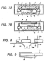
- Fig. 7A illustrates a reproduction state of a disc 6
- Fig. 7B illustrates a loading or unloading state of the disc 6.
- a reproduction unit 1 shown in Figs. 7A and 7B supports a pickup 1c and a disc motor 1a.
- a turntable 1b fixed to a rotary shaft of the disc motor 1a supports the disk 6 which is rotated by the disc motor 1a.
- the pickup 1c is transported in a disc radial direction by a pickup transport unit (not shown) supported by the reproduction unit chassis 1.
- the reproduction unit chassis 1 supports mechanisms necessary for the reproduction of a disc.
- the chassis 1 is supported by side walls 5 of the main chassis via damper mechanisms 2 constituted of coil springs and dampers.
- the reproduction unit chassis 1 In the reproduction state shown in Fig. 7A , the reproduction unit chassis 1 is supported in a floating state by the damper mechanisms 2 and moves relative to the main chassis. In order to allow a sufficient relative motion of the reproduction unit chassis 1, the chassis 1 is disposed in its natural state by providing upper and lower spaces A and B.
- a lock mechanism 3 fixes the reproduction unit chassis 1 at a neutral position of the damper mechanisms 2 and a disc loading/unloading mechanism 4 is raised to load or unload the disc 6 so that the disc 6 does, not abut on a projection supported by the reproduction unit chassis 1 such as the turntable 1b while the disc 6 is transported.
- FIG. 8 An example of the disc loading/unloading mechanism of a conventional vehicle mount disc player is shown in Fig. 8 .
- a disc recording/reproducing unit is supported by a floating chassis (reproduction unit chassis) which is supported by a main chassis via unrepresented damper mechanisms.
- a housing (main chassis) 52 has a fixed disc guide 53 extending inward from a disc insert port 52a.
- a disc 51 inserted into the disc insert port 52a is transported to a recording/reproducing position by an unrepresented feed roller, or the disc 51 at the recording/reproducing position is transported to a position extending outward from the disc insert port 52a.
- a disc used with the vehicle mount disc player is accommodated in a cartridge on which a shutter 58 is amounted in a slidable state as shown in Fig. 9 .
- the shutter 58 opens and closes a window of the cartridge. In some state, the end of the shutter 58 becomes open and extends downward from the cartridge bottom surface by a distance C' shown in Fig. 9 . Therefore, as shown in Fig. 8 , the fixed disc guide 53 and a floating disc guide 54 are each provided with slanted guide portions 53a and 55 to smoothly guide the disc 6.
- the slanted guide portions 53a and 55 are disposed facing each other. It is therefore necessary to set a distance B' shown in Fig. 8 between opposing ends of the slanted guide portions 53a and 55 in order to allow a motion stroke of the floating chassis. The distance of transporting the disc 6 becomes long and the depth of the apparatus becomes large.
- a vehicle mount disc player according to claim and a method of operating a vehicle mount disc player according to claim 1.
- Preferred embodiments of the invention are claimed in the subclaims.
- a disc loading/unloading mechanism for loading/unloading a disc by guiding the disc along a fixed disc guide fixed to a housing and a floating disc guide fixed to a floating chassis, wherein a slanted guide portion of the fixed disc guide and slanted guide portions of the floating disc guide are disposed at different positions along a direction perpendicular to a disc transport direction and at overlapping positions along the disc transport direction, the slanted guide portions being spaced apart by a distance allowing a motion stroke of the floating chassis.
- another slanted guide portion is provided having a larger slant angle or a shorter length than a slant angle or a length of each of the slanted guide portions disposed at different positions along a direction perpendicular to a disc transport direction, the other slanted guide portion being disposed spaced apart from an opposing slanted guide portion by a distance allowing a motion stroke of the floating chassis.
- FIGs. 1A to 1C are schematic cross sectional views showing the structure of a vehicle mount disc player according to a first embodiment of the invention.
- Fig. 1A illustrates a reproduction state of a disc 6
- Fig. 1C illustrates a loading or unloading state of the disc 6.
- Fig. 1B illustrates a transition state from the reproduction state to the loading or unloading state.
- a reproduction unit 1 shown in Figs. 7A to 7C supports mechanisms such as a pickup 1c and a disc motor 1a necessary for the reproduction of the disc, as described with the conventional disc player.
- the chassis 1 is supported by side walls 5 of the main chassis via damper mechanisms 2 constituted of coil springs and dampers.
- the reproduction unit chassis 1 In the reproduction state shown in Fig. 1A , the reproduction unit chassis 1 is supported in a floating state by the damper mechanisms 2 and moves relative to the main chassis. In order to allow a sufficient relative motion of the reproduction unit chassis 1, the chassis 1 is disposed in its natural state generally at the center position of the main chassis.
- a lock mechanism 3 pushes downward the reproduction unit chassis 1, and as shown in Fig. 1C , lifts a disc loading/unloading mechanism 4.
- Locking the reproduction unit chassis 1 and lifting the disc loading/unloading mechanism 4 are performed by the lock mechanism 3 as illustrated in Fig. 2 .
- a relative motion between the lock mechanism 3, a shaft 1d of the reproduction unit chassis 1 and a shaft 4a of the disc loading/unloading mechanism 4 is illustrated in Fig. 2 .
- the lock mechanism 3 For the transition from the reproduction state to the loading or unloading state, the lock mechanism 3 first lowers the shaft 1d to lower the reproduction unit chassis 1, and then raises the shaft 4a to lift the disc loading/unloading mechanism 4. For the transition from the loading or unloading state to the reproduction state, then above operations are reversed. With such operations, a wasteful space as in the conventional disc player can be removed in the loading or unloading state and the disc player can be thinned.
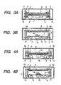
- Figs. 3A and 3B are schematic cross sectional views showing the structure of a vehicle mount disc player according to a second embodiment of the invention.
- Fig. 3A illustrates a reproduction state of the disc 6
- Fig. 3B illustrates a loading or unloading state of the disc 6.
- damper mechanisms 2 support a reproduction unit chassis along an up/down direction
- the other structures are the same as those of the first embodiment, and the detailed description thereof is omitted.
- Figs. 4A and 4B are schematic cross sectional views showing the structure of a vehicle mount disc player according to a third embodiment of the invention.
- Fig. 4A illustrates a reproduction state of the disc 6, and
- Fig. 4B illustrates a loading or unloading state of the disc 6.
- a lock mechanism 3 is disposed outside of side walls 5 of a main chassis.
- the other structures are the same as those of the second embodiment, and the detailed description thereof is omitted.
- a vehicle mount disc player of a lateral mount type have been described.
- the invention is also applicable to a vehicle mount disc player of a vertical mount type.
- the position of the disc loading/unloading mechanism may not be changed by only pushing downward the reproduction unit chassis.
- the disc loading/unloading mechanism is separated from the reproduction unit chassis by using a peripheral space near the reproduction unit chassis in the reproduction state. Accordingly, the dead space in the loading or unloading state is not present and the disc player can be made compact. Furthermore, the conventional damper mechanisms can be used and the damper characteristics are not degraded.
- a plurality of disc players may by accommodated in a standard container for accommodating a single conventional disc player.
- Inexpensive electronic components of a large height can be used.
- FIG. 5 is a plan view showing the main part of a disc loading/unloading mechanism according to an embodiment of the invention
- Fig. 6 is an enlarged cross sectional view showing the main part of the disc loading/unloading mechanism.
- a disc recording/reproducing unit is supported by a floating chassis (reproduction unit chassis 1) which is supported by a main chassis via damper mechanisms such as shown in Figs. 1A to 1C .
- a floating disc guide 54 for guiding the disc is fixed to said floating chassis.
- a housing (main chassis) 52 has a fixed disc guide 53 extending inward from a disc insert port 52a.
- the disc 6 inserted into the disc insert port 52a is transported to a recording/reproducing position by an unrepresented feed roller, or the disc 6 at the recording/reproducing position is transported to a position extending outward from the disc insert port 52a.
- the fixed disc guide 53 is provided with a slanted guide portion 53a for guiding the disc 6.
- the floating disc guide 54 is provided with slanted guide portions 55a and 55c at opposite sides and with a slanted guide portion 55b at the central area.
- An angle between each of the slanted guide portions 55a and 55c and the horizontal plane is smaller than an angle between the slanted guide portion 55b and the horizontal plane.
- the slanted guide portions 55a and 55c extend overlapping the slanted guide portion 55b in the transport direction of the disc 6.
- the angle between the slanted guide potion 55b and the horizontal plane is larger than the angle between each of the slanted guide portions 55a and 55c and the horizontal plane, and the end of the slanted guide portion 55b is spaced by a distance A' from the end of the slanted angle portion 53a in order to allow a motion stroke of the floating chassis.
- the opposite sides of the slanted guide portion 53a are also spaced from the opposing sides of the slanted guide portions 55a and 55c to allow a motion stroke of the floating chassis.
- the slanted guide portions 53a, 55a and 55b are disposed at the positions overlapping each other along the transport direction of the disc 6, the disc transport length can be shortened and the disc player can be made compact. Since the slanted guide portions 53a, 55a and 55b are disposed at different positions along a direction perpendicular to the disc transport direction, they can be disposed spaced apart by a distance allowing the motion stroke of the floating chassis.
- the invention is not limited only to the above embodiment.
- the slanted guide portions disposed at different positions along a direction perpendicular to the disc transport direction may be disposed at opposite sides of the fixed disc guide. Any combination of positions long the width direction perpendicular to the disc transport direction may be used. Instead of setting a larger slant angle of the slanted guide portion 55b, the length of this portion may be shortened.
- the slanted guide portions of the fixed disc guide fixed to the main chassis and the floating disc guide fixed to the floating chassis are disposed at overlapping positions along a disc transport direction. Therefore, a disc transport length can be shortened and the disc player can be made compact.
Landscapes
- Feeding And Guiding Record Carriers (AREA)
- Automatic Disk Changers (AREA)
Description
- The present invention relates to a vehicle mount disc player whose reproduction unit chassis is supported in a floating state by damper mechanisms, and more particularly to a lock position and movement of the reproduction unit and the movement of a disc loading/unloading mechanism when a disc is loaded or unloaded, to a disc loading/unloading mechanism, as well as to a method of operating the disc player.
- An example of a conventional vehicle mount disc player whose reproduction unit chassis is supported in a floating state on a main chassis by damper mechanisms, will be described with reference to
Figs. 7A and 7B. Fig. 7A illustrates a reproduction state of adisc 6, andFig. 7B illustrates a loading or unloading state of thedisc 6. - A
reproduction unit 1 shown inFigs. 7A and 7B supports apickup 1c and adisc motor 1a. Aturntable 1b fixed to a rotary shaft of thedisc motor 1a supports thedisk 6 which is rotated by thedisc motor 1a. Thepickup 1c is transported in a disc radial direction by a pickup transport unit (not shown) supported by thereproduction unit chassis 1. In the above manner, thereproduction unit chassis 1 supports mechanisms necessary for the reproduction of a disc. In order to prevent external vibrations from being transmitted to thereproduction unit chassis 1, thechassis 1 is supported byside walls 5 of the main chassis viadamper mechanisms 2 constituted of coil springs and dampers. - In the reproduction state shown in
Fig. 7A , thereproduction unit chassis 1 is supported in a floating state by thedamper mechanisms 2 and moves relative to the main chassis. In order to allow a sufficient relative motion of thereproduction unit chassis 1, thechassis 1 is disposed in its natural state by providing upper and lower spaces A and B. - As shown in
Fig. 7B , when thedisc 6 is loaded or unloaded, alock mechanism 3 fixes thereproduction unit chassis 1 at a neutral position of thedamper mechanisms 2 and a disc loading/unloading mechanism 4 is raised to load or unload thedisc 6 so that thedisc 6 does, not abut on a projection supported by thereproduction unit chassis 1 such as theturntable 1b while thedisc 6 is transported. - In the conventional vehicle mount disc player described above, when the
disc 6 is loaded or unloaded, thereproduction unit chassis 1 is fixed at the neutral position of thedamper mechanisms 2. Therefore, the lower space B under thereproduction unit chassis 1 becomes a wasteful space and the disc player cannot be thinned. - An example of the disc loading/unloading mechanism of a conventional vehicle mount disc player is shown in
Fig. 8 . A disc recording/reproducing unit is supported by a floating chassis (reproduction unit chassis) which is supported by a main chassis via unrepresented damper mechanisms. - A housing (main chassis) 52 has a
fixed disc guide 53 extending inward from adisc insert port 52a. Adisc 51 inserted into thedisc insert port 52a is transported to a recording/reproducing position by an unrepresented feed roller, or thedisc 51 at the recording/reproducing position is transported to a position extending outward from thedisc insert port 52a. - A disc used with the vehicle mount disc player is accommodated in a cartridge on which a
shutter 58 is amounted in a slidable state as shown inFig. 9 . Theshutter 58 opens and closes a window of the cartridge. In some state, the end of theshutter 58 becomes open and extends downward from the cartridge bottom surface by a distance C' shown inFig. 9 . Therefore, as shown inFig. 8 , thefixed disc guide 53 and afloating disc guide 54 are each provided withslanted guide portions disc 6. - With the conventional disc loading/unloading mechanism described above, the
slanted guide portions Fig. 8 between opposing ends of theslanted guide portions disc 6 becomes long and the depth of the apparatus becomes large. - It is an object of the present invention to provide a vehicle mount disc player whose height is made low by removing a wasteful space in a disc loading/unloading state.
- It is a further aspect of the present invention to provide a disc loading/unloading mechanism for a vehicle mount disc player capable of shortening a depth of the player and of shortening a disc transport distance.
- From
US 5,166,918 a disc player is known, wherein, when a disc loaded or unloaded, a chassis is moved downwards and a holder is moved upwards. The movements of the chassis and the holder are performed simultaneously and in opposite directions due to a parallel configuration of linkage levers. - According to the present invention, there is provided a vehicle mount disc player according to claim and a method of operating a vehicle mount disc player according to
claim 1. Preferred embodiments of the invention are claimed in the subclaims. - According to the further aspect of the present invention, a disc loading/unloading mechanism for loading/unloading a disc by guiding the disc along a fixed disc guide fixed to a housing and a floating disc guide fixed to a floating chassis, is provided wherein a slanted guide portion of the fixed disc guide and slanted guide portions of the floating disc guide are disposed at different positions along a direction perpendicular to a disc transport direction and at overlapping positions along the disc transport direction, the slanted guide portions being spaced apart by a distance allowing a motion stroke of the floating chassis.
- In the disc loading/unloading mechanism, another slanted guide portion is provided having a larger slant angle or a shorter length than a slant angle or a length of each of the slanted guide portions disposed at different positions along a direction perpendicular to a disc transport direction, the other slanted guide portion being disposed spaced apart from an opposing slanted guide portion by a distance allowing a motion stroke of the floating chassis.
-
-
Figs. 1A to 1C are schematic cross sectional views showing the structure of a vehicle mount disc player according to a first embodiment of the invention. -
Fig. 2 is a schematic side view of the vehicle mount disc player, illustrating the operation of a lock mechanism. -
Figs. 3A and 3B are schematic cross sectional views showing the structure of a vehicle mount disc player according to a second embodiment of the invention. -
Figs. 4A and 4B are schematic cross sectional views showing the structure of a vehicle mount disc player according to a third embodiment of the invention. -
Fig. 5 is a plan view showing the main part of a disc loading/unloading mechanism according to an embodiment of the invention. -
Fig. 6 is an enlarged cross sectional view showing the main part of the disc loading/unloading mechanism. -
Figs. 7A and 7B are cross sectional views of a conventional vehicle mount disc player. -
Fig. 8 is a cross sectional view showing another example of the disc loading/unloading mechanism. -
Fig. 9 is a side view illustrating a disc to be loaded or unloaded by the disc loading/unloading mechanism. - A vehicle mount disc player according to an embodiment of the invention, will be described with reference to the accompanying drawings.
Figs. 1A to 1C are schematic cross sectional views showing the structure of a vehicle mount disc player according to a first embodiment of the invention.Fig. 1A illustrates a reproduction state of adisc 6, andFig. 1C illustrates a loading or unloading state of thedisc 6.Fig. 1B illustrates a transition state from the reproduction state to the loading or unloading state. - A
reproduction unit 1 shown inFigs. 7A to 7C supports mechanisms such as apickup 1c and adisc motor 1a necessary for the reproduction of the disc, as described with the conventional disc player. In order to prevent external vibrations from being transmitted to thereproduction unit chassis 1, thechassis 1 is supported byside walls 5 of the main chassis viadamper mechanisms 2 constituted of coil springs and dampers. - In the reproduction state shown in
Fig. 1A , thereproduction unit chassis 1 is supported in a floating state by thedamper mechanisms 2 and moves relative to the main chassis. In order to allow a sufficient relative motion of thereproduction unit chassis 1, thechassis 1 is disposed in its natural state generally at the center position of the main chassis. - As shown in
Fig. 1B , when thedisc 6 is loaded or unloaded, alock mechanism 3 pushes downward thereproduction unit chassis 1, and as shown inFig. 1C , lifts a disc loading/unloading mechanism 4. - Locking the
reproduction unit chassis 1 and lifting the disc loading/unloading mechanism 4 are performed by thelock mechanism 3 as illustrated inFig. 2 . A relative motion between thelock mechanism 3, ashaft 1d of thereproduction unit chassis 1 and ashaft 4a of the disc loading/unloading mechanism 4 is illustrated inFig. 2 . - For the transition from the reproduction state to the loading or unloading state, the
lock mechanism 3 first lowers theshaft 1d to lower thereproduction unit chassis 1, and then raises theshaft 4a to lift the disc loading/unloading mechanism 4. For the transition from the loading or unloading state to the reproduction state, then above operations are reversed. With such operations, a wasteful space as in the conventional disc player can be removed in the loading or unloading state and the disc player can be thinned. -
Figs. 3A and 3B are schematic cross sectional views showing the structure of a vehicle mount disc player according to a second embodiment of the invention.Fig. 3A illustrates a reproduction state of thedisc 6, andFig. 3B illustrates a loading or unloading state of thedisc 6. In this embodiment,damper mechanisms 2 support a reproduction unit chassis along an up/down direction The other structures are the same as those of the first embodiment, and the detailed description thereof is omitted. -
Figs. 4A and 4B are schematic cross sectional views showing the structure of a vehicle mount disc player according to a third embodiment of the invention.Fig. 4A illustrates a reproduction state of thedisc 6, andFig. 4B illustrates a loading or unloading state of thedisc 6. In this embodiment, alock mechanism 3 is disposed outside ofside walls 5 of a main chassis. The other structures are the same as those of the second embodiment, and the detailed description thereof is omitted. - In the above embodiments, a vehicle mount disc player of a lateral mount type have been described. The invention is also applicable to a vehicle mount disc player of a vertical mount type. When a disc is loaded or unloaded, the position of the disc loading/unloading mechanism may not be changed by only pushing downward the reproduction unit chassis.
- According to the vehicle mount disc player of this invention, the disc loading/unloading mechanism is separated from the reproduction unit chassis by using a peripheral space near the reproduction unit chassis in the reproduction state. Accordingly, the dead space in the loading or unloading state is not present and the disc player can be made compact. Furthermore, the conventional damper mechanisms can be used and the damper characteristics are not degraded.
- Since the mechanical structure can be thinned, a plurality of disc players may by accommodated in a standard container for accommodating a single conventional disc player. Inexpensive electronic components of a large height can be used.
- A disc loading/unloading mechanism for a vehicle mount disc player according to an embodiment of the invention will be described with referent to
Figs. 5 and 6. Fig. 5 is a plan view showing the main part of a disc loading/unloading mechanism according to an embodiment of the invention, andFig. 6 is an enlarged cross sectional view showing the main part of the disc loading/unloading mechanism. When this disc loading/unloading mechanism is used, thedisc 51 described with the conventional example shown inFig. 8 is loaded or unloaded. - A disc recording/reproducing unit is supported by a floating chassis (reproduction unit chassis 1) which is supported by a main chassis via damper mechanisms such as shown in
Figs. 1A to 1C . A floatingdisc guide 54 for guiding the disc is fixed to said floating chassis. - A housing (main chassis) 52 has a fixed
disc guide 53 extending inward from adisc insert port 52a. Thedisc 6 inserted into thedisc insert port 52a is transported to a recording/reproducing position by an unrepresented feed roller, or thedisc 6 at the recording/reproducing position is transported to a position extending outward from thedisc insert port 52a. - The fixed
disc guide 53 is provided with aslanted guide portion 53a for guiding thedisc 6. The floatingdisc guide 54 is provided with slantedguide portions slanted guide portion 55b at the central area. An angle between each of the slantedguide portions slanted guide portion 55b and the horizontal plane. The slantedguide portions guide portion 55b in the transport direction of thedisc 6. The angle between theslanted guide potion 55b and the horizontal plane is larger than the angle between each of the slantedguide portions guide portion 55b is spaced by a distance A' from the end of the slantedangle portion 53a in order to allow a motion stroke of the floating chassis. The opposite sides of the slantedguide portion 53a are also spaced from the opposing sides of the slantedguide portions - Since the slanted
guide portions disc 6, the disc transport length can be shortened and the disc player can be made compact. Since the slantedguide portions - The invention is not limited only to the above embodiment. For example, the slanted guide portions disposed at different positions along a direction perpendicular to the disc transport direction, may be disposed at opposite sides of the fixed disc guide. Any combination of positions long the width direction perpendicular to the disc transport direction may be used. Instead of setting a larger slant angle of the slanted
guide portion 55b, the length of this portion may be shortened. - According to the disc loading/unloading mechanism of this invention, the slanted guide portions of the fixed disc guide fixed to the main chassis and the floating disc guide fixed to the floating chassis are disposed at overlapping positions along a disc transport direction. Therefore, a disc transport length can be shortened and the disc player can be made compact.
Claims (13)
- A method of operating a vehicle mount disc player having a reproduction unit chassis (1) supported in a floating state by a main chassis via a damper mechanism (2), wherein a reproduction state is shifted to a loading state or unloading state, said reproduction unit chassis (1) in a floating state relative to said main chassis is moved downward in an axial direction of a turntable (1b) so as to lock said reproduction unit (1) with said main chassis, and a disc loading/unloading mechanism (4), in a floating state relative to said main chassis, is moved upward in said axial direction,
characterized in that
said movement of said disc loading/unloading mechanism (4) is performed after completion of said movement of said reproduction unit chassis (1). - The method according to claim 1, characterized in that
said movements are performed by means (3) of the disc player and in that
said disc loading/unloading mechanism (4) is moved downward before the upward movement thereof, when the reproduction state is shifted to the loading state or unloading state. - The method according to claim 2, characterized in that said damper mechanism (2) supports said reproduction unit chassis (1) at sides of the reproduction unit chassis (1).
- The method according to claim 2, characterize in that said damper mechanism (2) supports said reproduction unit chassis (1) at a bottom of the reproduction unit chassis (1).
- The method according to claim 4, characterized in that the locking of said reproduction unit chassis (1) with said main chassis is performed by locking means (3) provided inside of a side wall (5) of the main chassis.
- The method according to claim 4, characterized in that the locking of said reproduction unit chassis (1) with said main chassis is performed by locking means (3) provided outside of a side wall (5) of the main chassis.
- A vehicle mount disc player having a reproduction unit chassis (1) supported in a floating state by a main chassis via a damper mechanism (2), comprising locking means (3),
wherein said locking means (3) serves
for moving said reproduction unit chassis (1) and a disc loading/unloading mechanism (4), in a floating state relative-to said main chassis, downward in an axial direction of a turntable (1b),
for locking only said moved reproduction unit chassis (1) with said main chassis, and
for separating said disc loading/unloading mechanism (4) from said locked reproduction unit chassis (1) to move the separated disc loading/unloading mechanism (4) upward in said axial direction. - The vehicle mount disc player according to claim 7, characterized in that the disc loading/unloading mechanism is arranged such that the loading/unloading of a disc (6) is performed by guiding the disc along a fixed disc guide (53) fixed to a housing (52) and a floating disc guide (54) fixed to a floating chassis, wherein a slanted guide portion (53a) of the fixed disc guide and slanted guide portions (55a, 55b, 55c) of the floating disc guide are disposed at different positions along a direction perpendicular to a disc transport direction and at overlapping positions along the disc transport direction, the slanted guide portions (53a, 55a, 55b, 55c) being spaced apart by a distance allowing a motion stroke of the floating chassis.
- The vehicle mount disc player according to claim 8, characterized in that another slanted guide portion is provided having a larger slant angle or a shorter length than a slant angle or a length of each of the slanted guide portions (55a, 55c) disposed at different positions along a direction perpendicular to a disc transport direction, the other slanted guide portion being disposed spaced apart from an opposing slanted guide portion by a distance allowing a motion stroke of the floating chassis.
- The vehicle mount disc player according to claim 9, characterized in that the slanted guide portion (53a) of the fixed disc guide extends from an end of the fixed disc guide, the slanted guide portions of the floating disc guide include a first slanted portion (55b) facing the slanted guide portion (53a) of the fixed disc guide over a whole width of the slanted guide portion, and second slanted portions (55a, 55c) formed on both sides of the first slanted portion, therein the slanted guide portion (53a) of the fixed disc guide is positioned between the second slanted portions without contacting the second slanted portions.
- The method according to any of the claims 1-6, characterized in that the loading/unloading of a disc (6) is performed by guiding the disc along a fixed disc guide (53) fixed to a housing (52) and a floating disc guide (54) fixed to a floating chassis, wherein a slanted guide portion (53a) of the fixed disc guide and slanted guide portions (55a, 55b, 55c) of the floating disc guide are disposed at different positions along a direction perpendicular to a disc transport direction and at overlapping positions along the disc transport direction, the slanted guide portions (53a, 55a, 55b, 55c) being spaced apart by a distance allowing a motion stroke of the floating chassis.
- The method according to claim 11, characterized in that another slanted guide portion is provided having a larger slant angle or a shorter length than a slant angle or a length of each of the slanted guide portions (55a, 55c) disposed at different positions along a direction perpendicular to a disc transport direction, the other slanted guide portion being disposed spaced apart from an opposing slanted guide portion by a distance allowing a motion stroke of the floating chassis.
- The method according to claim 12, characterized in that the slanted guide portion (53a) of the fixed disc guide extends from an end of the fixed disc guide, the slanted guide portions of the floating disc guide include a first slanted portion (55b) facing the slanted guide portion (53a) of the fixed disc guide over a whole width of the slanted guide portion, and second slanted portions (55a, 55c) formed on both sides of the first slanted portion, wherein the slanted guide portion (53a) of the fixed disc guide is positioned between the second slanted portions without contacting the second slanted portions.
Applications Claiming Priority (5)
| Application Number | Priority Date | Filing Date | Title |
|---|---|---|---|
| JP9242154A JP2981450B2 (en) | 1997-08-22 | 1997-08-22 | In-vehicle disk player |
| JP24215497 | 1997-08-22 | ||
| JP9303487A JP2981452B2 (en) | 1997-10-17 | 1997-10-17 | Disc insertion / ejection mechanism |
| JP30348797 | 1997-10-17 | ||
| PCT/JP1998/003605 WO1999010890A2 (en) | 1997-08-22 | 1998-08-12 | Disc player mounted on vehicle |
Publications (2)
| Publication Number | Publication Date |
|---|---|
| EP1004118A2 EP1004118A2 (en) | 2000-05-31 |
| EP1004118B1 true EP1004118B1 (en) | 2009-02-11 |
Family
ID=26535635
Family Applications (1)
| Application Number | Title | Priority Date | Filing Date |
|---|---|---|---|
| EP98937805A Expired - Lifetime EP1004118B1 (en) | 1997-08-22 | 1998-08-12 | Disc player mounted on vehicle |
Country Status (9)
| Country | Link |
|---|---|
| US (2) | US6772425B1 (en) |
| EP (1) | EP1004118B1 (en) |
| KR (1) | KR100415869B1 (en) |
| CN (2) | CN100388385C (en) |
| DE (1) | DE69840543D1 (en) |
| ID (1) | ID24589A (en) |
| MY (1) | MY123169A (en) |
| TW (1) | TW388860B (en) |
| WO (1) | WO1999010890A2 (en) |
Families Citing this family (7)
| Publication number | Priority date | Publication date | Assignee | Title |
|---|---|---|---|---|
| JP4099565B2 (en) * | 2000-12-11 | 2008-06-11 | ソニー株式会社 | Disc recording and / or playback device |
| JP2004273173A (en) * | 2003-03-05 | 2004-09-30 | Pioneer Electronic Corp | Contact point structure, electronic equipment, and manufacturing method of contact point structure |
| GB0505300D0 (en) | 2005-03-15 | 2005-04-20 | Level 5 Networks Ltd | Transmitting data |
| GB0506403D0 (en) | 2005-03-30 | 2005-05-04 | Level 5 Networks Ltd | Routing tables |
| US20100192168A1 (en) * | 2007-10-31 | 2010-07-29 | Mitsubishi Electric Corporation | Disc device |
| JP5671273B2 (en) * | 2010-07-14 | 2015-02-18 | 東芝アルパイン・オートモティブテクノロジー株式会社 | Disk unit |
| CN105677291B (en) * | 2016-01-28 | 2019-07-19 | 惠州华阳通用电子有限公司 | A kind of vehicle-mounted broadcast source fast switch over method and device |
Family Cites Families (27)
| Publication number | Priority date | Publication date | Assignee | Title |
|---|---|---|---|---|
| EP0129292B1 (en) * | 1983-06-15 | 1988-10-05 | Koninklijke Philips Electronics N.V. | Disc-record player comprising a disc-loading mechanism and disc holder for use in such a player |
| JPS6038753A (en) | 1983-08-10 | 1985-02-28 | Hitachi Ltd | Magnetic disk driver |
| JPH0610913B2 (en) | 1984-01-12 | 1994-02-09 | ソニー株式会社 | Optical disk player |
| US4669076A (en) * | 1985-10-30 | 1987-05-26 | International Business Machines Corporation | Optical disk drive apparatus with means for accurate disk positioning |
| JPS62195755A (en) | 1986-02-22 | 1987-08-28 | Alps Electric Co Ltd | Disk driver |
| US5172362A (en) * | 1987-05-15 | 1992-12-15 | Hirachi, Ltd. | Recording medium loading mechanism |
| JPS648546A (en) | 1987-06-30 | 1989-01-12 | Seiko Epson Corp | Recording and reproducing device |
| JPS648546U (en) | 1987-07-06 | 1989-01-18 | ||
| JPS63146269A (en) * | 1987-10-12 | 1988-06-18 | Sanyo Electric Co Ltd | Disk loading device |
| BE1002664A3 (en) * | 1988-11-17 | 1991-04-30 | Staar Sa | LOADING, EJECTING AND CENTERING DEVICE FOR DISCS OF DIFFERENT DIAMETERS. |
| US5166918A (en) * | 1989-05-15 | 1992-11-24 | Seiko Epson Corporation | Loading mechanism for disk cartridges with vibration reducing mechanism |
| JP2538386B2 (en) | 1990-04-11 | 1996-09-25 | 三洋電機株式会社 | Disk holding device |
| JP2899357B2 (en) | 1990-04-25 | 1999-06-02 | クラリオン株式会社 | Traverse mechanism for disk-shaped recording media |
| JPH0421946A (en) | 1990-05-15 | 1992-01-24 | Toshiba Corp | Information processor |
| US5351228A (en) * | 1990-09-20 | 1994-09-27 | Ricoh Company Ltd. | Optical disk drive unit |
| JP3006172B2 (en) | 1991-06-10 | 2000-02-07 | ソニー株式会社 | Recording and playback device |
| TW335951U (en) * | 1991-12-27 | 1998-07-01 | Teac Corp | Recording medium loading device |
| JP2785584B2 (en) | 1992-05-11 | 1998-08-13 | 日本電気株式会社 | Optical disk drive |
| JP3276986B2 (en) * | 1992-06-29 | 2002-04-22 | 日本電産コパル株式会社 | Open / close door mechanism |
| US5537377A (en) * | 1993-06-30 | 1996-07-16 | Clarion Co., Ltd. | Information recording and reproducing apparatus |
| JP3406101B2 (en) * | 1994-12-27 | 2003-05-12 | アルパイン株式会社 | Mode switching device for disc player |
| JPH08241554A (en) * | 1995-03-05 | 1996-09-17 | Nakamichi Corp | Disk transfer device |
| US5748595A (en) * | 1995-03-30 | 1998-05-05 | Ricoh Company, Ltd. | Cartridge loading mechanism with a door closing assembly |
| JP3292665B2 (en) | 1996-11-28 | 2002-06-17 | 株式会社クボタ | Threshing equipment |
| JP3812025B2 (en) | 1997-01-16 | 2006-08-23 | 松下電器産業株式会社 | Disk unit |
| JP3855333B2 (en) | 1997-01-16 | 2006-12-06 | 松下電器産業株式会社 | Disk unit |
| CA2232078C (en) * | 1997-03-14 | 2004-05-25 | Sanyo Electric Co., Ltd. | Disk playback device |
-
1998
- 1998-08-11 TW TW087113205A patent/TW388860B/en not_active IP Right Cessation
- 1998-08-12 EP EP98937805A patent/EP1004118B1/en not_active Expired - Lifetime
- 1998-08-12 US US09/486,005 patent/US6772425B1/en not_active Expired - Fee Related
- 1998-08-12 DE DE69840543T patent/DE69840543D1/en not_active Expired - Lifetime
- 1998-08-12 ID IDW20000342A patent/ID24589A/en unknown
- 1998-08-12 WO PCT/JP1998/003605 patent/WO1999010890A2/en not_active Ceased
- 1998-08-12 CN CNB031380956A patent/CN100388385C/en not_active Expired - Fee Related
- 1998-08-12 KR KR10-2000-7001728A patent/KR100415869B1/en not_active Expired - Lifetime
- 1998-08-12 CN CNB988083442A patent/CN100350492C/en not_active Expired - Fee Related
- 1998-08-21 MY MYPI98003820A patent/MY123169A/en unknown
-
2004
- 2004-07-14 US US10/890,172 patent/US7340751B2/en not_active Expired - Fee Related
Also Published As
| Publication number | Publication date |
|---|---|
| US20050102688A1 (en) | 2005-05-12 |
| US7340751B2 (en) | 2008-03-04 |
| CN100388385C (en) | 2008-05-14 |
| HK1027894A1 (en) | 2001-01-23 |
| WO1999010890A2 (en) | 1999-03-04 |
| DE69840543D1 (en) | 2009-03-26 |
| CN1479307A (en) | 2004-03-03 |
| US6772425B1 (en) | 2004-08-03 |
| MY123169A (en) | 2006-05-31 |
| KR20010023106A (en) | 2001-03-26 |
| TW388860B (en) | 2000-05-01 |
| CN1267388A (en) | 2000-09-20 |
| ID24589A (en) | 2000-07-27 |
| CN100350492C (en) | 2007-11-21 |
| WO1999010890A3 (en) | 1999-05-20 |
| HK1061602A1 (en) | 2004-09-24 |
| EP1004118A2 (en) | 2000-05-31 |
| KR100415869B1 (en) | 2004-01-24 |
Similar Documents
| Publication | Publication Date | Title |
|---|---|---|
| KR100318011B1 (en) | Mining tray | |
| US6772425B1 (en) | Disc player mounted on vehicle | |
| US6426935B1 (en) | Supporting structure of floating chassis of disc apparatus | |
| US7003784B2 (en) | Disk apparatus | |
| JPH10269666A (en) | Disc playback device | |
| JPH09231725A (en) | Disc player | |
| US7246362B2 (en) | Optical disk drive allowing for horizontal or vertical installation | |
| HK1061602B (en) | Disc player mounted on vehicle | |
| JPH04362563A (en) | Recording/reproducing device | |
| HK1027894B (en) | Disc player mounted on vehicle | |
| US6285642B1 (en) | Disk device with vibration-insulating mechanism | |
| JP2899357B2 (en) | Traverse mechanism for disk-shaped recording media | |
| EP1313100B1 (en) | Disk holder pop-out preventing device | |
| KR100884656B1 (en) | Disk loading device of disk drive | |
| JPH1166680A (en) | In-vehicle disk player | |
| JP2001110118A (en) | Disk drive device | |
| JPH1011866A (en) | Optical disk autochanger | |
| JPH0567371A (en) | Recording and reproducing device | |
| JP2000173149A (en) | Disk unit | |
| JPH04126363U (en) | Optical pick-up device | |
| KR20050048708A (en) | A disk tray and disk drive using the same | |
| HK1040563B (en) | Supporting structure of floating chassis of disc apparatus | |
| JPH02235254A (en) | Disk player | |
| JPH02301061A (en) | Loading structure of information recording device |
Legal Events
| Date | Code | Title | Description |
|---|---|---|---|
| PUAI | Public reference made under article 153(3) epc to a published international application that has entered the european phase |
Free format text: ORIGINAL CODE: 0009012 |
|
| 17P | Request for examination filed |
Effective date: 20000210 |
|
| AK | Designated contracting states |
Kind code of ref document: A2 Designated state(s): DE FR GB IT |
|
| GRAP | Despatch of communication of intention to grant a patent |
Free format text: ORIGINAL CODE: EPIDOSNIGR1 |
|
| RAP1 | Party data changed (applicant data changed or rights of an application transferred) |
Owner name: KABUSHIKI KAISHA KENWOOD |
|
| GRAS | Grant fee paid |
Free format text: ORIGINAL CODE: EPIDOSNIGR3 |
|
| GRAA | (expected) grant |
Free format text: ORIGINAL CODE: 0009210 |
|
| AK | Designated contracting states |
Kind code of ref document: B1 Designated state(s): DE FR GB IT |
|
| REG | Reference to a national code |
Ref country code: GB Ref legal event code: FG4D |
|
| REF | Corresponds to: |
Ref document number: 69840543 Country of ref document: DE Date of ref document: 20090326 Kind code of ref document: P |
|
| PLBE | No opposition filed within time limit |
Free format text: ORIGINAL CODE: 0009261 |
|
| STAA | Information on the status of an ep patent application or granted ep patent |
Free format text: STATUS: NO OPPOSITION FILED WITHIN TIME LIMIT |
|
| 26N | No opposition filed |
Effective date: 20091112 |
|
| REG | Reference to a national code |
Ref country code: DE Ref legal event code: R081 Ref document number: 69840543 Country of ref document: DE Owner name: JVC KENWOOD CORPORATION, YOKOHAMA-SHI, JP Free format text: FORMER OWNER: KABUSHIKI KAISHA KENWOOD, HACHIOUJI, TOKIO/TOKYO, JP Effective date: 20120430 |
|
| REG | Reference to a national code |
Ref country code: FR Ref legal event code: TP Owner name: JVC KENWOOD CORPORATION, JP Effective date: 20120705 |
|
| PGFP | Annual fee paid to national office [announced via postgrant information from national office to epo] |
Ref country code: DE Payment date: 20130807 Year of fee payment: 16 |
|
| PGFP | Annual fee paid to national office [announced via postgrant information from national office to epo] |
Ref country code: FR Payment date: 20130808 Year of fee payment: 16 Ref country code: GB Payment date: 20130807 Year of fee payment: 16 |
|
| PGFP | Annual fee paid to national office [announced via postgrant information from national office to epo] |
Ref country code: IT Payment date: 20130820 Year of fee payment: 16 |
|
| REG | Reference to a national code |
Ref country code: DE Ref legal event code: R119 Ref document number: 69840543 Country of ref document: DE |
|
| GBPC | Gb: european patent ceased through non-payment of renewal fee |
Effective date: 20140812 |
|
| PG25 | Lapsed in a contracting state [announced via postgrant information from national office to epo] |
Ref country code: IT Free format text: LAPSE BECAUSE OF NON-PAYMENT OF DUE FEES Effective date: 20140812 |
|
| REG | Reference to a national code |
Ref country code: FR Ref legal event code: ST Effective date: 20150430 |
|
| REG | Reference to a national code |
Ref country code: DE Ref legal event code: R119 Ref document number: 69840543 Country of ref document: DE Effective date: 20150303 |
|
| PG25 | Lapsed in a contracting state [announced via postgrant information from national office to epo] |
Ref country code: DE Free format text: LAPSE BECAUSE OF NON-PAYMENT OF DUE FEES Effective date: 20150303 Ref country code: GB Free format text: LAPSE BECAUSE OF NON-PAYMENT OF DUE FEES Effective date: 20140812 |
|
| PG25 | Lapsed in a contracting state [announced via postgrant information from national office to epo] |
Ref country code: FR Free format text: LAPSE BECAUSE OF NON-PAYMENT OF DUE FEES Effective date: 20140901 |