EP1003580B1 - Injection device - Google Patents
Injection device Download PDFInfo
- Publication number
- EP1003580B1 EP1003580B1 EP98939757A EP98939757A EP1003580B1 EP 1003580 B1 EP1003580 B1 EP 1003580B1 EP 98939757 A EP98939757 A EP 98939757A EP 98939757 A EP98939757 A EP 98939757A EP 1003580 B1 EP1003580 B1 EP 1003580B1
- Authority
- EP
- European Patent Office
- Prior art keywords
- barrel
- connector
- syringe
- injection device
- syringe carrier
- Prior art date
- Legal status (The legal status is an assumption and is not a legal conclusion. Google has not performed a legal analysis and makes no representation as to the accuracy of the status listed.)
- Expired - Lifetime
Links
- 238000002347 injection Methods 0.000 title claims abstract description 42
- 239000007924 injection Substances 0.000 title claims abstract description 42
- 238000010304 firing Methods 0.000 claims abstract description 40
- 238000003780 insertion Methods 0.000 claims description 6
- 230000037431 insertion Effects 0.000 claims description 6
- 230000013011 mating Effects 0.000 claims description 2
- 230000002028 premature Effects 0.000 claims description 2
- 239000002775 capsule Substances 0.000 description 10
- 239000007788 liquid Substances 0.000 description 5
- 239000000843 powder Substances 0.000 description 4
- 239000000126 substance Substances 0.000 description 3
- 230000004888 barrier function Effects 0.000 description 2
- 239000012528 membrane Substances 0.000 description 2
- 238000000034 method Methods 0.000 description 2
- 239000000203 mixture Substances 0.000 description 2
- 230000035515 penetration Effects 0.000 description 2
- 240000007643 Phytolacca americana Species 0.000 description 1
- 230000015572 biosynthetic process Effects 0.000 description 1
- 230000000295 complement effect Effects 0.000 description 1
- 230000006835 compression Effects 0.000 description 1
- 238000007906 compression Methods 0.000 description 1
- 239000003814 drug Substances 0.000 description 1
- 230000000694 effects Effects 0.000 description 1
- 231100001261 hazardous Toxicity 0.000 description 1
- 238000004519 manufacturing process Methods 0.000 description 1
- 239000000463 material Substances 0.000 description 1
- 230000037368 penetrate the skin Effects 0.000 description 1
- 229920003023 plastic Polymers 0.000 description 1
- 239000004033 plastic Substances 0.000 description 1
- 230000000717 retained effect Effects 0.000 description 1
- 239000000243 solution Substances 0.000 description 1
- 230000000007 visual effect Effects 0.000 description 1
- XLYOFNOQVPJJNP-UHFFFAOYSA-N water Substances O XLYOFNOQVPJJNP-UHFFFAOYSA-N 0.000 description 1
Images
Classifications
-
- A—HUMAN NECESSITIES
- A61—MEDICAL OR VETERINARY SCIENCE; HYGIENE
- A61M—DEVICES FOR INTRODUCING MEDIA INTO, OR ONTO, THE BODY; DEVICES FOR TRANSDUCING BODY MEDIA OR FOR TAKING MEDIA FROM THE BODY; DEVICES FOR PRODUCING OR ENDING SLEEP OR STUPOR
- A61M5/00—Devices for bringing media into the body in a subcutaneous, intra-vascular or intramuscular way; Accessories therefor, e.g. filling or cleaning devices, arm-rests
- A61M5/178—Syringes
- A61M5/20—Automatic syringes, e.g. with automatically actuated piston rod, with automatic needle injection, filling automatically
- A61M5/2033—Spring-loaded one-shot injectors with or without automatic needle insertion
-
- A—HUMAN NECESSITIES
- A61—MEDICAL OR VETERINARY SCIENCE; HYGIENE
- A61M—DEVICES FOR INTRODUCING MEDIA INTO, OR ONTO, THE BODY; DEVICES FOR TRANSDUCING BODY MEDIA OR FOR TAKING MEDIA FROM THE BODY; DEVICES FOR PRODUCING OR ENDING SLEEP OR STUPOR
- A61M5/00—Devices for bringing media into the body in a subcutaneous, intra-vascular or intramuscular way; Accessories therefor, e.g. filling or cleaning devices, arm-rests
- A61M5/178—Syringes
- A61M5/20—Automatic syringes, e.g. with automatically actuated piston rod, with automatic needle injection, filling automatically
- A61M2005/2073—Automatic syringes, e.g. with automatically actuated piston rod, with automatic needle injection, filling automatically preventing premature release, e.g. by making use of a safety lock
-
- A—HUMAN NECESSITIES
- A61—MEDICAL OR VETERINARY SCIENCE; HYGIENE
- A61M—DEVICES FOR INTRODUCING MEDIA INTO, OR ONTO, THE BODY; DEVICES FOR TRANSDUCING BODY MEDIA OR FOR TAKING MEDIA FROM THE BODY; DEVICES FOR PRODUCING OR ENDING SLEEP OR STUPOR
- A61M5/00—Devices for bringing media into the body in a subcutaneous, intra-vascular or intramuscular way; Accessories therefor, e.g. filling or cleaning devices, arm-rests
- A61M5/178—Syringes
- A61M5/1782—Devices aiding filling of syringes in situ
-
- A—HUMAN NECESSITIES
- A61—MEDICAL OR VETERINARY SCIENCE; HYGIENE
- A61M—DEVICES FOR INTRODUCING MEDIA INTO, OR ONTO, THE BODY; DEVICES FOR TRANSDUCING BODY MEDIA OR FOR TAKING MEDIA FROM THE BODY; DEVICES FOR PRODUCING OR ENDING SLEEP OR STUPOR
- A61M5/00—Devices for bringing media into the body in a subcutaneous, intra-vascular or intramuscular way; Accessories therefor, e.g. filling or cleaning devices, arm-rests
- A61M5/50—Devices for bringing media into the body in a subcutaneous, intra-vascular or intramuscular way; Accessories therefor, e.g. filling or cleaning devices, arm-rests having means for preventing re-use, or for indicating if defective, used, tampered with or unsterile
- A61M5/5086—Devices for bringing media into the body in a subcutaneous, intra-vascular or intramuscular way; Accessories therefor, e.g. filling or cleaning devices, arm-rests having means for preventing re-use, or for indicating if defective, used, tampered with or unsterile for indicating if defective, used, tampered with or unsterile
Definitions
- This invention relates to injection devices.
- Document WO A 94/11041 discloses an injection device according to the preamble of claim 1 which comprises a barrel with a syringe carrier axially movable therein.
- the syringe carrier is connectable to a firing device, which in use ensures the automatic advancement of the syringe plunger and injection of the medicament.
- the syringe carrier is advanced with respect to the barrel by the user providing pressure on the firing device to overcome the resistance of a detent. Thus, insertion of the needle is achieved.
- Document FR A 1257066 describes a device which achieves automatic needle insertion in combination with automatic injection. It does not, however, comprise a separate injection device which can be connected to a firing device.
- the syringe with its needle is thrown away into a guarded enclosure, for obvious safety reasons. But removing it from a re-usable device that first fires the syringe forwards to make the needle penetrate, then pushes the syringe piston forwards to eject the dose, and which finally withdraws the syringe and needle, can itself be hazardous and time-consuming.
- the device in two parts, one being a re-usable firing mechanism with a plunger that can be released to spring forwards, and the other being a housing and guide for the syringe to which the firing mechanism can be temporarily attached, it becomes possible to contemplate throwing away this other part (still containing a syringe).
- an injection device comprising a barrel, a syringe carrier within the barrel axially movable between a rearward position, in which the needle of a syringe carried thereby is retracted within the forward end of the barrel and a forward position, in which the needle projects from the forward end of the barrel, spring means urging the syringe carrier to revert to a rearward position after removal of the injection device from the skin, and a removable locking element inserted laterally into the device to prevent premature operation, characterised in that a connector is provided at the rear end of the barrel for attachment and detachment of a firing device whose firing member, when released, acts on the piston in the syringe to urge the syringe forwards and then to eject a dose, the connector having limited axial movement with respect to the carrier that, on actuation of the firing device, the whole carrier with its syringe can move forwards to provide needle insertion, and in that, on removal of the locking element
- the device is manifestly in a non-usable condition as long as the locking element is in place. If it has been removed, it signifies that the device has been used and should be discarded. It is of course not just a visual signal; it is primarily a physical barrier to operation.
- the connector and the syringe carrier finish at respective positions where their detents that were originally engaged by the locking element are no longer in registry with the aperture in the barrel through which the locking element was entered.
- the connector may have a snap engagement with a detent internal of the barrel designed to capture the connection in its after use position, while the spring means can be designed to urge the carrier to the rear of its locked position.
- the spring means may be arranged to be partially energised in the initial locked position, so that when the locking element is removed, the spring means will urge the syringe carrier rearwardly, bringing the tip of the needle further back into the barrel from a nearly projecting position which enables the cap to be removed.
- the carrier may be arranged to act on the connector to push that rearwardly, although not so far that it is captured in its ultimate after use position.
- a snap engagement element on the connector may be located such that it is rendered inoperative before firing of the device by interengagement of the syringe carrier and the connector, said element in that inoperative state forming a stop that limits rearward movement of the connector.
- the spring means will act through the carrier, the syringe and the firing member to cause the reversion of the connector to its rearward, captive position, the axial relationship between the syringe carrier and the connector having changed and removed the interengagement that rendered the snap engagement element inoperative and limited the rearward movement before firing.
- the attachment of the firing device to the connector is by mating screw threads, the connector being restrained against rotation with respect to the barrel.
- the connector may be a stepped tube, the smaller diameter portion at the rear end providing a socket to receive the firing device, the internal forward facing shoulder formed by the step providing an abutment for the rear end of the syringe carrier, and the external, rearward facing shoulder formed by the step providing an abutment for engagement with a locking ring, fitted to the rear end of the barrel, when the connector is at its after use position.
- the syringe carrier may have its limit of forward movement defined by an abutment internal of the barrel. This can be provided by the rear end of guide means for keeping the syringe carrier co-axial with the barrel, and against which a flange at the rear end of the syringe carrier will abut.
- the flange may also provide the detent in which the locking element engages.
- the spring means is conveniently a helical spring surrounding a needle unit to engage the forward end of the syringe carrier and reacting against an abutment within the forward end of the barrel.
- the forward end of the barrel is equipped internally with barbs which point towards the mouth. They will allow projection of the needle and removal of the needle cap, but make it virtually impossible to poke a finger in and contact the retracted needle.
- the roots of the barbs conveniently provide the abutment for the spring.
- Such an injection device is primarily intended for use with a syringe containing a two component dose, these components having to be mixed immediately before injection.
- One component is a liquid (which may simply be water) already within the syringe, while the other component is a powder, to be dispersed in or made into a solution with the liquid.
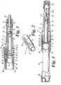
- the device has a barrel 1 with a tapered forward part 2 and a generally cylindrical rear part 3. Telescoped into this rear part 3 there is a stepped connector tube 4 whose reduced diameter rear end portion 5 forms a screw-threaded socket. At the midlength there is an external, rearwardly facing shoulder 6 and an internal, forwardly facing shoulder 7. Just forward of these shoulders, the forward end portion 8 has an aperture 9 whose purpose is described later. Actually, as best seen in Figure 2, this aperture 9 is the base of a narrow U-shaped slot 10 which forms a finger 11 effectively hinged to the portion 8 at its forward end by the resilient flexibility of the plastics material of which it is formed. At the rear end, the finger 11 has an outwardly projecting lug 12.
- the tube 4 is prevented from rotating with respect to the barrel 1 by a spline 13 on the interior of the barrel engaged in a groove in the portion 8.
- the barrel is formed with internal guide ribs 14 over most of the tapered forward part 2, these terminating in rearwardly facing shoulders 15.
- the barrel is also extended rearwardly a short distance by a ring 16 which sleeves between the part 3 and the reduced diameter portion 5 of the tube 4, being retained by a snap fit rib and groove arrangement 17 and having a shoulder 18 abutting against the rear end of the barrel.
- the ring 16 has a forwardly projecting tongue 19 with an aperture 20 and a bevelled end.
- a syringe 21 comprising a capsule 22 with a needle unit 23 at its forward end, the actual needle 23A initially being encased by a cap 24.
- the capsule 22 is enclosed and carried by a sleeve 25 which has an outwardly projecting rim 26 at its rear end, locally thickened to accommodate a notch 27 which registers with the aperture 9 when the rear end of the sleeve 25 is up against the shoulder 7.
- the sleeve 25 has inturned flanges 28 and 29, the rear one 28 providing an abutment for the base of the needle unit 23 and the forward one 29 being U-shaped so that the base of the needle assembly can be entered laterally.
- a helical spring 30 abuts the flange 29 and its forward end engages a guide formation 31 comprising several fingers, symmetrically arranged around the axis of the barrel to form barbs pointing inwards and forwards to terminate in the mouth of the barrel 1.
- These barbs can flex as necessary to allow the cap 24 to be extracted, and they do not impede the projection of the needle 23A. But they do provide an effective barrier to finger penetration.
- the mouth of the barrel is surrounded by a nose piece 32, which may be removed to increase the depth of penetration of the needle into the patient.
- a T-shaped locking member 34 has a short stem 35 and a long asymmetrical cross member 36, and the stem 35 is inserted through the apertures 33 and 9 for its tip to engage in the notch 27 while the cross member 36 lies lengthways closely against the barrel, extending over the beginning of the tapered portion 2 and so affording a gap by which it can be prised away.
- this locking member 34 ensures that the syringe carrier 25 is positively held against any longitudinal movement. It also holds the connector tube 4 with its forward end abutting the shoulders 15.
- This device is designed to be fitted to a known firing mechanism 37 which will not be described in detail. But it has a trigger button 38 at its rear end which, when operated, projects a plunger 39 from its forward end, and it screws into the socket 5. Preferably, the button 38 will have a safe position from which it has to be twisted before it can be pressed to release the plunger.
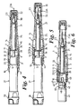
- the nose-piece 32 is then applied to the skin and the firing mechanism 37 pressed forwards, telescoping into the barrel until the tube 4 is arrested by coming up against the shoulders 15 again. This brings the tip of the needle 23A back into the mouth of the barrel, but not quite projecting.
- the button 38 is pressed to fire the plunger 39 forwards. This rapidly pushes the syringe assembly forwards to project the needle 23 and penetrate the skin.
- the spring 30 is of course compressed, being weaker than that of the firing device.
- the plunger 39 carries on to urge the piston (not shown) within the capsule 22 forwards to eject the dose. This is the position of Figure 4.
- the locking element 34 engages both the connector 4 and the syringe carrier 25 to hold them rigid with the barrel. This is preferred, since it makes insertion of the syringe 21 and attachment of the firing mechanism simple and certain. However, the device could be made inoperative by locking either the connector 4 or the syringe carrier 25, particularly the latter.
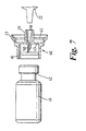
- the vial adaptor 40 (which does not form part of the current invention) is provided to simplify the process of preparing the syringe 21.
- the capsule 22 contains a liquid
- a vial 41 contains a substance, such as a lyophilised powder occupying only a fraction of the space within the vial.
- the dose to administered is a mixture of the liquid and the substance, and so the latter has to be transferred to the syringe.
- the vial 41 has a neck 42 across the end of which is a membrane which initially seals in the powder.
- the adaptor 40 is, in effect, two cups base-to-base, and one cup 43 is adapted to snap over the ring 16, which is provided with an annular groove 44 to receive a rib 45 on the inside of that cup.
- the other cup 46 is adapted to receive and retain, by a tight push fit or a snap-in action for example, the neck 42 of the vial 41.
- the common base 47 of the cups has a small central aperture 48 with a wide co-axial tubular spigot 49 on the side of the cup 43, and a narrow co-axial tubular spigot 50 on the side of the cup 46.
- This spigot has a sharp free end, for example by making it oblique to the axis, while the larger spigot 49 has an internal Luer taper to receive the needle-less forward end or neck of the syringe capsule 22.
- the piston within the capsule has a screw threaded socket on its rear facing side to receive a removable piston rod, which is fitted for the charging process as follows.
- the neck 42 of the vial 41 is plugged into the cup 43 and then the neck of the capsule 22 is plugged into the spigot 49, this action causing the spigot 50 to pierce the membrane.
- the piston within the capsule 22 is then urged forwards by the temporary rod, forcing the liquid through the aperture 48 into the vial 41. It mixes with the substance, and this may be aided by shaking.
- the piston is withdrawn, drawing the mixture back into the capsule 22.
- the piston rod is removed, and the capsule is unplugged and transferred to the sleeve 25.
- the still attached combination of the adaptor 40 and vial 41 is set aside during the injection, but afterwards, when the firing mechanism 37 has been removed from the connector tube 4, the free cup 43 of the adaptor 40 is snap fitted over the rear end of the locking ring 16.
- the injection device with the spent syringe, the adaptor 40 and the empty vial 41 can be discarded together as a unit.
- the adaptor 40 would have a complementary male plug surrounding the spigot 49 (or that could be thickened and externally screw threaded) to screw into the connector 4.
Landscapes
- Health & Medical Sciences (AREA)
- Animal Behavior & Ethology (AREA)
- Veterinary Medicine (AREA)
- Anesthesiology (AREA)
- Biomedical Technology (AREA)
- Heart & Thoracic Surgery (AREA)
- Hematology (AREA)
- Life Sciences & Earth Sciences (AREA)
- Vascular Medicine (AREA)
- Engineering & Computer Science (AREA)
- General Health & Medical Sciences (AREA)
- Public Health (AREA)
- Infusion, Injection, And Reservoir Apparatuses (AREA)
- Polarising Elements (AREA)
- Medical Preparation Storing Or Oral Administration Devices (AREA)
- Injection Moulding Of Plastics Or The Like (AREA)
- Chemical Or Physical Treatment Of Fibers (AREA)
- Consolidation Of Soil By Introduction Of Solidifying Substances Into Soil (AREA)
- Feeding, Discharge, Calcimining, Fusing, And Gas-Generation Devices (AREA)
Abstract
Description
Claims (17)
- An injection device comprising a barrel (1), a syringe carrier (25) within the barrel (1) axially movable between a rearward position, in which the needle (23A) of a syringe (21) carried thereby is retracted within the forward end (2) of the barrel (1), and a forward position, in which the needle (23A) projects from the forward end (2) of the barrel (1), spring means (30) urging the syringe carrier (25) to revert to a rearward position after removal of the injection device from the skin, and a removable locking element (34) inserted laterally into the device to prevent premature operation, characterised in that a connector (4) is provided at the rear end of the barrel for attachment and detachment of a firing device (37) whose firing member, when released, acts on the piston in the syringe (21) to urge the syringe (21) forwards and then to eject a dose, the connector (4) having limited axial movement with respect to the syringe carrier (25) that, on actuation of the firing device (37), the whole carrier (25) with its syringe can move forwards to provide needle insertion, and in that, on removal of the locking element (34) to release at least one of the connector (4) and the syringe carrier (25) being held rigid with the barrel (1), the connector (4) and the syringe carrier (25) assume positions, when the barrel (1) is held against the skin by the firing device (37) being pressed forwards, for the carrier (25) and its syringe (21) to be propelled forwards on actuation of the firing device (37).
- An injection device as claimed in claim 1, characterised in that the connector (4) is constructed such that, after use, it finishes at a position where a detent (9) therein that was originally engaged by the locking (34) is no longer in registry with an aperture (33) in the barrel (1) through which the locking element (34) was entered.
- An injection device as claimed in claim 2, characterised in that the connector (4) has a snap engagement with a detent (20) internal of the barrel (1) designed to capture the connector in its after use position.
- An injection device as claimed in claim 1, 2 or 3, characterised in that the syringe carrier (25) is constructed such that, after use, it finishes at a position where a detent (27) therein that was originally engaged by the locking element (34) is no longer in registry with an aperture (33) in the barrel (1) through which the locking element was entered.
- An injection device as claimed in claim 4, characterised in that the spring means (30) is designed to urge the syringe carrier (25) to the rear of its locked position.
- An injection device as claimed in any preceding claim, characterised in that the spring means (30) is arranged to be partially energised in the initial locked position, so that when the locking element (34) is removed, the spring means (30) urges the syringe carrier rearwardly, bringing the tip of the needle (23A) further back into the barrel (1) from a nearly projecting position which enables the cap (24) to be removed.
- An injection device as claimed in claim 6 as appendant to claim 3, characterised in that the syringe carrier (25) is arranged to act on the connector (4) to push that rearwardly on removal of the locking element (34), although not so far that it is captured in its ultimate after use position.
- An injection device as claimed in claim 7, 5 characterised in that a snap engagement element (11, 12) on the connector (4) is located such that it is rendered inoperative before firing of the device by interengagement of the syringe carrier (25) and the connector (4), said element (11, 12) in that inoperative state forming a stop that limits rearward movement of the connector (4).
- An injection device as claimed in claim 8, characterised in that the device incorporates the syringe and the firing device and is constructed such that, after injection, the spring means (30) acts through the syringe carrier (25), the syringe (21) and a firing member (39) of the firing device (37) to cause the reversion of the connector (4) to its rearward, captive position, the axial relationship between the syringe carrier (25) and the connector (4) having changed and removed the interengagement that rendered the snap engagement (11, 12) inoperative and limited the rearward movement before firing
- An injection device as claimed in any preceding claim, characterised in that the attachment of the firing device (37) to the connector (4) is by mating screw threads, the connector (4) being restrained against rotation with respect to the barrel (1).
- An injection device as claimed in any preceding claim, characterised in that the connector (4) is a stepped tube, the smaller diameter portion (5) at the rear end providing a socket to receive the firing device (37), the internal forward facing shoulder (7) formed by the step providing an abutment for the rear end of the syringe carrier (25), and the external, rearward facing shoulder (6) formed by the step providing an abutment for engagement by a locking ring (16), fitted to the rear end (3) of the barrel (1), when the connector (4) is at its after use position.
- An injection device as claimed in any preceding claim, characterised in that the syringe carrier (25) has its limit of forward movement defined by an abutment (15) internal of the barrel (1).
- An injection device as claimed in claim 12, characterised in that the abutment (15) is provided by the rear end of guide means (14) for keeping the syringe carrier (25) co-axial with the barrel (1), and against which a flange (26) at the rear end of the syringe carrier (25) will abut.
- An injection device as claimed in claim 13 as appendant to claim 4, characterised in that the flange (26) also provides the detent (27) in which the locking element (34) engages.
- An injection device as claimed in any preceding claim, characterised in that the spring means is a helical spring (30) surrounding a needle unit (23) to engage the forward end of the syringe carrier (25) and reacting against an abutment within the forward end (2) of the barrel (1).
- An injection device as claimed in any preceding claims, characterised in that the forward end (2) of the barrel (1) is equipped internally with barbs (31) which point towards the mouth, these barbs (31) allowing projection of the needle (23A) and removal of the needle cap (24), but preventing insertion of a finger.
- An injection device as claimed in claim 16 as appendant to claim 15, characterised in that the roots of the barbs (31) provide the abutment for the spring (30).
Applications Claiming Priority (5)
| Application Number | Priority Date | Filing Date | Title |
|---|---|---|---|
| GBGB9717578.0A GB9717578D0 (en) | 1997-08-21 | 1997-08-21 | Improvements relating to injection devices |
| GB9717578 | 1997-08-21 | ||
| GBGB9718221.6A GB9718221D0 (en) | 1997-08-29 | 1997-08-29 | Improvements relating to injection devices |
| GB9718221 | 1997-08-29 | ||
| PCT/GB1998/002495 WO1999010030A2 (en) | 1997-08-21 | 1998-08-20 | Improvements relating to injection devices |
Publications (2)
| Publication Number | Publication Date |
|---|---|
| EP1003580A2 EP1003580A2 (en) | 2000-05-31 |
| EP1003580B1 true EP1003580B1 (en) | 2003-10-22 |
Family
ID=26312091
Family Applications (1)
| Application Number | Title | Priority Date | Filing Date |
|---|---|---|---|
| EP98939757A Expired - Lifetime EP1003580B1 (en) | 1997-08-21 | 1998-08-20 | Injection device |
Country Status (12)
| Country | Link |
|---|---|
| US (1) | US6656163B1 (en) |
| EP (1) | EP1003580B1 (en) |
| JP (1) | JP4162377B2 (en) |
| AT (1) | ATE252399T1 (en) |
| AU (1) | AU737420B2 (en) |
| CA (1) | CA2300930C (en) |
| DE (1) | DE69819161T2 (en) |
| DK (1) | DK1003580T3 (en) |
| ES (1) | ES2210799T3 (en) |
| IL (1) | IL134415A (en) |
| PT (1) | PT1003580E (en) |
| WO (1) | WO1999010030A2 (en) |
Families Citing this family (108)
| Publication number | Priority date | Publication date | Assignee | Title |
|---|---|---|---|---|
| US6673035B1 (en) | 1999-10-22 | 2004-01-06 | Antares Pharma, Inc. | Medical injector and medicament loading system for use therewith |
| CN1236826C (en) * | 1999-10-22 | 2006-01-18 | 安塔雷斯制药公司 | Medical injector and medicament loading system for use therewith |
| FR2833686B1 (en) * | 2001-12-18 | 2004-01-23 | Prospection & Inventions | COMPRESSOR GAS CARTRIDGE CONNECTION AND FIXING DEVICE |
| ATE409057T1 (en) | 2002-02-11 | 2008-10-15 | Antares Pharma Inc | INTRADERMAL INJECTION DEVICE |
| GB2410188B (en) * | 2004-01-23 | 2006-01-25 | Medical House Plc | Injection device |
| GB2414402B (en) | 2004-05-28 | 2009-04-22 | Cilag Ag Int | Injection device |
| GB2414399B (en) | 2004-05-28 | 2008-12-31 | Cilag Ag Int | Injection device |
| GB2414405B (en) | 2004-05-28 | 2009-01-14 | Cilag Ag Int | Injection device |
| GB2414404B (en) | 2004-05-28 | 2009-06-03 | Cilag Ag Int | Injection device |
| GB2414406B (en) | 2004-05-28 | 2009-03-18 | Cilag Ag Int | Injection device |
| GB2414403B (en) | 2004-05-28 | 2009-01-07 | Cilag Ag Int | Injection device |
| GB2414401B (en) | 2004-05-28 | 2009-06-17 | Cilag Ag Int | Injection device |
| GB2414775B (en) | 2004-05-28 | 2008-05-21 | Cilag Ag Int | Releasable coupling and injection device |
| GB2414400B (en) | 2004-05-28 | 2009-01-14 | Cilag Ag Int | Injection device |
| GB2414409B (en) | 2004-05-28 | 2009-11-18 | Cilag Ag Int | Injection device |
| US7294119B2 (en) * | 2004-06-10 | 2007-11-13 | Safety Syringes, Inc. | Passive delivery system diluents mixing and delivery |
| GB0414054D0 (en) | 2004-06-23 | 2004-07-28 | Owen Mumford Ltd | Improvements relating to automatic injection devices |
| GB0418389D0 (en) * | 2004-08-18 | 2004-09-22 | Liversidge Barry P | Injection apparatus |
| US10737028B2 (en) | 2004-11-22 | 2020-08-11 | Kaleo, Inc. | Devices, systems and methods for medicament delivery |
| AU2004325202B2 (en) * | 2004-11-22 | 2009-02-19 | Kaleo, Inc. | Devices, systems, and methods for medicament delivery |
| US11590286B2 (en) | 2004-11-22 | 2023-02-28 | Kaleo, Inc. | Devices, systems and methods for medicament delivery |
| US7648483B2 (en) | 2004-11-22 | 2010-01-19 | Intelliject, Inc. | Devices, systems and methods for medicament delivery |
| WO2006079064A1 (en) | 2005-01-24 | 2006-07-27 | Antares Pharma, Inc. | Prefilled needle assisted jet injector |
| DK2058020T3 (en) | 2005-02-01 | 2013-01-07 | Intelliject Inc | Device for administering drug |
| GB2424835B (en) | 2005-04-06 | 2010-06-09 | Cilag Ag Int | Injection device (modified trigger) |
| GB2424836B (en) | 2005-04-06 | 2010-09-22 | Cilag Ag Int | Injection device (bayonet cap removal) |
| GB2425062B (en) | 2005-04-06 | 2010-07-21 | Cilag Ag Int | Injection device |
| GB2424838B (en) | 2005-04-06 | 2011-02-23 | Cilag Ag Int | Injection device (adaptable drive) |
| GB2427826B (en) | 2005-04-06 | 2010-08-25 | Cilag Ag Int | Injection device comprising a locking mechanism associated with integrally formed biasing means |
| FR2884896B1 (en) * | 2005-04-26 | 2007-06-29 | Prospection Et D Inv S Techniq | SEALING CONNECTION AND ASSEMBLY OF A TRANSMISSION MEMBER, A GAS CARTRIDGE AND AN ADAPTER COMPRISING THE CONNECTION |
| DE602005018480D1 (en) | 2005-08-30 | 2010-02-04 | Cilag Gmbh Int | Needle device for a prefilled syringe |
| US20110098656A1 (en) | 2005-09-27 | 2011-04-28 | Burnell Rosie L | Auto-injection device with needle protecting cap having outer and inner sleeves |
| US20070173770A1 (en) | 2006-01-23 | 2007-07-26 | The Medical House Plc | Injection device |
| GB0601309D0 (en) | 2006-01-23 | 2006-03-01 | Medical House The Plc | Injection device |
| US8251947B2 (en) | 2006-05-03 | 2012-08-28 | Antares Pharma, Inc. | Two-stage reconstituting injector |
| US7811252B2 (en) | 2006-05-17 | 2010-10-12 | Alcon Research, Ltd. | Dosage control device |
| GB2438590B (en) | 2006-06-01 | 2011-02-09 | Cilag Gmbh Int | Injection device |
| GB2438593B (en) | 2006-06-01 | 2011-03-30 | Cilag Gmbh Int | Injection device (cap removal feature) |
| GB2438591B (en) | 2006-06-01 | 2011-07-13 | Cilag Gmbh Int | Injection device |
| TWI498137B (en) | 2006-06-30 | 2015-09-01 | Abbvie Biotechnology Ltd | Automatic injection device |
| GB0625169D0 (en) | 2006-12-18 | 2007-01-24 | Medical House Plc The | Improved autoinjector |
| GB0704351D0 (en) | 2007-03-07 | 2007-04-11 | Medical House Plc The | Improved autoinjector |
| US9044378B2 (en) * | 2007-05-31 | 2015-06-02 | Safety Syringes, Inc. | Anti-needle stick safety device or system for use with drugs requiring reconstitution |
| GB2451666B (en) * | 2007-08-08 | 2012-08-22 | Cilag Gmbh Int | Injection device |
| GB2451662B (en) * | 2007-08-08 | 2012-09-19 | Cilag Gmbh Int | Injection device |
| GB2451664B (en) * | 2007-08-08 | 2012-06-20 | Cilag Gmbh Int | Injection device |
| GB2452030A (en) * | 2007-08-10 | 2009-02-25 | Owen Mumford Ltd | Injection devices |
| ES2589322T3 (en) | 2008-02-11 | 2016-11-11 | Safety Syringes, Inc. | Syringe with needle and clip safety guard to prevent the release of the protector during a reconstitution process |
| US8177749B2 (en) | 2008-05-20 | 2012-05-15 | Avant Medical Corp. | Cassette for a hidden injection needle |
| MX384690B (en) | 2008-05-20 | 2025-03-14 | Avant Medical Corp | AUTO-INJECTOR SYSTEM. |
| US8052645B2 (en) * | 2008-07-23 | 2011-11-08 | Avant Medical Corp. | System and method for an injection using a syringe needle |
| GB2461086B (en) | 2008-06-19 | 2012-12-05 | Cilag Gmbh Int | Injection device |
| GB2461085B (en) | 2008-06-19 | 2012-08-29 | Cilag Gmbh Int | Injection device |
| GB2461089B (en) | 2008-06-19 | 2012-09-19 | Cilag Gmbh Int | Injection device |
| GB2461084B (en) | 2008-06-19 | 2012-09-26 | Cilag Gmbh Int | Fluid transfer assembly |
| GB2461087B (en) | 2008-06-19 | 2012-09-26 | Cilag Gmbh Int | Injection device |
| EP3581224A1 (en) | 2008-08-05 | 2019-12-18 | Antares Pharma, Inc. | Multiple dosage injector |
| USD619798S1 (en) * | 2008-12-23 | 2010-07-20 | Bayer Schering Pharma Ag | Pill dispenser |
| GT200900043S (en) * | 2008-12-23 | 2010-11-17 | PILL DISPENSER | |
| GB0900930D0 (en) | 2009-01-20 | 2009-03-04 | Future Injection Technologies Ltd | Injection device |
| ES2658855T3 (en) | 2009-03-13 | 2018-03-12 | Eli Lilly And Company | Apparatus for injecting a drug with automatic syringe retraction after injection |
| AU2010226442A1 (en) | 2009-03-20 | 2011-10-13 | Antares Pharma, Inc. | Hazardous agent injection system |
| GB2469672B (en) | 2009-04-23 | 2013-09-25 | Medical House Ltd | Improved autoinjector |
| MX2011011541A (en) | 2009-04-29 | 2012-02-28 | Abbott Biotech Ltd | Automatic injection device. |
| CR11338S (en) | 2009-09-30 | 2010-09-08 | Bayer Schering Pharma Ag | PILL DISPENSER (DISPLAY) |
| US9265891B2 (en) * | 2009-09-30 | 2016-02-23 | Sanofi-Aventis Deutschland Gmbh | Assembly of a drug delivery device |
| CL2010000296E1 (en) | 2009-09-30 | 2011-07-29 | Bayer Schering Pharma Ag | Industrial graphic interface drawing of a tablet dispenser that has three circular elements and three horizontal lines next to each circumference, which is composed of an ellipse and next to it a vertical line with two angled lines, a figurative element representing a thermometer , and a figurative form of the number twenty-nine composed of eleven trapezoids. |
| EP2482879B1 (en) * | 2009-09-30 | 2016-11-09 | Sanofi-Aventis Deutschland GmbH | Method and assembly for a drug delivery device |
| US8758301B2 (en) | 2009-12-15 | 2014-06-24 | Abbvie Biotechnology Ltd | Firing button for automatic injection device |
| USD657131S1 (en) | 2010-03-30 | 2012-04-10 | Bayer Schering Pharma Ag | Portion of a display screen for a pill dispenser |
| KR101850687B1 (en) | 2010-04-21 | 2018-04-20 | 애브비 바이오테크놀로지 리미티드 | Wearable automatic injection device for controlled delivery of therapeutic agents |
| RU2602039C2 (en) | 2011-01-24 | 2016-11-10 | Эббви Байотекнолоджи Лтд. | Automatic injection devices having overmoulded gripping surfaces |
| MX388000B (en) | 2011-01-24 | 2025-03-19 | Abbvie Biotechnology Ltd | SEPARATION OF NEEDLE GUARDS FROM SYRINGES AND AUTOMATIC INJECTION DEVICES. |
| MX336571B (en) | 2011-01-24 | 2016-01-25 | Elcam Medical Agricultural Cooperative Ass Ltd | INJECTOR. |
| US9173999B2 (en) | 2011-01-26 | 2015-11-03 | Kaleo, Inc. | Devices and methods for delivering medicaments from a multi-chamber container |
| CA3021845C (en) | 2011-04-20 | 2022-03-29 | Amgen Inc. | Autoinjector apparatus |
| US9220660B2 (en) | 2011-07-15 | 2015-12-29 | Antares Pharma, Inc. | Liquid-transfer adapter beveled spike |
| US8496619B2 (en) | 2011-07-15 | 2013-07-30 | Antares Pharma, Inc. | Injection device with cammed ram assembly |
| EP2601992A1 (en) | 2011-12-08 | 2013-06-12 | Sanofi-Aventis Deutschland GmbH | Syringe carrier |
| EP2833944A4 (en) | 2012-04-06 | 2016-05-25 | Antares Pharma Inc | NEEDLE ASSISTED JET INJECTION ADMINISTRATION OF TESTOSTERONE COMPOSITIONS |
| US9415172B2 (en) | 2012-04-19 | 2016-08-16 | Ultimed, Inc. | Safety syringe and needle shield |
| USD898908S1 (en) | 2012-04-20 | 2020-10-13 | Amgen Inc. | Pharmaceutical product cassette for an injection device |
| USD808010S1 (en) | 2012-04-20 | 2018-01-16 | Amgen Inc. | Injection device |
| US9364610B2 (en) | 2012-05-07 | 2016-06-14 | Antares Pharma, Inc. | Injection device with cammed ram assembly |
| US9522235B2 (en) | 2012-05-22 | 2016-12-20 | Kaleo, Inc. | Devices and methods for delivering medicaments from a multi-chamber container |
| PT2953667T (en) | 2013-02-11 | 2020-01-28 | Antares Pharma Inc | NEEDLE-ASSISTED JET INJECTION DEVICE WITH REDUCED TRIGGER STRENGTH |
| US9604184B2 (en) | 2013-03-06 | 2017-03-28 | Orthovita, Inc. | Mixing system and valve assembly |
| JP6030803B2 (en) | 2013-03-11 | 2016-11-24 | アンタレス・ファーマ・インコーポレーテッド | Dose syringe with pinion system |
| EP2777684A1 (en) | 2013-03-14 | 2014-09-17 | Sanofi-Aventis Deutschland GmbH | Medicament container carrier and adapter |
| TWI580451B (en) | 2013-03-15 | 2017-05-01 | 安美基公司 | Cassette for an injector and method of using an autoinjector apparatus having an autoinjector and a cassette |
| EP2968775B1 (en) | 2013-03-15 | 2019-12-18 | Amgen Inc. | Drug cassette, autoinjector, and autoinjector system |
| GB2517896B (en) | 2013-06-11 | 2015-07-08 | Cilag Gmbh Int | Injection device |
| GB2515038A (en) | 2013-06-11 | 2014-12-17 | Cilag Gmbh Int | Injection device |
| GB2515032A (en) | 2013-06-11 | 2014-12-17 | Cilag Gmbh Int | Guide for an injection device |
| GB2515039B (en) | 2013-06-11 | 2015-05-27 | Cilag Gmbh Int | Injection Device |
| AU2015372441A1 (en) | 2014-12-23 | 2017-08-10 | Automed Pty Ltd | Delivery apparatus, system and associated methods |
| EP3274021B1 (en) | 2015-03-24 | 2024-02-14 | Kaleo, Inc. | Devices and methods for delivering a lyophilized medicament |
| TW201705994A (en) | 2015-06-03 | 2017-02-16 | 賽諾菲阿凡提斯德意志有限公司 | Automatic syringe and assembly method |
| TW201700117A (en) | 2015-06-03 | 2017-01-01 | 賽諾菲阿凡提斯德意志有限公司 | Syringe bracket and assembly method for autoinjector |
| AU2016287571C1 (en) | 2015-06-30 | 2021-12-23 | Kaleo, Inc. | Auto-injectors for administration of a medicament within a prefilled syringe |
| WO2018119218A1 (en) | 2016-12-23 | 2018-06-28 | Kaleo, Inc. | Medicament delivery device and methods for delivering drugs to infants and children |
| WO2018136840A1 (en) * | 2017-01-20 | 2018-07-26 | L.G.P. Technology Holdings Llc | Auto-injector device |
| AU2019208338B2 (en) | 2018-01-19 | 2024-11-07 | Birya Biotech, Inc. | Tool for servicing an auto-injector |
| EP3902584A4 (en) | 2018-12-29 | 2022-09-07 | Kaleo, Inc. | DEVICES AND METHODS FOR DELIVERING SUBSTANCES IN A PRE-FILLED SYRINGE |
| CN109745597B (en) * | 2019-03-08 | 2021-02-05 | 上海久正医用包装材料有限公司 | Prefilled syringe |
| US11167087B2 (en) | 2019-08-09 | 2021-11-09 | Kaleo, Inc. | Devices and methods for delivery of substances within a prefilled syringe |
| US11957542B2 (en) | 2020-04-30 | 2024-04-16 | Automed Patent Holdco, Llc | Sensing complete injection for animal injection device |
| US12268847B1 (en) | 2021-02-10 | 2025-04-08 | Kaleo, Inc. | Devices and methods for delivery of substances within a medicament container |
Family Cites Families (14)
| Publication number | Priority date | Publication date | Assignee | Title |
|---|---|---|---|---|
| FR1257066A (en) * | 1960-02-13 | 1961-03-31 | Automatic auto-injector | |
| US4493348A (en) | 1981-06-29 | 1985-01-15 | Pur/Acc Corporation | Method and apparatus for orally dispensing liquid medication |
| US4507113A (en) * | 1982-11-22 | 1985-03-26 | Derata Corporation | Hypodermic jet injector |
| US4662878A (en) * | 1985-11-13 | 1987-05-05 | Patents Unlimited Ltd. | Medicine vial adaptor for needleless injector |
| DE3715340C2 (en) * | 1987-05-08 | 1995-10-19 | Haselmeier Wilhelm Fa | Injection device |
| GB8819977D0 (en) * | 1988-08-23 | 1988-09-21 | Medimech Ltd | Automatic injectors |
| US5171214A (en) | 1990-12-26 | 1992-12-15 | Abbott Laboratories | Drug storage and delivery system |
| GB9200219D0 (en) * | 1992-01-07 | 1992-02-26 | Medimech Int Ltd | Automatic injectors |
| EP0768902B1 (en) * | 1992-11-19 | 1998-07-15 | Tebro S.A. | Disposable auto-injector for prefilled syringes |
| DE69427226T2 (en) * | 1993-03-24 | 2001-08-30 | Owen Mumford Ltd., Woodstock | DEVICE FOR INJECTION |
| US5478316A (en) * | 1994-02-02 | 1995-12-26 | Becton, Dickinson And Company | Automatic self-injection device |
| DK1228777T3 (en) * | 1994-05-30 | 2004-03-01 | B D Medico S A R L | injection Equipment |
| FR2733155B1 (en) | 1995-04-18 | 1997-09-19 | Tebro | RECHARGEABLE SELF-INJECTOR |
| US5609577A (en) * | 1996-01-29 | 1997-03-11 | Haber; Terry M. | Automatically locking hypodermic needle hiding shield for a dose metering syringe |
-
1998
- 1998-08-20 DE DE69819161T patent/DE69819161T2/en not_active Expired - Lifetime
- 1998-08-20 JP JP2000507418A patent/JP4162377B2/en not_active Expired - Lifetime
- 1998-08-20 IL IL13441598A patent/IL134415A/en not_active IP Right Cessation
- 1998-08-20 CA CA002300930A patent/CA2300930C/en not_active Expired - Lifetime
- 1998-08-20 AT AT98939757T patent/ATE252399T1/en active
- 1998-08-20 US US09/486,079 patent/US6656163B1/en not_active Expired - Lifetime
- 1998-08-20 ES ES98939757T patent/ES2210799T3/en not_active Expired - Lifetime
- 1998-08-20 AU AU88163/98A patent/AU737420B2/en not_active Expired
- 1998-08-20 PT PT98939757T patent/PT1003580E/en unknown
- 1998-08-20 DK DK98939757T patent/DK1003580T3/en active
- 1998-08-20 EP EP98939757A patent/EP1003580B1/en not_active Expired - Lifetime
- 1998-08-20 WO PCT/GB1998/002495 patent/WO1999010030A2/en not_active Ceased
Also Published As
| Publication number | Publication date |
|---|---|
| JP4162377B2 (en) | 2008-10-08 |
| WO1999010030A2 (en) | 1999-03-04 |
| IL134415A0 (en) | 2001-04-30 |
| DK1003580T3 (en) | 2004-02-23 |
| DE69819161D1 (en) | 2003-11-27 |
| JP2001513405A (en) | 2001-09-04 |
| AU737420B2 (en) | 2001-08-16 |
| DE69819161T2 (en) | 2004-07-08 |
| EP1003580A2 (en) | 2000-05-31 |
| CA2300930C (en) | 2007-10-16 |
| AU8816398A (en) | 1999-03-16 |
| WO1999010030A3 (en) | 1999-05-20 |
| PT1003580E (en) | 2004-01-30 |
| US6656163B1 (en) | 2003-12-02 |
| ES2210799T3 (en) | 2004-07-01 |
| IL134415A (en) | 2004-01-04 |
| CA2300930A1 (en) | 1999-03-04 |
| ATE252399T1 (en) | 2003-11-15 |
Similar Documents
| Publication | Publication Date | Title |
|---|---|---|
| US6656163B1 (en) | Injection devices | |
| AU736632B2 (en) | Improvements relating to injection devices | |
| EP0814858B1 (en) | Improvements relating to medical injection devices | |
| EP0272035B1 (en) | Injection device | |
| CN101784297B (en) | Injection devices | |
| CN100464796C (en) | Autoinjectors including resettable safety releases | |
| AU2004286735B2 (en) | Autoinjection device | |
| CN102264418B (en) | auto injector | |
| US4650468A (en) | Medical syringe | |
| US12121708B2 (en) | Safety housing based implant/medicament injecting system | |
| JP4335670B2 (en) | Safety shield system for prefilled syringes | |
| CN103282067B (en) | Medicament delivery device | |
| JP2002502672A (en) | Improvements on medical injection devices | |
| US10286157B2 (en) | Auto-injector with pivoting trigger | |
| CA2010508A1 (en) | Protective device and syringe | |
| US12611506B2 (en) | Automatic injection device | |
| JP2001517986A (en) | Injection system | |
| WO2024176107A1 (en) | Injection device with an improved needle guard lockout mechanism | |
| WO2025032486A1 (en) | Injection device with an improved mechanism for generating an audible feedback |
Legal Events
| Date | Code | Title | Description |
|---|---|---|---|
| PUAI | Public reference made under article 153(3) epc to a published international application that has entered the european phase |
Free format text: ORIGINAL CODE: 0009012 |
|
| 17P | Request for examination filed |
Effective date: 20000320 |
|
| AK | Designated contracting states |
Kind code of ref document: A2 Designated state(s): AT BE CH CY DE DK ES FI FR GB GR IE IT LI LU MC NL PT SE |
|
| RIC1 | Information provided on ipc code assigned before grant |
Free format text: 7A 61M 5/20 A, 7A 61J 1/00 B |
|
| RAP1 | Party data changed (applicant data changed or rights of an application transferred) |
Owner name: ARES TRADING S.A. |
|
| 17Q | First examination report despatched |
Effective date: 20020527 |
|
| GRAH | Despatch of communication of intention to grant a patent |
Free format text: ORIGINAL CODE: EPIDOS IGRA |
|
| RTI1 | Title (correction) |
Free format text: INJECTION DEVICE |
|
| GRAS | Grant fee paid |
Free format text: ORIGINAL CODE: EPIDOSNIGR3 |
|
| GRAA | (expected) grant |
Free format text: ORIGINAL CODE: 0009210 |
|
| AK | Designated contracting states |
Kind code of ref document: B1 Designated state(s): AT BE CH CY DE DK ES FI FR GB GR IE IT LI LU MC NL PT SE |
|
| REG | Reference to a national code |
Ref country code: GB Ref legal event code: FG4D |
|
| REG | Reference to a national code |
Ref country code: CH Ref legal event code: EP |
|
| REG | Reference to a national code |
Ref country code: IE Ref legal event code: FG4D |
|
| REF | Corresponds to: |
Ref document number: 69819161 Country of ref document: DE Date of ref document: 20031127 Kind code of ref document: P |
|
| REG | Reference to a national code |
Ref country code: CH Ref legal event code: NV Representative=s name: SERONO INTERNATIONAL SA CORPORATE IP DEPARTMENT |
|
| REG | Reference to a national code |
Ref country code: SE Ref legal event code: TRGR |
|
| REG | Reference to a national code |
Ref country code: GR Ref legal event code: EP Ref document number: 20030404994 Country of ref document: GR |
|
| REG | Reference to a national code |
Ref country code: DK Ref legal event code: T3 |
|
| REG | Reference to a national code |
Ref country code: ES Ref legal event code: FG2A Ref document number: 2210799 Country of ref document: ES Kind code of ref document: T3 |
|
| ET | Fr: translation filed | ||
| PLBE | No opposition filed within time limit |
Free format text: ORIGINAL CODE: 0009261 |
|
| STAA | Information on the status of an ep patent application or granted ep patent |
Free format text: STATUS: NO OPPOSITION FILED WITHIN TIME LIMIT |
|
| 26N | No opposition filed |
Effective date: 20040723 |
|
| REG | Reference to a national code |
Ref country code: CH Ref legal event code: PCAR Free format text: MERCK SERONO INTERNATIONAL S.A. CORPORATE IP DEPARTMENT;9, CHEMIN DES MINES;1202 GENEVE (CH) |
|
| REG | Reference to a national code |
Ref country code: CH Ref legal event code: PFA Owner name: ARES TRADING S.A. Free format text: ARES TRADING S.A.#CHATEAU DE VAUMARCUS#CH-2028 VAUMARCUS (CH) -TRANSFER TO- ARES TRADING S.A.#CHATEAU DE VAUMARCUS#CH-2028 VAUMARCUS (CH) |
|
| REG | Reference to a national code |
Ref country code: CH Ref legal event code: PCAR Free format text: NEW ADDRESS: CENTRE INDUSTRIEL, 1267 COINSINS (CH) |
|
| REG | Reference to a national code |
Ref country code: CH Ref legal event code: PCAR Free format text: NEW ADDRESS: ZONE INDUSTRIELLE DE L'OURIETTAZ, 1170 AUBONNE (CH) |
|
| REG | Reference to a national code |
Ref country code: FR Ref legal event code: PLFP Year of fee payment: 19 |
|
| REG | Reference to a national code |
Ref country code: FR Ref legal event code: PLFP Year of fee payment: 20 |
|
| PGFP | Annual fee paid to national office [announced via postgrant information from national office to epo] |
Ref country code: MC Payment date: 20170630 Year of fee payment: 20 |
|
| PGFP | Annual fee paid to national office [announced via postgrant information from national office to epo] |
Ref country code: BE Payment date: 20170626 Year of fee payment: 20 |
|
| PGFP | Annual fee paid to national office [announced via postgrant information from national office to epo] |
Ref country code: LU Payment date: 20170808 Year of fee payment: 20 Ref country code: NL Payment date: 20170712 Year of fee payment: 20 |
|
| PGFP | Annual fee paid to national office [announced via postgrant information from national office to epo] |
Ref country code: IT Payment date: 20170824 Year of fee payment: 20 Ref country code: GB Payment date: 20170816 Year of fee payment: 20 Ref country code: DE Payment date: 20170815 Year of fee payment: 20 Ref country code: CH Payment date: 20170814 Year of fee payment: 20 Ref country code: GR Payment date: 20170711 Year of fee payment: 20 Ref country code: ES Payment date: 20170906 Year of fee payment: 20 Ref country code: FI Payment date: 20170809 Year of fee payment: 20 Ref country code: FR Payment date: 20170714 Year of fee payment: 20 |
|
| PGFP | Annual fee paid to national office [announced via postgrant information from national office to epo] |
Ref country code: SE Payment date: 20170810 Year of fee payment: 20 Ref country code: DK Payment date: 20170810 Year of fee payment: 20 Ref country code: AT Payment date: 20170725 Year of fee payment: 20 Ref country code: PT Payment date: 20170718 Year of fee payment: 20 Ref country code: IE Payment date: 20170809 Year of fee payment: 20 |
|
| PGFP | Annual fee paid to national office [announced via postgrant information from national office to epo] |
Ref country code: CY Payment date: 20170817 Year of fee payment: 20 |
|
| REG | Reference to a national code |
Ref country code: CH Ref legal event code: PCAR Free format text: NEW ADDRESS: TERRE BONNE BUSINESS PARK A2 ROUTE DE CRASSIER 15, 1262 EYSINS (CH) |
|
| REG | Reference to a national code |
Ref country code: DE Ref legal event code: R071 Ref document number: 69819161 Country of ref document: DE |
|
| REG | Reference to a national code |
Ref country code: NL Ref legal event code: MK Effective date: 20180819 |
|
| REG | Reference to a national code |
Ref country code: DK Ref legal event code: EUP Effective date: 20180820 |
|
| REG | Reference to a national code |
Ref country code: CH Ref legal event code: PL |
|
| REG | Reference to a national code |
Ref country code: GB Ref legal event code: PE20 Expiry date: 20180819 |
|
| REG | Reference to a national code |
Ref country code: SE Ref legal event code: EUG |
|
| REG | Reference to a national code |
Ref country code: IE Ref legal event code: MK9A |
|
| REG | Reference to a national code |
Ref country code: AT Ref legal event code: MK07 Ref document number: 252399 Country of ref document: AT Kind code of ref document: T Effective date: 20180820 |
|
| REG | Reference to a national code |
Ref country code: BE Ref legal event code: MK Effective date: 20180820 |
|
| PG25 | Lapsed in a contracting state [announced via postgrant information from national office to epo] |
Ref country code: IE Free format text: LAPSE BECAUSE OF EXPIRATION OF PROTECTION Effective date: 20180820 |
|
| PG25 | Lapsed in a contracting state [announced via postgrant information from national office to epo] |
Ref country code: GB Free format text: LAPSE BECAUSE OF EXPIRATION OF PROTECTION Effective date: 20180819 |
|
| PG25 | Lapsed in a contracting state [announced via postgrant information from national office to epo] |
Ref country code: PT Free format text: LAPSE BECAUSE OF EXPIRATION OF PROTECTION Effective date: 20181003 |
|
| REG | Reference to a national code |
Ref country code: ES Ref legal event code: FD2A Effective date: 20200721 |
|
| PG25 | Lapsed in a contracting state [announced via postgrant information from national office to epo] |
Ref country code: ES Free format text: LAPSE BECAUSE OF EXPIRATION OF PROTECTION Effective date: 20180821 |