EP1002311B1 - Method and apparatus for attenuating sound - Google Patents
Method and apparatus for attenuating sound Download PDFInfo
- Publication number
- EP1002311B1 EP1002311B1 EP97913207A EP97913207A EP1002311B1 EP 1002311 B1 EP1002311 B1 EP 1002311B1 EP 97913207 A EP97913207 A EP 97913207A EP 97913207 A EP97913207 A EP 97913207A EP 1002311 B1 EP1002311 B1 EP 1002311B1
- Authority
- EP
- European Patent Office
- Prior art keywords
- sound
- actuator
- sound pressure
- approximation
- particle velocity
- Prior art date
- Legal status (The legal status is an assumption and is not a legal conclusion. Google has not performed a legal analysis and makes no representation as to the accuracy of the status listed.)
- Expired - Lifetime
Links
- 238000000034 method Methods 0.000 title claims abstract description 17
- 238000005259 measurement Methods 0.000 claims abstract description 13
- 239000002245 particle Substances 0.000 claims description 27
- 230000005404 monopole Effects 0.000 claims description 17
- 238000010586 diagram Methods 0.000 description 4
- 238000001514 detection method Methods 0.000 description 1
- 230000000694 effects Effects 0.000 description 1
- 230000007613 environmental effect Effects 0.000 description 1
- 239000007788 liquid Substances 0.000 description 1
- 230000005855 radiation Effects 0.000 description 1
Images


Classifications
-
- G—PHYSICS
- G10—MUSICAL INSTRUMENTS; ACOUSTICS
- G10K—SOUND-PRODUCING DEVICES; METHODS OR DEVICES FOR PROTECTING AGAINST, OR FOR DAMPING, NOISE OR OTHER ACOUSTIC WAVES IN GENERAL; ACOUSTICS NOT OTHERWISE PROVIDED FOR
- G10K11/00—Methods or devices for transmitting, conducting or directing sound in general; Methods or devices for protecting against, or for damping, noise or other acoustic waves in general
- G10K11/16—Methods or devices for protecting against, or for damping, noise or other acoustic waves in general
- G10K11/175—Methods or devices for protecting against, or for damping, noise or other acoustic waves in general using interference effects; Masking sound
- G10K11/178—Methods or devices for protecting against, or for damping, noise or other acoustic waves in general using interference effects; Masking sound by electro-acoustically regenerating the original acoustic waves in anti-phase
- G10K11/1787—General system configurations
- G10K11/17879—General system configurations using both a reference signal and an error signal
-
- G—PHYSICS
- G10—MUSICAL INSTRUMENTS; ACOUSTICS
- G10K—SOUND-PRODUCING DEVICES; METHODS OR DEVICES FOR PROTECTING AGAINST, OR FOR DAMPING, NOISE OR OTHER ACOUSTIC WAVES IN GENERAL; ACOUSTICS NOT OTHERWISE PROVIDED FOR
- G10K11/00—Methods or devices for transmitting, conducting or directing sound in general; Methods or devices for protecting against, or for damping, noise or other acoustic waves in general
- G10K11/16—Methods or devices for protecting against, or for damping, noise or other acoustic waves in general
- G10K11/175—Methods or devices for protecting against, or for damping, noise or other acoustic waves in general using interference effects; Masking sound
- G10K11/178—Methods or devices for protecting against, or for damping, noise or other acoustic waves in general using interference effects; Masking sound by electro-acoustically regenerating the original acoustic waves in anti-phase
- G10K11/1785—Methods, e.g. algorithms; Devices
-
- G—PHYSICS
- G10—MUSICAL INSTRUMENTS; ACOUSTICS
- G10K—SOUND-PRODUCING DEVICES; METHODS OR DEVICES FOR PROTECTING AGAINST, OR FOR DAMPING, NOISE OR OTHER ACOUSTIC WAVES IN GENERAL; ACOUSTICS NOT OTHERWISE PROVIDED FOR
- G10K2210/00—Details of active noise control [ANC] covered by G10K11/178 but not provided for in any of its subgroups
- G10K2210/30—Means
- G10K2210/301—Computational
- G10K2210/3026—Feedback
-
- G—PHYSICS
- G10—MUSICAL INSTRUMENTS; ACOUSTICS
- G10K—SOUND-PRODUCING DEVICES; METHODS OR DEVICES FOR PROTECTING AGAINST, OR FOR DAMPING, NOISE OR OTHER ACOUSTIC WAVES IN GENERAL; ACOUSTICS NOT OTHERWISE PROVIDED FOR
- G10K2210/00—Details of active noise control [ANC] covered by G10K11/178 but not provided for in any of its subgroups
- G10K2210/30—Means
- G10K2210/301—Computational
- G10K2210/3027—Feedforward
Definitions
- the invention as it is defined in the appended claims relates to a method of attenuating sound, comprising measuring at least one component of a sound field and producing attenuation sound by means of at least one actuator on the basis of the measurement result, and adjusting the measurement result by a coefficient.
- the invention further relates to an apparatus for attenuating sound, comprising at least one device measuring a component of a sound field and at least one actuator producing attenuation sound on the basis of the measurement result.
- JMC elements It is previously known to attenuate sound by using elements known as JMC elements.
- the idea of the method is to measure the sound pressure and particle velocity of a sound field and on the basis of the measurements to control actuators, i.e. means for producing attenuation sound, so as to allow a sound field to be produced which is exactly similar to the original sound field but of the opposite sign. In that case, the sound field can be completely eliminated by means of the actuators.
- a dipole actuator is driven by means of the measured sound pressure, a monopole actuator by means of the normal component of particle velocity, and a quadripole actuator by means of the tangential component of particle velocity. This method is, however, complicated and difficult to implement.
- An object of the present invention is to provide a method and apparatus by means of which sound attenuation can be implemented in a reasonably effective and simple way.
- the method of the invention is characterized in that a measurement result is adjusted with the approximation of the impedance or admittance of a sound field, and the approximation is adjusted on the basis of the measured residual sound pressure.
- the apparatus of the invention is characterized in that the apparatus comprises at least one device measuring residual sound pressure and a device producing an error signal, said apparatus being arranged to adjust the attenuation sound to be produced on the basis of the approximation of the impedance or admittance of a sound field, which has been adjusted on the basis of the measured residual sound pressure.
- the basic idea of the invention is that at least one component of the sound field is measured, and at least one actuator producing a sound field of the opposite sign is controlled on the basis of the measurement, and the result is adjusted by utilizing the approximation of the impedance or admittance of the sound field, and the approximation can be estimated and adjusted by measuring the residual sound pressure.
- Any detector or actuator can be left out of the apparatus consisting of two detectors and two actuators and replaced with the approximation of the impedance or admittance of the sound field in question.
- the idea of one preferred embodiment is that the value of the impedance or admittance is adjusted substantially continuously by measuring how high the level of the residual sound pressure is.
- An advantage of the invention is that with respect to sound attenuation very good and reliable results are achieved with a relatively simple method and apparatus.
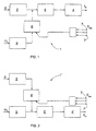
- Figure 1 illustrates a sound attenuation element 1.
- the sound attenuation element 1 comprises a detector 2 for the sound pressure p.
- the sound attenuation element 1 further comprises a detector 3 for the particle velocity.
- the device is used for indicating the normal component u x of particle velocity.
- the sound pressure detector 2 controls a dipole actuator 4 directly via a filter 5 on the basis of the measurement result of the sound pressure p.
- the dipole actuator 4 is used for producing a sound opposite to the original sound field.
- the intensity of the sound produced by the dipole actuator 4 is described with the strength f s of the dipole.
- the normal component u x of particle velocity measured with the particle velocity detector 3 is also utilized in controlling the dipole actuator 4.
- the effect of the particle velocity is taken into account by the device 6 producing a correction signal.
- the velocity component is multiplied by the approximation of the impedance H z of the sound field.
- H z ⁇ x c can be considered the initial value, where ⁇ is the density of the medium and c is the sound velocity in the medium.
- the approximation of the impedance H z is adjusted by measuring the remaining sound pressure, i.e. the residual sound pressure p res , which is sent to the device 6 producing a correction signal.
- control can be implemented with substantially no delay, and furthermore, by utilizing the velocity signal u x adjusted with the approximation of the impedance H z , an accurate result can be achieved.
- There may be several measuring devices for the residual sound pressure p res whereby the residual sound pressure p res can be measured in several places. If the environmental conditions and sound source remain constant, it is not necessary to alter the approximation of the impedance after the desired level of attenuation has been achieved.
- the measuring devices 7 for residual pressure can be used continuously, whereby the approximation of the impedance H 2 can be adjusted continuously by means of the devices, and thus the attenuation sound produced by the dipole actuator 4 can also be adjusted very accurately.
- FIG. 2 illustrates a second sound attenuation element 1'.
- the same numbers have the same significance as in Figure 1.
- a monopole actuator 4' is controlled via a filter 5' on the basis of the particle velocity. The intensity of the sound produced by the monopole actuator 4' is described with the volume velocity q s .
- the monopole actuator 4' is controlled by means of the sound pressure p in such a manner that the measurement result of the sound pressure p is adjusted with the approximation of the admittance H 1/z of the sound field.
- the admittance of the sound field is the inverse of the impedance of the sound field.
- the admittance function H 1/z of the sound field is adjusted in the same way as the impedance function H z of the sound field.
- Figure 3 illustrates a third sound attenuation element 1" according to the invention.
- the same numbers have the same significance as in Figures 1 and 2.
- the dipole actuator 4 is controlled directly on the basis of the sound pressure p.
- the particle velocity u x is not measured at all.
- the monopole actuator 4' is controlled with the measuring result of the sound pressure p, adjusted in the device producing a correction signal by means of the approximation of the admittance H 1/z of the sound field as in the case shown in Figure 2.
- Figure 4 illustrates a fourth sound attenuation element 1"' according to the invention.
- the monopole actuator 4' is controlled on the basis of the value of the particle velocity u x .
- the sound pressure p is not measured at all, but the dipole actuator 4 is controlled by means of the measuring result of the particle velocity u x , adjusted in the device 6 producing a correction signal by means of the approximation of the impedance H z as was explained in connection with Figure 1.
- FIG 5 illustrates an overall system of sound attenuation.
- the overall system comprises several sound attenuation elements 1, 1', 1" or 1"' of the invention. All measuring results achieved with the measuring device 7 for residual sound pressure are collected in the system in order to influence the adjustment of each attenuation element. The adjustment of different elements may depend differently on different residual sound pressures.
- the measuring devices 7 for residual sound pressure may be mobile and even portable, whereby the minimization of the sound pressure focuses most effectively on the persons carrying the device.
- the arrangement is suitable for mediums in which sound causes a longitudinal wave motion, i.e. besides air, the medium may be e.g. another gas or a liquid.
Landscapes
- Physics & Mathematics (AREA)
- Engineering & Computer Science (AREA)
- Acoustics & Sound (AREA)
- Multimedia (AREA)
- Measurement Of Mechanical Vibrations Or Ultrasonic Waves (AREA)
- Soundproofing, Sound Blocking, And Sound Damping (AREA)
- Devices For Supply Of Signal Current (AREA)
- Diaphragms For Electromechanical Transducers (AREA)
Abstract
Description
Claims (14)
- A method of attenuating sound, comprising measuring at least one component of a sound field, and producing attenuation sound by means of at least one actuator, and adjusting the measurement result with a coefficient, characterized in that the measurement result is adjusted with the approximation of the impedance or admittance of the sound field, and the approximation is adjusted on the basis of the measured residual sound pressure (pres).
- A method as claimed in claim 1, characterized in that the pressure (p) and particle velocity (ux) of the sound field are measured, and a dipole actuator (4) is controlled substantially directly by means of the sound pressure (p), and the influence of the particle velocity (ux) on the dipole actuator (4) is taken into account, adjusted with the approximation of the impedance of the sound field.
- A method as claimed in claim 1, characterized in that the particle velocity (ux) and sound pressure (p) of the sound field are measured, and a monopole actuator (4') is controlled substantially directly by means of the particle velocity (ux), and the influence of the sound pressure (p) on the monopole actuator (4') is taken into account, adjusted with the approximation of the admittance of the sound field.
- A method as claimed in claim 1, characterized in that the sound pressure (p) of the sound field is measured, and a dipole actuator (4) is controlled substantially directly by means of the sound pressure (p), and a monopole actuator (4') is controlled by means of the sound pressure (p) adjusted with the approximation of the admittance of the sound field.
- A method as claimed in claim 1, characterized in that the particle velocity (ux) of the sound field is measured, and a monopole actuator (4') is controlled substantially directly by means of the particle velocity (ux), and a dipole actuator (4) is controlled with the value of the particle velocity (ux), which has been adjusted by means of the approximation of the impedance of the sound field.
- A method as claimed in any one of the preceding claims, characterized in that the residual sound pressure (pres) is measured substantially continuously.
- A method as claimed in any one of the preceding claims, characterized in that the residual sound pressure (pres) is measured in several different places.
- An apparatus for attenuating sound, comprising at least one device measuring a component of a sound field and at least one actuator producing attenuation sound on the basis of the measurement result, characterized in that the apparatus comprises at least one device (7) measuring residual sound pressure and a device (6) producing a correction signal, and the device (6) is arranged to adjust the attenuation sound to be produced by means of the approximation of the impedance or admittance of the sound field, which is adjusted on the basis of the measured residual sound pressure (pres).
- An apparatus as claimed in claim 8, characterized in that the apparatus comprises a sound pressure detector (2), particle velocity detector (3), and dipole actuator (4) producing attenuation sound, whereby the sound pressure detector (2) is arranged to control the dipole actuator (4) substantially directly, and the particle velocity detector (3) is arranged to control the dipole actuator (4) via the device (6) producing a correction signal, and the device (6) is arranged to produce the correction signal by means of the approximation of the impedance of the sound field.
- An apparatus as claimed in claim 8, characterized in that the apparatus comprises a sound pressure detector (2), particle velocity detector (3), and monopole actuator (4') arranged to produce attenuation sound, whereby the particle velocity detector (3) is arranged to control the monopole actuator (4') substantially directly, and the sound pressure detector (2) is arranged to control the monopole actuator (4') via the device (6) producing a correction signal, and the device (6) is arranged to produce the correction signal by means of the approximation of the admittance of the sound field.
- An apparatus as claimed in claim 8, characterized in that the apparatus comprises a sound pressure detector (2), and a dipole actuator (4) and monopole actuator (4') producing attenuation sound, whereby the sound pressure detector (2) is arranged to control the dipole actuator (4) substantially directly and the monopole actuator (4') via the device (6) producing a correction signal, and the device (6) is arranged to produce the correction signal by means of the approximation of the admittance of the sound field.
- An apparatus as claimed in claim 8, characterized in that the apparatus comprises a particle velocity detector (3), and a dipole actuator (4) and monopole actuator (4') producing attenuation sound, whereby the particle velocity detector (3) is arranged to control the monopole actuator (4') substantially directly and the dipole actuator (4) via the device (6) producing a correction signal, and the device (6) is arranged to produce the correction signal by means of the approximation of the impedance of the sound field.
- An apparatus as claimed in any one of claims 8 to 12, characterized in that the apparatus comprises several devices (7) for measuring residual sound pressure (pres).
- An apparatus as claimed in any one of claims 8 to 13, characterized in that at least one device (7) for measuring residual sound pressure (pres) is arranged to be carried by a person in the sound field.
Applications Claiming Priority (3)
| Application Number | Priority Date | Filing Date | Title |
|---|---|---|---|
| FI964636A FI105602B (en) | 1996-11-20 | 1996-11-20 | Method and device for sound attenuation |
| FI964636 | 1996-11-20 | ||
| PCT/FI1997/000707 WO1998022933A1 (en) | 1996-11-20 | 1997-11-19 | Method and apparatus for attenuating sound |
Publications (2)
| Publication Number | Publication Date |
|---|---|
| EP1002311A1 EP1002311A1 (en) | 2000-05-24 |
| EP1002311B1 true EP1002311B1 (en) | 2002-03-06 |
Family
ID=8547098
Family Applications (1)
| Application Number | Title | Priority Date | Filing Date |
|---|---|---|---|
| EP97913207A Expired - Lifetime EP1002311B1 (en) | 1996-11-20 | 1997-11-19 | Method and apparatus for attenuating sound |
Country Status (6)
| Country | Link |
|---|---|
| EP (1) | EP1002311B1 (en) |
| AT (1) | ATE214191T1 (en) |
| AU (1) | AU5054498A (en) |
| DE (1) | DE69710928T2 (en) |
| FI (1) | FI105602B (en) |
| WO (1) | WO1998022933A1 (en) |
Families Citing this family (1)
| Publication number | Priority date | Publication date | Assignee | Title |
|---|---|---|---|---|
| GB2542860B (en) * | 2015-10-04 | 2021-10-20 | Labxero Ltd | Acoustic processing device |
Family Cites Families (3)
| Publication number | Priority date | Publication date | Assignee | Title |
|---|---|---|---|---|
| US4473906A (en) * | 1980-12-05 | 1984-09-25 | Lord Corporation | Active acoustic attenuator |
| GB8328997D0 (en) * | 1983-10-31 | 1983-11-30 | Secr Defence | Active noise reduction |
| JPH05223334A (en) * | 1992-02-14 | 1993-08-31 | Matsushita Seiko Co Ltd | Active silencer |
-
1996
- 1996-11-20 FI FI964636A patent/FI105602B/en not_active IP Right Cessation
-
1997
- 1997-11-19 AU AU50544/98A patent/AU5054498A/en not_active Abandoned
- 1997-11-19 DE DE69710928T patent/DE69710928T2/en not_active Expired - Fee Related
- 1997-11-19 AT AT97913207T patent/ATE214191T1/en not_active IP Right Cessation
- 1997-11-19 EP EP97913207A patent/EP1002311B1/en not_active Expired - Lifetime
- 1997-11-19 WO PCT/FI1997/000707 patent/WO1998022933A1/en not_active Ceased
Also Published As
| Publication number | Publication date |
|---|---|
| ATE214191T1 (en) | 2002-03-15 |
| DE69710928D1 (en) | 2002-04-11 |
| AU5054498A (en) | 1998-06-10 |
| FI964636L (en) | 1998-05-21 |
| FI964636A0 (en) | 1996-11-20 |
| DE69710928T2 (en) | 2002-09-19 |
| WO1998022933A1 (en) | 1998-05-28 |
| EP1002311A1 (en) | 2000-05-24 |
| FI105602B (en) | 2000-09-15 |
Similar Documents
| Publication | Publication Date | Title |
|---|---|---|
| US4783817A (en) | Electronic noise attenuation system | |
| US5436556A (en) | Signal detector and method for detecting signals having selected frequency characteristics | |
| EP0527556A1 (en) | Adjustable filter for differential microphones | |
| CA1125431A (en) | Time varying gain amplifier for side scan sonar applications | |
| CA2304616A1 (en) | Method of and apparatus for nonobtrusively obtaining on-line measurements of a process control device parameter | |
| US3844175A (en) | Noise source level detection | |
| US4453238A (en) | Apparatus and method for determining the phase sensitivity of hydrophones | |
| Da Silva et al. | Design and construction of a low cost impedance tube for sound absorption coefficients measurements | |
| EP1002311A1 (en) | Method and apparatus for attenuating sound | |
| RU2042123C1 (en) | Multiprofile acoustic leak detector and process of its tuning | |
| US6996030B2 (en) | Apparatus and method for minimizing reception nulls in heterodyned ultrasonic signals | |
| JPH0650258B2 (en) | Sound calibration device | |
| EP0665671A3 (en) | Apparatus and method for echo attenuation | |
| Sakurai et al. | A computational software for noise measurement and toward its identification | |
| Savell | Precision and accuracy of jet noise measurements | |
| Polychronopoulos et al. | Efficient filter-based model for resonator panel absorbers | |
| Frederiksen et al. | Measurement of Microphone Free-field Corrections and Determination of their Uncertainties | |
| Nordby et al. | Measurement of sound intensity by use of a dual channel real-time analyser and a special sound intensity microphone | |
| Royster et al. | Sound measurement: instrumentation and noise | |
| US4223400A (en) | Low-frequency directional hydrophone | |
| Kuehn | Noise measurement | |
| GB1558641A (en) | Acoustic measuring system | |
| Wang | Vehicle noise measurement and analysis | |
| US3292139A (en) | Sonar performance computer | |
| Bernstein | Sound and Noise Level Measurements |
Legal Events
| Date | Code | Title | Description |
|---|---|---|---|
| PUAI | Public reference made under article 153(3) epc to a published international application that has entered the european phase |
Free format text: ORIGINAL CODE: 0009012 |
|
| 17P | Request for examination filed |
Effective date: 19990528 |
|
| AK | Designated contracting states |
Kind code of ref document: A1 Designated state(s): AT BE CH DE DK ES FI FR GB GR IE IT LI LU MC NL PT SE |
|
| GRAG | Despatch of communication of intention to grant |
Free format text: ORIGINAL CODE: EPIDOS AGRA |
|
| 17Q | First examination report despatched |
Effective date: 20010426 |
|
| GRAG | Despatch of communication of intention to grant |
Free format text: ORIGINAL CODE: EPIDOS AGRA |
|
| GRAH | Despatch of communication of intention to grant a patent |
Free format text: ORIGINAL CODE: EPIDOS IGRA |
|
| GRAH | Despatch of communication of intention to grant a patent |
Free format text: ORIGINAL CODE: EPIDOS IGRA |
|
| REG | Reference to a national code |
Ref country code: GB Ref legal event code: IF02 |
|
| GRAA | (expected) grant |
Free format text: ORIGINAL CODE: 0009210 |
|
| AK | Designated contracting states |
Kind code of ref document: B1 Designated state(s): AT BE CH DE DK ES FI FR GB GR IE IT LI LU MC NL PT SE |
|
| PG25 | Lapsed in a contracting state [announced via postgrant information from national office to epo] |
Ref country code: NL Free format text: LAPSE BECAUSE OF FAILURE TO SUBMIT A TRANSLATION OF THE DESCRIPTION OR TO PAY THE FEE WITHIN THE PRESCRIBED TIME-LIMIT Effective date: 20020306 Ref country code: LI Free format text: LAPSE BECAUSE OF FAILURE TO SUBMIT A TRANSLATION OF THE DESCRIPTION OR TO PAY THE FEE WITHIN THE PRESCRIBED TIME-LIMIT Effective date: 20020306 Ref country code: GR Free format text: LAPSE BECAUSE OF FAILURE TO SUBMIT A TRANSLATION OF THE DESCRIPTION OR TO PAY THE FEE WITHIN THE PRESCRIBED TIME-LIMIT Effective date: 20020306 Ref country code: FI Free format text: LAPSE BECAUSE OF FAILURE TO SUBMIT A TRANSLATION OF THE DESCRIPTION OR TO PAY THE FEE WITHIN THE PRESCRIBED TIME-LIMIT Effective date: 20020306 Ref country code: CH Free format text: LAPSE BECAUSE OF FAILURE TO SUBMIT A TRANSLATION OF THE DESCRIPTION OR TO PAY THE FEE WITHIN THE PRESCRIBED TIME-LIMIT Effective date: 20020306 Ref country code: BE Free format text: LAPSE BECAUSE OF FAILURE TO SUBMIT A TRANSLATION OF THE DESCRIPTION OR TO PAY THE FEE WITHIN THE PRESCRIBED TIME-LIMIT Effective date: 20020306 Ref country code: AT Free format text: LAPSE BECAUSE OF FAILURE TO SUBMIT A TRANSLATION OF THE DESCRIPTION OR TO PAY THE FEE WITHIN THE PRESCRIBED TIME-LIMIT Effective date: 20020306 |
|
| REF | Corresponds to: |
Ref document number: 214191 Country of ref document: AT Date of ref document: 20020315 Kind code of ref document: T |
|
| REG | Reference to a national code |
Ref country code: CH Ref legal event code: EP |
|
| REF | Corresponds to: |
Ref document number: 69710928 Country of ref document: DE Date of ref document: 20020411 |
|
| PG25 | Lapsed in a contracting state [announced via postgrant information from national office to epo] |
Ref country code: SE Free format text: LAPSE BECAUSE OF FAILURE TO SUBMIT A TRANSLATION OF THE DESCRIPTION OR TO PAY THE FEE WITHIN THE PRESCRIBED TIME-LIMIT Effective date: 20020606 Ref country code: PT Free format text: LAPSE BECAUSE OF FAILURE TO SUBMIT A TRANSLATION OF THE DESCRIPTION OR TO PAY THE FEE WITHIN THE PRESCRIBED TIME-LIMIT Effective date: 20020606 Ref country code: DK Free format text: LAPSE BECAUSE OF FAILURE TO SUBMIT A TRANSLATION OF THE DESCRIPTION OR TO PAY THE FEE WITHIN THE PRESCRIBED TIME-LIMIT Effective date: 20020606 |
|
| ET | Fr: translation filed | ||
| NLV1 | Nl: lapsed or annulled due to failure to fulfill the requirements of art. 29p and 29m of the patents act | ||
| REG | Reference to a national code |
Ref country code: CH Ref legal event code: PL |
|
| PG25 | Lapsed in a contracting state [announced via postgrant information from national office to epo] |
Ref country code: ES Free format text: LAPSE BECAUSE OF FAILURE TO SUBMIT A TRANSLATION OF THE DESCRIPTION OR TO PAY THE FEE WITHIN THE PRESCRIBED TIME-LIMIT Effective date: 20020925 |
|
| PG25 | Lapsed in a contracting state [announced via postgrant information from national office to epo] |
Ref country code: LU Free format text: LAPSE BECAUSE OF NON-PAYMENT OF DUE FEES Effective date: 20021119 Ref country code: IE Free format text: LAPSE BECAUSE OF NON-PAYMENT OF DUE FEES Effective date: 20021119 |
|
| PLBE | No opposition filed within time limit |
Free format text: ORIGINAL CODE: 0009261 |
|
| STAA | Information on the status of an ep patent application or granted ep patent |
Free format text: STATUS: NO OPPOSITION FILED WITHIN TIME LIMIT |
|
| 26N | No opposition filed |
Effective date: 20021209 |
|
| PG25 | Lapsed in a contracting state [announced via postgrant information from national office to epo] |
Ref country code: MC Free format text: LAPSE BECAUSE OF NON-PAYMENT OF DUE FEES Effective date: 20030601 |
|
| REG | Reference to a national code |
Ref country code: IE Ref legal event code: MM4A |
|
| PGFP | Annual fee paid to national office [announced via postgrant information from national office to epo] |
Ref country code: FR Payment date: 20041010 Year of fee payment: 8 |
|
| PGFP | Annual fee paid to national office [announced via postgrant information from national office to epo] |
Ref country code: GB Payment date: 20041014 Year of fee payment: 8 |
|
| PGFP | Annual fee paid to national office [announced via postgrant information from national office to epo] |
Ref country code: DE Payment date: 20041020 Year of fee payment: 8 |
|
| PG25 | Lapsed in a contracting state [announced via postgrant information from national office to epo] |
Ref country code: IT Free format text: LAPSE BECAUSE OF NON-PAYMENT OF DUE FEES Effective date: 20051119 Ref country code: GB Free format text: LAPSE BECAUSE OF NON-PAYMENT OF DUE FEES Effective date: 20051119 |
|
| PG25 | Lapsed in a contracting state [announced via postgrant information from national office to epo] |
Ref country code: DE Free format text: LAPSE BECAUSE OF NON-PAYMENT OF DUE FEES Effective date: 20060601 |
|
| GBPC | Gb: european patent ceased through non-payment of renewal fee |
Effective date: 20051119 |
|
| PG25 | Lapsed in a contracting state [announced via postgrant information from national office to epo] |
Ref country code: FR Free format text: LAPSE BECAUSE OF NON-PAYMENT OF DUE FEES Effective date: 20060731 |
|
| REG | Reference to a national code |
Ref country code: FR Ref legal event code: ST Effective date: 20060731 |