EP1000419B1 - Security element for the electronic surveillance of articles - Google Patents
Security element for the electronic surveillance of articles Download PDFInfo
- Publication number
- EP1000419B1 EP1000419B1 EP98943767A EP98943767A EP1000419B1 EP 1000419 B1 EP1000419 B1 EP 1000419B1 EP 98943767 A EP98943767 A EP 98943767A EP 98943767 A EP98943767 A EP 98943767A EP 1000419 B1 EP1000419 B1 EP 1000419B1
- Authority
- EP
- European Patent Office
- Prior art keywords
- security element
- materials
- surveillance system
- characteristic signal
- signal
- Prior art date
- Legal status (The legal status is an assumption and is not a legal conclusion. Google has not performed a legal analysis and makes no representation as to the accuracy of the status listed.)
- Expired - Lifetime
Links
Images



Classifications
-
- G—PHYSICS
- G08—SIGNALLING
- G08B—SIGNALLING SYSTEMS, e.g. PERSONAL CALLING SYSTEMS; ORDER TELEGRAPHS; ALARM SYSTEMS
- G08B13/00—Burglar, theft or intruder alarms
- G08B13/22—Electrical actuation
- G08B13/24—Electrical actuation by interference with electromagnetic field distribution
- G08B13/2402—Electronic Article Surveillance [EAS], i.e. systems using tags for detecting removal of a tagged item from a secure area, e.g. tags for detecting shoplifting
- G08B13/2405—Electronic Article Surveillance [EAS], i.e. systems using tags for detecting removal of a tagged item from a secure area, e.g. tags for detecting shoplifting characterised by the tag technology used
- G08B13/2408—Electronic Article Surveillance [EAS], i.e. systems using tags for detecting removal of a tagged item from a secure area, e.g. tags for detecting shoplifting characterised by the tag technology used using ferromagnetic tags
-
- G—PHYSICS
- G01—MEASURING; TESTING
- G01V—GEOPHYSICS; GRAVITATIONAL MEASUREMENTS; DETECTING MASSES OR OBJECTS; TAGS
- G01V15/00—Tags attached to, or associated with, an object, in order to enable detection of the object
-
- G—PHYSICS
- G08—SIGNALLING
- G08B—SIGNALLING SYSTEMS, e.g. PERSONAL CALLING SYSTEMS; ORDER TELEGRAPHS; ALARM SYSTEMS
- G08B13/00—Burglar, theft or intruder alarms
- G08B13/22—Electrical actuation
- G08B13/24—Electrical actuation by interference with electromagnetic field distribution
- G08B13/2402—Electronic Article Surveillance [EAS], i.e. systems using tags for detecting removal of a tagged item from a secure area, e.g. tags for detecting shoplifting
- G08B13/2405—Electronic Article Surveillance [EAS], i.e. systems using tags for detecting removal of a tagged item from a secure area, e.g. tags for detecting shoplifting characterised by the tag technology used
- G08B13/2414—Electronic Article Surveillance [EAS], i.e. systems using tags for detecting removal of a tagged item from a secure area, e.g. tags for detecting shoplifting characterised by the tag technology used using inductive tags
- G08B13/2417—Electronic Article Surveillance [EAS], i.e. systems using tags for detecting removal of a tagged item from a secure area, e.g. tags for detecting shoplifting characterised by the tag technology used using inductive tags having a radio frequency identification chip
-
- G—PHYSICS
- G08—SIGNALLING
- G08B—SIGNALLING SYSTEMS, e.g. PERSONAL CALLING SYSTEMS; ORDER TELEGRAPHS; ALARM SYSTEMS
- G08B13/00—Burglar, theft or intruder alarms
- G08B13/22—Electrical actuation
- G08B13/24—Electrical actuation by interference with electromagnetic field distribution
- G08B13/2402—Electronic Article Surveillance [EAS], i.e. systems using tags for detecting removal of a tagged item from a secure area, e.g. tags for detecting shoplifting
- G08B13/2428—Tag details
- G08B13/2437—Tag layered structure, processes for making layered tags
-
- G—PHYSICS
- G08—SIGNALLING
- G08B—SIGNALLING SYSTEMS, e.g. PERSONAL CALLING SYSTEMS; ORDER TELEGRAPHS; ALARM SYSTEMS
- G08B13/00—Burglar, theft or intruder alarms
- G08B13/22—Electrical actuation
- G08B13/24—Electrical actuation by interference with electromagnetic field distribution
- G08B13/2402—Electronic Article Surveillance [EAS], i.e. systems using tags for detecting removal of a tagged item from a secure area, e.g. tags for detecting shoplifting
- G08B13/2428—Tag details
- G08B13/2437—Tag layered structure, processes for making layered tags
- G08B13/2442—Tag materials and material properties thereof, e.g. magnetic material details
Definitions
- This invention relates to a security element for the electronic surveillance of articles.
- harmonic detection system As an alternative solution of a system referred to as a harmonic detection system, it has further become known to use only one interrogation field in the kilohertz range for excitation of the security element, with the characteristic signal of the security element occurring again at the clock rate of a low-frequency field cycling the soft magnetic material between the two states of saturation.
- the shape of the characteristic signal is subsequently compared with a predetermined signal shape. If the two coincide, this is interpreted as the unauthorized presence of a protected article in the interrogation zone; an alarm is then produced indicating to sales staff that a theft has occurred.
- the hysteresis loops of security elements manufactured from a soft magnetic material follow an essentially linear course between the two states of saturation.
- security elements have become known whose hysteresis loops exhibit an abrupt transition between the two saturation states as soon as an external magnetic field compels them to change their saturation direction.
- Materials showing discontinuities between the two states of saturation are referred to as "materials with Barkhausen effect”. They are characterized by high permeability already in the low-frequency range, which means that they are excited to emit a characteristic signal by low-frequency interrogation fields. Further, the characteristic signals of Barkhausen materials feature a sharp peak. This again means that a relatively large signal component occurs in high-order harmonics.
- Materials of this type are manufactured by subjecting soft magnetic materials to a suitable annealing process.
- the properties of these materials and the physical principles of the Barkhausen effect are described in detail in U.S. Pat. No. 4,660,025 or also in EP 0 448 114 A1.
- these prior-art specifications make reference to how soft magnetic material can be subjected to special physical treatment to turn into a material with high Barkhausen effect.
- Security elements utilizing the Barkhausen effect differ significantly from soft magnetic security elements as regards their signal shape. As a direct consequence thereof, the probability of their being detected in so-called harmonic systems is relatively low; soft magnetic security elements, in turn, are difficult to detect in systems designed for the detection of security elements utilizing the Barkhausen effect. The situation is different if it is aimed to have a security element detected in both a harmonic and a Barkhausen surveillance system. Where both types of security element, that is one employing soft magnetic and one employing Barkhausen material, are combined for integration into one security element, these may, under circumstances, influence each other through their magnetic fields such that the intermodulation signal of the combined security element is detectable neither in a harmonic nor in a Barkhausen surveillance system.
- US 5,565,847 describes a tag which has a plurality of resonating sections each having separate frequencies of excitation. Each of the strips has the same material in different lengths in order to achieve different oscillating frequencies. This is to provide a multi-bit tag.
- an anti-pilferage tag which uses different ferromagnetic material compositions and in particular a combination of hard or semi-hard magnetic material which a soft magnetic material.
- the hard or semi-hard magnetic material acts as a clamp which holds the soft material in a fixed magnetic state to give rise to a specific response to an interrogating field.
- the security element is comprised of at least two materials of high permeability which, when excited by an external alternating magnetic field, emit each a characteristic signal; the maximum signal components of the two materials lie in different frequency ranges; further, the signal components of the one material are negligibly low in that particular frequency range in which the signal component of the other material is at a maximum level.
- the physical properties of the two materials are coordinated such that the component of the characteristic signal of the one material is negligibly low in that particular frequency range in which the signal component of the characteristic signal of the other material is at a maximum level.
- the security element to be comprised of a material with Barkhausen effect (high permeability; low coercive force in the frequency range (F1), high coercive force in the frequency range (F2), where F2 >> F1), which material is excited by an external magnetic field to emit a characteristic signal detectable in a surveillance system (S1), and of a soft magnetic material (high permeability; low coercive force in the frequency range (F2)) which, when an alternating magnetic field is applied, is excited to emit a characteristic signal detectable in a surveillance system (S2); further, the physical properties of the two materials are coordinated such that the intensity of the characteristic signal (signal 2) of the soft magnetic material is negligibly low in the detection range (F1) of the surveillance system (S1), whilst it attains its maximum level in the detection range (F2) of the surveillance system (S2), and that the intensity of the characteristic signal (signal 1) of the material with Barkhausen effect attains a maximum level in the detection range
- Barkhausen security elements Physical properties in respect of the Barkhausen security elements are understood to mean that the material is optimized by its outer shape, by annealing, or by inducing mechanical stress.
- variation of the physical properties for example, in cases where strip elements are used, means an adjustment of the length and thus of the demagnetizing factor of the strip elements.
- the two materials are present in the form of a thin film and/or a strip and/or a wire and/or a foil. Conveniently, the two materials are utilized in like shape.
- optimization of the frequency response of the materials utilized is effected by a variation of their physical properties.
- a still further optimization may be accomplished by a suitable relative arrangement of the materials.
- this relative arrangement is selected such that coupling via their magnetic fields is as low as possible.
- the simplest procedure would be to select the relative distance of the Barkhausen security element and the soft magnetic security element correspondingly large. This, however, entails the disadvantage that it is necessary for the combined security element to be of large dimensions, which one wishes to avoid generally (for cost reasons). Optimization within the meaning of the invention rather means seeking a compromise between minimum interaction and maximum possible detection rate in systems designed to operate in different frequency ranges for the detection of characteristic signals.
- the materials with an elongated shape and aligning them parallel to each other. This enables the manufacture of security elements having relatively little lateral extent.
- the size of the security elements plays a secondary role, it is possible in cases where two materials are used to arrange them at any desired relative angle ( ⁇ ). In an optimum arrangement, the two materials are at right angles to each other, because then mutual interference equals zero.
- the security element offers the possibility for deactivation. This is achieved by adding a semi-hard or hard magnetic material, preferable in the form of laminas, to at least one of the two materials. Deactivation is then achieved by magnetizing the semi hard or hard magnetic material to a level high enough to prevent the soft magnetic material and/or the material with the strong Barkhausen effect from generating a characteristic a signal within the interrogation field.
- the soft magnetic component If only one of the two materials is made deactivatable, for instance the soft magnetic component, optimum detection could be achieved in the other type of surveillance systems, in this case the Barkhausen system, and vice versa. If both materials are combined with a semi hard or hard magnetic component the security element could be deactivated for either type of surveillance system.
- the semi-hard or hard magnetic components differ in at least one of their magnetic properties, for instance their coercive field levels. This allows to chose between optimum detection in either system on one hand and optimum compatibility on the other
- FIG. 1a of the drawings there is shown a perspective representation of a surveillance system S1 for Barkhausen security elements, while FIG. 1b shows a perspective representation of a harmonic surveillance system S2.
- Both surveillance systems bear great resemblance to each other as regards their structure and their mode of operation in general. The differences lie merely in the detail.
- the transmitting device 4 emits an interrogation field H into the zone 6 to be protected.
- the Barkhausen security element 1 and the soft magnetic security element 2 are excited by the interrogation field H to emit a characteristic signal.
- the interrogation frequency of the Barkhausen surveillance system S1 is in the low-frequency range (at 70 hertz, for example)
- the interrogation frequency of the harmonic system S2 lies in the kilohertz range.
- the high-frequency interrogation frequency in harmonic surveillance systems may also be modulated by a low-frequency interrogation frequency.
- the characteristic signal is detected by the associated receiving device 5 and transmitted to the computing/control unit 7.
- This unit evaluates the signal in accordance with a predetermined algorithm, releasing, where applicable, an alarm to indicate the unauthorized presence of a protected article 10 in the interrogation zone 6.
- FIG. 2 the static hysteresis loops of a soft magnetic material 2 and of a material 1 with high Barkhausen effect are plotted in the conventional H-M diagram. While the hysteresis loop of the soft magnetic material 2 exhibits linear continuities between the two opposite states of magnetization, the material 1 with the high Barkhausen effect shows discontinuities at a relatively low field strength H.
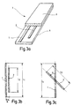
- FIG. 3a shows an advantageous design of the security element 3 of the present invention.
- Two strip members are arranged on a substratum 8. While the one strip member is made of a material 1 with high Barkhausen effect, the other is fabricated from a soft magnetic material 2.
- the two strip members 1, 2 are arranged parallel to each other. They are covered by a layer 9 suitable for being printed upon.
- FIG. 3b shows the two strip members 1, 2 without the substratum 8 and without the print layer 9.
- the physical properties of the two strip members 1, 2 are dimensioned such that the characteristic signals of the two security elements 1, 2 are varied only insignificantly by the effect of the other security element 2, 1, respectively. Therefore, the security element 3 of the invention is detected equally reliably by both surveillance systems S1, S2.
- FIG. 3c shows an alternative design of the security element 3 of the present invention.
- the two strip members 1, 2 intersect at an angle ⁇ .
- this angle ⁇ amounts to 90 degrees; in such an arrangement, mutual interference of the magnetic fields of the two security elements 1, 2 is zero. This is, however, at the expense of a correspondingly large dimension of the security element 3 which does not appear acceptable for any application.
- FIG. 3d shows a deactivatable version of the security element 3 of the present invention.
- the Barkhausen material 1 and the soft magnetic material 2 are combined with a semi-hard and/or hard magnetic material 11; 12.
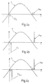
- FIGS. 4, 5 and 6 illustrate clearly by way of time charts the effect achieved by the security element 3 of the present invention in the different surveillance systems S1, S2.
- FIG. 4 relates to the signals produced by a soft magnetic security element 2 (FIG. 4a), a Barkhausen security element 1 (FIG. 4b), and the security element of the invention (FIG. 4c) in a Barkhausen surveillance system S1.
- the sinusoidal curve in the FIGURES indicates the interrogation frequency of the interrogation field H which, in the event of a Barkhausen surveillance system S1, lies in the low-frequency range, for example, at 70 hertz.
- the security element 1, 2, 3 emits a characteristic signal inducing a voltage U ind in the receiving device 5.
- the computing/control unit 7 identifies a received signal as a characteristic signal, producing an alarm.
- FIG. 4a shows, the signal component produced by a soft magnetic material 2 in a Barkhausen surveillance system S1 is relatively small, whilst the Barkhausen security element 1 in the Barkhausen surveillance system S1 generates a sharp peak. If there were mutual interference of the two security elements 1, 2 in an uncontrolled way, the resultant intermodulation signal would materially differ from the typical peak shape which stems from a Barkhausen security element 1 operating without disturbance. In consequence, the risk increases for the Barkhausen surveillance system S1 to be unable to identify a "simple" combination of Barkhausen security element 1 and soft magnetic security element 2 as a security element per se, accordingly failing to activate an alarm. Attendant upon this is a material reduction of the detection probability.
- the characteristic signal of the security element 3 of the invention differs only insignificantly from the characteristic signal of a conventional Barkhausen security element 1.
- the computing/control unit 7 of the Barkhausen surveillance system S1 will readily identify the characteristic signal of the security element 3 of the invention, consequently producing an alarm.
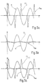
- FIG. 5 shows the analogous relationships in cases where a harmonic surveillance system S2 is utilized.
- the sinusoidal curve indicates again the interrogation frequency of the interrogation field H.
- this frequency is in the kilohertz range, for example, at 5 kilohertz.
- a soft magnetic security element 2 generates in the harmonic system S2 a distinctive signal which is again measured as an induced voltage U ind in the receiving device 5.
- the signal of the Barkhausen security element 1 adversely affects the detection rate of the harmonic surveillance system S2 for the reasons recited in connection with the Barkhausen surveillance system 1.
- FIGS. 5a and 5c reveals that the shape of the characteristic signal of the security element 3 of the invention differs little from the shape of the characteristic signal of a simple soft magnetic security element 2.
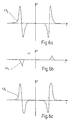
- FIG. 6 illustrates the characteristic signals of a soft magnetic security element 2 (FIG. 6a), a Barkhausen security element 1 (FIG. 6b), and the security element 3 of the invention (FIG. 6c) in a harmonic surveillance system S2 having two high-frequency interrogation fields f1, f2 and one low-frequency interrogation field f3.
- a corresponding harmonic surveillance system S2 has been presented in the opening statement hereof.
- FIGS. 6a and 6c reveals that the characteristic signals of the soft magnetic security element 2 and the security element 3 of the invention essentially coincide.
- the signal shape of the Barkhausen security element 1 (FIG. 6b) differs from the expected shape.
- the requisite high detection rate of the surveillance system is not reduced either in the use of the security element 3 of the invention.
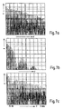
- FIGS. 7a through 7c reflect the situation as it presents itself when the security element 3 of the invention is utilized in a Barkhausen surveillance system S1. However, instead of showing signal waveforms, these Figures show the signal frequency spectra.
- FIG. 7b shows the frequency spectrum of a soft magnetic security element 2 in a Barkhausen surveillance system S1.
Landscapes
- Physics & Mathematics (AREA)
- General Physics & Mathematics (AREA)
- Engineering & Computer Science (AREA)
- Automation & Control Theory (AREA)
- Computer Security & Cryptography (AREA)
- Electromagnetism (AREA)
- Life Sciences & Earth Sciences (AREA)
- General Life Sciences & Earth Sciences (AREA)
- Geophysics (AREA)
- Burglar Alarm Systems (AREA)
- Control Of Vending Devices And Auxiliary Devices For Vending Devices (AREA)
- Fixed Capacitors And Capacitor Manufacturing Machines (AREA)
Abstract
Description
- This invention relates to a security element for the electronic surveillance of articles.
- Security elements in the form of soft magnetic strip material are frequently used in department stores for the protection of merchandise against pilferage. To accomplish a sufficiently high detection rate, sophisticated methods are employed which reduce the risk of false alarms effectively. Thus, it is known from EP 123 586 B to emit into the interrogation zone, in addition to two interrogation fields with the frequencies f1 and f2 in the kilohertz range, a field with a frequency in the hertz range. The two interrogation fields with the frequencies f1 and f2 excite a security element present in the interrogation zone to remit a characteristic signal with the intermodulation frequencies n • f1 ± m • f2 (where n, m = 0, 1, 2,...). The low-frequency interrogation field has the effect of driving the security element from saturation in one direction into saturation in the other direction at the clock rate of this particular field. As a result, the characteristic signal occurs cyclically with the frequency of the low-frequency field.
- As an alternative solution of a system referred to as a harmonic detection system, it has further become known to use only one interrogation field in the kilohertz range for excitation of the security element, with the characteristic signal of the security element occurring again at the clock rate of a low-frequency field cycling the soft magnetic material between the two states of saturation.
- For purposes of evaluation, the shape of the characteristic signal is subsequently compared with a predetermined signal shape. If the two coincide, this is interpreted as the unauthorized presence of a protected article in the interrogation zone; an alarm is then produced indicating to sales staff that a theft has occurred.
- The hysteresis loops of security elements manufactured from a soft magnetic material follow an essentially linear course between the two states of saturation. In addition, security elements have become known whose hysteresis loops exhibit an abrupt transition between the two saturation states as soon as an external magnetic field compels them to change their saturation direction. Materials showing discontinuities between the two states of saturation are referred to as "materials with Barkhausen effect". They are characterized by high permeability already in the low-frequency range, which means that they are excited to emit a characteristic signal by low-frequency interrogation fields. Further, the characteristic signals of Barkhausen materials feature a sharp peak. This again means that a relatively large signal component occurs in high-order harmonics.
- Materials of this type are manufactured by subjecting soft magnetic materials to a suitable annealing process. The properties of these materials and the physical principles of the Barkhausen effect are described in detail in U.S. Pat. No. 4,660,025 or also in EP 0 448 114 A1. In particular, these prior-art specifications make reference to how soft magnetic material can be subjected to special physical treatment to turn into a material with high Barkhausen effect.
- Security elements utilizing the Barkhausen effect differ significantly from soft magnetic security elements as regards their signal shape. As a direct consequence thereof, the probability of their being detected in so-called harmonic systems is relatively low; soft magnetic security elements, in turn, are difficult to detect in systems designed for the detection of security elements utilizing the Barkhausen effect. The situation is different if it is aimed to have a security element detected in both a harmonic and a Barkhausen surveillance system. Where both types of security element, that is one employing soft magnetic and one employing Barkhausen material, are combined for integration into one security element, these may, under circumstances, influence each other through their magnetic fields such that the intermodulation signal of the combined security element is detectable neither in a harmonic nor in a Barkhausen surveillance system.
- US 5,565,847 describes a tag which has a plurality of resonating sections each having separate frequencies of excitation. Each of the strips has the same material in different lengths in order to achieve different oscillating frequencies. This is to provide a multi-bit tag.
- According to EP 0295085, an anti-pilferage tag is disclosed which uses different ferromagnetic material compositions and in particular a combination of hard or semi-hard magnetic material which a soft magnetic material. The hard or semi-hard magnetic material acts as a clamp which holds the soft material in a fixed magnetic state to give rise to a specific response to an interrogating field.
- It is an object of the present invention to propose a security element which is detected by surveillance systems operating in different frequency ranges.
- This object is accomplished in that the security element is comprised of at least two materials of high permeability which, when excited by an external alternating magnetic field, emit each a characteristic signal; the maximum signal components of the two materials lie in different frequency ranges; further, the signal components of the one material are negligibly low in that particular frequency range in which the signal component of the other material is at a maximum level.
- According to an advantageous further feature of the security element of the present invention, the physical properties of the two materials are coordinated such that the component of the characteristic signal of the one material is negligibly low in that particular frequency range in which the signal component of the characteristic signal of the other material is at a maximum level.
- Another solution aimed at accomplishing the object of the present invention provides for the security element to be comprised of a material with Barkhausen effect (high permeability; low coercive force in the frequency range (F1), high coercive force in the frequency range (F2), where F2 >> F1), which material is excited by an external magnetic field to emit a characteristic signal detectable in a surveillance system (S1), and of a soft magnetic material (high permeability; low coercive force in the frequency range (F2)) which, when an alternating magnetic field is applied, is excited to emit a characteristic signal detectable in a surveillance system (S2); further, the physical properties of the two materials are coordinated such that the intensity of the characteristic signal (signal 2) of the soft magnetic material is negligibly low in the detection range (F1) of the surveillance system (S1), whilst it attains its maximum level in the detection range (F2) of the surveillance system (S2), and that the intensity of the characteristic signal (signal 1) of the material with Barkhausen effect attains a maximum level in the detection range (F1) of the surveillance system (S1), whilst it is negligibly low in the detection range (F2) of the surveillance system (S2).
- Physical properties in respect of the Barkhausen security elements are understood to mean that the material is optimized by its outer shape, by annealing, or by inducing mechanical stress. In respect to the soft magnetic material, such variation of the physical properties, for example, in cases where strip elements are used, means an adjustment of the length and thus of the demagnetizing factor of the strip elements.
- In an advantageous feature of the security element of the invention, the two materials are present in the form of a thin film and/or a strip and/or a wire and/or a foil. Conveniently, the two materials are utilized in like shape.
- As mentioned in the foregoing, optimization of the frequency response of the materials utilized is effected by a variation of their physical properties. As a preferred further feature, it is generally proposed dimensioning the bulk components of the two materials such that their signal components in the respective other surveillance system are negligibly low.
- A still further optimization may be accomplished by a suitable relative arrangement of the materials. Preferably, this relative arrangement is selected such that coupling via their magnetic fields is as low as possible. The simplest procedure would be to select the relative distance of the Barkhausen security element and the soft magnetic security element correspondingly large. This, however, entails the disadvantage that it is necessary for the combined security element to be of large dimensions, which one wishes to avoid generally (for cost reasons). Optimization within the meaning of the invention rather means seeking a compromise between minimum interaction and maximum possible detection rate in systems designed to operate in different frequency ranges for the detection of characteristic signals.
- According to an advantageous further feature of the security element of the invention, it is proposed providing the materials with an elongated shape and aligning them parallel to each other. This enables the manufacture of security elements having relatively little lateral extent.
- Where the size of the security elements plays a secondary role, it is possible in cases where two materials are used to arrange them at any desired relative angle (α). In an optimum arrangement, the two materials are at right angles to each other, because then mutual interference equals zero.
- It has proven to be particularly suitable if the magnetostriction of the materials utilized is low.
- According to an advantageous further feature of the of the invention the security element offers the possibility for deactivation. This is achieved by adding a semi-hard or hard magnetic material, preferable in the form of laminas, to at least one of the two materials. Deactivation is then achieved by magnetizing the semi hard or hard magnetic material to a level high enough to prevent the soft magnetic material and/or the material with the strong Barkhausen effect from generating a characteristic a signal within the interrogation field.
- If only one of the two materials is made deactivatable, for instance the soft magnetic component, optimum detection could be achieved in the other type of surveillance systems, in this case the Barkhausen system, and vice versa. If both materials are combined with a semi hard or hard magnetic component the security element could be deactivated for either type of surveillance system. In a preferred embodiment of the present invention the semi-hard or hard magnetic components differ in at least one of their magnetic properties, for instance their coercive field levels. This allows to chose between optimum detection in either system on one hand and optimum compatibility on the other
- The present invention is defined by the appended claims and will be described in more detail in the following with reference to the accompanying drawings. In the drawings,
- FIG. 1 is a perspective view of a Barkhausen (a) and a harmonic surveillance system (b);
- FIG. 2 is a view of the hysteresis loops of soft magnetic material and of material with high Barkhausen effect;
- FIG. 3a is a view of an advantageous design of the security element of the present invention;
- FIG. 3b is a detail view of the design of FIG. 3a;
- FIG. 3c is a view of a further design of the security element of the present invention;
- FIG. 3d a design for a deactivatable version of the security element of the present invention;
- FIG. 4 is a schematic view of the characteristic signals in a Barkhausen
surveillance system, in which:
- (a)shows the characteristic signal of the soft magnetic material;
- (b) shows the characteristic signal of the Barkhausen material; and
- (c) shows the characteristic signal of a security element of the present invention;
- FIG. 5 is a schematic view of the characteristic signals in a harmonic surveillance
system, in which:
- (a)shows the characteristic signal of the soft magnetic material;
- (b) shows the characteristic signal of the Barkhausen material; and
- (c) shows the characteristic signal of a security element of the present invention;
- FIG. 6 is a schematic view of the characteristic signals in a harmonic surveillance
system with two high frequency interrogation fields and one low-frequency interrogation
field, in which:
- (a)shows the characteristic signal of the soft magnetic material;
- (b)shows the characteristic signal of the Barkhausen material; and
- (c) shows the characteristic signal of a security element of the present invention; and
- FIG. 7 is a view of the frequency spectra in a Barkhausen surveillance system of
- (a)a Barkhausen security element;
- (b)a soft magnetic security element; and
- (c)a security element of the present invention.
-
- Referring now to FIG. 1a of the drawings, there is shown a perspective representation of a surveillance system S1 for Barkhausen security elements, while FIG. 1b shows a perspective representation of a harmonic surveillance system S2. Both surveillance systems bear great resemblance to each other as regards their structure and their mode of operation in general. The differences lie merely in the detail.
- The transmitting device 4 emits an interrogation field H into the
zone 6 to be protected. TheBarkhausen security element 1 and the softmagnetic security element 2 are excited by the interrogation field H to emit a characteristic signal. While the interrogation frequency of the Barkhausen surveillance system S1 is in the low-frequency range (at 70 hertz, for example), the interrogation frequency of the harmonic system S2 lies in the kilohertz range. As set forth in the opening statement hereof, the high-frequency interrogation frequency in harmonic surveillance systems may also be modulated by a low-frequency interrogation frequency. - The characteristic signal is detected by the associated receiving
device 5 and transmitted to the computing/control unit 7. This unit evaluates the signal in accordance with a predetermined algorithm, releasing, where applicable, an alarm to indicate the unauthorized presence of a protectedarticle 10 in theinterrogation zone 6. - In FIG. 2, the static hysteresis loops of a soft
magnetic material 2 and of amaterial 1 with high Barkhausen effect are plotted in the conventional H-M diagram. While the hysteresis loop of the softmagnetic material 2 exhibits linear continuities between the two opposite states of magnetization, thematerial 1 with the high Barkhausen effect shows discontinuities at a relatively low field strength H. - FIG. 3a shows an advantageous design of the
security element 3 of the present invention. Two strip members are arranged on asubstratum 8. While the one strip member is made of amaterial 1 with high Barkhausen effect, the other is fabricated from a softmagnetic material 2. The twostrip members layer 9 suitable for being printed upon. FIG. 3b shows the twostrip members substratum 8 and without theprint layer 9. - The physical properties of the two
strip members 1, 2 (lengths (L1, L2), permeability and coercive force, bulk components, etc.), and the relative distance (D) of the twomembers security elements other security element security element 3 of the invention is detected equally reliably by both surveillance systems S1, S2. - FIG. 3c shows an alternative design of the
security element 3 of the present invention. The twostrip members security elements security element 3 which does not appear acceptable for any application. - FIG. 3d shows a deactivatable version of the
security element 3 of the present invention. TheBarkhausen material 1 and the softmagnetic material 2 are combined with a semi-hard and/or hardmagnetic material 11; 12. - The subsequent FIGS. 4, 5 and 6 illustrate clearly by way of time charts the effect achieved by the
security element 3 of the present invention in the different surveillance systems S1, S2. FIG. 4 relates to the signals produced by a soft magnetic security element 2 (FIG. 4a), a Barkhausen security element 1 (FIG. 4b), and the security element of the invention (FIG. 4c) in a Barkhausen surveillance system S1. The sinusoidal curve in the FIGURES indicates the interrogation frequency of the interrogation field H which, in the event of a Barkhausen surveillance system S1, lies in the low-frequency range, for example, at 70 hertz. On a reversal of the magnetization state, thesecurity element device 5. The computing/control unit 7 identifies a received signal as a characteristic signal, producing an alarm. As FIG. 4a shows, the signal component produced by a softmagnetic material 2 in a Barkhausen surveillance system S1 is relatively small, whilst theBarkhausen security element 1 in the Barkhausen surveillance system S1 generates a sharp peak. If there were mutual interference of the twosecurity elements Barkhausen security element 1 operating without disturbance. In consequence, the risk increases for the Barkhausen surveillance system S1 to be unable to identify a "simple" combination ofBarkhausen security element 1 and softmagnetic security element 2 as a security element per se, accordingly failing to activate an alarm. Attendant upon this is a material reduction of the detection probability. - This risk is nearly eliminated by the
security element 3 of the present invention. As appears clearly from a comparison of FIGS. 4b and 4c, the characteristic signal of thesecurity element 3 of the invention differs only insignificantly from the characteristic signal of a conventionalBarkhausen security element 1. The computing/control unit 7 of the Barkhausen surveillance system S1 will readily identify the characteristic signal of thesecurity element 3 of the invention, consequently producing an alarm. - FIG. 5 shows the analogous relationships in cases where a harmonic surveillance system S2 is utilized. The sinusoidal curve indicates again the interrogation frequency of the interrogation field H. In a harmonic surveillance system S2, this frequency is in the kilohertz range, for example, at 5 kilohertz. As becomes apparent from FIG. 5a, a soft
magnetic security element 2 generates in the harmonic system S2 a distinctive signal which is again measured as an induced voltage Uind in the receivingdevice 5. Though being a low level signal (FIG. 5b), the signal of theBarkhausen security element 1 adversely affects the detection rate of the harmonic surveillance system S2 for the reasons recited in connection with theBarkhausen surveillance system 1. Again, a comparison of FIGS. 5a and 5c reveals that the shape of the characteristic signal of thesecurity element 3 of the invention differs little from the shape of the characteristic signal of a simple softmagnetic security element 2. - FIG. 6 illustrates the characteristic signals of a soft magnetic security element 2 (FIG. 6a), a Barkhausen security element 1 (FIG. 6b), and the
security element 3 of the invention (FIG. 6c) in a harmonic surveillance system S2 having two high-frequency interrogation fields f1, f2 and one low-frequency interrogation field f3. A corresponding harmonic surveillance system S2 has been presented in the opening statement hereof. Again, a comparison of FIGS. 6a and 6c reveals that the characteristic signals of the softmagnetic security element 2 and thesecurity element 3 of the invention essentially coincide. The signal shape of the Barkhausen security element 1 (FIG. 6b) differs from the expected shape. The requisite high detection rate of the surveillance system is not reduced either in the use of thesecurity element 3 of the invention. - FIGS. 7a through 7c reflect the situation as it presents itself when the
security element 3 of the invention is utilized in a Barkhausen surveillance system S1. However, instead of showing signal waveforms, these Figures show the signal frequency spectra. - FIG. 7a illustrates the frequency spectrum of a
Barkhausen security element 1 in a Barkhausen surveillance system S1. This frequency spectrum is characterized in that relatively large signal components of the characteristic signal occur even in the high order harmonics of the fundamental frequency (F = 70 Hz). - FIG. 7b shows the frequency spectrum of a soft
magnetic security element 2 in a Barkhausen surveillance system S1. By reason of the relatively distinct spectral difference, it is unlikely for the presence of a softmagnetic security element 2 in the Barkhausen surveillance system S1 to produce an alarm. - The situation is completely different with the frequency spectrum of the characteristic signal of the
security element 3 of the invention in the Barkhausen surveillance system S1 (FIG. 7c). Coincidence with the Barkhausen security element 1 (FIG. 7a) is so high that an alarm will be produced in the Barkhausen surveillance system S1 as soon as asecurity element 3 of the invention appears in theinterrogation zone 6. -
- 1
- Barkhausen material; Barkhausen security element
- 2
- soft magnetic material, soft magnetic security element
- 3
- security element of the invention
- 4
- transmitting device
- 5
- receiving device
- 6
- interrogation zone
- 7
- computing/control unit
- 8
- substratum
- 9
- print layer
- 10
- article
- 11
- semi-hard or hard magnetic material
- 12
- semi-hard or hard magnetic material
- S1
- surveillance system for Barkhausen security elements
- S2
- surveillance system for soft magnetic security elements
- D
- distance
- F1
- low-frequency range, detection range
- F2
- high-frequency range, detection range
- H
- alternating magnetic field, interrogation field, field strength
- K1
- coercive force of
material 1 at F1 - K1'
- coercive force of
material 1 at F2 - L1,L2
- length
- CS1
- characteristic signal
- CS2
- characteristic signal
- Uind
- induced voltage
Claims (14)
- Security element for the electronic surveillance of articles, comprised of at least two materials (1; 2) of high permeability which, when excited by an external alternating magnetic field (H), emit each a characteristic signal (CS1; CS 2), wherein the maximum signal components of the two materials (1; 2) lie in different frequency ranges (F1; F2), and wherein the signal components of the one material (1; 2) are negligibly low in that particular frequency range (F2; F1) in which the signal component of the other material (2; 1) is at a maximum level.
- Security element as claimed in claim 1, wherein the physical properties of the two materials (1; 2) are coordinated such that the component of the characteristic signal (CS1; CS2) of the one material (1; 2) is negligibly low in that particular frequency range (F2; F1) in which the signal component of the characteristic signal (CS2; CS1) of the other material (2; 1) is at a maximum level.
- Security element for the electronic surveillance of articles, comprised of a material (1) with Barkhausen effect that is a material having high permeability; low coercive force (K1) in a first frequency range F1 and high coercive force (K1') in a second frequency range F2, where F2 >> F1, which material is excited by an external magnetic field (H) to emit a characteristic signal (CS1) detectable in a first surveillance system (S1), and of a soft magnetic material having high permeability and low coercive force (K2) in the second frequency range F2 which, when an alternating magnetic field (H) is applied, is excited to emit a characteristic signal (CS2) detectable in a second surveillance system (S2), wherein the physical properties of the two materials (1, 2) are coordinated such that the intensity of the characteristic signal (CS2) of the soft magnetic material (2) is negligibly low in the detection range F1 of the first surveillance system (S1), whilst it attains its maximum level in the detection range F2 of the second surveillance system (S2), and that the intensity of the characteristic signal (CS1) of the material (1) with Barkhausen effect attains a maximum level in the detection range F1 of the first surveiliance system (S1), whilst it is negligibly low in the detection range F2 of the second surveillance system (S2).
- Security element as claimed in claim 1 or 3, wherein the materials (1; 2) are present in the form of a thin film and/or a strip and/or a wire and/or a foil.
- Security element as claimed in claim 3, wherein the bulk components of the two materials (1; 2) are dimensioned such that their signal components in the respective other surveillance system (S2; S1) are negligibly low.
- Security element as claimed in claim 1, 3 or 5, wherein the materials (1; 2) are in such relative arrangement or relative spacing that their interaction is minimal.
- Security element as claimed in claim 1 or 3, wherein the two materials (1; 2) are of an elongated shape and are aligned parallel to each other.
- Security element as claimed in claim 1 or 3, wherein the two materials (1; 2) are of an elongated shape and are arranged at any desired relative angle (α).
- Security element as claimed in claim 1 or 3, wherein the two materials (1; 2) have low magnetostriction.
- Security element as claimed in claim 1 or 3, wherein at least one of the materials (1 or 2) are combined with a semi-hard or hard magnetic material (11 or 12) to allow deactivation.
- Security element as claimed in claim 10, wherein the semi-hard or hard magnetic material (11 or 12) which is combined with at least one of the materials (1 or 2) consists of segments and/or a complete strip used for deactivation.
- Security element as claimed in claim 10 or 11, wherein each of the materials (1 or 2) is combined with a semi-hard or hardmagnetic material (11 or 12), whereby the semi-hard or hardmagnetic materials (11 or 12) differs in at least one of their magnetic properties, especially in their coercive field levels.
- Electronic surveillance system in combination with a security element for the electronic surveillance of articles, comprised of at least two materials (1; 2) of high permeability which, when excited by an external alternating magnetic field (H), emit each a characteristic signal (CS1; CS2), wherein the maximum signal components of the two materials (1; 2) lie in different frequency ranges (F1; F2), and wherein the signal components of the one material (1; 2) are negligibly low in that particular frequency range (F2; F1) in which the signal component of the other material (2; 1) is at a maximum level.
- Electronic surveillance system in combination with a security element for the electronic surveillance of articles, comprised of a material (1) with Barkhausen effect that is a material having high permeability; low coercive force (K1) in a first frequency range F1 and high coercive force (K1') in a second frequency range F2, where F2 >> F1, which material is excited by an external magnetic field (H) to emit a characteristic signal (CS 1) detectable in a first surveillance system (S1), and of a soft magnetic material having high permeability and low coercive force (K2) in the second frequency range F2 which, when an alternating magnetic fieid (H) is applied, is excited to emit a characteristic signal (CS2) detectable in a second surveillance system (S2), wherein the physical properties of the two materials (1; 2) are coordinated such that the intensity of the characteristic signal (CS2) of the soft magnetic material (2) is negligibly low in the detection range F1 of the first surveillance system (S1), whilst it attains its maximum level in the detection range F2 of the second surveillance system (S2), and that the intensity of the characteristic signal (CS1) of the material (1) with Barkhausen effect attains a maximum level in the detection range F1 of the first surveillance system (S1), whilst it is negligibly low in the detection range F2 of the second surveillance system (S2).
Priority Applications (1)
| Application Number | Priority Date | Filing Date | Title |
|---|---|---|---|
| EP98943767A EP1000419B1 (en) | 1997-07-29 | 1998-07-22 | Security element for the electronic surveillance of articles |
Applications Claiming Priority (4)
| Application Number | Priority Date | Filing Date | Title |
|---|---|---|---|
| EP97112981 | 1997-07-29 | ||
| EP97112981A EP0895206A1 (en) | 1997-07-29 | 1997-07-29 | Security tag for electronic protection of articles |
| EP98943767A EP1000419B1 (en) | 1997-07-29 | 1998-07-22 | Security element for the electronic surveillance of articles |
| PCT/EP1998/004596 WO1999006978A1 (en) | 1997-07-29 | 1998-07-22 | Security element for the electronic surveillance of articles |
Publications (2)
| Publication Number | Publication Date |
|---|---|
| EP1000419A1 EP1000419A1 (en) | 2000-05-17 |
| EP1000419B1 true EP1000419B1 (en) | 2002-03-20 |
Family
ID=8227137
Family Applications (2)
| Application Number | Title | Priority Date | Filing Date |
|---|---|---|---|
| EP97112981A Withdrawn EP0895206A1 (en) | 1997-07-29 | 1997-07-29 | Security tag for electronic protection of articles |
| EP98943767A Expired - Lifetime EP1000419B1 (en) | 1997-07-29 | 1998-07-22 | Security element for the electronic surveillance of articles |
Family Applications Before (1)
| Application Number | Title | Priority Date | Filing Date |
|---|---|---|---|
| EP97112981A Withdrawn EP0895206A1 (en) | 1997-07-29 | 1997-07-29 | Security tag for electronic protection of articles |
Country Status (9)
| Country | Link |
|---|---|
| EP (2) | EP0895206A1 (en) |
| JP (1) | JP2001512271A (en) |
| AT (1) | ATE214825T1 (en) |
| AU (1) | AU739626B2 (en) |
| BR (1) | BR9810830A (en) |
| CA (1) | CA2298488C (en) |
| DE (1) | DE69804317T2 (en) |
| ES (1) | ES2174482T3 (en) |
| WO (1) | WO1999006978A1 (en) |
Families Citing this family (3)
| Publication number | Priority date | Publication date | Assignee | Title |
|---|---|---|---|---|
| US7465475B2 (en) | 2004-11-09 | 2008-12-16 | Eastman Kodak Company | Method for controlling the deposition of vaporized organic material |
| JP5195565B2 (en) * | 2009-03-23 | 2013-05-08 | 富士ゼロックス株式会社 | Detection tag, storage medium, and detection system |
| JP5195563B2 (en) * | 2009-03-23 | 2013-05-08 | 富士ゼロックス株式会社 | Detection tag, storage medium, and detection system |
Family Cites Families (5)
| Publication number | Priority date | Publication date | Assignee | Title |
|---|---|---|---|---|
| US4581524A (en) * | 1983-04-26 | 1986-04-08 | Minnesota Mining And Manufacturing Company | Flexible ferromagnetic marker for the detection of objects having markers secured thereto |
| DE3545647A1 (en) * | 1985-12-21 | 1987-06-25 | Vacuumschmelze Gmbh | DEACTIVATE SECURITY LABEL FOR ANTI-THEFT SECURITY SYSTEMS |
| EP0295085B1 (en) * | 1987-06-08 | 1996-11-06 | Esselte Meto International GmbH | Article detection and/or recognition using magnetic devices |
| JP2806743B2 (en) * | 1993-06-03 | 1998-09-30 | ユニチカ株式会社 | Single-pulse magnetic marker |
| US5565847A (en) * | 1994-11-23 | 1996-10-15 | International Business Machines Corporation | Magnetic tag using acoustic or magnetic interrogation |
-
1997
- 1997-07-29 EP EP97112981A patent/EP0895206A1/en not_active Withdrawn
-
1998
- 1998-07-22 AT AT98943767T patent/ATE214825T1/en not_active IP Right Cessation
- 1998-07-22 AU AU91557/98A patent/AU739626B2/en not_active Ceased
- 1998-07-22 CA CA002298488A patent/CA2298488C/en not_active Expired - Fee Related
- 1998-07-22 EP EP98943767A patent/EP1000419B1/en not_active Expired - Lifetime
- 1998-07-22 BR BR9810830-1A patent/BR9810830A/en not_active Application Discontinuation
- 1998-07-22 WO PCT/EP1998/004596 patent/WO1999006978A1/en not_active Ceased
- 1998-07-22 DE DE69804317T patent/DE69804317T2/en not_active Expired - Fee Related
- 1998-07-22 JP JP2000505624A patent/JP2001512271A/en active Pending
- 1998-07-22 ES ES98943767T patent/ES2174482T3/en not_active Expired - Lifetime
Also Published As
| Publication number | Publication date |
|---|---|
| WO1999006978A1 (en) | 1999-02-11 |
| DE69804317T2 (en) | 2002-11-14 |
| ES2174482T3 (en) | 2002-11-01 |
| CA2298488A1 (en) | 1999-02-11 |
| BR9810830A (en) | 2000-07-25 |
| JP2001512271A (en) | 2001-08-21 |
| EP1000419A1 (en) | 2000-05-17 |
| EP0895206A1 (en) | 1999-02-03 |
| CA2298488C (en) | 2008-10-14 |
| AU9155798A (en) | 1999-02-22 |
| DE69804317D1 (en) | 2002-04-25 |
| ATE214825T1 (en) | 2002-04-15 |
| AU739626B2 (en) | 2001-10-18 |
Similar Documents
| Publication | Publication Date | Title |
|---|---|---|
| US7075440B2 (en) | Miniature magnetomechanical marker for electronic article surveillance system | |
| US4882569A (en) | Deactivatable fequency-dividing-transponder tag | |
| US6177870B1 (en) | Resonant EAS marker with sideband generator | |
| EP0096182B1 (en) | Coded surveillance system having magnetomechanical marker | |
| US5825291A (en) | Electronic article surveillance system | |
| AU755677B2 (en) | Multiple-use deactivation device for electronic article surveillance markers | |
| KR960705291A (en) | Multiple frequency tag | |
| EP0880762B1 (en) | Sensor for remote detection of objects | |
| US4622542A (en) | Magnetic article surveillance system, method and coded marker | |
| EP0629982B1 (en) | Frequency-dividing transponder including amorphous magnetic alloy and tripole strip of magnetic material | |
| US6690279B1 (en) | Security element for the electronic surveillance of articles | |
| US5353010A (en) | Device and a method for detecting a magnetizable marker element | |
| AU739626B2 (en) | Security element for the electronic surveillance of articles | |
| AU2001285203B2 (en) | A magnetomechanical electronic article surveillance system and method using sideband detection | |
| JPH0341597A (en) | Frequency division transponder-tag and inactivating method thereof | |
| EP1776679B1 (en) | Deactivation for magnetomechanical marker used in electronic article surveillance | |
| AU2001285203A1 (en) | A magnetomechanical electronic article surveillance system and method using sideband detection | |
| EP0765511B1 (en) | Method for detecting magnetic elements | |
| KR200252130Y1 (en) | Marker of a theft security system | |
| RU2332713C1 (en) | Electromagnetic label deactivator | |
| JP2806743B2 (en) | Single-pulse magnetic marker | |
| US20070046437A1 (en) | Electronic Transmission Device for Activation of Electronic Article Surveillance Systems | |
| JPH08138161A (en) | Electronic security system |
Legal Events
| Date | Code | Title | Description |
|---|---|---|---|
| PUAI | Public reference made under article 153(3) epc to a published international application that has entered the european phase |
Free format text: ORIGINAL CODE: 0009012 |
|
| 17P | Request for examination filed |
Effective date: 20000117 |
|
| AK | Designated contracting states |
Kind code of ref document: A1 Designated state(s): AT BE CH CY DE DK ES FI FR GB GR IE IT LI LU MC NL PT SE |
|
| GRAG | Despatch of communication of intention to grant |
Free format text: ORIGINAL CODE: EPIDOS AGRA |
|
| 17Q | First examination report despatched |
Effective date: 20010531 |
|
| GRAG | Despatch of communication of intention to grant |
Free format text: ORIGINAL CODE: EPIDOS AGRA |
|
| GRAH | Despatch of communication of intention to grant a patent |
Free format text: ORIGINAL CODE: EPIDOS IGRA |
|
| GRAH | Despatch of communication of intention to grant a patent |
Free format text: ORIGINAL CODE: EPIDOS IGRA |
|
| REG | Reference to a national code |
Ref country code: GB Ref legal event code: IF02 |
|
| GRAA | (expected) grant |
Free format text: ORIGINAL CODE: 0009210 |
|
| AK | Designated contracting states |
Kind code of ref document: B1 Designated state(s): AT BE CH CY DE DK ES FI FR GB GR IE IT LI LU MC NL PT SE |
|
| PG25 | Lapsed in a contracting state [announced via postgrant information from national office to epo] |
Ref country code: NL Free format text: LAPSE BECAUSE OF FAILURE TO SUBMIT A TRANSLATION OF THE DESCRIPTION OR TO PAY THE FEE WITHIN THE PRESCRIBED TIME-LIMIT Effective date: 20020320 Ref country code: LI Free format text: LAPSE BECAUSE OF FAILURE TO SUBMIT A TRANSLATION OF THE DESCRIPTION OR TO PAY THE FEE WITHIN THE PRESCRIBED TIME-LIMIT Effective date: 20020320 Ref country code: IT Free format text: LAPSE BECAUSE OF FAILURE TO SUBMIT A TRANSLATION OF THE DESCRIPTION OR TO PAY THE FEE WITHIN THE PRE;WARNING: LAPSES OF ITALIAN PATENTS WITH EFFECTIVE DATE BEFORE 2007 MAY HAVE OCCURRED AT ANY TIME BEFORE 2007. THE CORRECT EFFECTIVE DATE MAY BE DIFFERENT FROM THE ONE RECORDED.SCRIBED TIME-LIMIT Effective date: 20020320 Ref country code: GR Free format text: LAPSE BECAUSE OF FAILURE TO SUBMIT A TRANSLATION OF THE DESCRIPTION OR TO PAY THE FEE WITHIN THE PRESCRIBED TIME-LIMIT Effective date: 20020320 Ref country code: FI Free format text: LAPSE BECAUSE OF FAILURE TO SUBMIT A TRANSLATION OF THE DESCRIPTION OR TO PAY THE FEE WITHIN THE PRESCRIBED TIME-LIMIT Effective date: 20020320 Ref country code: CH Free format text: LAPSE BECAUSE OF FAILURE TO SUBMIT A TRANSLATION OF THE DESCRIPTION OR TO PAY THE FEE WITHIN THE PRESCRIBED TIME-LIMIT Effective date: 20020320 Ref country code: BE Free format text: LAPSE BECAUSE OF FAILURE TO SUBMIT A TRANSLATION OF THE DESCRIPTION OR TO PAY THE FEE WITHIN THE PRESCRIBED TIME-LIMIT Effective date: 20020320 Ref country code: AT Free format text: LAPSE BECAUSE OF FAILURE TO SUBMIT A TRANSLATION OF THE DESCRIPTION OR TO PAY THE FEE WITHIN THE PRESCRIBED TIME-LIMIT Effective date: 20020320 |
|
| REF | Corresponds to: |
Ref document number: 214825 Country of ref document: AT Date of ref document: 20020415 Kind code of ref document: T |
|
| REG | Reference to a national code |
Ref country code: CH Ref legal event code: EP |
|
| REF | Corresponds to: |
Ref document number: 69804317 Country of ref document: DE Date of ref document: 20020425 |
|
| PG25 | Lapsed in a contracting state [announced via postgrant information from national office to epo] |
Ref country code: SE Free format text: LAPSE BECAUSE OF FAILURE TO SUBMIT A TRANSLATION OF THE DESCRIPTION OR TO PAY THE FEE WITHIN THE PRESCRIBED TIME-LIMIT Effective date: 20020620 Ref country code: PT Free format text: LAPSE BECAUSE OF FAILURE TO SUBMIT A TRANSLATION OF THE DESCRIPTION OR TO PAY THE FEE WITHIN THE PRESCRIBED TIME-LIMIT Effective date: 20020620 Ref country code: DK Free format text: LAPSE BECAUSE OF FAILURE TO SUBMIT A TRANSLATION OF THE DESCRIPTION OR TO PAY THE FEE WITHIN THE PRESCRIBED TIME-LIMIT Effective date: 20020620 |
|
| PG25 | Lapsed in a contracting state [announced via postgrant information from national office to epo] |
Ref country code: LU Free format text: LAPSE BECAUSE OF NON-PAYMENT OF DUE FEES Effective date: 20020722 Ref country code: IE Free format text: LAPSE BECAUSE OF NON-PAYMENT OF DUE FEES Effective date: 20020722 Ref country code: GB Free format text: LAPSE BECAUSE OF NON-PAYMENT OF DUE FEES Effective date: 20020722 |
|
| PG25 | Lapsed in a contracting state [announced via postgrant information from national office to epo] |
Ref country code: CY Free format text: LAPSE BECAUSE OF FAILURE TO SUBMIT A TRANSLATION OF THE DESCRIPTION OR TO PAY THE FEE WITHIN THE PRESCRIBED TIME-LIMIT Effective date: 20020731 |
|
| ET | Fr: translation filed | ||
| NLV1 | Nl: lapsed or annulled due to failure to fulfill the requirements of art. 29p and 29m of the patents act | ||
| REG | Reference to a national code |
Ref country code: CH Ref legal event code: PL |
|
| REG | Reference to a national code |
Ref country code: ES Ref legal event code: FG2A Ref document number: 2174482 Country of ref document: ES Kind code of ref document: T3 |
|
| PLBE | No opposition filed within time limit |
Free format text: ORIGINAL CODE: 0009261 |
|
| PG25 | Lapsed in a contracting state [announced via postgrant information from national office to epo] |
Ref country code: MC Free format text: LAPSE BECAUSE OF NON-PAYMENT OF DUE FEES Effective date: 20030201 |
|
| 26N | No opposition filed |
Effective date: 20021223 |
|
| GBPC | Gb: european patent ceased through non-payment of renewal fee |
Effective date: 20020722 |
|
| REG | Reference to a national code |
Ref country code: IE Ref legal event code: MM4A |
|
| REG | Reference to a national code |
Ref country code: FR Ref legal event code: CD Ref country code: FR Ref legal event code: CA |
|
| PGFP | Annual fee paid to national office [announced via postgrant information from national office to epo] |
Ref country code: FR Payment date: 20090717 Year of fee payment: 12 Ref country code: ES Payment date: 20090727 Year of fee payment: 12 |
|
| PGFP | Annual fee paid to national office [announced via postgrant information from national office to epo] |
Ref country code: DE Payment date: 20090729 Year of fee payment: 12 |
|
| REG | Reference to a national code |
Ref country code: ES Ref legal event code: PC2A |
|
| REG | Reference to a national code |
Ref country code: FR Ref legal event code: ST Effective date: 20110331 |
|
| PG25 | Lapsed in a contracting state [announced via postgrant information from national office to epo] |
Ref country code: DE Free format text: LAPSE BECAUSE OF NON-PAYMENT OF DUE FEES Effective date: 20110201 |
|
| REG | Reference to a national code |
Ref country code: DE Ref legal event code: R119 Ref document number: 69804317 Country of ref document: DE Effective date: 20110201 |
|
| PG25 | Lapsed in a contracting state [announced via postgrant information from national office to epo] |
Ref country code: FR Free format text: LAPSE BECAUSE OF NON-PAYMENT OF DUE FEES Effective date: 20100802 |
|
| REG | Reference to a national code |
Ref country code: ES Ref legal event code: FD2A Effective date: 20111118 |
|
| PG25 | Lapsed in a contracting state [announced via postgrant information from national office to epo] |
Ref country code: ES Free format text: LAPSE BECAUSE OF NON-PAYMENT OF DUE FEES Effective date: 20100723 |