EP0999721A2 - Device for controlling connection of built-in type ear-microphone for portable radio terminal - Google Patents
Device for controlling connection of built-in type ear-microphone for portable radio terminal Download PDFInfo
- Publication number
- EP0999721A2 EP0999721A2 EP99122154A EP99122154A EP0999721A2 EP 0999721 A2 EP0999721 A2 EP 0999721A2 EP 99122154 A EP99122154 A EP 99122154A EP 99122154 A EP99122154 A EP 99122154A EP 0999721 A2 EP0999721 A2 EP 0999721A2
- Authority
- EP
- European Patent Office
- Prior art keywords
- microphone
- earphone
- ear
- node
- signal
- Prior art date
- Legal status (The legal status is an assumption and is not a legal conclusion. Google has not performed a legal analysis and makes no representation as to the accuracy of the status listed.)
- Ceased
Links
- 238000001514 detection method Methods 0.000 claims abstract description 16
- 230000005236 sound signal Effects 0.000 claims abstract description 9
- 238000003780 insertion Methods 0.000 claims description 13
- 230000037431 insertion Effects 0.000 claims description 13
- 238000010586 diagram Methods 0.000 description 8
- 238000000034 method Methods 0.000 description 7
- 101000746134 Homo sapiens DNA endonuclease RBBP8 Proteins 0.000 description 3
- 101000969031 Homo sapiens Nuclear protein 1 Proteins 0.000 description 3
- 102100021133 Nuclear protein 1 Human genes 0.000 description 3
- HODRFAVLXIFVTR-RKDXNWHRSA-N tevenel Chemical compound NS(=O)(=O)C1=CC=C([C@@H](O)[C@@H](CO)NC(=O)C(Cl)Cl)C=C1 HODRFAVLXIFVTR-RKDXNWHRSA-N 0.000 description 3
- 101710170230 Antimicrobial peptide 1 Proteins 0.000 description 2
- 101710170231 Antimicrobial peptide 2 Proteins 0.000 description 2
- 230000015556 catabolic process Effects 0.000 description 1
- 238000004891 communication Methods 0.000 description 1
- 238000010276 construction Methods 0.000 description 1
- 238000006731 degradation reaction Methods 0.000 description 1
- 230000006866 deterioration Effects 0.000 description 1
- 210000001331 nose Anatomy 0.000 description 1
Images


Classifications
-
- H—ELECTRICITY
- H04—ELECTRIC COMMUNICATION TECHNIQUE
- H04M—TELEPHONIC COMMUNICATION
- H04M1/00—Substation equipment, e.g. for use by subscribers
- H04M1/60—Substation equipment, e.g. for use by subscribers including speech amplifiers
- H04M1/6033—Substation equipment, e.g. for use by subscribers including speech amplifiers for providing handsfree use or a loudspeaker mode in telephone sets
- H04M1/6041—Portable telephones adapted for handsfree use
- H04M1/6058—Portable telephones adapted for handsfree use involving the use of a headset accessory device connected to the portable telephone
-
- H—ELECTRICITY
- H04—ELECTRIC COMMUNICATION TECHNIQUE
- H04B—TRANSMISSION
- H04B1/00—Details of transmission systems, not covered by a single one of groups H04B3/00 - H04B13/00; Details of transmission systems not characterised by the medium used for transmission
- H04B1/38—Transceivers, i.e. devices in which transmitter and receiver form a structural unit and in which at least one part is used for functions of transmitting and receiving
- H04B1/3827—Portable transceivers
- H04B1/3877—Arrangements for enabling portable transceivers to be used in a fixed position, e.g. cradles or boosters
-
- H—ELECTRICITY
- H04—ELECTRIC COMMUNICATION TECHNIQUE
- H04M—TELEPHONIC COMMUNICATION
- H04M1/00—Substation equipment, e.g. for use by subscribers
- H04M1/02—Constructional features of telephone sets
- H04M1/04—Supports for telephone transmitters or receivers
- H04M1/05—Supports for telephone transmitters or receivers specially adapted for use on head, throat or breast
-
- H—ELECTRICITY
- H04—ELECTRIC COMMUNICATION TECHNIQUE
- H04R—LOUDSPEAKERS, MICROPHONES, GRAMOPHONE PICK-UPS OR LIKE ACOUSTIC ELECTROMECHANICAL TRANSDUCERS; DEAF-AID SETS; PUBLIC ADDRESS SYSTEMS
- H04R1/00—Details of transducers, loudspeakers or microphones
- H04R1/10—Earpieces; Attachments therefor ; Earphones; Monophonic headphones
- H04R1/1041—Mechanical or electronic switches, or control elements
-
- H—ELECTRICITY
- H04—ELECTRIC COMMUNICATION TECHNIQUE
- H04R—LOUDSPEAKERS, MICROPHONES, GRAMOPHONE PICK-UPS OR LIKE ACOUSTIC ELECTROMECHANICAL TRANSDUCERS; DEAF-AID SETS; PUBLIC ADDRESS SYSTEMS
- H04R1/00—Details of transducers, loudspeakers or microphones
- H04R1/08—Mouthpieces; Microphones; Attachments therefor
- H04R1/083—Special constructions of mouthpieces
-
- H—ELECTRICITY
- H04—ELECTRIC COMMUNICATION TECHNIQUE
- H04R—LOUDSPEAKERS, MICROPHONES, GRAMOPHONE PICK-UPS OR LIKE ACOUSTIC ELECTROMECHANICAL TRANSDUCERS; DEAF-AID SETS; PUBLIC ADDRESS SYSTEMS
- H04R1/00—Details of transducers, loudspeakers or microphones
- H04R1/10—Earpieces; Attachments therefor ; Earphones; Monophonic headphones
- H04R1/1016—Earpieces of the intra-aural type
-
- H—ELECTRICITY
- H04—ELECTRIC COMMUNICATION TECHNIQUE
- H04R—LOUDSPEAKERS, MICROPHONES, GRAMOPHONE PICK-UPS OR LIKE ACOUSTIC ELECTROMECHANICAL TRANSDUCERS; DEAF-AID SETS; PUBLIC ADDRESS SYSTEMS
- H04R2201/00—Details of transducers, loudspeakers or microphones covered by H04R1/00 but not provided for in any of its subgroups
- H04R2201/10—Details of earpieces, attachments therefor, earphones or monophonic headphones covered by H04R1/10 but not provided for in any of its subgroups
- H04R2201/107—Monophonic and stereophonic headphones with microphone for two-way hands free communication
-
- H—ELECTRICITY
- H04—ELECTRIC COMMUNICATION TECHNIQUE
- H04R—LOUDSPEAKERS, MICROPHONES, GRAMOPHONE PICK-UPS OR LIKE ACOUSTIC ELECTROMECHANICAL TRANSDUCERS; DEAF-AID SETS; PUBLIC ADDRESS SYSTEMS
- H04R2420/00—Details of connection covered by H04R, not provided for in its groups
- H04R2420/05—Detection of connection of loudspeakers or headphones to amplifiers
Definitions
- the present invention relates generally to a portable radio terminal, and in particular, to a device for controlling connection of a built-in type ear-microphone.
- An ear-microphone used for a portable radio terminal can be classified into an internal type (or built-in type) and an external type.
- a built-in type ear-microphone commonly includes a three-pole type plug which is to be inserted into a jack of a portable radio terminal.
- An external type ear-microphone includes a plug which is to be inserted into an interface connector mounted at the bottom of the portable ratio terminal.
- Fig. 1A is a perspective view illustrating the connection between a built-in type ear-microphone and a portable radio terminal
- Fig. 1B is a perspective view illustrating the connection between an external type ear-microphone and a portable radio terminal.
- Fig. 2 illustrates a conventional device for controlling connection of the built-in type ear-microphone.
- a plug 200 of the ear-microphone when a plug 200 of the ear-microphone is mechanically connected to an ear-microphone jack 100, the user can make a telephone conversation through the ear-microphone.
- the ear-microphone jack 100 is located at the top or side of the terminal. More specifically, as shown in Fig. 2, the ear-microphone jack 100 has pins 1, 3 and 2, which are connected to ground node G, speaker node S and microphone node M, respectively. Therefore, a microphone 250 and a speaker 260 of the ear-microphone are electrically connected to a microphone amplifier AMP1 and a speaker amplifier AMP2 prepared in a vocoder 130, respectively, allowing the user to make a telephone conversation.
- a comparator COM1 compares an electric signal sensed at a pin 4 in the ear-microphone jack 100 with a reference voltage Vref to generate a jack detection signal JD1 representative of whether or not the plug 200 is inserted into the jack 100.
- the jack detection signal JD1 is an initial detection signal for generating a signal having a level appropriate for the ear-microphone.
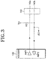
- Fig. 3 illustrates a conventional external type ear-microphone.
- An interface connector 140 mounted at the bottom of the terminal includes ports 140a and 140b for connection of the ear-microphone. Though not shown, the interface connector 140 further includes ports for a hands-free kit and ports for data communication. More specifically, when a plug 230 shown in Fig. 1B is inserted into the interface connector 140, the microphone 250 and the speaker 260 are electrically connected to the microphone amplifier AMP1 and the speaker amplifier AMP2 prepared in the vocoder 130, respectively, thus allowing the user to make a telephone conversation.
- the built-in type ear-microphone which is commonly used for a code division multiple access (CDMA) portable radio terminal, is inserted during the telephone conversation, unpleasant noises are generated. This is because the microphone is instantaneously short-circuited to the speaker while the ear-microphone is inserted.
- CDMA code division multiple access
- a GSM portable radio terminal employing a time division multiple access (TDMA) technique has the following problems in addition to the problems mentioned above.
- the external type ear-microphone is typically used for a TDMA portable radio terminal, while the built-in type ear-microphone is typically used for the CDMA portable radio terminal.
- the TDMA terminal has high instantaneous power consumption of 2 W while the CDMA terminal has low instantaneous power consumption of 0.6 W, thereby causing degradation of audio quality due to TDMA noises.
- the reason to use the external type ear-microphone for the TDMA terminal is that the TDMA terminal lacks an internal space.
- the external type ear-microphone used for the GSM portable radio terminal is unhandy to carry about and restricts movement of the user, because a ratio of the plug to the portable radio terminal in size is very high.
- the GSM terminal cannot use the interface connector for other uses.
- Nokia company has proposed a TDMA portable radio terminal which uses the built-in type ear-microphone by employing a single ended technique which is used in the CDMA portable radio terminal.
- the single ended built-in type ear-microphone is effective in detecting switching of the ear-microphone, it is susceptible to TDMA noises, causing deterioration of audio quality.
- employment of the single ended technique causes a decrease in volume of the audio.
- Fig. 4 illustrates a device for controlling connection of a single ended ear-microphone.
- the conventional device includes a 3-pole 5-node earphone jack 430 into which an earphone plug is inserted; a vocoder 400 for processing audio signals input and output to/from an earphone, and a speaker and a microphone of the terminal; a reference voltage generator 410 for generating a reference voltage; and a voltage comparator 420 for comparing a variation in voltage, happened when the earphone plug is inserted in the earphone jack 430, with the reference voltage generated from the reference voltage generator 410, to notify insertion of the earphone plug to a controller of the portable terminal. Therefore, in the TDMA portable radio terminal, it is very difficult to implement a built-in type ear-microphone which is insusceptible to the TDMA noises.
- the object of the present invention to provide a device for controlling connection of an ear-microphone for a portable radio terminal, which is handy to carry about and prevents generation of unpleasant noises even though the ear-microphone is inserted during telephone conversation.
- a device for controlling connection of a built-in type ear-microphone for a portable radio terminal comprises a vocoder including a speaker amplifier and a microphone amplifier of the portable radio terminal and an ear-microphone amplifier; first logic combination means for logically combining a signal output from the speaker amplifier and a signal output from the ear-microphone amplifier so as to prevent generation of noises due to short-circuit of a microphone signal and a speaker signal while an earphone plug is inserted in an earphone jack; a comparator for comparing an electric signal sensed at the earphone jack with a reference voltage; second logic combination means for logically combining an output of the first logic combination means and an output of the comparator to generate a jack detection signal; and a central processing unit for generating a control signal for enabling the vocoder to switch an audio signal path to the ear-microphone amplifier, upon detection of the jack detection signal during a call.
- a device for controlling connection of a built-in type ear-microphone for a time division multiple access (TDMA) portable radio terminal comprises a vocoder including positive and negative nodes for a speaker and a microphone, for processing audio signals input and output from/to the nodes; a doubled ended 4-pole 6-node earphone jack for connecting, upon insertion of an earphone plug, a positive line of an earphone microphone to a microphone positive node of the vocoder through a first node, connecting a negative line of the earphone microphone to a microphone negative node through a second node, and disconnecting the second node from a third node; and a voltage comparator for comparing a voltage input through the first or third node with a reference voltage, to detecting switching of an earphone switch and insertion of the earphone plug.
- TDMA time division multiple access
- Fig. 5 illustrates a device for controlling connection of a built-in type ear-microphone for a potable radio terminal according to a first embodiment of the present invention.
- a central processing unit (CPU, not shown) of the portable radio terminal changes an audio processing path of a vocoder 537. That is, an audio processing path connected to a speaker amplifier AMP3 and a microphone amplifier AMP5 of the terminal is switched to amplifiers AMP4 and AMP6 for the ear-microphone (or hands-free kit for vehicle).
- CPU central processing unit
- a signal input from the ear-microphone through a pin 2 of the jack 100 is amplified into two-phase signals by amplifiers AMP8 and AMP9 and then input to the microphone amplifier AMP5 in the vocoder 537.
- two-phase signals output from the speaker amplifier AMP3 for the terminal are converted into a single-phase signal by a differential amplifier AMP7 and then output to an earphone of the ear-microphone through a pin 3 of the jack 100, so that the user can hear the sound.
- a detection signal representative of the plug inserted state is output from a second AND gate G2 and then provided to the CPU.
- the second AND gate G2 ANDs an output of a first AND gate G1 and an output of a comparator COM1 to generate a jack detection signal JD3.
- the jack detection signal JD3 is an initial detection signal for generating a signal having a level appropriate for the ear-microphone.
- the comparator COM1 compares an electric signal sensed at a pin 4 in the jack 100 with a reference voltage Vref.
- the first AND gate G1 ANDs an output of the differential amplifier AMP7, which converts the two-phase signals output from the speaker amplifier AMP3 of the terminal into a single-phase signal, and a signal input from the ear-microphone through a pin 2 of the jack 100.
- Fig. 6 illustrates a device for controlling connection of a built-in type ear-microphone for a portable radio terminal according to a second embodiment of the present invention.
- the device is similar in structure to the device of Fig. 5, except that the separate amplifiers are required since single-phase signals are used. That is, in Fig. 5, the separate amplifiers AMP7, AMP8 and AMP9 are required, since the two-phase signals are used.
- Fig. 7 illustrates the connection between a TDMA portable radio terminal and a built-in type ear-microphone according to another embodiment of the present invention.
- a built-in type ear-microphone includes an earphone plug 740 which is inserted in an earphone jack of a TDMA portable radio terminal 700, a speaker 710, a microphone 730 and an earphone switch 720.
- the ear-microphone for the TDMA terminal of Fig. 7 is different from that of Fig. 1B in that the ear-microphone is inserted in the earphone jack of the TDMA terminal rather than in the interface connector. That is, the ear-microphone for the TDMA terminal of Fig.
- ear-microphone 7 is used in the same way as the ear-microphone for the CDMA terminal of Fig. 1A. This implies that the ear-microphone for the TDMA terminal according to the present invention does not require a separate chip for controlling an audio signal path. In the prior art, however, a voice path control chip is built in the plug 230 connected to the interface connector 140, causing inconvenience in carrying about and increasing the production cost.
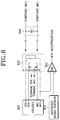
- Fig. 8 illustrates a device for controlling connection of a built-in type ear-microphone for a TDMA portable radio terminal, which can detect switching of an earphone, according to a third embodiment of the present invention.
- a vocoder 800 which is typically implemented by a single chip, compresses input/output audio signals and has speaker nodes SPK+ and SPK- and microphone nodes MIC+ and MIC-. For these nodes, designated I/O nodes are typically used.
- a 4-pole 6-node earphone jack 830 has a first node A connected to the MIC+ node of the vocoder 800, a second node B connected to the MIC- node of the vocoder 800, a third node C connected to a MIC- node of the portable radio terminal, a fourth node D connected to the a SPK- node of the portable radio terminal, a fifth node E connected to the SPK- node of the vocoder 800, and a sixth node F connected to the SPK+ node of the vocoder 800. Further, the first node A is also connected to an inverse input node (-) of a voltage comparator 820.
- the voltage comparator 820 compares input voltages and provides the results to a controller which is implemented by a microprocessor in the portable radio terminal.
- a reference voltage generator 810 generates a predetermined reference voltage and provides the generated reference voltage to the voltage comparator 820 through a non-inverse input node (+).
- An earphone which is normally inserted in an earphone jack 830, includes an earphone speaker and an earphone microphone. Further, the earphone includes an earphone switch 840 for controlling various functions of the portable terminal, such as call start and call end functions.
- the earphone switch 840 is connected between an earphone MIC+ line and an earphone MIC- line.
- an earphone speaker line is also divided into a positive (+) speaker line and a negative (-) speaker line. Since the earphone device employs the double ended technique, the speaker node, the microphone node and the earphone line are divided into positive (+) and negative (-) sides, respectively.
- the conventional built-in type ear-microphone of FIG 4 employs the single ended technique.
- the double ended technique is used to minimize a susceptibility to TDMA noises generated in the TDMA portable terminal. That is, even though instantaneous power consumption increases due to the TDMA noises, the respective positive (+) and negative (-) nodes of the speaker and the microphone cancel the noises, so that the earphone device is insusceptible to the TDMA noises.
- the double ended technique is well known in the art, so the detailed description will be avoided.
- a specific bias voltage is generated between the MIC+ node and the MIC- node of the vocoder 800.
- the MIC- node has 2.2 V and the MIC+ node has 0.3 V.
- the reference voltage generator 810 generates a predetermined reference voltage and provides the generated reference voltage to the non-inverse input node (+) of the voltage comparator 820.
- the reference voltage has a voltage level between 1 V and 1.5 V.
- the earphone switch 840 is opened (i.e., turned OFF)
- a signal from the earphone is applied to the inverse input node (-) of the voltage comparator 820 against an inherent impedance 2.2K ⁇ of the microphone lines of the earphone.
- the voltage at the inverse input node (-) becomes 0.3 V.
- the voltage comparator 820 compares a voltage at the inverse input node (-) with a voltage at the non-inverse input node (+) and provides the results to the controller, wherein the output of the voltage comparator 820 indicates that the earphone switch 840 is turned OFF.
- the earphone switch 840 when the earphone switch 840 is closed (i.e., turned ON), a bias voltage between the earphone MIC+ line and the earphone MIC- line is changed, an increased voltage level (e.g., 2.2 V) is applied to the inverse input node (-) of the voltage comparator 820.
- the voltage comparator 820 compares the applied voltage with the reference voltage received at the non-inverse input node (+), and outputs the reverse results of the switch OFF state. For example, assuming that the voltage comparator 820 outputs a high" signal when the earphone switch 840 is turned OFF, and a low" signal when the earphone switch 840 is turned ON, the voltage comparator 820 will output the low" signal to the controller.
- the controller then performs a corresponding operation according to the signal output from the voltage comparator 820.
- the corresponding operation includes call start, call end, voice recognition start functions. That is, it is possible to detect switching of the earphone switch 840 depending on the output of the voltage comparator 820.
- the above operation is performed in the state where the earphone plug is inserted in the earphone jack 830. When the earphone plug is not inserted, the operation of detecting switching of the earphone switch is not performed, thereby avoiding unnecessary power consumption.
- Fig. 9 illustrates a device for controlling connection of a built-in type ear-microphone for a TDMA portable radio terminal, which can detect insertion of an earphone, according to a fourth embodiment of the present invention.
- a vocoder 900, a reference voltage generator 910, a voltage comparator 920 and an earphone jack 930 have the same structures and functions as those in Fig. 8.
- a third node C of the earphone jack 930 is commonly connected to an inverse input node (-) of the voltage comparator 920 and a MIC- node of the terminal.
- a first node A is connected to a MIC+ node of the terminal. This connection is used to detect insertion of the earphone plug.
- the reference voltage from the reference voltage generator 910 is provided to the voltage comparator 920.
- the third node C is connected to the second node B, so that a bias voltage from the MIC- node of the vocoder 900 is applied to the inverse input node (-) of the voltage comparator 920.
- the voltage comparator 920 will output a low " signal and provide the output signal to the controller.
- the controller then set an audio signal path of the vocoder 900 to the speaker and microphone in the portable terminal body.
- fourth and fifth nodes D and E of the earphone jack 930 are disconnected from each other and the third node C is floated to 0 V.
- the voltage comparator 920 compares the floated voltage 0 V with the reference voltage and outputs a high" signal. The controller then recognizes insertion of the earphone plug and performs a corresponding operation.
- the device according to the present invention has the following advantages:
Abstract
Description
- The present invention relates generally to a portable radio terminal, and in particular, to a device for controlling connection of a built-in type ear-microphone.
- An ear-microphone used for a portable radio terminal can be classified into an internal type (or built-in type) and an external type. A built-in type ear-microphone commonly includes a three-pole type plug which is to be inserted into a jack of a portable radio terminal. An external type ear-microphone includes a plug which is to be inserted into an interface connector mounted at the bottom of the portable ratio terminal.
- Fig. 1A is a perspective view illustrating the connection between a built-in type ear-microphone and a portable radio terminal, and Fig. 1B is a perspective view illustrating the connection between an external type ear-microphone and a portable radio terminal. Fig. 2 illustrates a conventional device for controlling connection of the built-in type ear-microphone.
- Referring to Figs 1A to 2, when a
plug 200 of the ear-microphone is mechanically connected to an ear-microphone jack 100, the user can make a telephone conversation through the ear-microphone. Typically, the ear-microphone jack 100 is located at the top or side of the terminal. More specifically, as shown in Fig. 2, the ear-microphone jack 100 haspins 1, 3 and 2, which are connected to ground node G, speaker node S and microphone node M, respectively. Therefore, amicrophone 250 and aspeaker 260 of the ear-microphone are electrically connected to a microphone amplifier AMP1 and a speaker amplifier AMP2 prepared in avocoder 130, respectively, allowing the user to make a telephone conversation. A comparator COM1 compares an electric signal sensed at apin 4 in the ear-microphone jack 100 with a reference voltage Vref to generate a jack detection signal JD1 representative of whether or not theplug 200 is inserted into thejack 100. In addition, the jack detection signal JD1 is an initial detection signal for generating a signal having a level appropriate for the ear-microphone. - Fig. 3 illustrates a conventional external type ear-microphone. An
interface connector 140 mounted at the bottom of the terminal includesports 140a and 140b for connection of the ear-microphone. Though not shown, theinterface connector 140 further includes ports for a hands-free kit and ports for data communication. More specifically, when aplug 230 shown in Fig. 1B is inserted into theinterface connector 140, themicrophone 250 and thespeaker 260 are electrically connected to the microphone amplifier AMP1 and the speaker amplifier AMP2 prepared in thevocoder 130, respectively, thus allowing the user to make a telephone conversation. However, when the built-in type ear-microphone, which is commonly used for a code division multiple access (CDMA) portable radio terminal, is inserted during the telephone conversation, unpleasant noises are generated. This is because the microphone is instantaneously short-circuited to the speaker while the ear-microphone is inserted. - Meanwhile, a GSM portable radio terminal employing a time division multiple access (TDMA) technique has the following problems in addition to the problems mentioned above.
- In general, the external type ear-microphone is typically used for a TDMA portable radio terminal, while the built-in type ear-microphone is typically used for the CDMA portable radio terminal. This is because the TDMA terminal has high instantaneous power consumption of 2 W while the CDMA terminal has low instantaneous power consumption of 0.6 W, thereby causing degradation of audio quality due to TDMA noises. In addition, the reason to use the external type ear-microphone for the TDMA terminal is that the TDMA terminal lacks an internal space. However, the external type ear-microphone used for the GSM portable radio terminal is unhandy to carry about and restricts movement of the user, because a ratio of the plug to the portable radio terminal in size is very high.
- In addition, while using the ear-microphone, the GSM terminal cannot use the interface connector for other uses. For reference, to solve the problem of the external ear-microphone, Nokia company has proposed a TDMA portable radio terminal which uses the built-in type ear-microphone by employing a single ended technique which is used in the CDMA portable radio terminal. Although the single ended built-in type ear-microphone is effective in detecting switching of the ear-microphone, it is susceptible to TDMA noises, causing deterioration of audio quality. Unfavourably, employment of the single ended technique causes a decrease in volume of the audio.
- Fig. 4 illustrates a device for controlling connection of a single ended ear-microphone. Referring to Fig. 4, the conventional device includes a 3-pole 5-
node earphone jack 430 into which an earphone plug is inserted; avocoder 400 for processing audio signals input and output to/from an earphone, and a speaker and a microphone of the terminal; areference voltage generator 410 for generating a reference voltage; and avoltage comparator 420 for comparing a variation in voltage, happened when the earphone plug is inserted in theearphone jack 430, with the reference voltage generated from thereference voltage generator 410, to notify insertion of the earphone plug to a controller of the portable terminal. Therefore, in the TDMA portable radio terminal, it is very difficult to implement a built-in type ear-microphone which is insusceptible to the TDMA noises. - Therefore, there is a demand for a device for controlling connection of a built-in type ear-microphone, which can prevent the unpleasant noises generated in the CDMA terminal and have the reduced susceptibility to the TDMA noises generated in the GSM terminal.
- It is, therefore, the object of the present invention to provide a device for controlling connection of an ear-microphone for a portable radio terminal, which is handy to carry about and prevents generation of unpleasant noises even though the ear-microphone is inserted during telephone conversation.
- It is aspect of the present invention to provide a device for connecting an ear-microphone, which can be built in a TDMA portable radio terminal and minimize a susceptibility to TDMA noises.
- It is another aspect of the present invention to provide an earphone device which can detect switching and insertion of an earphone.
- It is still another aspect of the present invention to provide a device for controlling connection of a double ended ear-microphone for a TDMA portable radio terminal.
- In accordance with one aspect of the present invention, a device for controlling connection of a built-in type ear-microphone for a portable radio terminal, comprises a vocoder including a speaker amplifier and a microphone amplifier of the portable radio terminal and an ear-microphone amplifier; first logic combination means for logically combining a signal output from the speaker amplifier and a signal output from the ear-microphone amplifier so as to prevent generation of noises due to short-circuit of a microphone signal and a speaker signal while an earphone plug is inserted in an earphone jack; a comparator for comparing an electric signal sensed at the earphone jack with a reference voltage; second logic combination means for logically combining an output of the first logic combination means and an output of the comparator to generate a jack detection signal; and a central processing unit for generating a control signal for enabling the vocoder to switch an audio signal path to the ear-microphone amplifier, upon detection of the jack detection signal during a call.
- In another aspect of the present invention, a device for controlling connection of a built-in type ear-microphone for a time division multiple access (TDMA) portable radio terminal, comprises a vocoder including positive and negative nodes for a speaker and a microphone, for processing audio signals input and output from/to the nodes; a doubled ended 4-pole 6-node earphone jack for connecting, upon insertion of an earphone plug, a positive line of an earphone microphone to a microphone positive node of the vocoder through a first node, connecting a negative line of the earphone microphone to a microphone negative node through a second node, and disconnecting the second node from a third node; and a voltage comparator for comparing a voltage input through the first or third node with a reference voltage, to detecting switching of an earphone switch and insertion of the earphone plug.
- The above and other objects, features and advantages of the present invention will become more apparent from the following detailed description when taken in conjunction with the accompanying drawings in which:
- Fig. 1A is a perspective view illustrating the connection between a portable radio terminal and a built-in type ear-microphone;
- Fig. 1B is a perspective view illustrating the connection between a portable radio terminal and an external type ear-microphone;
- Fig. 2 is a diagram illustrating a conventional device for controlling connection of a built-in type ear-microphone;
- Fig. 3 is a diagram illustrating a conventional device for controlling connection of an external type ear-microphone;
- Fig. 4 is a diagram illustrating a conventional device for controlling connection of a single ended ear-microphone for a TDMA portable radio terminal;
- Fig. 5 is a diagram illustrating a device for connecting a built-in type ear-microphone to a portable radio terminal according to a first embodiment of the present invention;
- Fig. 6 is a diagram illustrating a device for connecting a built-in type ear-microphone to a portable radio terminal according to a second embodiment of the present invention;
- Fig. 7 is a diagram illustrating the connection between a TDMA portable radio terminal and a built-in type ear-microphone according to an embodiment of the present invention;
- Fig. 8 is a diagram illustrating a device for controlling connection of a built-in type ear-microphone for a TDMA portable radio terminal, which can detect switching of an earphone, according to a third embodiment of the present invention; and
- Fig. 9 is a diagram illustrating a device for controlling connection of a built-in type ear-microphone for a TDMA portable radio terminal, which can detect insertion of an earphone, according to a fourth embodiment of the present invention.
-
- A preferred embodiment of the present invention will be described herein below with reference to the accompanying drawings. In the following description, well-known functions or constructions are not described in detail since they would obscure the invention in unnecessary detail.
- Fig. 5 illustrates a device for controlling connection of a built-in type ear-microphone for a potable radio terminal according to a first embodiment of the present invention. Upon detecting insertion of a
plug 200 into ajack 100 during a call, a central processing unit (CPU, not shown) of the portable radio terminal changes an audio processing path of a vocoder 537. That is, an audio processing path connected to a speaker amplifier AMP3 and a microphone amplifier AMP5 of the terminal is switched to amplifiers AMP4 and AMP6 for the ear-microphone (or hands-free kit for vehicle). In the state where the audio processing path is switched, a signal input from the ear-microphone through a pin 2 of thejack 100 is amplified into two-phase signals by amplifiers AMP8 and AMP9 and then input to the microphone amplifier AMP5 in the vocoder 537. In addition, two-phase signals output from the speaker amplifier AMP3 for the terminal are converted into a single-phase signal by a differential amplifier AMP7 and then output to an earphone of the ear-microphone through apin 3 of thejack 100, so that the user can hear the sound. In the meantime, when theplug 200 is inserted in thejack 100, a detection signal representative of the plug inserted state is output from a second AND gate G2 and then provided to the CPU. That is, the second AND gate G2 ANDs an output of a first AND gate G1 and an output of a comparator COM1 to generate a jack detection signal JD3. The jack detection signal JD3 is an initial detection signal for generating a signal having a level appropriate for the ear-microphone. The comparator COM1 compares an electric signal sensed at apin 4 in thejack 100 with a reference voltage Vref. The first AND gate G1 ANDs an output of the differential amplifier AMP7, which converts the two-phase signals output from the speaker amplifier AMP3 of the terminal into a single-phase signal, and a signal input from the ear-microphone through a pin 2 of thejack 100. By providing the first AND gate G1 connected as stated above, it is possible to avoid the unpleasant noises which are generated due to short-circuit between a microphone signal and a speaker signal while theplug 200 is inserted in thejack 100. - Fig. 6 illustrates a device for controlling connection of a built-in type ear-microphone for a portable radio terminal according to a second embodiment of the present invention. As illustrated, the device is similar in structure to the device of Fig. 5, except that the separate amplifiers are required since single-phase signals are used. That is, in Fig. 5, the separate amplifiers AMP7, AMP8 and AMP9 are required, since the two-phase signals are used. In accordance with the above embodiments, it is possible to provide a device for controlling connection of a built-in type ear-microphone for a CDMA portable radio terminal, which is handy to carry about and can prevent generation of the unpleasant noises even though the plug is inserted during a call.
- Next, a description will be made with regard to a device for controlling connection of a built-in type ear-microphone for a TDMA portable radio terminal, which can minimize a susceptibility to TDMA noises, with reference to Figs 7, 8 and 9.
- Fig. 7 illustrates the connection between a TDMA portable radio terminal and a built-in type ear-microphone according to another embodiment of the present invention. Referring to Fig. 7, a built-in type ear-microphone includes an
earphone plug 740 which is inserted in an earphone jack of a TDMAportable radio terminal 700, aspeaker 710, amicrophone 730 and anearphone switch 720. The ear-microphone for the TDMA terminal of Fig. 7 is different from that of Fig. 1B in that the ear-microphone is inserted in the earphone jack of the TDMA terminal rather than in the interface connector. That is, the ear-microphone for the TDMA terminal of Fig. 7 is used in the same way as the ear-microphone for the CDMA terminal of Fig. 1A. This implies that the ear-microphone for the TDMA terminal according to the present invention does not require a separate chip for controlling an audio signal path. In the prior art, however, a voice path control chip is built in theplug 230 connected to theinterface connector 140, causing inconvenience in carrying about and increasing the production cost. - Fig. 8 illustrates a device for controlling connection of a built-in type ear-microphone for a TDMA portable radio terminal, which can detect switching of an earphone, according to a third embodiment of the present invention. Referring to Fig. 8, a
vocoder 800, which is typically implemented by a single chip, compresses input/output audio signals and has speaker nodes SPK+ and SPK- and microphone nodes MIC+ and MIC-. For these nodes, designated I/O nodes are typically used. A 4-pole 6-node earphone jack 830 has a first node A connected to the MIC+ node of thevocoder 800, a second node B connected to the MIC- node of thevocoder 800, a third node C connected to a MIC- node of the portable radio terminal, a fourth node D connected to the a SPK- node of the portable radio terminal, a fifth node E connected to the SPK- node of thevocoder 800, and a sixth node F connected to the SPK+ node of thevocoder 800. Further, the first node A is also connected to an inverse input node (-) of avoltage comparator 820. Thevoltage comparator 820 compares input voltages and provides the results to a controller which is implemented by a microprocessor in the portable radio terminal. Areference voltage generator 810 generates a predetermined reference voltage and provides the generated reference voltage to thevoltage comparator 820 through a non-inverse input node (+). An earphone, which is normally inserted in anearphone jack 830, includes an earphone speaker and an earphone microphone. Further, the earphone includes anearphone switch 840 for controlling various functions of the portable terminal, such as call start and call end functions. Theearphone switch 840 is connected between an earphone MIC+ line and an earphone MIC- line. Though not illustrated, an earphone speaker line is also divided into a positive (+) speaker line and a negative (-) speaker line. Since the earphone device employs the double ended technique, the speaker node, the microphone node and the earphone line are divided into positive (+) and negative (-) sides, respectively. - The conventional built-in type ear-microphone of FIG 4 employs the single ended technique. In the embodiment of the present invention, the double ended technique is used to minimize a susceptibility to TDMA noises generated in the TDMA portable terminal. That is, even though instantaneous power consumption increases due to the TDMA noises, the respective positive (+) and negative (-) nodes of the speaker and the microphone cancel the noises, so that the earphone device is insusceptible to the TDMA noises. The double ended technique is well known in the art, so the detailed description will be avoided.
- Now, a description will be made with regard to an operation of detecting switching of the earphone in the device for controlling connection of the built-in type ear-microphone for the TDMA portable radio terminal. When the earphone plug is inserted in the
earphone jack 830, a specific bias voltage is generated between the MIC+ node and the MIC- node of thevocoder 800. For example, in a common vocoder, the MIC- node has 2.2 V and the MIC+ node has 0.3 V. Thereference voltage generator 810 generates a predetermined reference voltage and provides the generated reference voltage to the non-inverse input node (+) of thevoltage comparator 820. For example, the reference voltage has a voltage level between 1 V and 1.5 V. In this state, if theearphone switch 840 is opened (i.e., turned OFF), a signal from the earphone is applied to the inverse input node (-) of thevoltage comparator 820 against an inherent impedance 2.2KΩ of the microphone lines of the earphone. The voltage at the inverse input node (-) becomes 0.3 V. Thevoltage comparator 820 then compares a voltage at the inverse input node (-) with a voltage at the non-inverse input node (+) and provides the results to the controller, wherein the output of thevoltage comparator 820 indicates that theearphone switch 840 is turned OFF. - Alternatively, when the
earphone switch 840 is closed (i.e., turned ON), a bias voltage between the earphone MIC+ line and the earphone MIC- line is changed, an increased voltage level (e.g., 2.2 V) is applied to the inverse input node (-) of thevoltage comparator 820. Thevoltage comparator 820 then compares the applied voltage with the reference voltage received at the non-inverse input node (+), and outputs the reverse results of the switch OFF state. For example, assuming that thevoltage comparator 820 outputs ahigh" signal when the
earphone switch 840 is turned OFF, and aearphone switch 840 is turned ON, thevoltage comparator 820 will output thevoltage comparator 820. For example, the corresponding operation stated above includes call start, call end, voice recognition start functions. That is, it is possible to detect switching of theearphone switch 840 depending on the output of thevoltage comparator 820. The above operation is performed in the state where the earphone plug is inserted in theearphone jack 830. When the earphone plug is not inserted, the operation of detecting switching of the earphone switch is not performed, thereby avoiding unnecessary power consumption. - Fig. 9 illustrates a device for controlling connection of a built-in type ear-microphone for a TDMA portable radio terminal, which can detect insertion of an earphone, according to a fourth embodiment of the present invention. In Fig. 9, a
vocoder 900, areference voltage generator 910, avoltage comparator 920 and anearphone jack 930 have the same structures and functions as those in Fig. 8. However, a third node C of theearphone jack 930 is commonly connected to an inverse input node (-) of thevoltage comparator 920 and a MIC- node of the terminal. Further, a first node A is connected to a MIC+ node of the terminal. This connection is used to detect insertion of the earphone plug. - A description will now be made regarding an operation of detecting insertion of the earphone according to an embodiment of the present invention. First, the reference voltage from the
reference voltage generator 910 is provided to thevoltage comparator 920. Further, when the earphone plug is not inserted in theearphone jack 930, the third node C is connected to the second node B, so that a bias voltage from the MIC- node of thevocoder 900 is applied to the inverse input node (-) of thevoltage comparator 920. At this point, since the voltage level applied to the inverse input node (-) of thevoltage comparator 920 is higher than the reference voltage on the non-inverse input node (+), thevoltage comparator 920 will output avocoder 900 to the speaker and microphone in the portable terminal body. In the meantime, when the earphone plug is inserted in theearphone jack 930, fourth and fifth nodes D and E of theearphone jack 930 are disconnected from each other and the third node C is floated to 0 V. Thevoltage comparator 920 compares the floated voltage 0 V with the reference voltage and outputs a - As described above, the device according to the present invention has the following advantages:
- 1) It is possible to prevent generation of the unpleasant noises, even though the ear-microphone is inserted in the portable radio terminal during a call.
- 2) It is convenient to carry the portable radio terminal with ear-microphone inserted therein.
- 3) The built-in type ear-microphone can be used for a TDMA portable radio terminal and is insusceptible to the CDMA noses.
- 4) The device for controlling connection of the built-in type ear-microphone can detect insertion of the earphone and switching of the earphone.
-
Claims (2)
- A device for controlling connection of a built-in type ear-microphone for a portable radio terminal, comprising:a vocoder including a speaker amplifier and a microphone amplifier of the portable radio terminal and an ear-microphone amplifier;first logic combination means for logically combining a signal output from the speaker amplifier and a signal output from the ear-microphone amplifier so as to prevent generation of noises due to short-circuit of a microphone signal and a speaker signal while an earphone plug is inserted in an earphone jack;a comparator for comparing an electric signal sensed at the earphone jack with a reference voltage;second logic combination means for logically combining an output of the first logic combination means and an output of the comparator to generate a jack detection signal; anda central processing unit for generating a control signal for enabling the vocoder to switch an audio signal path to the ear-microphone amplifier, upon detection of the jack detection signal during a call.
- A device for controlling connection of a built-in type ear-microphone for a time division multiple access (TDMA) portable radio terminal, comprising:a vocoder including positive and negative nodes for a speaker and a microphone, for processing audio signals input and output from/to the nodes;a doubled ended 4-pole 6-node earphone jack for connecting, upon insertion of an earphone plug, a positive line of an earphone microphone to a microphone positive node of the vocoder through a first node, connecting a negative line of the earphone microphone to a microphone negative node through a second node, and disconnecting the second node from a third node; anda voltage comparator for comparing a voltage input through the first or third node with a reference voltage, to detecting switching of an earphone switch and insertion of the earphone plug.
Applications Claiming Priority (4)
| Application Number | Priority Date | Filing Date | Title |
|---|---|---|---|
| KR9847903 | 1998-11-07 | ||
| KR9847904 | 1998-11-07 | ||
| KR1019980047904A KR100557155B1 (en) | 1998-11-07 | 1998-11-07 | Circuit for controlling the built-in earphone-microphone connection in portable wireless terminal |
| KR1019980047903A KR100322049B1 (en) | 1998-11-07 | 1998-11-07 | Built-in earphone device of mobile terminal with time division multiple access method |
Publications (2)
| Publication Number | Publication Date |
|---|---|
| EP0999721A2 true EP0999721A2 (en) | 2000-05-10 |
| EP0999721A3 EP0999721A3 (en) | 2003-05-21 |
Family
ID=26634308
Family Applications (1)
| Application Number | Title | Priority Date | Filing Date |
|---|---|---|---|
| EP99122154A Ceased EP0999721A3 (en) | 1998-11-07 | 1999-11-05 | Device for controlling connection of built-in type ear-microphone for portable radio terminal |
Country Status (2)
| Country | Link |
|---|---|
| US (1) | US6397087B1 (en) |
| EP (1) | EP0999721A3 (en) |
Cited By (5)
| Publication number | Priority date | Publication date | Assignee | Title |
|---|---|---|---|---|
| DE102007046438A1 (en) * | 2007-09-28 | 2008-10-30 | Siemens Audiologische Technik Gmbh | Portable Behind-the-ear-hearing aid device system, has commercial jack plug used as audio input for detachable connection with stereo jack, and electrical detector circuit automatically identifying inserted jack |
| CN102395084A (en) * | 2011-11-11 | 2012-03-28 | 杭州硅星科技有限公司 | Headset circuit |
| CN102595299A (en) * | 2010-11-22 | 2012-07-18 | 快捷半导体(苏州)有限公司 | Accessory detection system and method |
| EP3122064A1 (en) * | 2015-07-20 | 2017-01-25 | Samsung Electronics Co., Ltd. | Method and apparatus for controlling output based on type of connector |
| CN106537932A (en) * | 2014-07-23 | 2017-03-22 | 三星电子株式会社 | Earset and earset operation method |
Families Citing this family (60)
| Publication number | Priority date | Publication date | Assignee | Title |
|---|---|---|---|---|
| JP3855015B2 (en) * | 1999-02-25 | 2006-12-06 | 株式会社ノボル電機製作所 | Telephone with handset presser |
| JP2001136251A (en) * | 1999-11-05 | 2001-05-18 | Matsushita Electric Ind Co Ltd | Folding portable telephone system |
| DE60037878T2 (en) * | 2000-05-11 | 2009-01-22 | Lucent Technologies Inc. | Mobile station for telecommunication system |
| US20040125979A1 (en) * | 2001-08-07 | 2004-07-01 | Josef Elidan | Earphone for a cellular phone |
| KR100422475B1 (en) * | 2001-09-25 | 2004-03-11 | 에스케이텔레텍주식회사 | Speaker module connectable to an ear-jack and conversation method thereby |
| US20030060242A1 (en) * | 2001-09-27 | 2003-03-27 | Kevin Dotzler | Microphone switchover circuit |
| KR100396267B1 (en) * | 2001-10-24 | 2003-09-02 | 삼성전자주식회사 | Method for confirming ear microphone state in communication terminal |
| WO2003051022A1 (en) * | 2001-12-12 | 2003-06-19 | Gary Ragner | Audio extension for wireless communication devices |
| US7373182B2 (en) * | 2002-03-01 | 2008-05-13 | Varia Mobil Llc | Wireless mobile phone including a headset |
| US7187948B2 (en) * | 2002-04-09 | 2007-03-06 | Skullcandy, Inc. | Personal portable integrator for music player and mobile phone |
| US6771780B2 (en) * | 2002-04-22 | 2004-08-03 | Chi-Lin Hong | Tri-functional dual earphone device |
| US20040204170A1 (en) * | 2002-05-01 | 2004-10-14 | Mkhitarian Harry A. | Mobile phone battery pack and battery cover with earphone-microphone earpiece jack |
| US7406339B2 (en) * | 2002-08-05 | 2008-07-29 | Qualcomm Incorporated | On-chip detection circuit off-chip mechanical switch's open and close actions |
| TW589527B (en) * | 2002-09-20 | 2004-06-01 | Realtek Semiconductor Corp | Device and method for automatically recognizing output and input of analog signal |
| TW595239B (en) * | 2003-01-28 | 2004-06-21 | Htc Corp | Detection circuit to detect the earphone type plugged into the insertion hole |
| TWI226731B (en) * | 2003-03-26 | 2005-01-11 | Realtek Semiconductor Corp | Multi-jacks detector |
| KR20040090577A (en) * | 2003-04-17 | 2004-10-26 | 주식회사 팬택앤큐리텔 | The Apparatus and Method to Sensing Strobo of Wireless Communication Terminal Automatically |
| US6928176B2 (en) * | 2003-05-13 | 2005-08-09 | Princeton Technology Corporation | Switching circuit built in IC for earphone and loudspeaker of portable information device |
| TW594544B (en) * | 2003-05-14 | 2004-06-21 | Benq Corp | Interface device for automatically determining peripherals and electronic device having such a function |
| US6902412B2 (en) * | 2003-08-26 | 2005-06-07 | Motorola, Inc. | Apparatus for intrinsically safe power interface |
| US7349546B2 (en) * | 2003-09-04 | 2008-03-25 | Kyocera Wireless Corp. | System and method for identifying a headset type in an electrical device |
| TW200514415A (en) * | 2003-10-08 | 2005-04-16 | qing-chang Ou | Multiple audio-source on-line real-time listening and recording device |
| KR100540835B1 (en) * | 2003-10-29 | 2006-01-10 | 주식회사 팬택앤큐리텔 | Apparatus For Ear_Handfree Signal Processing In The Mobile Communication Terminal |
| US7023983B2 (en) * | 2003-12-30 | 2006-04-04 | Qualcomm Incorporated | Versatile circuit for interfacing with audio headsets |
| KR100663511B1 (en) * | 2004-01-24 | 2007-01-02 | 삼성전자주식회사 | Circuit for supplying earphone microphone bias power for ear-mic phone in mobile terminal |
| US20060013410A1 (en) * | 2004-04-20 | 2006-01-19 | Wurtz Michael J | Mobile-telephone adapters for automatic-noise-reduction headphones |
| KR100559039B1 (en) * | 2004-05-18 | 2006-03-10 | 주식회사 팬택 | Apparatus and Method of Managing Voice in the Mobile Communication Terminal |
| US8412268B2 (en) * | 2004-10-25 | 2013-04-02 | Nokia Corporation | Detection, identification and operation of pheripherals connected via an audio/video-plug to an electronic device |
| WO2006078378A2 (en) * | 2005-01-18 | 2006-07-27 | Atmel Corporation | Method and topology to switch an output stage in a class ab audio amplifier for wireless applications |
| FR2881005B1 (en) * | 2005-01-18 | 2007-03-30 | Atmel Corp | METHOD AND TOPOLOGY FOR SWITCHING A OUTPUT RANGE IN A CLASS AB AUDIO AMPLIFIER FOR WIRELESS APPLICATIONS |
| US20060183509A1 (en) * | 2005-02-16 | 2006-08-17 | Shuyong Shao | DC power source for an accessory of a portable communication device |
| US20060218327A1 (en) * | 2005-03-23 | 2006-09-28 | Dell Products L.P. | Information handling system including detection of an audio input device |
| US20060223580A1 (en) * | 2005-03-31 | 2006-10-05 | Antonio Franklin P | Mobile device interface for input devices using existing mobile device connectors |
| KR101191263B1 (en) * | 2005-10-19 | 2012-10-16 | 엘지전자 주식회사 | A Method Informing If Speaker-Phone Function is Used |
| EP1942637B1 (en) * | 2005-10-26 | 2016-01-27 | NEC Corporation | Phone terminal and signal processing method |
| KR101177948B1 (en) * | 2006-01-13 | 2012-08-28 | 삼성전자주식회사 | PoC SYSTEM AND MOBILE APARATUS AND METHOD FOR ARAMING A MEDIA TRANSFER TIME INFORMATION IN PoC SYSTEM |
| US7912501B2 (en) | 2007-01-05 | 2011-03-22 | Apple Inc. | Audio I/O headset plug and plug detection circuitry |
| US8144915B2 (en) * | 2007-01-06 | 2012-03-27 | Apple Inc. | Wired headset with integrated switch |
| US8600080B2 (en) * | 2008-01-14 | 2013-12-03 | Apple Inc. | Methods for communicating with electronic device accessories |
| US8831680B2 (en) * | 2008-01-31 | 2014-09-09 | Qualcomm Incorporated | Flexible audio control in mobile computing device |
| US8861743B2 (en) * | 2008-05-30 | 2014-10-14 | Apple Inc. | Headset microphone type detect |
| KR20100034229A (en) * | 2008-09-23 | 2010-04-01 | 삼성전자주식회사 | Potable device including earphone circuit and operation method using the same |
| JP4612728B2 (en) * | 2009-06-09 | 2011-01-12 | 株式会社東芝 | Audio output device and audio processing system |
| CN101719610A (en) * | 2009-12-30 | 2010-06-02 | 华为终端有限公司 | Wired earphone compatible method and device |
| CN102740180A (en) * | 2011-04-01 | 2012-10-17 | 富泰华工业(深圳)有限公司 | Broadcasting method used in broadcasting apparatus |
| CN102740185A (en) * | 2011-04-01 | 2012-10-17 | 富泰华工业(深圳)有限公司 | Audio device and earphone plug-pull silencing method thereof |
| US8616214B2 (en) | 2011-04-06 | 2013-12-31 | Kimberly-Clark Worldwide, Inc. | Earplug having a resilient core structure |
| CN102395069A (en) * | 2011-08-22 | 2012-03-28 | 华为终端有限公司 | Method for being compatible with earphones with different plug types, apparatus and terminal equipment |
| US9031253B2 (en) * | 2011-12-16 | 2015-05-12 | Qualcomm Incorporated | Plug insertion detection |
| KR101832832B1 (en) * | 2011-12-26 | 2018-02-28 | 삼성전자주식회사 | Apparatus and method for charging battery pack in portable terminal |
| JP5745476B2 (en) * | 2012-08-08 | 2015-07-08 | ビートロボ, インコーポレーテッドBeatrobo, Inc. | Connected device, application program, and content acquisition system |
| KR101937839B1 (en) | 2012-08-29 | 2019-04-10 | 삼성전자 주식회사 | Ear-phone Connecting Interface and Portable Device including the same, and Operating Method thereof |
| CN103634106A (en) * | 2012-08-29 | 2014-03-12 | 北京同方微电子有限公司 | Self-adaptation audio frequency intelligent code key and realization method thereof |
| KR20140047201A (en) * | 2012-10-08 | 2014-04-22 | 삼성전자주식회사 | Device and method for detecting insertion of ear-mic phone in terminal |
| US9681241B2 (en) * | 2013-02-26 | 2017-06-13 | Blackberry Limited | Apparatus, systems and methods for detecting insertion or removal of an audio accessory from an electronic device |
| USD780726S1 (en) * | 2015-12-04 | 2017-03-07 | Howard Wang | Wireless adapter |
| KR102395343B1 (en) | 2016-02-04 | 2022-05-09 | 삼성전자주식회사 | Apparatus for preventing noise in an electronic device |
| US9813800B2 (en) * | 2016-03-11 | 2017-11-07 | Terry Stringer | Audio surveillance system |
| ES2690155A1 (en) * | 2017-05-17 | 2018-11-19 | Juan Mondejar Capsir | Communication device adherable to clothing (Machine-translation by Google Translate, not legally binding) |
| CN114974320A (en) * | 2021-02-24 | 2022-08-30 | 瑞昱半导体股份有限公司 | Control circuit and control method of audio adapter |
Citations (1)
| Publication number | Priority date | Publication date | Assignee | Title |
|---|---|---|---|---|
| US5257413A (en) * | 1991-10-10 | 1993-10-26 | Motorola, Inc. | Option selection method and apparatus |
Family Cites Families (5)
| Publication number | Priority date | Publication date | Assignee | Title |
|---|---|---|---|---|
| SE466427B (en) * | 1990-06-25 | 1992-02-10 | Ericsson Telefon Ab L M | HAND RELEASE MODULE FOR A MOBILE PHONE |
| JPH07203582A (en) * | 1994-01-06 | 1995-08-04 | Uniden Corp | Headphone and earphone sharing circuit |
| JP3656334B2 (en) * | 1996-09-05 | 2005-06-08 | ソニー株式会社 | Stereo audio / video device connection device |
| US6181801B1 (en) * | 1997-04-03 | 2001-01-30 | Resound Corporation | Wired open ear canal earpiece |
| US5978689A (en) * | 1997-07-09 | 1999-11-02 | Tuoriniemi; Veijo M. | Personal portable communication and audio system |
-
1999
- 1999-11-05 EP EP99122154A patent/EP0999721A3/en not_active Ceased
- 1999-11-08 US US09/436,290 patent/US6397087B1/en not_active Expired - Lifetime
Patent Citations (1)
| Publication number | Priority date | Publication date | Assignee | Title |
|---|---|---|---|---|
| US5257413A (en) * | 1991-10-10 | 1993-10-26 | Motorola, Inc. | Option selection method and apparatus |
Cited By (13)
| Publication number | Priority date | Publication date | Assignee | Title |
|---|---|---|---|---|
| DE102007046438A1 (en) * | 2007-09-28 | 2008-10-30 | Siemens Audiologische Technik Gmbh | Portable Behind-the-ear-hearing aid device system, has commercial jack plug used as audio input for detachable connection with stereo jack, and electrical detector circuit automatically identifying inserted jack |
| CN102595299A (en) * | 2010-11-22 | 2012-07-18 | 快捷半导体(苏州)有限公司 | Accessory detection system and method |
| US9014388B2 (en) | 2010-11-22 | 2015-04-21 | Fairchild Semiconductor Corporation | Enable and disable comparator voltage reference |
| CN102595299B (en) * | 2010-11-22 | 2015-09-23 | 快捷半导体(苏州)有限公司 | accessory detection system and method |
| US9635453B2 (en) | 2010-11-22 | 2017-04-25 | Fairchild Semiconductor Corporation | Enable and disable comparator voltage reference |
| US10142751B2 (en) | 2010-11-22 | 2018-11-27 | Fairchild Semiconductor Corporation | Enable and disable comparator voltage reference |
| CN102395084A (en) * | 2011-11-11 | 2012-03-28 | 杭州硅星科技有限公司 | Headset circuit |
| CN102395084B (en) * | 2011-11-11 | 2014-05-14 | 杭州硅星科技有限公司 | Headset circuit |
| US10225642B2 (en) | 2014-07-23 | 2019-03-05 | Samsung Electronics Co., Ltd. | Earset and earset operation method |
| CN106537932A (en) * | 2014-07-23 | 2017-03-22 | 三星电子株式会社 | Earset and earset operation method |
| CN106537932B (en) * | 2014-07-23 | 2019-05-28 | 三星电子株式会社 | Earphone and earphone operating method |
| EP3122064A1 (en) * | 2015-07-20 | 2017-01-25 | Samsung Electronics Co., Ltd. | Method and apparatus for controlling output based on type of connector |
| US9949024B2 (en) | 2015-07-20 | 2018-04-17 | Samsung Electronics Co., Ltd | Method and apparatus for controlling output based on type of connector |
Also Published As
| Publication number | Publication date |
|---|---|
| EP0999721A3 (en) | 2003-05-21 |
| US6397087B1 (en) | 2002-05-28 |
Similar Documents
| Publication | Publication Date | Title |
|---|---|---|
| EP0999721A2 (en) | Device for controlling connection of built-in type ear-microphone for portable radio terminal | |
| US8111841B2 (en) | Audio input/output device and method for switching input/output functions | |
| US5802167A (en) | Hands-free device for use with a cellular telephone in a car to permit hands-free operation of the cellular telephone | |
| US9485580B1 (en) | Headset with microphone and wired remote control | |
| JP3349449B2 (en) | Adapter for earphone and microphone set | |
| US7340284B2 (en) | Device for connecting ear-microphone to mobile phone through interface connector thereof | |
| JP2001127855A (en) | Open/close angle detector and folding equipment | |
| CN1197406C (en) | Mobile terminal and earphone | |
| KR20070022442A (en) | Mobile phone had a function of blocking the Pop-Up Noise when an ear phone connected with the mobile phone | |
| JPH07203582A (en) | Headphone and earphone sharing circuit | |
| JP3398699B2 (en) | Mobile terminal device | |
| KR100557155B1 (en) | Circuit for controlling the built-in earphone-microphone connection in portable wireless terminal | |
| JP2003264885A (en) | Headphone output controller and mobile phone using the same | |
| US20050111670A1 (en) | Stereo audio headset interface and method that is compatible with mono headsets | |
| JP3878884B2 (en) | Jack circuit, portable electronic device and telephone using the same | |
| KR200226159Y1 (en) | Mobile Phone | |
| US7120260B2 (en) | Jack circuit and portable type electronic apparatus and telephone set using the same | |
| KR100455148B1 (en) | Short preventing circuit of mobile information terminal of four port jack | |
| JP2005191651A (en) | Cellular phone system | |
| KR100393812B1 (en) | Switch addition apparatus and method for remote controller | |
| KR100322049B1 (en) | Built-in earphone device of mobile terminal with time division multiple access method | |
| KR100268711B1 (en) | Portable mobile telephone | |
| KR100352329B1 (en) | Ear phone circuit for the improvement of stand-by time for mobile handset | |
| KR100630205B1 (en) | Apparatus for detecting earphone plug | |
| KR100258218B1 (en) | Apparatus and method for connecting plug |
Legal Events
| Date | Code | Title | Description |
|---|---|---|---|
| PUAI | Public reference made under article 153(3) epc to a published international application that has entered the european phase |
Free format text: ORIGINAL CODE: 0009012 |
|
| 17P | Request for examination filed |
Effective date: 19991105 |
|
| AK | Designated contracting states |
Kind code of ref document: A2 Designated state(s): AT BE CH CY DE DK ES FI FR GB GR IE IT LI LU MC NL PT SE |
|
| AX | Request for extension of the european patent |
Free format text: AL;LT;LV;MK;RO;SI |
|
| PUAL | Search report despatched |
Free format text: ORIGINAL CODE: 0009013 |
|
| AK | Designated contracting states |
Designated state(s): AT BE CH CY DE DK ES FI FR GB GR IE IT LI LU MC NL PT SE |
|
| AX | Request for extension of the european patent |
Extension state: AL LT LV MK RO SI |
|
| RIC1 | Information provided on ipc code assigned before grant |
Ipc: 7H 04M 1/60 B Ipc: 7H 04R 1/10 A |
|
| AKX | Designation fees paid |
Designated state(s): DE FR GB |
|
| 17Q | First examination report despatched |
Effective date: 20071008 |
|
| RAP1 | Party data changed (applicant data changed or rights of an application transferred) |
Owner name: SAMSUNG ELECTRONICS CO., LTD. |
|
| RIC1 | Information provided on ipc code assigned before grant |
Ipc: H04R 1/10 20060101ALI20130122BHEP Ipc: H04M 1/60 20060101AFI20130122BHEP Ipc: H04B 1/38 20060101ALI20130122BHEP Ipc: H04M 1/05 20060101ALI20130122BHEP |
|
| STAA | Information on the status of an ep patent application or granted ep patent |
Free format text: STATUS: THE APPLICATION HAS BEEN REFUSED |
|
| 18R | Application refused |
Effective date: 20140116 |