EP0999633A2 - Earth-fault protection for electricity network - Google Patents
Earth-fault protection for electricity network Download PDFInfo
- Publication number
- EP0999633A2 EP0999633A2 EP99660172A EP99660172A EP0999633A2 EP 0999633 A2 EP0999633 A2 EP 0999633A2 EP 99660172 A EP99660172 A EP 99660172A EP 99660172 A EP99660172 A EP 99660172A EP 0999633 A2 EP0999633 A2 EP 0999633A2
- Authority
- EP
- European Patent Office
- Prior art keywords
- feeder
- earth
- current
- phase
- fault
- Prior art date
- Legal status (The legal status is an assumption and is not a legal conclusion. Google has not performed a legal analysis and makes no representation as to the accuracy of the status listed.)
- Granted
Links
- 230000005611 electricity Effects 0.000 title claims abstract description 38
- 230000004224 protection Effects 0.000 title claims description 66
- 238000000034 method Methods 0.000 claims abstract description 46
- 230000008859 change Effects 0.000 claims description 18
- 230000007423 decrease Effects 0.000 claims description 16
- 238000001514 detection method Methods 0.000 claims description 7
- 230000010363 phase shift Effects 0.000 claims 20
- 238000011144 upstream manufacturing Methods 0.000 claims 7
- 238000012544 monitoring process Methods 0.000 claims 3
- 230000015556 catabolic process Effects 0.000 description 32
- 238000005259 measurement Methods 0.000 description 17
- 230000001681 protective effect Effects 0.000 description 17
- 238000004891 communication Methods 0.000 description 8
- 230000003247 decreasing effect Effects 0.000 description 5
- 230000001419 dependent effect Effects 0.000 description 4
- 239000012212 insulator Substances 0.000 description 4
- 230000004913 activation Effects 0.000 description 3
- 230000008901 benefit Effects 0.000 description 3
- 239000006185 dispersion Substances 0.000 description 3
- 239000004020 conductor Substances 0.000 description 2
- 238000010586 diagram Methods 0.000 description 2
- 238000010891 electric arc Methods 0.000 description 2
- 230000010355 oscillation Effects 0.000 description 2
- 230000035882 stress Effects 0.000 description 2
- 230000032683 aging Effects 0.000 description 1
- 238000009412 basement excavation Methods 0.000 description 1
- 230000000295 complement effect Effects 0.000 description 1
- 238000005516 engineering process Methods 0.000 description 1
- 230000001939 inductive effect Effects 0.000 description 1
- 238000009413 insulation Methods 0.000 description 1
- 230000005923 long-lasting effect Effects 0.000 description 1
- 239000000463 material Substances 0.000 description 1
- 230000007246 mechanism Effects 0.000 description 1
- 238000005070 sampling Methods 0.000 description 1
- 239000007787 solid Substances 0.000 description 1
Images

Classifications
-
- H—ELECTRICITY
- H02—GENERATION; CONVERSION OR DISTRIBUTION OF ELECTRIC POWER
- H02H—EMERGENCY PROTECTIVE CIRCUIT ARRANGEMENTS
- H02H7/00—Emergency protective circuit arrangements specially adapted for specific types of electric machines or apparatus or for sectionalised protection of cable or line systems, and effecting automatic switching in the event of an undesired change from normal working conditions
- H02H7/26—Sectionalised protection of cable or line systems, e.g. for disconnecting a section on which a short-circuit, earth fault, or arc discharge has occured
- H02H7/267—Sectionalised protection of cable or line systems, e.g. for disconnecting a section on which a short-circuit, earth fault, or arc discharge has occured for parallel lines and wires
-
- H—ELECTRICITY
- H02—GENERATION; CONVERSION OR DISTRIBUTION OF ELECTRIC POWER
- H02H—EMERGENCY PROTECTIVE CIRCUIT ARRANGEMENTS
- H02H1/00—Details of emergency protective circuit arrangements
- H02H1/0007—Details of emergency protective circuit arrangements concerning the detecting means
- H02H1/0015—Using arc detectors
Definitions
- the invention relates to earth-fault protection of an electricity network and particularly to identifying and treating of restriking earth faults.
- Earth faults which disappear by themselves are also very frequent in the overhead line network, but these do not require relay functions.
- the proportion of such faults is particularly high in networks earthed with a Petersen coil, but they also occur in networks the star point of which is unearthed or earthed with a high resistance.
- the third type of earth faults is called a 'restriking earth fault' where the earth contact alternately occurs and disappears causing a long-lasting fault in the network if the faulty line section is not disconnected from the network.
- Restriking earth faults usually occur in connection with damaged insulators. For example, there may be a hole in the insulator of an underground cable where breakdowns occur successively. Between the breakdowns the earth contact disappears. Restriking earth faults are common particularly in networks earthed with a Petersen coil where the probability that the earth faults disappear by themselves is high. These as well as momentary faults may also occur in networks the star point of which is unearthed or earthed with a high resistance.
- Conventional earth-fault protection and fault detectors are designed for ordinary earth faults of the first type, not for restriking earth faults.
- the conventional earth-fault relaying and fault detectors operate randomly in connection with restriking earth faults: either the devices are not activated at all or they are activated but they reset without ever operating. Relays may also operate unselectively, i.e. the relay of a healthy line trips without cause. Furthermore, a conventional fault detector may give unreliable information in the case of restriking earth faults.
- earth-fault relays in use the operation of which is based on the initial transients of the voltages and currents related to the emergence of an earth fault with a constant fault resistance. Such relays are not designed for restriking earth faults which have constantly recurring voltage and current transients.
- restriking earth faults occur in places where insulation of cables and cable terminal boxes or cable joints is damaged due to mechanical stress, material failure or ageing. In that case restriking earth faults often appear as unselective relay functions and unreliable information from fault detectors. Particularly in networks earthed with a Petersen coil, a restriking earth fault can, for example, maintain the zero voltage so high that the station or busbar-specific conventional zero voltage relay or zero current relay serving as back-up protection against earth faults releases the busbar of the whole substation. Another kind of unselective earth-fault protection may also exist.
- the restriking earth fault may seemingly disappear if the line is released for a while. The reason for this is that ionization caused by breakdowns disappears when the line is dead. This makes it even more difficult to find out the reason for unselective functions caused by the restriking earth fault.
- the prior art solutions utilize the same device or algorithm for identifying both conventional and restriking earth faults.
- the embodiments are based e.g. on a filter which converts short current pulses related to the restriking earth fault into a signal the frequency of which is close to the basic frequency and which is treated in the same way as the basic frequency current related to a conventional earth fault.
- the possibility of a restriking earth fault is not always even considered, but protection and fault detection are often designed for ordinary earth faults only.
- the phase angle of basic frequency signals formed from the original current peaks by a filter in relation to the phase angle of a polarizing signal is determined by the moments of the current peaks.
- Current peaks are associated with breakdowns of an insulator.
- a breakdown is a random phenomenon which may occur at any moment, provided that the instantaneous value of the voltage in the faulty phase is high enough.
- the conventional directional relay may determine the direction of the fault incorrectly which leads to unselective operation of the protection: the faulty line is not necessarily disconnected from the network, but the protective relay of a healthy line may trip without cause.
- Fault detectors may also give unreliable information in connection with restriking earth faults.
- the conventional earth fault relay Since the interval between the breakdowns related to restriking earth faults may vary, it may happen that the conventional earth fault relay is activated and it determines the direction of the fault correctly but resets between the current peaks without ever tripping or giving an alarm.
- the conventional fault detector may also be activated when a current peak occurs, but it resets between the current peaks.
- the object of the invention is to provide a method and a system implementing the method to eliminate the above-mentioned problems.
- the objects of the invention are achieved with a method according to independent claim 1.
- the invention also relates to a system according to independent claim 15 and to a detection apparatus according to independent claim 29.
- the preferred embodiments of the invention are disclosed in the dependent claims.
- the invention is based on the idea that current peaks related to a restriking earth fault are utilized for identifying the fault and determining its direction. Regardless of how the measurements of current peaks related to a restriking earth fault are used for determining the direction of the fault, an earth fault can be identified as restriking and its location determined reliably according to the invention when more than one earth fault detected on the basis of a current pulse indicates that the fault is in a certain part of the network, for example on a certain feeder or on a section of it.
- An advantage of the method and system of the invention is that selective earth-fault protection in restriking earth faults enables controlled use of old underground systems. Since different lines may become faulty at very different times, it is not economical to replace the whole underground system at one go only because the system has reached a certain age.
- the solution of the invention enables to identify and replace a faulty cable. Thus the system can be repaired gradually and the costs distributed over a longer period.
- a restriking earth fault becomes worse in the course of time. Breakdowns may first occur less frequently and the fault may seemingly disappear when the line is released.
- the solution of the invention makes reclosings useful in restriking earth faults of the underground system, too.
- the earth fault relay of the invention identifies the fault as a restriking earth fault, it can make reclosings. If the relay identifies the fault as an ordinary permanent earth fault, it will not make reclosings. If the reclosing succeeds, the line can be used as long as breakdowns occur relatively infrequently.
- the solution of the invention enables identification of a restriking earth fault already in its initial phase before the faulty line needs to be changed. Having detected a restriking fault on a line, the device of the invention may give an alarm, for example. After this, replacement of the faulty cable section can be planned and timed so that interruption in the distribution of electricity is as short as possible and causes inconvenience to as few customers as possible. At the same time it is possible to try to locate the fault more accurately by other means, such as radio interference measurements.
- FIG. 6 shows a diagram of a typical distribution network.
- the figure shows only the components that are essential for understanding the invention.
- the network is fed via a transformer T.
- the network also comprises a busbar system and two feeders F1 and F2. It should be noted that the network may comprise a random number of feeders.
- the network consists of three phases L1, L2 and L3.
- C 11 , C 12 and C 13 denote the earth capacitances of the phases of the feeder F1.
- C 21 , C 22 and C 23 are the earth capacitances of the phases of the feeder F2.
- the network illustrated in the figure is provided with an earth-fault compensation coil, i.e. with a Petersen coil L.
- the Petersen coil L is connected between the star point of the transformer and the earth.
- the network could also be isolated from the earth, in which case there would be no coil L.
- the coil L could also be replaced with a resistance.
- the figure also shows an earth fault at point a where phase L3 of the feeder F2 is in connection to the earth.
- the transformer T, coil L and busbar system shown in the figure are typically located at a substation S.
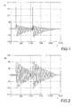
- Figure 1 shows an example of the sum current I 0 of a faulty feeder related to a restriking earth fault in a network earthed with a Petersen coil.
- the current peaks shown are associated with breakdowns. Decreasing oscillation the frequency of which is close to the basic frequency and which follows the peaks represents the capacitive current related to the zero voltage U 0 .
- Figure 2 illustrates an example of the zero voltage U 0 related to a restriking earth fault in a network earthed with a Petersen coil. The amplitude of the zero voltage U 0 increases momentarily always when a breakdown occurs and decreases thereafter.
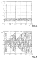
- Figure 3 shows an example of the current I v of a faulty phase related to a restriking earth fault in a network earthed with a Petersen coil.
- the current peaks shown are associated with breakdowns.
- Figure 4 illustrates an example of the voltage U v of a faulty phase related to a restriking earth fault in a network earthed with a Petersen coil. The amplitude of the phase voltage U v decreases when a breakdown occurs and increases thereafter.
- Figure 5 is an enlarged view of superimposed curve forms of Figures 3 and 4 around the first current peak.
- the polarity of the current peak in a faulty phase is the same as the polarity of the phase voltage at that moment.
- the zero voltage is the sum of phase voltages, i.e. the voltage between the star point of the network and the earth or a variable derived therefrom.
- the zero voltage is substantially constant regardless of where it is measured in the network.
- the polarity of a current pulse is positive when it moves from the busbar to the feeder F1 or F2.
- the zero current or the sum current refers to the sum of the phase currents or to a variable derived therefrom at a certain point of the network.
- the sum current of the feeder or line F1 or F2 means the sum current of the feeder F1 or F2 phases L1, L2 and L3 passing near the access point of the feeder F1 or F2 and the busbar system, or a variable derived therefrom.
- the basic idea of the inventive solution is that current peaks related to a restriking earth fault are utilized for identifying a fault and determining its direction.
- One way is to compare the polarities of the current peaks (or current pulses) with each other or with the sign of the instantaneous value of the voltage in the faulty phase L3.
- Utilization of the voltage of the faulty phase L3 is based on the fact that on the faulty feeder F2 the polarity of the current peak related to the breakdown is the same as the polarity of the instantaneous value of the voltage in the faulty phase L3 at the moment of the breakdown.
- the reference voltage in question is the same as on the faulty feeder F2 but the polarity of the current peak is of the opposite sign; the current pulse moving towards the fault location a on the faulty feeder F2 passes through the earth capacitance C 11 , C 12 and C 13 of the healthy feeders F1.
- Another way is to compare the current pulses with each other.
- the comparison can be made between different phases of the same feeder or between different feeders.
- the polarity of the current pulse of the faulty phase L3 on the faulty feeder F2 is opposite to the polarity of the current pulses of the healthy phases L1 and L2.
- the current pulse of the faulty phase L3 is also higher than those of the healthy phases L1 and L2.
- the current pulses of the healthy phases L1 and L2 may be so low that they cannot be distinguished from the normal load current.
- the current pulse is usually higher than the normal load current.
- protection may be based on the following criterion: if a current peak is detected in one phase which is higher than the current peaks in the other phases, the line in question is faulty.
- the protective relay (not shown) according to the inventive solution trips or gives an alarm when at least a predetermined number of current peaks exceeding a predetermined limit in a predetermined time indicate that the fault is ahead. Because of measurement errors and interference in measurement circuits, it is advantageous to subtract the counter of current peaks if a current peak indicates that there is a fault behind.
- the reset time of the earth fault relays on the feeders F1 and F2 should not be too long, either, so that peaks caused in the current signal by interference in the measuring circuits and switching phenomena, for example, do not cause undue trippings.
- the activation and reset of the earth fault relays and fault detectors (not shown) on the feeder F1 or F2 are based on the zero voltage: if sufficiently many current pulses have a polarity indicating a fault on the feeder F1 or F2 and the zero voltage is high enough, the device will be activated and remain activated until the zero voltage exceeds the set limit. This way it is possible to prevent reset in a situation where the interval between breakdowns is long.
- the risk of unselective function of the zero voltage relay serving as back-up protection and the zero current relay of the feed T decreases when the earth-fault protection of the faulty feeder F2 is kept activated on the basis of the same criterion as the back-up protection. Thus it will not happen that the relay of the faulty feeder F2 resets between the current peaks, while the back-up protection of the station S does not, which would lead to unselective operation of the back-up protection.
- the dispersion in the operating times of the protective relays on the feeders F1 and F2 may be larger than in conventional earth faults, regardless of the criterion for activation and reset. If conventional back-up protection based on the zero voltage relay or zero current relay is used, increase in the dispersion of the operating times of the main protection has to be taken into account by increasing the operating time of the back-up protection. However, this weakens the personnel safety.
- the back-up protection finds out either independently by means of the properties of the zero voltage or zero current or on the basis of the messages sent by the earth fault relays of the feeders F1 and F2 that the situation in question is a restriking earth fault and resets between the current peaks.
- the solution of the invention allows to distinguish between a restriking earth fault and an ordinary earth fault.
- the relay may operate differently in various situations and make e.g. reclosings in restriking earth faults.
- the relay may only inform the operator of a restriking earth fault, and consequently the operator may try to release the line again if it is not desirable to replace the faulty cable at this point.
- the fault detector utilizing the same method of the invention correspondingly informs the operator of whether the situation in question is a conventional or a restriking earth fault.
- a restriking earth fault can be distinguished from a conventional earth fault by identifying current pulses or on the basis of the properties of the zero voltage, for example.
- the current peaks related to a restriking earth fault may be very short.
- Application of the inventive method requires that the device used should be capable of measuring the phenomena described, i.e. it must have a sufficiently high sampling frequency.
- the solution of the invention enables location of a restriking earth fault on the feeder F1 and F2 by placing fault detection devices (not shown) capable of determining the direction of a fault along the feeder F1 and F2.
- fault detection devices (not shown) capable of determining the direction of a fault along the feeder F1 and F2.
- These devices employ one of the inventive methods, which may be the same as the method used in the protective relays at the beginning of the feeder F1 and F2.
- the fault detector indicates that there is a restriking earth fault ahead and the following fault detector does not indicate anything or indicates that there is a fault behind
- the fault is located on the feeder F1 and F2 between the fault detectors, and it can be located more accurately by other methods.
- communication connections are needed between the detectors and the substation S or the control room (not shown) so that the measurements of the fault detectors could be utilized.
- the polarity of the current peak related to the restriking earth fault is compared with the sign of the instantaneous value of the voltage in phase L3.
- a typical way of identifying the faulty feeder F2 is to first identify the faulty phase L3 and then to compare the polarity of the current pulse passing the faulty phase L3 with the instantaneous value of the voltage in the faulty phase L3 at the moment of the breakdown.
- the faulty phase L3 can be identified e.g. by comparing the instantaneous values of the phase currents with their effective values or with basic frequency components.
- this value of the current is interpreted as its peak value. If the peak value of the current in one phase L1, L2 or L3 exceeds the peak value of the other phases, the phase in question is interpreted as faulty.
- Another way is to identify the faulty phase L3 on the basis of the voltage magnitude.
- the voltage of the faulty phase L3 drops at the moment of the breakdown significantly lower than normal, whereas the voltages of the healthy phases L1 and L2 increase significantly higher than normal.
- the polarity of the current pulse can be compared with the direction of the momentary change in the zero voltage.
- zero current pulses can be monitored instead of the current pulse of the faulty phase L3 because they both occur at the same moment and have the same polarity.
- the zero current pulses can also be generated in different ways: e.g. by a cable current transformer arranged around each phase conductor, sum connection of phase-specific current transformers or by digital summing of phase current signals.
- Another alternative is to compare the polarities of the current peaks of different phases L1, L2 and L3, provided that each phase contains a measurable current peak. If the polarity of the highest current peak is opposite to the polarity of the current peaks of the two other phases, the feeder in question is faulty.
- the criterion for determining the direction on the basis of the magnitude of phase current peak values can be complemented with identification of the faulty phase L3 on the basis of voltage measurements. In that case the fault is interpreted as being ahead only if the current peaks are the highest in the phase L1, L2 or L3 which has been determined to be faulty on the basis of the voltage measurements.
- the devices e.g. protective relays
- the devices e.g. protective relays
- the polarity of the current pulses related to a restriking earth fault on the faulty feeder F2 is always opposite to the polarity of the current pulses of the healthy feeders F1.
- the currents of several different feeders F1 and F2 can also be measured by one device only by connecting the current transformers or current sensors of the different feeders to it.
- the method also comprises a step in which the current pulse of the faulty feeder F2 or of the faulty phase L3 is compared to a predetermined threshold value, and the relay trips or gives an alarm if a predetermined number of current peaks exceeding the limit within a predetermined period indicate that the fault is in the protected area.
- An appropriate reset criterion for the zero voltage relay and the zero current relay is, for example, exponential decrease of the amplitude of the zero voltage or zero current between breakdowns (decrease of the zero voltage U 0 is seen in Figure 2).
- the relay may reset, for example, if the quotient of two successive maximum values is nearly the same and less than one for a set time, i.e. for sufficiently many periods.
- Exponential decrease of the zero voltage and zero current can be recognized in various other ways, e.g. by calculating the amplitude by a prior art digital filter and by adjusting the amplitude curve to the exponential function using a prior art curve adjustment method, such as the method of least square.
- the protective relay which serves as back-up protection and measures the zero voltage or the zero current of the feed T resets and does not trip.
- the other alternative criterion is based on the fact that the frequency of the decreasing zero voltage and zero current often differs from the nominal frequency of the network (e.g. 50 or 60 Hz).
- This frequency usually differs sufficiently from the nominal frequency (in practice a few hertz) so that the frequency information can be used as the reset criterion.
- the frequency can be measured by a known frequency estimation method, for example.
- the reset criterion may also be based on the fact that the frequency differs from the nominal frequency of the network.
- a feeder-specific device may transmit information on a restriking earth fault detected by it to the back-up protection and prevent unwanted operation thereof.
- a restriking earth fault can be distinguished from a conventional earth fault e.g. by comparing the instantaneous values of the phase currents with the effective values of these phase currents or with basic frequency components.
- Another alternative is to utilize the properties of the zero voltage or zero current as was described above in connection with the reset criteria for the zero voltage relay and zero current relay of the feed.
- the most preferred way of identifying a restriking earth fault and a faulty feeder F2 by means of current peaks and voltage measurements is to first identify the faulty phase L3 and then to compare the polarity of the current pulse passing the faulty phase L3 with the instantaneous value of the voltage in the faulty phase L3 when the breakdown occurs.
- This method is the most reliable one because it is based on the fact that the polarity of the current pulse moving towards the breakdown point is unmistakably dependent on the voltage polarity at the moment of the breakdown. Consequently, if the current pulse and voltage measured at the beginning of the feeder F1 or F2 have the same polarity, the restriking earth fault is undoubtedly on the feeder in question. If the polarities differ from each other, the feeder F1 or F2 in question is healthy and only feeds a restriking earth fault which exists on some other feeder F1 or F2.
- the magnitudes of the phase voltages for identifying the faulty phase L3.
- the maximum instantaneous value of the current at the moment the phase voltage decreases is chosen as the peak value of the current. To improve reliability, it may be checked that the current peak value found exceeds the effective value of the current or the basic frequency component by a predetermined amount.
- the second most preferred way of utilizing the current peaks and voltage measurements is to compare the polarity of a current peak with the momentary change in the zero voltage when the current pulse is generated.
- This method has as solid a physical basis as the above-mentioned method based on the phase voltage.
- the zero voltage increases at the same moment as the breakdown occurs. If the polarity of the current pulse measured at the beginning of the feeder F1 or F2 is opposite to the polarity of the momentary change in the zero voltage, the restriking earth fault is undoubtedly on the feeder in question.
- the problem of this method is that sometimes the sudden change in the zero voltage at the moment of the breakdown is small compared to the absolute value of the zero voltage at the given moment. This is especially the case if the zero voltage decreases slowly between the breakdowns. Thus it may be difficult to determine the direction of change in the zero voltage reliably, especially if the environment interferes with the measuring circuits.
- the most preferred alternative is to compare only the magnitudes of the current peaks. This method is the best because it can also be used when the fault is on a short feeder, in which case the current peaks of the healthy feeders may be too small to be measurable.
- a disadvantage of this method is that interference to the measuring circuits may cause a current peak resembling a fault in one phase L1, L2 or L3 and result in unwanted tripping.
- the feeders F1 and F2 are so long that the restriking earth fault also causes sufficiently high current peaks in the healthy phases, it is preferable to compare the polarity of the highest phase current peak with the polarities of the simultaneous current peaks of the other phases. In that case the probability that the interference peaks in the measuring circuits cause unwanted tripping is very small, because this would require simultaneous interference peaks of the opposite polarity in the measuring circuits of the other phases.
- the faulty feeder F2 can be determined in a very simple and reliable manner.
- the feeder the current pulse of which has a different polarity than those of the other feeders is faulty.
- This principle is the most preferred one also because any interference pulses in the current measuring circuit of one relay do not cause unwanted tripping since the method requires that the current pulses pass simultaneously on several feeders F1 and F2.
- the same device directly measures the currents of various feeders F1 and F2 and thus identifies the faulty feeder on the basis of the polarities of the current pulses of the different feeders.
- An advantage of this solution is that there is no need for communication between the devices measuring the currents of the different feeders F1 and F2, nor between these devices and another central device or host device.
- cables are needed to transmit analog measuring information between the current transformers or current sensors of the different feeders F1 and F2 and the device comparing the currents.
- the zero voltage relay or zero current relay serving as back-up protection it is preferable to combine different methods.
- it is recommendable to make the activation of the earth-fault protections of the feeders F1 and F2 dependent on the existing zero voltage so that, having been activated, the protective relay of the faulty feeder F2 does not reset until the zero voltage decreases below a certain limit. This allows to prevent a situation in which the protective relay of the faulty feeder F2 is alternately activated and reset but it never trips.
- the zero voltage relay serving as back-up protection or the zero current relay of the feed T resets and does not trip having detected properties related to a restriking earth fault in the zero voltage or zero current. If a communication connection is used, one of the earth fault relays of the feeders F1 or F2 preferably clamps the back-up protection after it has detected a restriking earth fault.
Landscapes
- Locating Faults (AREA)
- Testing Of Short-Circuits, Discontinuities, Leakage, Or Incorrect Line Connections (AREA)
- Emergency Protection Circuit Devices (AREA)
Abstract
Description
Claims (36)
- A protection method of an electricity network against restriking earth faults, which electricity network comprises one or more feeders going out from a supply point and is preferably a three-phase network, the method comprising the steps of:detecting an earth contact related to an earth fault in the electricity network,identifying the feeder on which the earth contact occurs by means of current pulses or current pulses and voltage values related to the earth contact, a current value being interpreted as a current pulse at the moment the instantaneous value of the current divided by the effective value of the current exceeds a predetermined limit, characterized bycalculating the number of detected earth contacts per each feeder, andidentifying that there is a restriking earth fault on the feeder if the number of the detected earth contacts per said feeder exceeds a predetermined number during a predetermined period, or if the number of the detected earth contacts per said feeder exceeds a predetermined number while the voltage between the star point of the electricity network and the earth, i.e. the zero voltage, remains above a predetermined limit.
- A method according to claim 1, characterized in that one is subtracted from the number of the earth contacts detected on a feeder if the number is greater than zero and if an earth contact is detected on another feeder.
- A method according to claim 1 or 2, characterized in that the step for identifying the feeder on which the earth contact occurs comprises the steps of:identifying the faulty phase,comparing, feeder specifically, the polarity of the pulse caused by the earth contact of the current in the faulty phase, of the sum current of the phases or of a variable which is in a known phase shift with said currents with the polarity of the instantaneous value of the voltage in the faulty phase or with the polarity of a variable which is in a known phase shift with said voltage at the moment of the earth fault, andidentifying the feeder as faulty if the polarity of the current in the faulty phase or that of the sum current of the phases is the same as the polarity of the instantaneous value of the voltage in the faulty phase.
- A method according to claim 1 or 2, characterized in that the step for identifying the feeder on which the earth contact occurs comprises the steps of:identifying the faulty phase,comparing, feeder specifically, the polarity of the pulse caused by the earth contact of he current in the faulty phase or of a variable which is in a known phase shift with said current with the polarity of the momentary change in the zero voltage of the network or in a variable which is in a known phase shift with said zero voltage at the moment of the earth fault, andidentifying the feeder as faulty if the polarity of the current in the faulty phase is opposite to the polarity of momentary change in the zero voltage of the network.
- A method according to claim 1 or 2, characterized in that the step for identifying the feeder on which the earth contact occurs comprises the steps of:comparing, feeder specifically, the polarity of the pulse caused by the earth contact of the sum current of the phases or of a variable which is in a known phase shift with said sum current with the polarity of the momentary change in the zero voltage of the network or in a variable which is in a known phase shift with said zero voltage at the moment of the earth fault, andidentifying the feeder as faulty if the polarity of the sum current of the phases is opposite to the polarity of momentary change in the zero voltage of the network.
- A method according to claim 1 or 2, characterized in that the step for identifying the feeder on which the earth contact occurs comprises the steps of:monitoring, feeder specifically, the magnitudes of the pulses caused by the earth contact of the phase currents or of variables which are in a known relation to said currents, andcomparing, feeder specifically, the magnitudes of the pulses caused by the earth contact of the phase currents or of variables which are in a known relation to said currents with each other, andidentifying the feeder as faulty if the current pulse of a feeder phase is higher than a predetermined limit and higher than in the other feeder phases.
- A method according to claim 1 or 2, characterized in that the step for identifying the feeder on which the earth contact occurs comprises the steps of:monitoring, feeder specifically, the magnitudes of the pulses caused by the earth contact of the phase currents or of variables which are in a known relation to said currents,comparing, feeder specifically, the magnitudes and polarities of the pulses caused by the earth contact of the phase currents or of variables which are in a known relation to said currents with each other, andidentifying the feeder as faulty if the current pulse of a feeder phase is higher than a predetermined limit, higher than in the other feeder phases and has a polarity opposite to the polarities of the current pulses in the other feeder phases.
- A method according to claim 1 or 2, characterized in that the step for identifying the feeder on which the earth contact occurs comprises the steps of:monitoring, feeder specifically, the magnitudes of the pulses caused by the earth contact of the phase currents or of variables which are in a known relation to said currents,comparing, feeder specifically, the magnitudes of the pulses caused by the earth contact of the phase currents or of variables which are in a known relation to said currents with each other, and the magnitudes of the phase voltages or the magnitudes of variables which are in a known relation to said voltages with each other, andidentifying the feeder as faulty if the current pulse of a feeder phase is higher than a predetermined limit, higher than in the other feeder phases and if the voltage of said phase is also smaller than the voltage of the other phases.
- A method according to claim 1 or 2, characterized in that the step for identifying the feeder on which the earth contact occurs comprises the steps of:comparing the polarities of the pulses caused by the earth contact of the sum currents of the feeder phases or of variables which are in a known phase shift with said sum currents with each other, andidentifying the feeder as faulty if the polarity of the sum current on the feeder is opposite to the polarities of the sum currents on the other feeders.
- A method according to claim 1 or 2, characterized in that the step for identifying the feeder on which the earth contact occurs comprises the steps of:comparing the magnitudes of the pulses caused by the earth contact of the sum currents of the feeder phases or of variables which are in a known relation to said sum currents with each other, andidentifying the feeder as faulty if the sum current pulse on the feeder is higher than on the other feeders.
- A method according to any one of claims 1 to 10, characterized in that if a back-up earth-fault protection, such as a zero voltage relay or a zero current relay, is used in the electricity network, operation of the back-up earth-fault protection is prevented if a predetermined number of earth contacts are detected in the electricity network within a predetermined period.
- A method according to any one of claims 1 to 10, characterized in that if a back-up earth-fault protection, such as a zero voltage relay or a zero current relay, is used in the electricity network, operation of the back-up earth-fault protection is prevented if the amplitude of the zero voltage in the electricity network or that of the zero current at the supply point decreases substantially exponentially.
- A method according to any one of claims 1 to 10, characterized in that if a back-up earth-fault protection, such as a zero voltage relay or a zero current relay, is used in the electricity network, operation of the back-up earth-fault protection is prevented if the frequency of the zero voltage in the electricity network or that of the zero current at the supply point differs essentially from the nominal frequency of the electricity network.
- A method according to any one of claims 1 to 13, characterized in that reclosings can be made to eliminate a certain earth fault only if the earth fault is identified as a restriking earth fault.
- A system for protecting an electricity network against restriking earth faults, which electricity network comprises one or more feeders (F1 and F2) going out from a supply point (S) and is preferably a three-phase (L1, L2 and L3) network, the system being arranged to:detect an earth contact related to an earth fault in the electricity network,identify the feeder (F2) on which the earth contact occurs by means of current pulses or current pulses and voltage values related to the earth contact, a current value being interpreted as a current pulse at the moment the instantaneous value of the current divided by the effective value of the current exceeds a predetermined limit, characterized in that the system is also arranged to:calculate the number of detected earth contacts per each feeder (F1 and F2), andidentify that there is a restriking earth fault on the feeder (F1 or F2) if the number of the detected earth contacts per said feeder (F1 or F2) exceeds a predetermined number during a predetermined period, or if the number of the detected earth contacts per said feeder (F1 or F2) exceeds a predetermined number while the voltage between the star point of the electricity network and the earth, i.e. the zero voltage, remains above a predetermined limit.
- A system according to claim 15, characterized in that the system is arranged to subtract one from the number of the earth contacts detected on a feeder (F1 or F2) if the number is greater than zero and if an earth contact is detected on another feeder (F1 or F2).
- A system according to claim 15 or 16, characterized in that on identifying the feeder (F2) on which the earth contact occurs the system is arranged to:identify the faulty phase (L3),compare, feeder (F1 and F2) specifically, the polarity of the pulse caused by the earth contact of the current in the faulty phase (L3), of the sum current of the phases (L1, L2 and L3) or of a variable which is in a known phase shift with said currents with the polarity of the instantaneous value of the voltage in the faulty phase (L3) or with the polarity of a variable which is in a known phase shift with said voltage at the moment of the earth fault, andidentify (F1 or F2) the feeder as faulty if the polarity of the current in the faulty phase (L3) or that of the sum current of the phases (L1, L2 and L3) is the same as the polarity of the instantaneous value of the voltage in the faulty phase.
- A system according to claim 15 or 16, characterized in that on identifying the feeder (F2) on which the earth contact occurs the system is arranged to:identify the faulty phase (L3),compare, feeder (F1 and F2) specifically, the polarity of the pulse caused by the earth contact of the current in the faulty phase (L3) or of a variable which is in a known phase shift with said current with the polarity of the momentary change in the zero voltage of the network or in a variable which is in a known phase shift with said zero voltage at the moment of the earth fault, andidentify the feeder (F1 or F2) as faulty if the polarity of the current in the faulty phase (L3) is opposite to the polarity of the momentary change in the zero voltage of the network.
- A system according to claim 15 or 16, characterized in that on identifying the feeder (F2) on which the earth contact occurs the system is arranged to:compare, feeder (F1 and F2) specifically, the polarity of the pulse caused by the earth contact of the sum current of the phases (L1, L2 and L3) or of a variable which is in a known phase shift with said sum current with the polarity of the momentary change in the zero voltage of the network or in a variable which is in a known phase shift with said zero voltage at the moment of the earth fault, andidentify the feeder (F1 or F2) as faulty if the polarity of the sum current of the phases (L1, L2 and L3) is opposite to the polarity of momentary change in the zero voltage of the network.
- A system according to claim 15 or 16, characterized in that on identifying the feeder (F2) on which the earth contact occurs the system is arranged to:monitor, feeder (F1 and F2) specifically, the magnitudes of the pulses caused by the earth contact of the phase (L1, L2 and L3) currents or of variables which are in a known relation to said currents, andcompare, feeder (F1 and F2) specifically, the magnitudes of the pulses caused by the earth contact of the phase (L1, L2 and L3) currents or of variables which are in a known relation to said currents with each other, andidentify the feeder (F1 or F2) as faulty if the current pulse in a feeder phase (L1, L2 or L3) is higher than a predetermined limit and higher than in the other feeder phases (L1, L2 or L3).
- A system according to claim 15 or 16, characterized in that on identifying the feeder (F2) on which the earth contact occurs the system is arranged to:monitor, feeder (F1 and F2) specifically, the magnitudes of the pulses caused by the earth contact of the phase (L1, L2 and L3) currents or of variables which are in a known relation to said currents,compare, feeder (F1 and F2) specifically, the magnitudes and polarities of the pulses caused by the earth contact of the phase (L1, L2 and L3) currents or of variables which are in a known relation to said currents with each other, andidentify the feeder (F1 or F2) as faulty if the current pulse in a feeder phase (L1, L2 or L3) is higher than a predetermined limit, higher than in the other feeder phases (L1, L2 or L3) and has a polarity opposite to the polarities of the current pulses in the other feeder phases.
- A system according to claim 15 or 16, characterized in that on identifying the feeder (F2) on which the earth contact occurs the system is arranged to:monitor, feeder (F1 and F2) specifically, the magnitudes of the pulses caused by the earth contact of the phase (L1, L2 and L3) currents or of variables which are in a known relation to said currents,compare, feeder (F1 and F2) specifically, the magnitudes of the pulses caused by the earth contact of the phase (L1, L2 and L3) currents or of variables which are in a known relation to said currents with each other, and the magnitudes of the phase voltages or the magnitudes of variables which are in a known relation to said voltages with each other, andidentify the feeder (F1 or F2) as faulty if the current pulse in a feeder phase (L1, I2 or L3) is higher than a predetermined limit, higher than in the other feeder phases and if the voltage of said phase is also smaller than the voltage in the other phases.
- A system according to claim 15 or 16, characterized in that on identifying the feeder (F2) on which the earth contact occurs the system is arranged to:compare the polarities of the pulses caused by the earth contact of the sum currents of the feeder (F1 and F2) phases (L1, L2 and L3) or of variables which are in a known phase shift with said sum currents with each other, andidentify the feeder (F1 or F2) as faulty if the polarity of the sum current on the feeder is opposite to the polarities of the sum currents on the other feeders.
- A system according to claim 15 or 16, characterized in that on identifying the feeder (F2) on which the earth contact occurs the system is arranged to:compare the magnitudes of the pulses caused by the earth contact of the sum currents of the feeder (F1 and F2) phases (L1, L2 and L3) or of variables which are in a known relation to said sum currents with each other, andidentify the feeder (F1 or F2) as faulty if the sum current pulse on the feeder is higher than on the other feeders.
- A system according to any one of claims 15 to 24, characterized in that if the electricity network comprises a back-up earth-fault protection, such as a zero voltage relay or a zero current relay, the system is arranged to prevent operation of the back-up earth-fault protection if at least a predetermined number of earth contacts is detected in the electricity network within a predetermined period.
- A system according to any one of claims 15 to 24, characterized in that if the electricity network comprises a back-up earth-fault protection, such as a zero voltage relay or a zero current relay, the system is arranged to prevent operation of the back-up earth-fault protection if the amplitude of the zero voltage in the electricity network or that of the zero current at the supply point (S) decreases substantially exponentially.
- A system according to any one of claims 15 to 24, characterized in that if the electricity network comprises a back-up earth-fault protection, such as a zero voltage relay or a zero current relay, the system is arranged to prevent operation of the back-up earth-fault protection if the frequency of the zero voltage in the electricity network or that of the zero current at the supply point (S) differs substantially from the nominal frequency of the electricity network.
- A system according to any one of claims 15 to 27, characterized in that the system is arranged to allow reclosings to eliminate a certain earth fault only if it identifies that the earth fault is a restriking earth fault.
- A detecting apparatus for indicating the direction of the location of a restriking earth fault in an electricity network which comprises one or more feeders (F1 and F2) going out from a supply point (S) and is preferably a three-phase (L1, L2 and L3) network, the detection apparatus being located at some point of the electricity network and arranged to:detect an earth contact related to an earth fault in the electricity network,identify, by means of current pulses or current pulses and voltage values related to the earth contact, whether the earth contact occurs in the direction of the supply point (S) of the electricity network, i.e. in the upstream direction, with respect to the apparatus or in the other direction, i.e. in the downstream direction, a current value being interpreted as a current pulse at the moment the instantaneous value of the current divided by the effective value of the current exceeds a predetermined limit, characterized in that the apparatus is also arranged tocalculate the number of detected earth contacts per both said directions, andindicate that there is a restriking earth fault in a certain direction if the number of the detected earth contacts per said direction exceeds a predetermined number within a predetermined period, or if the number of the detected earth faults per said direction exceeds a predetermined number while the voltage between the star point of the electricity network and the earth, i.e. the zero voltage, remains above a predetermined limit.
- An apparatus according to claim 29, characterized in that the apparatus is arranged to subtract one from the number of the earth contacts detected in a certain direction if the number is greater than zero and if an earth contact is detected in the other direction.
- An apparatus according to claim 29 or 30, characterized in that on identifying the direction in which the earth contact occurs the apparatus is arranged to:identify the faulty phase (L3),compare the polarity of the pulse caused by the earth contact of the current in the faulty phase (L3), of the sum current of the phases (L1, L2 and L3) or of a variable which is in a known phase shift with said currents with the polarity of the instantaneous value of the voltage in the faulty phase (L3) or with the polarity of a variable which is in a known phase shift with said voltage at the moment of the earth fault, andidentify that the fault is in the downstream direction from the apparatus if the polarity of the current in the faulty phase (L3) or that of the sum current of the phases is the same as the polarity of the instantaneous value of the voltage in the faulty phase, and that otherwise the fault is in the upstream direction from the apparatus.
- A apparatus according to claim 29 or 30, characterized in that on identifying the direction in which the earth contact occurs the apparatus is arranged to:identify the faulty phase (L3),compare the polarity of the pulse caused by the earth contact of the current in the faulty phase (L3) or of a variable which is in a known phase shift with said current with the polarity of the momentary change in the zero voltage of the network or in a variable which is in a known phase shift with said zero voltage at the moment of the earth fault, andidentify that the fault is in the downstream direction from the apparatus if the polarity of the current in the faulty phase (L3) is opposite to the polarity of the momentary change in the zero voltage of the network, and that otherwise the fault is in the upstream direction from the apparatus.
- An apparatus according to claim 29 or 30, characterized in that on identifying the direction in which the earth contact occurs the apparatus is arranged to:compare the polarity of the pulse caused by the earth contact of the sum current of the phases (L1, L2 and L3) or of a variable which is in a known phase shift with said sum current with the polarity of the momentary change in the zero voltage of the network or in a variable which is in a known phase shift with said zero voltage at the moment of the earth fault, andidentify that the fault is in the downstream direction from the apparatus if the polarity of the sum current of the phases (L1, L2 and L3) is opposite to the polarity of the momentary change in the zero voltage of the network, and that otherwise the fault is in the upstream direction from the apparatus.
- An apparatus according to claim 29 or 30, characterized in that on identifying the direction in which the earth contact occurs the apparatus is arranged to:monitor the magnitudes of the pulses caused by the earth contact of the phase (L1, L2 and L3) currents or of variables which are in a known relation to said currents, andcompare the magnitudes of the pulses caused by the earth contact of the phase (L1, L2 and L3) currents or of variables which are in a known relation to said currents with each other, andidentify that the fault is in the downstream direction from the apparatus if the current pulse in a phase (L1, L2 or L3) is higher than a predetermined limit and higher than in the other phases, and that otherwise the fault is in the upstream direction from the apparatus.
- A apparatus according to claim 29 or 30, characterized in that on identifying the direction in which the earth contact occurs the apparatus is arranged to:monitor the magnitudes of the pulses caused by earth contact of the phase (L1, L2 and L3) currents or of variables which are in a known relation to said currents,compare the magnitudes and polarities of the pulses caused by the earth contact of the phase (L1, L2 and L3) currents or of variables which are in a known relation to said currents with each other, andidentify that the fault is in the downstream direction from the apparatus if the current pulse in a phase (L1, L2 or L3) is higher than a predetermined limit, higher than in the other phases and has a polarity opposite to the polarities of the current pulses in the other phases, and that otherwise the fault is in the upstream direction from the apparatus.
- An apparatus according to claim 29 or 30, characterized in that on identifying the direction in which the earth contact occurs the apparatus is arranged to:monitor the magnitudes of the pulses caused by the earth contact of the phase (L1, L2 and L3) currents or of variables which are in a known relation to said currents,compare the magnitudes of the pulses caused by the earth contact of the phase (L1, L2 and L3) currents or of variables which are in a known relation to said currents with each other, and the magnitudes of the phase voltages or the magnitudes of variables which are in a known relation to said voltages with each other, andidentify that the fault is in the downstream direction from the apparatus if the current pulse in a phase (L1, L2 or L3) is higher than a predetermined limit, higher than in the other phases and if the voltage of said phase is also smaller than the voltage in the other phases, and that otherwise the fault is in the upstream direction from the apparatus.
Applications Claiming Priority (2)
| Application Number | Priority Date | Filing Date | Title |
|---|---|---|---|
| FI982375A FI117258B (en) | 1998-11-02 | 1998-11-02 | Earth insulation cover for an electrical grid |
| FI982375 | 1998-11-02 |
Publications (3)
| Publication Number | Publication Date |
|---|---|
| EP0999633A2 true EP0999633A2 (en) | 2000-05-10 |
| EP0999633A3 EP0999633A3 (en) | 2001-04-18 |
| EP0999633B1 EP0999633B1 (en) | 2010-01-20 |
Family
ID=8552832
Family Applications (1)
| Application Number | Title | Priority Date | Filing Date |
|---|---|---|---|
| EP99660172A Expired - Lifetime EP0999633B1 (en) | 1998-11-02 | 1999-11-01 | Earth-fault protection for electricity network |
Country Status (3)
| Country | Link |
|---|---|
| EP (1) | EP0999633B1 (en) |
| DE (1) | DE69941943D1 (en) |
| FI (1) | FI117258B (en) |
Cited By (11)
| Publication number | Priority date | Publication date | Assignee | Title |
|---|---|---|---|---|
| DE10302451B3 (en) * | 2003-01-22 | 2004-07-15 | Edc Gmbh | Earthing connection recognition method for 3-phase network using evaluation of charge curve obtained by integration of current from voltage zero transition and zero voltage limit value point |
| EP1526621A1 (en) * | 2003-10-22 | 2005-04-27 | Trench Austria GmbH | Method for identifying intermittent ground faults |
| AT500195B1 (en) * | 2002-06-06 | 2007-10-15 | Edc Gmbh | Selective transient earth fault detection in polyphase networks involves comparing displacement voltage and null current curves, evaluating proportionality factor to detect earth leakage and direction |
| FR2902887A1 (en) * | 2006-06-23 | 2007-12-28 | Schneider Electric Ind Sas | Downstream ground defect directional detection method for three phase medium voltage electrical distribution network, involves signaling downstream ground defect based on signals representing phase currents |
| WO2010115474A1 (en) * | 2009-04-10 | 2010-10-14 | Areva T&D Uk Ltd | Method and system for transient and intermittent earth fault detection and direction determination in a three-phase median voltage electric power distribution system |
| WO2012171694A1 (en) | 2011-06-14 | 2012-12-20 | Dlaboratory Sweden Ab | A method for detecting earth faults |
| CN107735690A (en) * | 2015-06-03 | 2018-02-23 | 于韦斯屈莱能源有限公司 | The method of the earth-fault protection of three-phase electrical network |
| AT519573B1 (en) * | 2017-04-25 | 2018-08-15 | Siemens Ag | Method for the identification of a fault of a three-phase network, which is subject to a ground fault |
| CN114384367A (en) * | 2021-10-28 | 2022-04-22 | 成都交大许继电气有限责任公司 | Traction network based on 50% standby of circuit breaker, fault location method and connection method |
| CN115856406A (en) * | 2022-06-22 | 2023-03-28 | 国网湖南省电力有限公司 | Intelligent control method and system for bus capacitance current of transformer substation |
| CN118688579A (en) * | 2024-08-27 | 2024-09-24 | 国网山东省电力公司济南供电公司 | A ground fault line identification method, system, device and storage medium |
Family Cites Families (2)
| Publication number | Priority date | Publication date | Assignee | Title |
|---|---|---|---|---|
| JPH06300807A (en) * | 1993-04-15 | 1994-10-28 | Hitachi Ltd | Insulation deterioration detector |
| US5488532A (en) * | 1993-10-27 | 1996-01-30 | Sundstrand Corporation | System of protection for electric power distribution failures |
-
1998
- 1998-11-02 FI FI982375A patent/FI117258B/en not_active IP Right Cessation
-
1999
- 1999-11-01 EP EP99660172A patent/EP0999633B1/en not_active Expired - Lifetime
- 1999-11-01 DE DE69941943T patent/DE69941943D1/en not_active Expired - Lifetime
Cited By (16)
| Publication number | Priority date | Publication date | Assignee | Title |
|---|---|---|---|---|
| AT500195B1 (en) * | 2002-06-06 | 2007-10-15 | Edc Gmbh | Selective transient earth fault detection in polyphase networks involves comparing displacement voltage and null current curves, evaluating proportionality factor to detect earth leakage and direction |
| DE10302451B3 (en) * | 2003-01-22 | 2004-07-15 | Edc Gmbh | Earthing connection recognition method for 3-phase network using evaluation of charge curve obtained by integration of current from voltage zero transition and zero voltage limit value point |
| EP1526621A1 (en) * | 2003-10-22 | 2005-04-27 | Trench Austria GmbH | Method for identifying intermittent ground faults |
| FR2902887A1 (en) * | 2006-06-23 | 2007-12-28 | Schneider Electric Ind Sas | Downstream ground defect directional detection method for three phase medium voltage electrical distribution network, involves signaling downstream ground defect based on signals representing phase currents |
| EP1890165A3 (en) * | 2006-06-23 | 2011-03-09 | Schneider Electric Industries SAS | Method of directional detection of a fault in the ground connection and device for implementing same |
| WO2010115474A1 (en) * | 2009-04-10 | 2010-10-14 | Areva T&D Uk Ltd | Method and system for transient and intermittent earth fault detection and direction determination in a three-phase median voltage electric power distribution system |
| CN101858948B (en) * | 2009-04-10 | 2015-01-28 | 阿海珐输配电英国有限公司 | Method and system for carrying out transient and intermittent earth fault detection and direction determination in three-phase medium-voltage distribution system |
| WO2012171694A1 (en) | 2011-06-14 | 2012-12-20 | Dlaboratory Sweden Ab | A method for detecting earth faults |
| CN107735690A (en) * | 2015-06-03 | 2018-02-23 | 于韦斯屈莱能源有限公司 | The method of the earth-fault protection of three-phase electrical network |
| EP3304105A4 (en) * | 2015-06-03 | 2019-07-10 | ABB Schweiz AG | EARTH FAULT PROTECTION METHOD FOR THREE-PHASE ELECTRICAL NETWORK |
| AT519573B1 (en) * | 2017-04-25 | 2018-08-15 | Siemens Ag | Method for the identification of a fault of a three-phase network, which is subject to a ground fault |
| AT519573A4 (en) * | 2017-04-25 | 2018-08-15 | Siemens Ag | Method for the identification of a fault of a three-phase network, which is subject to a ground fault |
| US11095114B2 (en) | 2017-04-25 | 2021-08-17 | Siemens Energy Global GmbH & Co. KG | Method for identifying an outgoing circuit having an earth fault in a three-phase power supply system |
| CN114384367A (en) * | 2021-10-28 | 2022-04-22 | 成都交大许继电气有限责任公司 | Traction network based on 50% standby of circuit breaker, fault location method and connection method |
| CN115856406A (en) * | 2022-06-22 | 2023-03-28 | 国网湖南省电力有限公司 | Intelligent control method and system for bus capacitance current of transformer substation |
| CN118688579A (en) * | 2024-08-27 | 2024-09-24 | 国网山东省电力公司济南供电公司 | A ground fault line identification method, system, device and storage medium |
Also Published As
| Publication number | Publication date |
|---|---|
| FI117258B (en) | 2006-08-15 |
| EP0999633A3 (en) | 2001-04-18 |
| DE69941943D1 (en) | 2010-03-11 |
| FI982375A0 (en) | 1998-11-02 |
| EP0999633B1 (en) | 2010-01-20 |
| FI982375A7 (en) | 2000-05-03 |
Similar Documents
| Publication | Publication Date | Title |
|---|---|---|
| EP1007986B1 (en) | Fault detection apparatus and method of detecting faults in an electrical distribution network | |
| US8300369B2 (en) | System and method for polyphase ground-fault circuit-interrupters | |
| US7496430B2 (en) | Intelligent fault detector system and method | |
| US5103365A (en) | Downed conductor automatic detecting device | |
| US20180233895A1 (en) | Localized application of high impedance fault isolation in multi-tap electrical power distribution system | |
| US20100013498A1 (en) | System And Method To Determine The Impedance Of A Disconnected Electrical Facility | |
| EP0999633B1 (en) | Earth-fault protection for electricity network | |
| WO2016193529A1 (en) | Method for earth fault protection for a three-phase electrical network | |
| Garcia-Santander et al. | Down-conductor fault detection and location via a voltage based method for radial distribution networks | |
| KR101007551B1 (en) | Arc detection method in power distribution system and arc generation alarm system using the same | |
| US20100202092A1 (en) | Differential Protection Method, System And Device | |
| KR20130031583A (en) | System and method for detecting the high impedence ground fault using distribution automation system | |
| EP1074849A2 (en) | Fault detection in electrical transmission lines | |
| EP0963025A2 (en) | Faulted feeder detection in earth fault in electricity distribution network | |
| US4796147A (en) | Method for detecting voltage losses in a low voltage distribution system | |
| EP1065510B1 (en) | Location of restriking and transient earth faults | |
| CN110212511A (en) | 66kV arc suppression coil earthing system based on resistance strange land automatic switching | |
| EP0905849A1 (en) | Switching device for managing a multi-phase alternating-voltage network having a number of load units | |
| FI108166B (en) | Listing of wiring failures in a power grid | |
| KR101890035B1 (en) | System for protrecting power system and method for operating the same | |
| RU2843341C1 (en) | Method for protection of power transmission line with short circuit taps, detection of short circuit type and section of line, where it occurred | |
| JP2001339847A (en) | Ground directional relay for low voltage circuit | |
| Wishtibeev | Calculation stratey of operate settings protection against ground fault | |
| MXPA01004199A (en) | A protective relay-based monitoring system of dc power within an electric power substation |
Legal Events
| Date | Code | Title | Description |
|---|---|---|---|
| PUAI | Public reference made under article 153(3) epc to a published international application that has entered the european phase |
Free format text: ORIGINAL CODE: 0009012 |
|
| AK | Designated contracting states |
Kind code of ref document: A2 Designated state(s): DE FR GB |
|
| AX | Request for extension of the european patent |
Free format text: AL;LT;LV;MK;RO;SI |
|
| PUAL | Search report despatched |
Free format text: ORIGINAL CODE: 0009013 |
|
| AK | Designated contracting states |
Kind code of ref document: A3 Designated state(s): AT BE CH CY DE DK ES FI FR GB GR IE IT LI LU MC NL PT SE |
|
| AX | Request for extension of the european patent |
Free format text: AL;LT;LV;MK;RO;SI |
|
| 17P | Request for examination filed |
Effective date: 20010615 |
|
| AKX | Designation fees paid |
Free format text: DE FR GB |
|
| 17Q | First examination report despatched |
Effective date: 20080130 |
|
| GRAP | Despatch of communication of intention to grant a patent |
Free format text: ORIGINAL CODE: EPIDOSNIGR1 |
|
| GRAS | Grant fee paid |
Free format text: ORIGINAL CODE: EPIDOSNIGR3 |
|
| GRAA | (expected) grant |
Free format text: ORIGINAL CODE: 0009210 |
|
| AK | Designated contracting states |
Kind code of ref document: B1 Designated state(s): DE FR GB |
|
| REG | Reference to a national code |
Ref country code: GB Ref legal event code: FG4D |
|
| REF | Corresponds to: |
Ref document number: 69941943 Country of ref document: DE Date of ref document: 20100311 Kind code of ref document: P |
|
| PLBE | No opposition filed within time limit |
Free format text: ORIGINAL CODE: 0009261 |
|
| STAA | Information on the status of an ep patent application or granted ep patent |
Free format text: STATUS: NO OPPOSITION FILED WITHIN TIME LIMIT |
|
| 26N | No opposition filed |
Effective date: 20101021 |
|
| REG | Reference to a national code |
Ref country code: FR Ref legal event code: PLFP Year of fee payment: 17 |
|
| REG | Reference to a national code |
Ref country code: FR Ref legal event code: PLFP Year of fee payment: 18 |
|
| REG | Reference to a national code |
Ref country code: FR Ref legal event code: PLFP Year of fee payment: 19 |
|
| REG | Reference to a national code |
Ref country code: GB Ref legal event code: 732E Free format text: REGISTERED BETWEEN 20180308 AND 20180314 |
|
| REG | Reference to a national code |
Ref country code: FR Ref legal event code: TP Owner name: ABB SCHWEIZ AG, CH Effective date: 20180907 |
|
| REG | Reference to a national code |
Ref country code: DE Ref legal event code: R082 Ref document number: 69941943 Country of ref document: DE Representative=s name: DOMPATENT VON KREISLER SELTING WERNER - PARTNE, DE Ref country code: DE Ref legal event code: R081 Ref document number: 69941943 Country of ref document: DE Owner name: ABB SCHWEIZ AG, CH Free format text: FORMER OWNER: ABB OY, HELSINKI, FI |
|
| PGFP | Annual fee paid to national office [announced via postgrant information from national office to epo] |
Ref country code: DE Payment date: 20181120 Year of fee payment: 20 |
|
| PGFP | Annual fee paid to national office [announced via postgrant information from national office to epo] |
Ref country code: GB Payment date: 20181120 Year of fee payment: 20 Ref country code: FR Payment date: 20181123 Year of fee payment: 20 |
|
| REG | Reference to a national code |
Ref country code: DE Ref legal event code: R071 Ref document number: 69941943 Country of ref document: DE |
|
| REG | Reference to a national code |
Ref country code: GB Ref legal event code: PE20 Expiry date: 20191031 |
|
| PG25 | Lapsed in a contracting state [announced via postgrant information from national office to epo] |
Ref country code: GB Free format text: LAPSE BECAUSE OF EXPIRATION OF PROTECTION Effective date: 20191031 |