BACKGROUND OF THE INVENTION
Field of the Invention
The present invention relates to a battery separator
and a manufacturing method thereof, and an alkali secondary
battery having the separator incorporated therein, in
particular to a nickel-metal hydride secondary battery. More
particularly, the present invention relates to a battery
separator and a manufacturing method thereof in which preferred
hydrophilization treatment is applied, and thus, an alkali
secondary battery having the separator incorporated therein
causes its superior self-discharge properties; and a
nickel-metal hydride secondary battery having the separator
incorporated therein, its superior self-discharge properties,
and superior charge and discharge cycle life performance.
Prior Art
In recent years, with advancement of cordless use, high
performance, down-sizing, and reduced weight of various
electronic devices such as hand-held telephone or hand-held
type personal computers, there has been a growing need for a
secondary battery with high-capacity being a power source of
these devices.
As power sources of these electronic devices, alkali
secondary batteries have been generally employed, and
specifically, secondary nickel-cadmium batteries has been
mainly used. With a growing demand for the above-mentioned high
capacity, recently, secondary nickel-hydrogen batteries are
widely used because they are compatible with voltages of the
secondary nickel-cadmium batteries, and have higher capacity
than the secondary nickel-cadmium battery.
However, there is a problem that, although such
secondary nickel-hydrogen batteries have high capacity than the
nickel-cadmium batteries, self-discharge is likely to occur if
they are in charged state, and maintained under high-temperature
environment.
Therefore, corresponding to the fact that use
environment of the secondary nickel-hydrogen batteries is
diversified, and these batteries are increasingly used under
severe conditions, it is of course that the secondary
nickel-hydrogen batteries have high capacity, and it is
strongly required that the batteries have improved self-discharge
properties and charge and discharge cycle life
performance.
In the meantime, an alkali secondary battery is
manufactured as follows: In general, a paste consisting of an
active substance and a bonding agent is applied to and filled
in a collector to manufacture positive and negative electrodes,
respectively; an electrode group (generator element)
consisting of a separator intervened between the positive and
negative electrodes is manufactured; the electrode group is
housed in a battery case together with an alkali electrolyte;
and then, the battery case is sealed.
For example, in the case of a nickel-metal hydride
battery, in general, a separator is intervened between a nickel
electrode (a positive electrode) for supporting powders of
nickel compounds such as nickel hydroxides and a hydrogen
absorbing alloy electrode (a negative electrode) for supporting
powders of hydrogen absorbing alloys to form an electrode group;
this electrode group is housed in a battery case compatible with
a negative electrode terminal together with an alkali
electrolyte, and the battery case is sealed.
In such nickel-metal hydride secondary battery, it is
of course that the separator must have electric insulation
properties, and it is required that the separator has good
wettability with an filled alkali electrolyte, whereby it is
required to provide electrolyte absorption properties for the
alkali electrolyte.
From the foregoing, as a separator, a non-woven fabric
consisting of polyamide fibers having good hydrophilicity is
widely employed to ensure wettability with the alkali
electrolyte.
However, this polyamide fibers are hydrolyzed in an
alkali electrolyte, and impurities such as ionic nitrate,
nitrous ion, or ammonia, for example, are produced. These
impurities cause so-called shuttle reaction, and reduces nickel
oxy-hydroxide produced on a nickel electrode during charging,
thereby promoting self-discharge in the nickel electrode and
degrading battery self-discharge properties.
From the foregoing, as the separator materials, there
are attempted selection of fiber materials having oxidization
proof superior to the polyamide fibers, for example, polyolefin
fibers such as polypropylene fibers, or fluoro resin fibers such
as PTFE fibers, and use of which hydrophilization treatment is
applied thereto.
Specifically, for example, there is attempted use of
a separator in which a non-woven fabric made of polyolefin
fibers is surface-treated by an anionic, cationic, or non-ionic
surface active agent.
However, the thus manufactured separator is not fixed
with a hydrophilic group introduced by the surface active agent,
which is chemically bonded with a surface of a separator
material. Thus, there is a problem that, if battery charging
and discharging are repeated, a surface active agent is left
from the surface, hydrophilicity are lowered, resulting in
lowered charge and discharge cycle life performance.
In addition, the following treatment is attempted:
A treatment such as sulphonation treatment or acrylic acid graft
treatment is carried out on the full surface of a non-woven
fabric made of polyolefin fibers, whereby a hydrophilic active
group is added from the outside, and hydrophilicity of the
entire surface of the non-woven fabric is enhanced to improve
self-discharge properties. Even if these treatments are
carried out, self-discharge properties are not sufficiently
improved. Moreover, in the case of these treatments, since
waste treatment of used chemicals is required, there is a
problem that separator manufacturing cost and battery
manufacturing cost are increased.
Further, in the case of the nickel-metal hydride
secondary battery, it is known that self-discharge is promoted
by hydrogen being left from a hydrogen absorbing alloy used for
a negative electrode. The mechanism is described as follows:
When a nickel-metal hydride secondary battery is stored
under a high temperature, an equilibrium pressure of a hydrogen
absorbing alloy for a negative electrode rises together with
a temperature rise, and a quantity of hydrogen capable of being
absorbed by the negative electrode decreases. As a result,
hydrogen gas which cannot be accumulated by the negative
electrode is discharged into a battery. This hydrogen
permeates the separator, reaches a surface of a nickel electrode,
reduces a nickel oxy-hydroxide being a charged product of the
nickel electrode, and causes self-discharge.
Thus, requirements for improvement of self-discharge
properties of an alkali secondary battery, in particular, a
nickel-metal hydride secondary battery are that a separator to
be incorporated is composed of materials without producing the
aforementioned impurities, and that high hydrophilicity are
imparted, thus making it possible to ensure wettability with
an alkali electrolyte over a long period of time.
On the other hand, when electric conductivity between
active substances (nickel hydroxides) in the aforementioned
nickel electrode and between an active substance and a collector
is increased, the utility of the active substance is increased.
Also, since a firm electrically conductive matrix is formed at
the surface of nickel hydroxide powder, self-reducibility of
the nickel electrode per se is suppressed. In this manner, the
charge and discharge cycle life performance of the secondary
nickel-hydrogen batteries having the nickel electrode
incorporated herein are improved.
Therefore, conventionally, the following method is
carried out for the purpose of increasing the utility of the
active substance and improving the charge and discharge cycle
life performance.
For example, when a positive electrode synthetic agent
to be filled in or applied to a nickel electrode is paste-prepared,
cobalt compounds such as cobalt metals, cobalt
hydroxides, cobalt tri-oxides, tri-cobalt tetra-oxides, or
cobalt monoxides or a predetermined amount of particles of a
mixture of these compounds are added as an electric conducting
material, mixed powders mixed with powders of nickel hydroxides
at a predetermined rate is produced, and the produced powders
are used as an active substance,
When a nickel electrode on which the thus produced
active substance powders are supported is incorporated as an
alkali secondary battery (a nickel-metal hydride secondary
battery), a cobalt metal or cobalt compound contained in the
above mentioned active substance powders is temporarily
dissolved in an alkali electrolyte to be a complex ion, and the
complex ion covers a surface of nickel oxide powders. Further,
during initial battery charging, these complex ions are
oxidized prior to nickel hydroxides; the oxidized ion is
converted to a higher-order oxide consisting essentially of an
electric conducting cobalt oxy-hydroxides; the converted oxide
is deposited between nickel oxide powders being an active
substance and between an active substance layer and a collector;
and a so-called electric conducting matrix is formed. As a
result, electric conductivity between active substances and
between an active substance and a collector is improved, whereby
the utility of active substances is improved.
In addition, it is also known that, while the
aforementioned metal cobalt or cobalt compound and nickel oxide
powders are mixed with each other at a predetermined rate under
an oxygen-containing atmosphere, a predetermined amount of
alkali aquous solution is added herein at the same time, and
the entirety is irradiated with microwaves, for example, and
is heated uniformly at a predetermined temperature, thereby
producing an active substance.
In this case, a part of a cobalt metal or cobalt compound
is dissolved in the added alkali aquous solution to be a complex
ion, the complex ion covers a surface of nickel oxide powders,
and at the same time, is converted to a higher-order cobalt oxide.
Thus, an active substance to which the above treatment has been
applied has a higher-order cobalt oxide layer already formed
on the nickel oxide powder surface being an intrinsic active
substance.
OBJECTS AND SUMMARY OF THE INVENTION
It is one object of the present invention to provide
a battery separator having its superior hydrophilicity and a
manufacturing method thereof without producing impurities that
cause the above mentioned shuttle reaction when the separator
is incorporated in a battery.
It is another object of the present invention to provide
an alkali secondary battery having its superior self-discharge
properties, in particular, a nickel-metal hydride secondary
battery by incorporating the above mentioned separator.
It is a further object of the present invention to
provide a nickel-metal hydride secondary battery having both
of its improved self-discharge properties and charge and
discharge cycle life performance.
To achieve the foregoing objects, according to the
present invention, there is provided a battery separator
consisting of: synthetic resin fibers, wherein
hydrophilization treatment is applied, and a contact angle
relative to a pure water indicates 0 to 100 degrees. Preferably,
there is provided a battery separator, wherein the
hydrophilization treatment is carried by plasma treatment, an
area with a certain difference in hydrophilicity is formed in
a surface or thickness direction, an material thereof is a
non-woven fabric consisting of a polyolefin based synthetic
resin fibers, a specific surface area for the non-woven fabric
is 0.5 to 5.0 m2/g, plasma treatment using O2 gas is further
applied to the separator, and when ESCA (Electron Spectroscopy
for Chemical Analysis) measurement is carried out, the O/C ratio
in a site of at least 20 Å in depth is 0.01 to 0.6.
In addition, according to the present invention, there
is provided a manufacturing method of the battery separator
comprising: arranging a separator material consisting of
synthetic resin fibers on the earth electrode of a plasma
treatment apparatus wherein a power electrode and an earth
electrode are arranged in parallel; and performing plasma
treatment for the separator in an atmosphere containing at least
gas for imparting hydrophilicity.
In particular, there is provided a manufacturing method
of battery separator, wherein the aforementioned atmosphere is
an atmosphere of a mixture gas between a gas for imparting
hydrophilicity and a gas for imparting hydrophobicity, and the
aforementioned plasma treatment is a plasma treatment carried
out in the gas for imparting hydrophobicity after being carried
out in the gas for imparting hydrophilicity or carried out in
the gas for imparting hydrophilicity after being carried out
in the gas for imparting hydrophobicity; the plasma treatment
is carried out in a state in which a surface of the aforementioned
earth electrode is not exposed to the aforementioned
atmosphere; the aforementioned gas for imparting
hydrophilicity is at least one selected from the group
consisting of oxygen, nitrogen, air, nitrogen oxides, ammonia
and carbon dioxide; and the aforementioned gas for imparting
hydrophobicity is at least one selected from the group
consisting of tetra-fluorinated carbon, tetra-fluorinated
ethylene, and hexa-fluorinated ethane.
Further, according to the present invention, there is
provided an alkali secondary battery comprising: electrode
groups having the separator intervened between positive and
negative electrodes being sealed in a battery case together with
an alkali electrolyte.
In particular, according to the present invention,
there is provided a nickel-metal hydride secondary battery
comprising: the electrode groups having the separator
intervened between a nickel electrode and a hydrogen absorbing
alloy electrode being sealed in a battery case together with
an alkali electrolyte, an active substance of the nickel
electrode comprising powders consisting essentially of nickel
hydroxides and higher-order oxides of cobalt formed on a surface
of a part or whole thereof.
BRIEF DESCRIPTION OF THE DRAWINGS
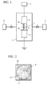
FIG. 1 is a schematic view showing a plasma treatment
apparatus;
FIG. 2 is a plan view showing an example when a separator
material is arranged on an earth electrode;
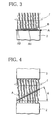
FIG. 3 is a plan view showing another example when a
separator material is arranged on an earth electrode;
FIG. 4 is a side view showing an example when a separator
material is arranged;
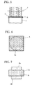
FIG. 5 is a side view showing another example when a
separator material is arranged;
FIG. 6 is a plan view showing an example when a separator
material is arranged on an earth electrode;
FIG. 7 is a plan view showing another example when a
separator material is arranged on an earth electrode;
FIG. 8 is a partial cut-out perspective view showing
a cylindrical nickel-metal hydride secondary battery having the
separator of the present invention incorporated herein;
FIG. 9 is a graph depicting a relationship between a
separator contact angle and a capacity residual ratio (%) in
a nickel-metal hydride secondary battery employed for the
present invention and comparison;
FIG. 10 is a graph depicting the capacity residual ratio
of each battery in Examples 13 to 15 and Comparative Examples
5 to 8;
FIG. 11 is a plan view showing a state in which a
separator material is arranged during manufacture of separator
H according to Example 16;
FIG. 12 is a plan view showing a state in which a
separator material is arranged during manufacture of separator
H according to Example 17;
FIG. 13 is a graph depicting the capacity residual ratio
of each battery according to Examples 16 and 17 and Comparative
Examples 9 and 10;
FIG. 14 is a graph depicting the capacity residual ratio
of each battery according to Examples 18 to 20 and Comparative
Examples 11 to 12;
FIG. 15 is a graph depicting the capacity residual ratio
of each battery according to Example 21 and Comparative Examples
13 to 15; and
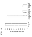
FIG. 16 is a graph depicting the cycle number rate (%)
of each battery according to Example 21 and Comparative Example
13 to 15.
FIG. 17 is a graph depicting the capacity residual ratio
of batteries each including separators Q1 to Q5; and
FIG. 18 is a graph depicting the cycle number rate (%)
of batteries each including separators Q1 to Q5.
DETAILED DESCRIPTION OF THE INVENTION
A battery separator according to the present invention
comprises synthetic resin fibers, and is subjected to
hydrophilization treatment. Hydrophilicity by the
hydrophilization treatment is such that a contact angle
relative to pure water indicates a value of 0 to 100 degrees.
Specifically, synthetic resin fibers being a starting
material of the separator according to the present invention
include polyolefin fibers such as polyethylene fibers or
polypropylene fibers or itself; complex fibers having their
core-sheath structures in which a surface of a polyolefin fiber
is covered with a different kind of polyolefin fiber; and
complex fibers having their separate structures of different
kinds of polyolefin fibers from each other. In addition, PTFE
fibers can be used, but in this case, the entire mechanical
strength may be increased by mixing inorganic fibers such as
glass fibers, for example. The above mentioned fibers are
hydrophobic in their surfaces.
Since the separator according to the present invention
employs a material having its superior oxidization proof, even
if the separator comes into contact with an alkali electrolyte,
it is not hydrolyzed, and impurities causing the aforementioned
shuttle reaction is not produced. For example, reduction of
a charged product(nickel oxy-hydroxide)in a nickel electrode
is not promoted.
Although the separator material is preferably formed
of a non-woven fabric made of the above mentioned fibers, it
may be formed of finely porous plastic sheets. When the
separator material is formed of a non-woven fabric, the
non-woven fabric allows the above mentioned fibers to be woven
by a dry-type method, wet method, a span bond method, a melt
blow method or the like.
When the separator material is formed of a non-woven
fabric, the basis weight is preferably 30 to 70 g/m2. If the
non-woven fabric is smaller than 30 g/m2 in basis weight, the
separator material strength is low, and thus, the material is
easily damaged during winding when the aforementioned electrode
groups are manufactured. Conversely, if the cloth is heavier
than 70 g/m2 in basis weight, the occupying volume of the
separator when the electrode groups are manufactured is
increased, and the electrode capacity is lowered.
In addition, there is preferably employed a separator
material in which the specific surface area during measurement
with a BET 1-point method using nitrogen indicates 0.5 to 5.0
m2/g. When a separator material whose specific surface area
is less than 0.5 m2/g is employed, the electrolyte absorption
properties of the manufactured separator is lowered. In
addition, when a separator material whose specific surface area
is bigger than 5.0 m2/g is employed, its tension strength is
lowered, the separator is easily deformed, and the separator
is easily damaged during winding when the electrode groups are
manufactured. A separator material whose specific surface
area is 1.0 to 4.0 m2/g is particularly preferred.
The separator according to the present invention is
manufactured by applying hydriphilization treatment described
later to the separator material, and hydrophilicity indicated
by the above mentioned contact angle is imparted.
The contact angle denotes a value obtained when a
manufactured separator (about 2.5 cm in length and 10 cm in
width) is placed horizontally; pure water (about 10 µl) is
dropped on a surface of this separator, and left as is for 1
minute, the pure water is absorbed into a network of separator,
and then, a contact angle of water droplets existing on the
separator surface is measured by an optical microscope (for
example, a goniometer type contact angle measuring instrument).
That is, when this value is small, it denotes that a
separator has its preferable hydrophilicity, and the separator
itself has its superior alkali electrolyte absorption
properties. Conversely, when the value is great, it denotes
that the separator exhibits water repellency, and the alkali
electrolyte absorption properties are impaired. In the case
of a non-woven fabric made of polyolefin based synthetic resin
fibers without hydrophilization treatment described later, for
example, its contact angle indicates a value from 120 to 130
degrees.
In the case where a contact angle of the separator
exceeds 100 degrees, an alkali electrolyte insufficiently
permeates into the separator, and an internal resistance of a
battery rises because the separator has its inferior
electrolyte absorption properties. In addition, since an
alkali electrolyte is not maintained sufficiently in a network
of fibers constituting the separator, the electrolyte does not
spread sufficiently in the battery, and the initial capacity
is lowered. Alternately, the alkali electrolyte maintained in
the separator is absorbed by a bonding agent for the positive
and negative electrodes or expansion of the positive electrode.
In the case where the nickel-metal hydride secondary battery
is maintained at a high temperature, a hydrogen gas left from
a negative electrode permeates the separator, reaches a surface
of a positive electrode, and reduces a nickel oxy-hydroxide of
the positive electrode. Thus, self-discharge properties are
lowered.
On the other hand, when the above contact angle is within
the range of 0 to 100 degrees, fibers constituting the separator
is sufficiently hydrophilized, and thus, an alkali electrolyte
permeates and is maintained in a very small space inside of the
separator. This alkali electrolyte is maintained in a network
of fibers constituting the separator, and its movement is
prevented. Thus, the electrolyte in the separator resists
against an action from a positive or negative electrode to
absorb the alkali electrolyte. Further, in the case of the
nickel-metal hydride secondary battery, a water screen is
rigidly formed on a surface of the positive electrode arranged
in intimate contact with the separator by the alkali electrolyte
maintained in the network of fibers constituting the separator.
Thus, the hydrogen gas left from the negative electrode is
suppressed from permeating the separator and directly reaching
the surface of the positive electrode. As a result, self-discharge
is restricted.
As a hydrophilization treatment method, although there
may be any one of the conventionally known methods including
acrylic acid graft treatment, sulphonation treatment,
fluoridation treatment or the like, it is preferred to apply
plasma treatment to which attention is recently focused as a
surface reforming method. This plasma treatment is carried out
in an gas phase, thus making it possible to introduce a
hydrophilic group throughout the network of fibers constituting
the separator material and increase a reduction effect of a
contact angle. In addition, in comparison with sulphonation
treatment, impurities are less produced during
hydrophilization treatment.
Now, plasma treatment preferably employed as
hydrophilization treatment according to the present invention
will be described.
In the plasma treatment apparatus to be employed, as
shown in FIG. 1, an earth electrode 2 and a power electrode 3
are arranged in parallel with a predetermined interval in a
closed container 1, and the power electrode 3 is connected to
a power source 4. Respective opposite faces 2a and 3b of the
earth electrode 2 and the power electrode 3 are generally shaped
in circles of their predetermined diameter. A pressure
reducing mechanism 5 is connected to the closed container 1 so
that an internal pressure of the closed container 1 can be
reduced to a predetermined degree of vacuum.
In addition, a gas supply mechanism 6 is connected to
the closed container 1. When an apparatus is operated, a gas
described later is supplied into the container therefrom,
whereby a hydrophilic functional group can be introduced on a
surface of a separator material targeted for treatment.
When this apparatus is operated, separator material A
targeted for treatment is arranged between the earth electrode
2 and the power electrode 3. In general, the separator material
is arranged on a surface of the earth electrode 2. Then, the
pressure reducing mechanism 5 is operated, and the internal
pressure of the closed container 1 is temporarily reduced.
Further, while a predetermined gas is supplied from the gas
supply mechanism 6, the inside of the closed container 1 is
maintained to 0.05 to 1 Torr in degree of vacuum, for example.
The power electrode 3 and the earth electrode 2 are operated,
a high-frequency electric field is formed between these
electrodes, and a plasma 'f' is generated therebetween.
Specifically, in an output of 5 to 1,000 W, power
discharge is carried out using high-frequency of 13.56 MHz in
radio frequency or microwaves of 2.54 GHz, and plasma treatment
is applied to the separator material A arranged between the
electrodes. The treatment time is preferably set to 0.1 to 30
minutes.
If plasma treatment is carried out under conditions
different from the above treatment conditions,
hydrophilization treatment becomes insufficient though the
treatment conditions may vary depending on the distance between
the power and earth electrodes and the electrode diameters,
making it difficult to ensure movement of ions or water required
for battery reaction. Further, on the contrary, plasma
reaction is excessively promoted, fibers constituting a
separator material are cut or destroyed, the separator material
is deformed due to thermal shrinkage, thus making it difficult
to incorporate the separator into a battery.
An example of parameters for plasmas generated under
the above conditions is shown as follows: 2000 to 4000° K in
electron temperature; 109 to 1013 pieces/cm3 in electron density;
200 to 400° K in ion temperature; 109 to 1013 pieces/cm-3 in ion
density; and 10 to 90 V in plasma spatial potential.
In plasma treatment carried out under the above
conditions, at least gas for imparting hydrophilicity is
supplied from the gas supply mechanism 6.
As the gas for imparting hydrophilicity, there can be
used a gas for introducing a hydrophilic functional group such
as carbonyl group, carboxyl group, hydroxide group, amino group,
or imino group into fibers constituting the separator material,
for example, one or two or more selected from oxygen gas,
nitrogen gas, air, nitrogen oxides, ammonia, and carbon
dioxide.
By the above plasma treatment, a hydrophilic functional
group such as hydroxide group, carbonyl group, carboxyl group,
hydroxide group, amino group, or imino group is chemically
introduced into and fixed to a surface of fibers constituting
the separator material. In particular, the hydroxide group,
carbonyl group, or carboxyl group has its great polarity and
superior hydrophilicity. Unlike the amino or imino group, it
does not contain a nitrogen atom, and does not cause self-discharge
due to shuttle reaction. From the foregoing, as a
functional group, the hydroxide group, carbonyl group, or
carboxyl group is preferably introduced.
Therefore, the above plasma treatment is preferably
applied in an atmosphere containing an oxygen gas. In this case,
only the hydroxide group, carbonyl group, or carboxyl group is
introduced into and fixed to fibers constituting the separator
material by the oxygen contained in the above atmosphere, and
further, there is lower possibility of causing shuttle reaction
due to the presence of the amino group. In particular, it is
preferable that the above atmosphere is substantially composed
of only the oxygen gas. If the rate of oxygen gas contained
in the atmosphere is low, the above hydroxide group is hardly
formed, an amino group or the like is formed due to the nitrogen
gas mixed in the atmosphere, and the amino group or the like
can be introduced. In addition, in the case where radicals are
formed in fibers constituting the separator material by plasma
treatment, when the air is introduced into the apparatus by
releasing the pressure reduction in the apparatus, the nitrogen
or the like in air may react with the radicals in fibers.
From the gas supply mechanism 6, a gas for imparting
hydrophobicity may be mixed with the above gas for imparting
hydrophilicity to be supplied.
As the gas for imparting hydrophobicity, there can be
used a gas capable of introducing a hydrophobic group into
fibers constituting the separator, for example, tetra-fluorinated
carbon, tetra-fluorinated ethylene, or hexa-fluorinated
ethane.
With respect to the mixture rate of the gas for imparting
hydrophilicity to the gas for imparting hydrophobicity, the
partial pressure of the former is preferably 30% or more.
If the mixture rate is outside the above value or if
the plasma treatment conditions are outside the aforementioned
range, a balance between hydrophilicity and hydrophobicity in
the separator after the treatment is worsened, possibly causing
inconvenience that ion or water movement during battery
reaction is not smoothly promoted; causing breakage of fibers
constituting the separator or separator deformation due to
thermal shrinkage; or causing inconvenience that manufacturing
of electrode groups is difficult.
Although the above example assumes that plasma
treatment is carried out in a mixture gas between the gas for
imparting hydrophilicity and the gas for imparting
hydrophobicity, separator material treatment is not limited to
the above mode. The plasma treatment may be carried out in the
gas for imparting hydrophobicity after being carried out in the
gas for imparting hydrophilicity and vice versa.
In an alkali secondary battery in which the above plasma
treatment is applied to a separator material, and then, an
electrode group manufactured using the separator is
incorporated, in particular, in the nickel-metal hydride
secondary battery, self-discharge is effectively restricted.
The reason is not clear, but is considered as follows:
A hydrophilic functional group and a hydrophobic group
are introduced into fibers constituting the separator by the
above mentioned plasma treatment, whereby a hydrophilic part
and a hydrophobic part coexist in the separator at a
predetermined area rate. It is considered that the hydrophobic
part traps nitrogen radicals associated with its self-discharge
or the impurities eluted from an active substance to induce
self-discharge. In addition, the hydrophilic and hydrophobic
parts coexist, whereby distributions of the alkali electrolytes
in the separator change. It is also considered that the
hydrogen gas discharged from a negative electrode hardly
reaches a positive electrode as a result of such change.
In addition, plasma treatment using inert gas such as
Ar or He is carried out for the separator, radicals are generated
at the constituent fibers, and then the plasma treated separator
may be removed in air. In this case, with the generated radicals
as a medium, a hydrophilic functional group such as hydroxide
group is introduced into the constituent fibers.
During the above plasma treatment, the entire surface
of the separator material is included in the generated plasmas.
Thus, in the case where the entire surface of the separator
material is not plasma-treated rather than in the case where
the entire surface is plasma-treated uniformly, the self-discharge
properties of the alkali secondary battery assembled
by using the obtained separator, in particular, those of the
nickel-metal hydride secondary battery are improved more
significantly.
That is, a separator in which an area whose surface has
a certain difference in hydrophilicity is formed achieves an
improved effect in self-discharge properties.
The above state in which an area whose surface has a
certain difference in hydrophilicity denotes as follows: The
surface of the plasma-treated separator is not made uniformly
by carrying out plasma treatment as described later. In one
separator, the entire surface is hydrophilized, but a part of
the surface is strongly plasma-treated in plane or in thickness
direction, and a hydrophilic functional group is introduced in
large quantity and rigidly. A functional group is less
introduced or is not introduced into the remaining part at all,
and hydrophobicity of synthetic fibers being a separator
material still remains.
Such area having a certain difference in hydrophilicity
can be formed as follows.
For example, as shown in FIG. 2, when separator material
A is placed on an earth electrode 2 and treated with the surface
of the earth electrode such that it is completely covered, a
portion A1 of the separator material A is plasma-treated
strongly than a portion A2 positioned in the outside of the earth
electrode, resulting in a high hydrophilic area. Moreover, at
the above portion A1, the central part is plasma-treated more
strongly. Thus, the hydrophilicity of the portion A1 is the
highest at the center part, and is reduced more gradually at
the outer side.
Therefore, the entire surface of the separator after
the treatment becomes hydrophilic, and moreover, an area having
its different hydrophilicity is formed from its center part to
the outside.
In addition, in the case of an arrangement mode as shown
in FIG. 3, an area having a certain difference in hydrophilicity
can be formed as follows:
First, separator material A targeted for treatment is
placed on the earth electrode 2. Then, on this separator
material A, material B, which is smaller than the material A
and in which plasmas can be transmitted, for example, a material
identical to the separator material A is further placed, and
is treated by plasma 'f'.
Portion A3 positioned in the outside of separator B is
strongly treated by the plasma 'f', resulting in being a high
hydrophilic area. However, although portion A4 covered with
material B is treated by plasmas which has transmitted the
material B, the degree of treatment is smaller than in the case
of portion A3, and the hydrophilicity of the portion A4 is lower
than that of the portion A3.
In this case also, an area having a certain difference
in hydrophilicity is formed on the surface of the separator
obtained after the treatment.
Further, in place of directly placing the separator
material A targeted for treatment on the earth electrode 2 as
described previously, the material A may be arranged with the
material being inclined between the earth electrode 2 and the
power electrode 3 at a predetermined angle as shown in FIG.
4.
In this case, the entirety of the separator material
A included in the plasma 'f' is not treated uniformly by the
plasma 'f', and the treatment state varies along an inclined
face. Therefore, a hydrophilic area in which hydrophilicity
varies slantwise is formed on the surface of the separator
obtained after the treatment.
As shown in FIG. 5, after the separator material A
targeted for treatment has been placed on the earth electrode
2, mask C of a predetermined pattern consisting of titanium and
stainless steel, for example, which do not transmit plasma, for
example, may be further placed and treated thereon.
In this case, since a portion of the separator material
positioned immediately beneath mask C is not plasma-treated,
the hydrophobicity of the constituent resin fibers remains as
it is, and the other portion is plasma-treated, and is converted
to a hydrophilic area.
Therefore, in this case, the hydrophilic and
hydrophobic area coexist on the surface of the separator
obtained after the treatment.
In addition, during separator material plasma
treatment, the separator material A is preferably arranged so
that the surface of the earth electrode 2 is not exposed.
Specifically, as shown in FIG. 6, separator material
A larger than the earth electrode in size is employed, and is
arranged so as to cover the full surface of the surface 2a of
the earth electrode 2. When the surface 2a of the earth
electrode 2 is larger than the separator material A in size,
as shown in FIG. 7, a portion 2b exposed toward the power
electrode 3 without being covered with the separator material
A may be covered with another insulation material 2B such as
polypropylene film, for example.
In this manner, when plasma treatment is carried out
with the surface 2a of the earth electrode 2 being not exposed,
it is considered that a hydrophilic functional group is
preferably introduced into the surface of the separator
material A for the reasons stated below.
In general, when plasmas are generated with gas being
introduced, the generated field is composed of electrons, gas
ions, radicals, lights or the like. C-H bond of a synthetic
resin constituting separator material A is attacked by these
electrons, ions, radicals or the like, H is left. Thereafter,
radicals are formed, and a functional group of the generated
gas is introduced herein, thereby separator material
hydrophilization is promoted. The above process is advanced
as competitive reaction, and the functional group into which
a constituent resin of the separator material is temporarily
introduced may be left again depending on operating conditions.
At this time, when plasma treatment is carried out with
the earth electrode 2 being larger than the separator material
A arranged thereon in size, a sheath voltage of the power
electrode is higher than that of a site covered with the
separator material A in the vicinity of the exposed earth
electrode. Thus, electrons, ions or the like flying in the
vicinity thereof are accelerated, and their motion energies are
increased.
A portion of the separator material A positioned in the
vicinity thereof are severely attacked by particles having
large motion energies, in particular, ions of the generated gas.
So, it is considered that the temporarily introduced functional
group, for example, is purged again or that a chain-like lattice
part of resin fibers constituting the separator material A is
attacked, and is cut or destroyed. That is, it is considered
that separator material hydrophilization is inhibited, and the
separator material itself is damaged.
On the contrary, in the case where the surface of the
earth electrode 2 is not exposed, the above mentioned
circumstance hardly occurs. In addition, the separator
material A is electrically charged due to the flied ions or
electrons, and radicalization action of the separator material
against the resin fibers due to ions is effectively promoted.
As a result, it is considered that the functional group is
effectively introduced into the fibers.
Therefore, the obtained separator is structured so that
a functional group is introduced into resin fibers constituting
the separator, and moreover, is structured to be hardly damaged.
In the above mentioned plasma treatment, in the case
where excessive hydrophilization treatment is applied in the
thickness direction of the separator, when the separator is
incorporated in a battery, the separator excessively stores an
alkali electrolyte, resulting in deterioration of battery
properties. In addition, the strength of fibers constituting
the separator may be lowered and damaged during manufacture of
electrode groups.
In view of the foregoing, for example, in the case where
plasma treatment is carried out using O2, when ESCA measurement
is performed for the separator after the treatment,
hydrophilization is preferably obtained such that the O/C ratio
in a site of at least 20 Å in depth indicates a value of 0.01
to 0.6.
Now, an alkali secondary battery having the separator
incorporated herein, in particular, a nickel-metal hydride
secondary battery will be described.
Separator made by the method described-above is
intervened between a positive and negative electrodes, to make
electrode groups. The electrode groups are sealed in the
battery case with alkali battery electrolyte. Thus, alkali
secondary battery of the invention is assembled.
The structure of alkali secondary battery of the
invention is described with nickel-metal hydride secondary
battery as an example.
In FIG. 8, in a bottomed cylindrical battery case 11,
there is housed an electrode group 15 in which a sheet having
a positive electrode (nickel electrode) 12, a separator 13
according to the present invention as described previously, and
a hydrogen absorbing alloy electrode (negative electrode) 14
laminated thereon is wound in spiral shape. The negative
electrode 14 is arranged on the outer-most side of the electrode
group 15, thereby coming into electrical contact with the
battery case 11. In addition, the bottom of the electrode group
15 is positioned on the insulation plate 16 arranged on the
bottom of the battery case 11.
A ring-shaped insulation gasket 17 is arranged inside
of a top opening of the battery case 11, and a first disc-shaped
sealing plate 19 having a hole 18 at the center thereof is
arranged in a state in which the periphery of this insulation
gasket 17 bites with the ring-shaped insulation gasket 17.
Clamping process is carried out such that the top opening of
the battery case 11 is reduced inwardly in diameter, whereby
the first sealing plate 19 seals the top opening of the battery
case 11 via the insulation gasket 17 in air tightness.
In addition, a lead terminal 20 is additionally
provided at the upper part of the electrode group 15, and this
lead terminal 20 is welded with a lower face of the first sealing
plate 19. A rubber based safety valve 21 is arranged so as to
occlude a center hole 18 of the first sealing plate 19. Further,
a hat-shaped positive electrode terminal 22 is welded with the
first sealing plate 19 so as to cover the valve, and the electrode
group is sealed.
In addition, at the upper part of the battery case thus
structured, a press plate 23 of an insulation material having
a center hole is arranged with only the positive electrode
terminal 22 being extruded from the center hole. Further, an
enclosure tube 24 is arranged to cover the periphery of the press
plate 23 and the side face and bottom face of the battery case
11.
The battery according to the present invention is not
limited to the above mentioned cylinder shape. For example,
a rectangular battery may be structured such that the nickel
electrode (positive electrode), separator, and hydrogen
absorbing alloy electrode (negative electrode) are laminated
each other to form a rectangular electrode group, and the
electrode group is housed and sealed in a rectangular battery
case.
The nickel electrode 12 of the electrode group 15 is
generally manufactured as follows:
First, active substance powders consisting essentially
of nickel oxides are mixed with a bonding agent such as a
carboxymethyl cellulose, methyl cellulose, a sodium
polyacrylic acid, polytetrafluoroethylene, or a
hydropropylmethyl cellulose, the entirety is mixed by water to
prepare a viscous paste. Elements such as Co, Cu, Zn, Al, Mn,
Ca, Mg, Fe, or Si are solidly dissolved in nickel oxides
employed.
Next, this paste is filled in and applied to a collector
having its three-dimensional net-shaped structure such as a
sponge-like nickel substrate, a net-shaped sintered metal fiber
substrate, or a felt plating substrate in which nickel plating
is applied to non-woven fabric. Thereafter, the paste is dried,
and further, is pressurized and molded to make a positive
electrode sheet of its predetermined thickness. At this time,
as a collector, there can be employed a two-dimensional
substrate such as a punched metal or expanded metal, 2.5-dimensional
substrate whose structure has burring at an opening
of the punched metal or the like.
When an active substance is employed in which a
higher-order oxide of the above mentioned cobalt is formed on
a surface of part or whole of the powders consisting essentially
of nickel oxides, the assembled nickel-metal hydride secondary
battery has improved self-discharge properties and improved
charge and discharge cycle life performance by multiple action
of the above separator.
Now, a preferred manufacturing method of such active
substance will be described.
First, as a starting material during manufacture of an
active substance, there is provided granules in which particles
consisting essentially of nickel hydroxides are charged in an
alkali aquous solution controlled to pH11 to pH13, a cobalt
sulfate aquous solution is gradually added thereto, whereby
cobalt compounds such as cobalt hydroxides are deposited on a
surface of the particles to cover the surface of the particles;
or granules wherein particles made of cobalt metals, cobalt
hydroxides, cobalt trioxides, tri-cobalt tetra-oxides, cobalt
monoxides or a mixture of two or more kinds thereof are added
to particles consisting essentially of nickel hydroxides.
In this case, the contents of the cobalt metals or cobalt
compounds in the above granules are preferably set to within
the range of 0.5 to 20 % by weight. If the contents are less
than 0.5 % by weight, the aforementioned conductive matrix is
insufficiently formed in a nickel electrode supporting the
obtained active substance, and the utility of the active
substance is not increased. If the contents are greater than
20 % by weight, a relative rate of nickel hydroxide particles
in the active substance decreases, and the battery discharge
capacity is lowered.
First, the above mentioned granules are mechanically
stirred in an alkali aquous solution, and the alkali aquous
solution and granules are mixed uniformly.
As an alkali aquous solution at this time, there can
be employed a sodium hydroxide aquous solution, a potassium
hydroxide aquous solution, or a solution prepared by mixing a
lithium hydroxide aquous solution with a mixture of these
solutions.
At this time, the concentration of an alkali aquous
solution is preferably set to within the range of 1 to 14N. If
the concentration is lower than 1N, the solubility of the cobalt
metals or cobalt compounds contained in granules becomes low,
the aforementioned conductive matrix is formed insufficiently,
and the utility of active substances is not increased so much.
In addition, if the concentration is higher than 14N, the
viscosity of the alkali aquous solution is increased, the alkali
aquous solution does not permeate to the inside of the granules,
whereby the cobalt metals or cobalt compounds cannot be
dissolved sufficiently.
At this time, although the alkali aquous solution and
granules may be mixed with each other and stirred under room
temperature, the mixing and stirring may be carried out under
heating conditions of about 35 to 110 °C.
During a process for mixing and stirring the alkali
aquous solution and granules, the alkali aquous solution is
deposited uniformly on the surface of the granules, and
permeates to the inside thereof. As a result, a part of the
cobalt metals or cobalt compounds contained in the granules is
dissolved in the alkali aquous solution.
For example, while the alkali aquous solution and
granules are thus mixed with each other and stirred in an
oxygen-containing atmosphere such as air, they are further
mixed uniformly, and are irradiated with irradiation rays,
preferably microwaves from magnetron for 20 minutes.
The microwave, when radiated to the mixture of the
alkali aqueous solution and the granules, serves to vibrate
water molecules contained in the mixture and surrounding the
individual particles, thereby uniformly heating the mixture,
that is, the granules. The cobalt component dissolved in the
alkali aquous solution is oxidized under the existence of oxygen,
changes to conductive cobalt oxy-hydroxides, and is deposited
on the surface of nickel oxide particles that are main
components of the granules.
At this time, the heat treatment temperature of the
mixture of the granules and alkali aqous solution is preferably
set to 35 to 160°C. If the temperature is lower than 35°C,
the cobalt metals or cobalt compounds contained in the granules
are less dissolved in the alkali aquous solution, the conductive
matrix is formed insufficiently, and the utility of active
substances is not increased so much. In addition, if the
temperature is higher than 160°C, a structural change of the
nickel hydroxide particles itself takes place, and active
substances deteriorates.
With respect to manufacture of active substances,
although the above mentioned method is preferred, for example,
there may be employed a method for synthesizing higher-order
oxides of cobalt in advance and depositing the oxides on the
surface of nickel hydroxide powders by a spattering method or
the like.
Next, the negative electrode 14 is manufactured as
follows: A paste having the hydrogen absorbing alloy powders,
bonding agent, and, if required, a conductive material such as
carbon black, for example, mixed with each other by water is
filled in and applied to a collector, and then, is dried, and
molded.
Any of the hydrogen absorbing alloys capable of
electrochemically absorbing and discharging hydrogen may be
employed without being particularly limited. For example,
there can be exemplified a multiple element system in which
LaNi5, MmNi6 (Mm denotes a misch metal), LmNi5 (Lm denotes a
lanthanum enriched misch metal), or one part of Ni is
substituted by Al, Mn, Co, Ti, Cu, Zn, Zr, Cr, B or the like;
TiNi system, TiFe system, MgNi system or a mixture system
thereof. In particular, the hydrogen absorbing alloys
represented by the formula; LmNixAlyAz ('A' denotes at least one
kind selected from Al and Co, and x, y, and z denote an atom
ratio meeting 4.8 ≦ x + y + z ≦ 5.4) is preferred in that fine
particulate during a charge and discharge cycle is restricted,
and the battery charge and discharge cycle life performance can
be improved.
In addition, the bonding agent includes the polymeric
materials employed during manufacture of a nickel electrode 12.
The collector includes, for example, a two-dimensional
substrate such as a punched metal, an expanded metal, a punched
steel plate, or a nickel net or a three-dimensional net-shaped
structure such as a felt-shaped metal porous body or a
sponge-like metal substrate.
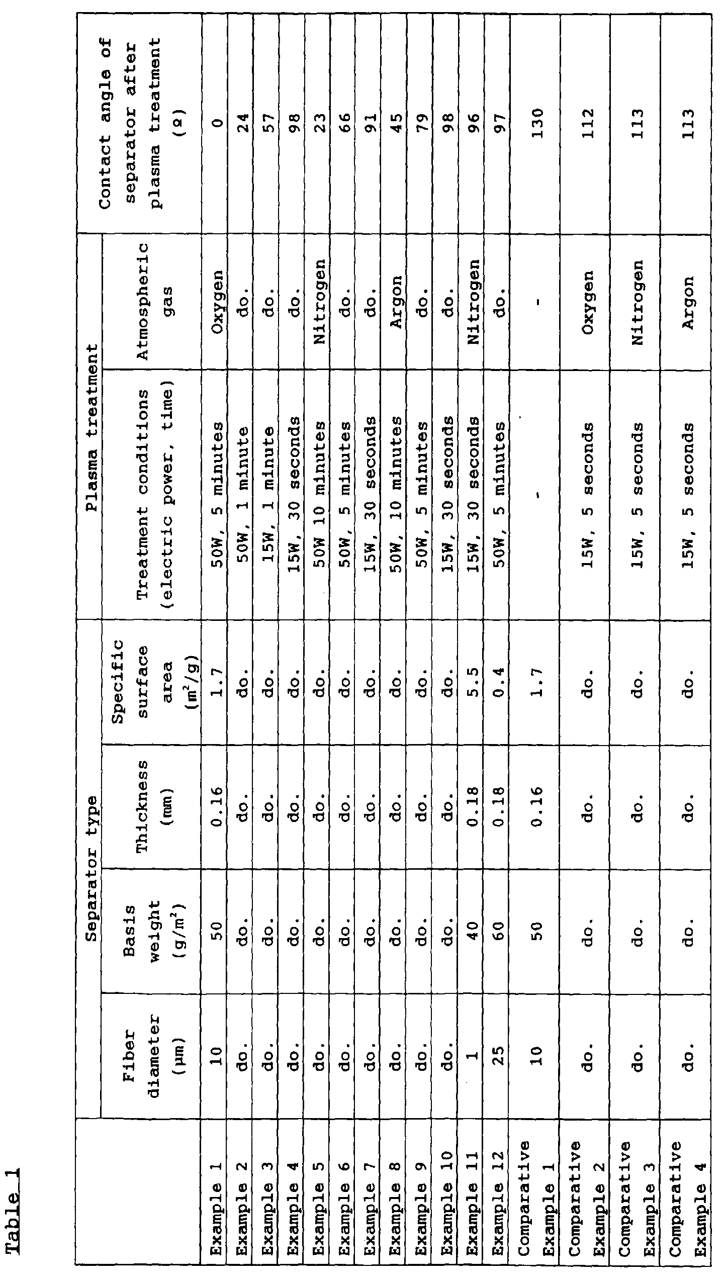
Examples 1 to 12 and Comparative Examples 1 to 4
1. Manufacture of Separator
From long fibers of 10 µm in average diameter or
continuous fibers constituting a polypropylene resin, non-woven
fabric of 50 g/m2 in basis weight, 0.16 mm in thickness,
10 cm in width, and 10 cm in length was fabricated by a span
bond method. This non-woven fabric was dried at 80°C for 30
minutes, and water adhered to the non-woven fabric was removed.
Under room temperature, a specific surface area was measured
by a nitrogen BET 1 point method. The specific surface area
was 1.7 m2/g.
The non-woven fabric was arranged on an earth electrode
of the plasma treatment apparatus (the earth electrode and the
power electrode are 90 mm in diameter, and a distance between
these electrodes is 40 mm) shown in FIG. 1, and the internal
pressure of a closed container was reduced to about 10-6 Torr.
Then, an oxygen gas of 99.9 % in impurity was supplied at a flow
rate of 30 ml/min, and the internal pressure of the container
was adjusted to 13.3 Pa. In other samples, a nitrogen gas of
99.9 % in purity or an argon gas of 99.9% in purity was introduced
under the similar conditions to the above instead of the oxygen
gas.
Next, plasma treatment was carried out at a frequency
of 13.56 Hz and at a power (W) and processing time shown in Table
1, the internal pressure is reset to an atmospheric pressure,
the non-woven fabric was removed, and cut out in the shape of
a strap of 100 mm in length and 40 mm in width to make a separator.
In Example 11, a separator of predetermined type shown
in Table 1 was manufactured from polypropylene resin fibers
using a melt blow method. In Example 12, the separator of
predetermined type shown in Table 1 was manufactured from
complex fibers of polypropylene and polyethylene resins using
a dry-type method.
2. Manufacture of the Positive Electrode
Powders consisting of nickel hydroxide powders of 90
parts by weight and cobalt oxide powders of 5.5 parts by weight
were mixed with each other. A sodium polyacrylic acid of 0.14
parts by weight, a hydroxypropyl methyl cellulose of 0.05 parts
by weight, a carboxy methyl cellulose of 0.1 parts by weight,
PTFE dispersion (specific gravity 1.5 and solid component of
60 % by weight) of 0.6 parts by weight (conversion of the solid
component), and pure water of 2.7 parts by weight were added
to nickel hydroxide powders of 90 parts by weight and mixed with
the above mixture to make a paste.
This paste was first filled in and applied to cavities
of a nickel plated substrate foam, and further, the paste was
applied and dried on the substrate surface. Next, this
substrate was roller-pressed and rolled to make a positive
electrode (a nickel electrode).
3. Manufacture of the Negative Electrode
Commercially available Lm, Ni, Co, Mn, and Al were mixed
with each other, and heated and fused by a high-frequency
furnace, and a hydrogen absorbing alloy ingot of LmNi 4.0 Co 0.4
Mn 0.3 Al 0.3 in composition was fabricated. This ingot was
mechanically milled, and powders under 200 meshes (Tyler
screen) were obtained.
To these powders of 100 parts by weight, there were added
and mixed a sodium polyacrylic acid of 0.3 parts by weight, a
carboxy methyl cellulose of 0.05 parts by weight, PTFE
dispersion (specific gravity of 1.5 and solid component of 60%
by weight) of 1.0 parts by weight (conversion of the solid
component), carbon powders (conductive material) of 1.0 parts
by weight, and pure water of 44 parts by weight to make a paste.
This paste was applied to a nickel plated steel plate
based punched metal, and the paste was dried. Then, the
substrate was roller-pressed and rolled to make a negative
electrode (a hydrogen absorbing alloy electrode).
4. Battery Assembly
A plasma treated separator was intervened between the
above negative and positive electrodes, and was spirally wound
with the negative electrode being outside thereof to make an
electrode group, and the electrode group was housed in a battery
case. Then, an alkali electrolyte consisting of a KOH aquous
solution of 7N and a LiOH aquous solution of 1N was injected
in a battery case, and was sealed, and then, a cylindrical
nickel-metal hydride secondary battery of AAA size was
assembled.
5. Measurement of Contact Angle
Each separator of 2.5 cm in length and 5 cm in width
was horizontally placed, a pure water of 10 µL was dropped at
5 sites with intervals of 1cm, and an average value of a contact
angle after an elapse of 1 minutes was obtained. Measurement
was carried out by a goniometer type contact angle measuring
instruments. The contact angle in each embodiment is shown in
Table 1.
The smaller value of the contact angle denotes superior
hydrophilicity.
6. Evaluation of Self-discharge Properties
The above battery was charged at 0.2C and 150% with
respect to a nominal capacity at 20 °C, and then charging and
discharging were repeated by 3 cycles, 1 cycle of which was
defined as discharging carried out until the battery voltage
had reached 1.0 V at 1C. At this time, a discharge capacity
(residual capacity) obtained from the current value during
discharge and the time required for discharge was defined as
C0.
Then, the battery was stored in a 45°C thermostat vessel
for 14 days in a state in which 150% discharging was carried
out at 0.2C.
Then, discharging were carried out until the battery
voltage had reached 1.0 V at 1C. At this time, the discharge
capacity (residual capacity) was defined as CR.
The capacity residual ratio (%) was calculated as
(CR/C0) x 100.
In FIG. 9, there is shown the capacity residual ratio
(%) with respect to the contact angle of the separator in the
case where the atmospheric gas for plasma treatment were changed
to oxygen, nitrogen, and argon with respect to each Example.
In the figure, an open circle denotes a relationship between
the separator and the contact angle when plasma treatment is
not performed.
In FIG. 9, the upper position denotes the superior
self-discharge properties.
The following is evident from Table 1 and FIG. 9.
In the above Examples, although a case in which plasma
treatment is applied has been described, if the contact angle
of the separator is within the above range, it is observed that
the similar effect is achieved when acrylic acid graft
treatment, sulphonation treatment, or fluoridation treatment
is applied.
Further, in the above Examples, although a cylindrical
nickel-metal hydride secondary battery has been described, the
present invention is applicable to a rectangular nickel-metal
hydride secondary battery, similarly.
Examples 13 to 15 and Comparative Examples 5 to 8
(1) Manufacture of Separator
A non-woven fabric of 50 g/m2 in basis weight and 0.16
mm in thickness was fabricated with a Span Bond method using
polypropylene fibers of 10µm in average of fiber diameter.
This separator was defined as separator material (1).
A non-woven fabric of 40 g/m2 in basis weight and 0.18
mm in thickness was fabricated with a Melt Blow method using
polypropylene fibers of 1 µm in average of fiber diameter.
This separator was defined as separator material (2).
Further, a dry-type non-woven fabric of 60 g/m2 in basis
weight and 0.18 mm in thickness was fabricated using complex
fibers consisting of polypropylene fibers and polyethylene
fibers each of 25 µm in average fiber diameter. This is defined
as separator (3).
These non-woven fabrics are arranged between
electrodes of the plasma treatment apparatus, and 1-hour
pressure-reducing operation was carried out. Thereafter, a
gas indicated in the apparatus was flown herein at a flow rate
of 30 ml/min, plasma treatment was carried out under the
conditions shown in Table 2 with the inside of the apparatus
being adjusted to 0.1 Torr, and various separators were
manufactured.
Each separator after the treatment was heated at a
temperature of 80°C for 30 minutes, and then, a specific
surface area therefor was measured with BET 1 point method using
nitrogen. The results are shown in Table 2. In addition, the
contact angle of each separator was measured, and the
measurement values are shown in Table 2.
Cobalt oxide powders of 6.1 parts by weight, a sodium
polyacrylic acid of 0.16 parts by weight, a hydroxy methyl
cellullose of 0.06 parts by weight, a carboxy methyl cellulose
of 0.11 parts by weight, and PTFE dispersion (specific gravity
of 1.5 and solid content of 60 % by weight) of 0.67 parts by
weight were mixed with each other to nickel hydroxide powders
of 100 parts by weight. Further, pure water of 30 parts by
weight are added, the entirety was mixed, and a paste was
prepared.
This paste was filled in nickel foam substrate, was
dried, and was rolled, and a nickel electrode (a positive
electrode) of 0.6 mm in thickness was manufactured.
On the other hand, a hydrogen absorbing alloy of
LmNi4.0Co0.04Mn0.3Al0.3 in composition ('Lm' denotes a La enriched
misch metal) was mechanically milled, and powders under 200
meshes (Tyler screen) were obtained.
Then, a sodium polyacrylic acid of 0.3 parts by weight,
a carboxy methyl cellulose of 0.05 parts by weight, a carbon
black of 1.0 parts by weight, and PTFE dispersion (specific
gravity: 1.5 and solid content: 60 % by weight) of 1.0 parts
by weight were blended to the powders of 100 parts by weight,
the entirety was mixed by water of 44 parts by weight, and a
paste was prepared.
This paste was applied to a nickel punched metal
(opening rate of 45%), was dried, and further, was rolled, and
a hydrogen absorbing alloy electrode (a negative electrode)
in 0.3 mm in thickness was fabricated.
Between these nickel electrode and hydrogen absorbing
alloy electrode, as shown in Table 3, each separator of Table
2 was sandwiched to make a laminate sheet, the hydrogen
absorbing alloy electrode was externally wound, and various
electrode groups 15 shown in FIG. 8 was fabricated.
Separator F was damaged during winding, and an
electrode could not fabricated.
Then, this
electrode group 15 is employed, a mixture
solution made of KOH of 7N and LiOH 1N of 1N was employed as
an electrolyte, and a nickel-metal hydride secondary battery
of AAA size shown in FIG. 8 was manufactured.
| | Type of separator incorporated |
| Example 13 | Separator A |
| Example 14 | separator B |
| Example 15 | Separator C |
| Comparative Example 5 | Separator D |
| Comparative Example 6 | Separator E |
| Comparative Example 7 | Separator F |
| Comparative Example 8 | Separator G |
Each of the obtained batteries was charged at 0.2C and
150% with respect to nominal capacity at a temperature of 20°C,
and then, three charge and discharge cycles were repeated until
the battery voltage reached 1.0 V at 1C. Thereafter, 150%
discharging was carried out at 0.2C, the battery was stored
in a thermostat vessel of 45°C in temperature. After the
storage, discharging was carried out until the battery voltage
was 1.0 V at 1C, and the residual capacity was measured.
When the battery nominal capacity was assumed to be
C0, and the above residual capacity was assumed to be C1, the
capacity residual ratio of each battery was calculated based
on the following formula: 100 x C1/C0 (%). The results are
shown in FIG. 10.
From FIG. 10, the following facts are evident.
1) In all of the cases of Examples 13 to 15 and Comparative
Example 8 wherein hydrophilization treatment and
hydrophobilization treatment were carried out and in the case
wherein only hydrophilization treatment was carried out
(Comparative Example 6), the capacity residual ratios were
increased more significantly than that in the case where plasma
treatment was not carried out (Comparative Example 5), and an
improvement in self-discharge properties was observed.
2) However, in the case of Comparative Example 6, the capacity
residual ratio is lower than that in Examples 13 to 15. From
the foregoing, it is evident that plasma treatment for carrying
out both of hydrophilization and hydrophobilization is more
advantageous than plasma treatment for hydrophilization only.
3) In addition, in the case of separator F whose specific
surface area is as large as 5.5 m2/g, an electrode group cannot
be manufactured due to damage, and the capacity residual ratio
of a battery using separator G whose specific surface area is
0.5 m2/g is low. From the foregoing, it is found that a
separator whose specific surface area is 0.5 to 5.0 m2/g is
preferably employed.
Examples 16 and 17 and Comparative Examples 9 and 10
(1) Manufacture of Separator
The following separator was manufactured using the
apparatus shown in FIG. 1.
First, a non-woven fabric of 50 g/m2 in basis weight
and 0.16 mm in thickness was manufactured with a Span Bond
method using polypropylene fibers of 10 µm in average fiber
diameter.
This non-woven fabric was cut in the shape of a square
of 120 mm in length (L1) and 120 mm in length (L2).
This non-woven fabric was arranged on an earth
electrode 2 of 110 mm in diameter, as shown in FIG. 11. That
is, in this case, the entire surface 2a of the earth electrode
2 was covered with the non-woven fabric.
A pressure reducing process was carried out for a
closed container 1 for 1 hour, an oxygen gas was supplied
therein from a gas supply mechanism 6 at a flow rate of 30 ml/min
and the inside of the container was adjusted to 0.1 Torr. Then,
5-minute plasma treatment was carried out at a radio frequency
of 13.56 kMz and at 50 W in output of an power electrode 3.
After a treated material has been removed from the
apparatus, both ends thereof are cut, and a separator in the
shape of a strap of 100 mm in length (a) and 40 mm in width
(b) was formed as shown in FIG. 11. This is defined as separator
H. The contact angle was 0 degrees.
Plasma treatment was carried out under the conditions
similar to those in the case of separator H, except that the
aforementioned non-woven fabric was cut in the shape of a strap
of 40 mm in width (L1) and 100 mm in length (L2), the cut cloth
was placed on the earth electrode 2 of 110 mm in diameter, as
shown in FIG. 12, and an exposed surface of the earth electrode
was completely covered with a polypropylene film. The thus
obtained separator was defined as separator I. The contact
angle was 0 degrees.
Unlike in the case of separator I, plasma treatment
was carried out for the exposed surface of the earth electrode
without the polypropylene film, and a separator was
manufactured. This separator was defined as separator J. The
contact angle was 0 degrees.
The strap-shaped non-woven fabric was provided as a
separator. The separator was defined as separator K. The
contact angle was 130 degrees.
(2) Manufacture of Battery
A nickel electrode (a positive electrode) and a
hydrogen absorbing alloy electrode (a negative electrode) was
manufactured using the conditions similar to those in Examples
13 to 15.
Between these nickel electrode and hydrogen absorbing
alloy electrode, as shown in Table 4, each of the above
mentioned separators is sandwiched to make a laminate sheet.
Thereafter, the hydrogen absorbing alloy electrode was
externally wound, and
various electrode groups 15 shown in FIG.
8 were manufactured.
| | Type of separator incorporated |
| Example 16 | Separator H |
| Example 17 | Separator I |
| Comparative Example 9 | Separator J |
| Comparative Example 10 | Separator K |
These electrode groups 15 were employed, a mixture
solution made of KOH of 7N and LiOH of 1N was employed as an
electrolyte, and a nickel-metal hydride secondary battery of
AAA size having a structure shown in FIG. 8 was manufactured.
(3) Battery Properties
The capacity residual ratio was measured under the same
conditions as those in Examples 13 to 15. The results are shown
in FIG. 13.
From FIG. 13, the following points are evident.
Examples 18 to 20 and Comparative Examples 11 and 12
(1) Manufacture of Separator
The following separator was manufactured using the
apparatus shown in FIG. 1.
First, a non-woven fabric of 5 g/m2 in basis weight
and 0.16 mm in thickness was manufactured with a Span Bond
method using polypropylene fibers of 10 µm in average fiber
diameter.
This non-woven fabric was cut in a square of 120 mm
in length and 120 mm in length.
The non-woven fabric was arranged on the earth
electrode 2 of 110 mm in diameter as shown in FIG. 11. That
is, in the case, the entire surface of the earth electrode 2
was covered with the above non-woven fabric.
1-hour pressure-reducing treatment was carried out
in a closed container 1, an oxygen gas was supplied therein
from a gas supply mechanism 6 at a flow rate of 30 ml/min, and
the inside of the container was adjusted to 0.1 Torr. Then,
5-minute plasma treatment was carried out at a radio frequency
of 13.56 kHz and at an output of 50 W in power electrode 3.
The thus treated material was removed from the
apparatus, both ends thereof were cut, and a separator in the
shape of a strap of 40 mm in width and 100 mm in length was
formed. This separator was defined as separator L. The
contact angle was 0 degrees.
Next, plasma treatment was carried out in a manner
similar to that in the case of separator L except that the
aforementioned non-woven fabric was cut in the shape of a strap
of 40 mm in width and 100 mm in length, and the cut cloth was
arranged between the earth electrode 2 and the power electrode
3 with the cloth being inclined by an angle () of 20 degrees
relative to the surface of the earth electrode 2 of 110 mm in
diameter, as shown in FIG. 4. The thus obtained separator was
defined as separator M. The contact angle was 0 degrees.
In addition, the strap-shaped non-woven fabric
employed for manufacture of separator M is placed on the earth
electrode 2 of 110 mm in diameter. Further, on the center
portion thereof, as shown in FIG. 3, plasma treatment was
carried out in a manner similar to that in the case of separator
L except that the same type of non-woven fabrics of 40 mm in
diameter were laminated and arranged. The thus obtained
separator was defined as separator N.
Plasma treatment was carried out in a manner similar
to that in the case of separator L except that the strap-shaped
non-woven fabric employed for manufacture of separator M was
placed on the earth electrode of 110 mm in diameter. In this
case, since the size of non-woven fabric to be treated is
smaller than the surface size of the earth electrode, the full
surface of the non-woven fabric is uniformly plasma-treated.
The separator thus obtained was defined as separator O. The
contact angle was 0 degrees. Also, separator P was prepared
using the aforementioned strap-shaped non-woven fabric. The
contact angle was 130°.
(2) Manufacture of Battery
A nickel electrode (a positive electrode) and a
hydrogen absorption electrode (a negative electrode) were
manufactured using the conditions similar to those in Examples
13 to 15.
Between these nickel electrode and hydrogen absorbing
alloy electrode, as shown in Table 5, each of the above
mentioned separators is sandwiched to make a laminate sheet,
and the hydrogen absorbing alloy electrode was externally wound,
and
various electrode groups 15 shown in FIG. 8 were
manufactured.
| | Type of separator incorporated |
| Example 18 | Separator L |
| Example 19 | Separator M |
| Example 20 | Separator N |
| Comparative Example 11 | Separator O |
| Comparative Example 12 | Separator P |
These electrode groups 15 were employed, a mixture
solution made of KOH of 7H and LiOH of 1N was employed as an
electrolyte, and a nickel-metal hydride secondary battery of
AAA size having a structure shown in FIG. 8 was manufactured.
(3) Battery Properties
The capacity residual ratio was measured under the same
conditions as those in the case of Examples 13 to 15. The
results are shown in FIG. 14.
From FIG. 14, the following points are evident.
Example 21 and Comparative Examples 13 to 15
The following separator was manufactured using the
apparatus shown in FIG. 1.
First, a non-woven fabric of 50 cm/m2 in basis weight
and 0.16 mm in thickness was manufactured with a Span Bond
method using polypropylene fibers of 10 µm in average fiber
diameter.
This non-woven fabric was cut in a square of 100 mm
in length and 100 mm in width.
The non-woven fabric was arranged on an earth electrode
2 of 90 mm in diameter. That is, in this case, the entire
surface of the earth electrode 2 is covered with the above
non-woven fabric.
1-hour pressure-reducing treatment was carried out in
a closed container 1, an oxygen gas was supplied therein from
a gas supply mechanism 6 at a flow rate of 30 ml/min, and the
inside of the container was adjusted to 13.3 Torr. Then,
5-minute plasma treatment was carried out at a radio frequency
of 13.56 kHz and at an output of 50 W in power electrode 3.
The material thus treated was removed from the
apparatus, both ends thereof were cut, and a strap-shaped
separator of 40 mm in width and 100 mm in length were formed.
This separator were defined as a separator Q. The contact
angle was 0 degrees.
In addition, the aforementioned, strap-shaped non-woven
fabric was provided as a separator. This separator was
defined as separator R. The contact angle was 130 degrees.
(2) Manufacture of Nickel Electrode
Cobalt hydroxide powders of 1 µm in average particle
size were mixed with each other by 11.1 parts by weight to nickel
hydroxide powders of 10 µm in average particle size of 100
parts by weight. After the mixed powders were charged into
a flow granulation apparatus, while the entirety was stirred,
a sodium aquous solution of 12N was added herein. At the same
time, microwaves were irradiated from a magnetron apparatus,
20-minute heat treatment was carried out at a temperature of
about 100°C, and an active substance was formed.
To this active substance of 100 parts by weight, there
were added and mixed a sodium polyacrylic acid of 0.16 parts
by weight, a hydroxy methyl cellulose of 0.06 parts by weight,
a carboxy methyl cellulose of 0.11 parts by weight, and PTFE
dispersion (specific gravity: 1.5 and solid content: 60 % by
weight) of 0.67 parts by weight. Further, pure water of 30
parts by weight were added, the entirety was mixed, and a paste
was prepared.
This paste was filled in a nickel foam substrate, was
dried, and rolled, and a nickel electrode of 0,6 mm in thickness
was manufactured. This electrode is defined as nickel
electrode A.
On the other hand, another nickel electrode was
manufactured in a manner similar to that of the nickel electrode
A except that the above mentioned mixture powders were employed
without the above mentioned heat treatment. This electrode
was defined as nickel B.
(3) Battery Assembly
On the other hand, a hydrogen absorbing alloy of LmNi
4.0 Co 0.04 Mn 0.3 Al 0.3 (Lm denotes a La enriched misch metal)
in composition was mechanically milled, and powders under 200
meshes (tyler screen) were obtained.
Then, to these powders of 100 parts by weight, there
were blended a sodium polyacrylic acid of 0.3 parts by weight,
a carboxy methyl cellulose of 0.05 parts by weight, a carbon
black of 1.0 parts by weight, and PTFE dispersion (specific
gravity: 1.5 and solid content: 60 % by weight) of 1.0 parts
by weight with each other, the entirety was mixed by water of
44 parts by weight, and a paste was prepared.
This paste was applied to a nickel punched metal
(opening rate: 45%), was dried, and further, was rolled, and
a hydrogen absorbing alloy electrode (a negative electrode)
of 0.3 mm in thickness was manufactured.
Between these nickel electrode and hydrogen absorbing
alloy electrode, as shown in Table 6, each of the above
mentioned separators was sandwiched to make a laminate sheet.
Thereafter, the hydrogen absorbing alloy electrode was
externally wound, and
various electrode groups 15 shown in FIG.
8 were manufactured.
| | Nickel electrode employed | Separator employed |
| Example 21 | Nickel electrode A | Separator Q |
| Comparative Example 13 | Nickel electrode A | Separator R |
| Comparative Example 14 | Nickel electrode B | Separator Q |
| Comparative Example 15 | Nickel electrode B | Separator R |
These electrode groups 15 were employed, a mixture
solution made of KOH of 7N and LiOH of 1N was employed as an
electrolyte, and a nickel-metal hydride secondary battery of
AAA size having a structure shown in FIG. 8 was manufactured.
(4) Battery Properties
The capacity residual ratio was measured under the same
conditions as those in the case of Examples 13 to 15. The
results are shown in FIG. 15.
From FIG. 15, the following points are evident.
In addition, with respect to each battery shown in
Table 6, charging of 1C (-ΔV) was carried out, charge and
discharge cycles were repeated until the battery voltage had
been 1.0 V, a time for the battery voltage to be 1.0 V was
measured by each cycle, and the discharge capacity was
calculated.
The number of cycles when the discharge capacity of
Example 21 indicated 60% of the nominal capacity was counted.
At this time, the number of cycles is defined as "a0" (counts).
The number of cycles when the discharge capacity of
batteries of comparative Examples indicated 60% of the nominal
capacity was counted. At this time, the number of cycles is
defined as "a" (counts).
a x 100/a0 was calculated as a cycle number ratio (%).
The calculation results are shown in FIG. 16.
As is evident from FIG. 16, the batteries of
Comparative Examples wherein the plasma-treated separator and
the nickel electrode using active substances in which
higher-order cobalt oxides are formed in advance are not
combined with each other, are smaller than those of Examples
according to the present invention in cycle number ratio, and
are lowered in charge and discharge cycle life performance.
Example 22
When plasma treatment is carried out for the non-woven
fabric employed in Example 21 under the conditions of Example
21, the treatment time is changed as shown in Table 7, and plasma
treatment was carried out to make separators Q1 to Q5. The
contact angles of these separators were measured.
ESCA measurement is carried out to the obtained
treatment material, and O/C ratio in the site of 24 Å depth
and 70 Å depth from the surface is measured.
Then, a nickel-metal hydride secondary battery was
assembled in a manner similar to that in the case of Example
21 by employing each treatment material. The capacity
residual ratios of these batteries were measured in the same
manner as that in Example 21. Similarly, the cycle number
ratio to the battery of Example 21 was measured. The capacity
residual ratios are shown in FIG. 17, and the cycle number
ratios are shown in FIG. 18.
| | Treatment time of oxide plasmas to non-woven fabric | Contact angle (Q) | O/C ratio by ESCA measurement |
| | | | Depth of 24 Å from surface | Depth of 70 Å from surface |
| Separator Q |
| 1 | 10 seconds | 31 | 0.01 | 0.005 |
| Separator 2 | 30 seconds | 0 | 0.39 | 0.05 |
| Separator Q 2 | 5 minutes | 0 | 0.39 | 0.20 |
| Separator Q 4 | 30 minutes | 0 | 0.42 | 0.30 |
| Separator Q 5 | 60 minutes | 0 | 0.60 | 0.50 |
As is evident from Table 7, FIG. 17 and FIG. 18 in a
plasma-treated separator so that a portion of depth of about
24 Å is 0.01 to 0.6 in O/C ratio, both of the self-discharge
properties of a battery having the separator incorporated
therein and the charge and discharge cycle life performance
indicate a proper value.
Where technical features mentioned in any claim are followed by
reference signs, those reference signs have been included for
the sole purpose or increasing the intelligibility of the claims
and accordingly, such reference signs do not have any limiting
effect on the scope of each element identified by way of example
by such reference signs.