EP0999047B1 - Automatic device for determining print quality on bottles of any shape - Google Patents
Automatic device for determining print quality on bottles of any shape Download PDFInfo
- Publication number
- EP0999047B1 EP0999047B1 EP99203018A EP99203018A EP0999047B1 EP 0999047 B1 EP0999047 B1 EP 0999047B1 EP 99203018 A EP99203018 A EP 99203018A EP 99203018 A EP99203018 A EP 99203018A EP 0999047 B1 EP0999047 B1 EP 0999047B1
- Authority
- EP
- European Patent Office
- Prior art keywords
- image
- rotating
- station
- bottle
- overall
- Prior art date
- Legal status (The legal status is an assumption and is not a legal conclusion. Google has not performed a legal analysis and makes no representation as to the accuracy of the status listed.)
- Expired - Lifetime
Links
Images


Classifications
-
- B—PERFORMING OPERATIONS; TRANSPORTING
- B41—PRINTING; LINING MACHINES; TYPEWRITERS; STAMPS
- B41F—PRINTING MACHINES OR PRESSES
- B41F15/00—Screen printers
- B41F15/08—Machines
- B41F15/0872—Machines for printing on articles having essentially cylindrical surfaces
-
- B—PERFORMING OPERATIONS; TRANSPORTING
- B41—PRINTING; LINING MACHINES; TYPEWRITERS; STAMPS
- B41F—PRINTING MACHINES OR PRESSES
- B41F15/00—Screen printers
- B41F15/08—Machines
- B41F15/0881—Machines for printing on polyhedral articles
-
- B—PERFORMING OPERATIONS; TRANSPORTING
- B41—PRINTING; LINING MACHINES; TYPEWRITERS; STAMPS
- B41F—PRINTING MACHINES OR PRESSES
- B41F33/00—Indicating, counting, warning, control or safety devices
- B41F33/0036—Devices for scanning or checking the printed matter for quality control
-
- G—PHYSICS
- G01—MEASURING; TESTING
- G01N—INVESTIGATING OR ANALYSING MATERIALS BY DETERMINING THEIR CHEMICAL OR PHYSICAL PROPERTIES
- G01N21/00—Investigating or analysing materials by the use of optical means, i.e. using sub-millimetre waves, infrared, visible or ultraviolet light
- G01N21/84—Systems specially adapted for particular applications
- G01N21/88—Investigating the presence of flaws or contamination
- G01N21/90—Investigating the presence of flaws or contamination in a container or its contents
Definitions
- This invention relates to devices for monitoring the quality of silk-screen printing on plastic or glass bottles of any shape.
- this monitoring is effected by video cameras arranged to photograph individual images of the object to be inspected in successive positions, and compare them with a like number of reference images to determine any discrepancies.
- the known devices for monitoring print quality on bottles of circular cross-section comprise a number of successive inspection stations, in each of which a video camera photographs the image of the bottle to be inspected in a determined position.
- the bottle is rotated through 180° prior to the second station, so that by placing the two acquired images side by side an image of the entire bottle surface is reconstructed, this then being compared with the reference image.
- the bottle has to be rotated through 120° prior to each station following the first.
- the object of the invention is to overcome the stated drawbacks within the framework of a flexible, rational and low-cost solution.
- a device for determining the quality of silk-screen printing on objects which comprises only one image inspection station provided with a single video camera and, upstream of the inspection station, an initial positioning station for the bottle to be inspected.
- the invention uses a single video camera arranged to acquire at least two successive images of the bottle while this is rotated at constant speed by suitable means within the single inspection station.
- Said images are acquired by known means, each image being acquired after each rotation of the bottle through an angle equal to 360° divided by the total number of images to be acquired.
- the invention also comprises upstream of the inspection station a positioning station in which the bottle is positioned with the desired orientation relative to a fixed angular reference device. This is achieved by suitable means for sensing a fixed reference device positioned on the bottle and arranged to interact with it to position the bottle with the required orientation.
- the acquired images are then compared with a reference image to evaluate any print imperfections.
- the invention is also provided with selector means arranged to separate those bottles presenting imperfections from those judged perfect during inspection.
- FIGS. 3 and 4 show the device 1 for determining the quality of silk-screen printing on bottles of circular cross-section, the device comprising a positioning station 2 preceding the image inspection and acquisition station 3. Above the station 3 and exactly coaxial with its centre, there is positioned a video camera 4 as shown in Figures 3 and 4.
- the positioning station 2 and inspection station 3 are respectively preceded and followed by identical stations 5, 6 and 7, through which the bottle passes.
- the sole purpose of the station 5 is to act as a parking station before the bottles 8 are fed to the positioning station 2, whereas the stations 6 and 7 act as intermediate stations before the bottle is fed to the selector device 9.
- the number of said stations 5, 6 and 7 can vary depending on the line in which the device 1 of the invention is to be installed, and in fact could be dispensed with in certain embodiments of the invention.
- the device 1 for determining print quality comprises a frame 10 supporting all the stations 5, 2, 3, 6, 7, these being equidistant and aligned horizontally.
- Said frame 10 comprises two uprights 11 fixed to the base 13 and each supporting an internally hollow cylindrical sleeve 14 for receiving a rod 15.
- Both the shafts 20 and 30 are mounted on the bar 16 by way of usual ball bearings 100, and are rotated by a usual pneumatic actuator 32, which transmits motion to them via a toothed belt 33 engaging two pulleys, 121 and 131 respectively, mounted on said shafts 20 and 30.
- the pulley 131 is coupled to the shaft 30 by a usual key 34, whereas the pulley 121 does not transmit motion directly to the shaft 20 but is coupled to a frontal clutch device 40.
- Said device comprises a coupling 41 arranged to engage a flange 42.
- the coupling 41 is fixed to the pulley 21 by a screw 43, the entire unit being mounted on the shaft 20 by way of ball bearings 44 and 45.
- the flange 42 is coupled to the shaft 20 by a key 46. Said flange 42 can slide longitudinally on the shaft 20 to be positioned in a first position in which it engages the coupling 41 to rotate the shaft 20, and in a second position in which it is disengaged from said coupling 41 but engages the bar 16.
- the engagement or disengagement of the flange 42 by the coupling 41 is effected by the operator on the basis of the cross-sectional shape of the bottle to be inspected, as explained hereinafter.
- the front part 200 and 300 of the shafts 20 and 30 which emerges from the bar 16 comprises a block 48, which is fixed to the end of said shafts and has a central hole for passage of a usual spring-loaded expeller 49 emerging from the ends of said shafts 20 and 30.
- said block comprises a retractable pin 52 to be inserted into a reference notch 53 present in the bottle, in order to rotate this latter.
- said front parts 200 and 300 can be formed separately from the shafts 20 and 30 and be subsequently screwed into them.
- Said cup-shaped bodies comprise a rear shank 62 provided with a circular groove 63 for receiving a belt 64 which prevents or at least brakes any rotation of said members 60 during the rotation of the shafts 20 and 30.
- the belt 64 is fixed to the bar 16 by known means.
- a cross-shaped member 66 On the rear end of the shaft 30 there is rigidly mounted a cross-shaped member 66, the mutually perpendicular arms of which act as an en countering member for the proximity sensor 67.
- the rods 15 are connected together by a rear plate 68, to which there is fixed an arm 69 connected to an assembly of usual means for moving the plates 16 and 17 away from and towards each other.
- the bottles 8 are fed to the stations 5, 2, 3, 6 and 7 by a usual conveyor 70 (moving stepwise), comprising trays 71 supporting the bottles 8. Between one station and the next the trays 71 travel through a circumferential arc, as shown in Figure 3.
- the device of the invention comprises within the station 3 two identical spotlights 78 orientated as shown in Figure 5, to illuminate the image acquisition area.
- the device 1 of the invention also comprises a control system 99 for controlling its operation, as now described.
- the bars 16 and 17 are moved apart to release the bottles 8 onto the underlying trays 71, after which the conveyor 70 feeds the bottles to the next station by undergoing forward travel, ie by causing the trays 71 to travel through a circular arc in an anti-clockwise direction.
- the last tray to the right of the conveyor 70 feeds the bottle 8 to the selector device 9, which supports it by means of the sucker 90. If the bottle is defective, the nozzle 91 blows an air jet against the base of the bottle, which in this manner is urged onto a chute 92, whereas if the bottle is free of defects it is withdrawn by usual means, not shown, and fed to the next production cycle.
- the first tray 71, to the left of the conveyor 70 which receives the bottle from a usual sucker-type feed device 73, transfers it to the station 5.
- the plates 16 and 17 are advanced so that the bottles become supported between the nosepieces 24 and the seats 51 in the stations 5, 6 and 7, and between the nosepieces 24 and the members 60 in the stations 2 and 3.
- the conveyor 70 then moves rearwards into its initial position. During this repositioning of the conveyor 70 the control system causes the pneumatic actuator 32 to rotate through 240°, so rotating the shafts 20 and 30.
- the bottle In the positioning station 2 the bottle is maintained at rest between the nosepiece 24 and the cup 60, while the shaft 20 rotates through 450° to rotate the block 48 such that the retractable pin 52, while rotating, becomes inserted in the reference notch 53 present in the bottle.
- the bottle When this occurs the bottle is rotated by the shaft as far as its travel limit.
- the bottle is preset in a determined known position, so that when the bottle is fed to the next station 3 for image acquisition and recording, the pin 52, supported by the block 48 rigid with the shaft 30, becomes directly inserted into the reference notch present in the bottle base in order to rotate it, or at most has to be rotated through only a few degrees to enable it to be inserted in said reference notch 53.
- the shaft 30 rotates through 360° to rotate the bottle previously positioned in the station 2.
- this latter causes the video camera 4 to acquire images.
- the video camera successively acquires one image each time one of the arms of the cross-shaped member 66 passes in front of the proximity sensor 67.
- the video camera acquires four images corresponding to successive 90° rotations of the bottle.
- the acquired images are then compared with a reference image by suitable software which also causes the selector device 9 to reject those bottles presenting print imperfections.
- the conveyor 70 feeds the bottles to the next station, the pneumatic actuator 32 simultaneously being made to rotate in the reverse direction to return to its initial position, after which the cycle is repeated identically to the aforedescribed.
- the positioning station 2 is no longer required as it is no longer necessary to align the bottle with a determined reference. Consequently the shaft 20 is made idle by disengaging the flange 42 from the coupling 41 of the frontal clutch device 40, so that rotation of the pulley 21 does not cause the shaft 20 to rotate.
- cup-shaped members 60 must evidently have a shape which matches the shape of the bottle base, and the belt 64 which prevents rotation of the cup-shaped member 60 mounted on the shaft 30 is no longer required.
- the trays 71 are replaced with trays of suitable shape.
Landscapes
- Engineering & Computer Science (AREA)
- Mechanical Engineering (AREA)
- General Health & Medical Sciences (AREA)
- General Physics & Mathematics (AREA)
- Life Sciences & Earth Sciences (AREA)
- Chemical & Material Sciences (AREA)
- Analytical Chemistry (AREA)
- Biochemistry (AREA)
- Physics & Mathematics (AREA)
- Health & Medical Sciences (AREA)
- Immunology (AREA)
- Pathology (AREA)
- Quality & Reliability (AREA)
- Investigating Materials By The Use Of Optical Means Adapted For Particular Applications (AREA)
- Length Measuring Devices By Optical Means (AREA)
- Investigating Or Analyzing Materials By The Use Of Ultrasonic Waves (AREA)
Abstract
Description
- This invention relates to devices for monitoring the quality of silk-screen printing on plastic or glass bottles of any shape.
- In the known art this monitoring is effected by video cameras arranged to photograph individual images of the object to be inspected in successive positions, and compare them with a like number of reference images to determine any discrepancies.
- In particular, the known devices for monitoring print quality on bottles of circular cross-section comprise a number of successive inspection stations, in each of which a video camera photographs the image of the bottle to be inspected in a determined position.
- If the device comprises two stations the bottle is rotated through 180° prior to the second station, so that by placing the two acquired images side by side an image of the entire bottle surface is reconstructed, this then being compared with the reference image.
- If there are three image inspection stations, the bottle has to be rotated through 120° prior to each station following the first.
- It is also known that the photographic image of a circular or otherwise non-flat object presents distortions commencing from the centre plane. These distortions are greater the smaller the radius of curvature of the object surface, and the larger the lens opening angle, for equal distances between the object centre and the lens. Consequently the known devices have the drawback of lack of photographic accuracy in proximity to the lateral portions of the image.
- In the known art this drawback is reduced by providing at least four inspection stations each comprising its own video camera, and means for rotating the object through 90° between one station and the next, but this in addition to being complicated is also of high cost.
- The object of the invention is to overcome the stated drawbacks within the framework of a flexible, rational and low-cost solution.
- Said object is attained according to the invention by a device for determining the quality of silk-screen printing on objects which comprises only one image inspection station provided with a single video camera and, upstream of the inspection station, an initial positioning station for the bottle to be inspected.
- Specifically, the invention uses a single video camera arranged to acquire at least two successive images of the bottle while this is rotated at constant speed by suitable means within the single inspection station.
- Said images are acquired by known means, each image being acquired after each rotation of the bottle through an angle equal to 360° divided by the total number of images to be acquired.
- The invention also comprises upstream of the inspection station a positioning station in which the bottle is positioned with the desired orientation relative to a fixed angular reference device. This is achieved by suitable means for sensing a fixed reference device positioned on the bottle and arranged to interact with it to position the bottle with the required orientation.
- The acquired images are then compared with a reference image to evaluate any print imperfections. The invention is also provided with selector means arranged to separate those bottles presenting imperfections from those judged perfect during inspection.
- The constructional characteristics of the invention will be more apparent from the ensuing description of a preferred embodiment thereof illustrated on the accompanying drawings, on which:
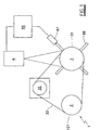
- Figure 1 is a schematic view of the device of the invention;
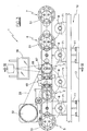
- Figure 2 is a partly sectional view of the device of the invention, taken from above;
- Figure 3 is a section on the line III-III of Figure 2;
- Figure 4 is a cross-section on the line IV-IV of Figure 2; and
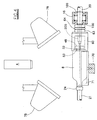
- Figure 5 is an enlargement of a part of the invention shown in Figure 2.
-
- Said figures show the
device 1 for determining the quality of silk-screen printing on bottles of circular cross-section, the device comprising apositioning station 2 preceding the image inspection andacquisition station 3. Above thestation 3 and exactly coaxial with its centre, there is positioned avideo camera 4 as shown in Figures 3 and 4. - The
positioning station 2 andinspection station 3 are respectively preceded and followed byidentical stations - The sole purpose of the
station 5 is to act as a parking station before thebottles 8 are fed to thepositioning station 2, whereas thestations selector device 9. The number of saidstations device 1 of the invention is to be installed, and in fact could be dispensed with in certain embodiments of the invention. - The
device 1 for determining print quality comprises aframe 10 supporting all thestations frame 10 comprises twouprights 11 fixed to thebase 13 and each supporting an internally hollowcylindrical sleeve 14 for receiving arod 15. - With reference to Figures 2 and 5, to the front ends of the two
rods 15 there is fixed abar 16 having a plurality of holes for receivingshafts 50 of thestations shafts stations - In front of the
bar 16 there is provided asecond bar 17 supportingrods bar 16 comprise idly mounted frusto-conical nosepieces 24 arranged to interact with the mouth of the bottle. Therods shafts 50 of thestations rods shafts shafts 50 supportcircular seats 51 arranged to interact with the base of thebottle 8. - Both the
shafts bar 16 by way ofusual ball bearings 100, and are rotated by a usualpneumatic actuator 32, which transmits motion to them via atoothed belt 33 engaging two pulleys, 121 and 131 respectively, mounted on saidshafts pulley 131 is coupled to theshaft 30 by ausual key 34, whereas thepulley 121 does not transmit motion directly to theshaft 20 but is coupled to afrontal clutch device 40. Said device comprises acoupling 41 arranged to engage aflange 42. - The
coupling 41 is fixed to thepulley 21 by ascrew 43, the entire unit being mounted on theshaft 20 by way ofball bearings flange 42 is coupled to theshaft 20 by akey 46. Saidflange 42 can slide longitudinally on theshaft 20 to be positioned in a first position in which it engages thecoupling 41 to rotate theshaft 20, and in a second position in which it is disengaged from saidcoupling 41 but engages thebar 16. The engagement or disengagement of theflange 42 by thecoupling 41 is effected by the operator on the basis of the cross-sectional shape of the bottle to be inspected, as explained hereinafter. - With reference to Figure 5, the
front part shafts bar 16 comprises ablock 48, which is fixed to the end of said shafts and has a central hole for passage of a usual spring-loadedexpeller 49 emerging from the ends of saidshafts retractable pin 52 to be inserted into areference notch 53 present in the bottle, in order to rotate this latter. - It should be noted that said
front parts shafts - An internally hollow cup-
shaped member 60 provided with aninner shoulder 61, known as the endpiece, for receiving the bottle base, is idly mounted on theparts shafts rear shank 62 provided with acircular groove 63 for receiving abelt 64 which prevents or at least brakes any rotation of saidmembers 60 during the rotation of theshafts belt 64 is fixed to thebar 16 by known means. - On the rear end of the
shaft 30 there is rigidly mounted across-shaped member 66, the mutually perpendicular arms of which act as an en countering member for theproximity sensor 67. - The
rods 15 are connected together by arear plate 68, to which there is fixed anarm 69 connected to an assembly of usual means for moving theplates - The
bottles 8 are fed to thestations trays 71 supporting thebottles 8. Between one station and the next thetrays 71 travel through a circumferential arc, as shown in Figure 3. - Finally, the device of the invention comprises within the
station 3 twoidentical spotlights 78 orientated as shown in Figure 5, to illuminate the image acquisition area. - The
device 1 of the invention also comprises acontrol system 99 for controlling its operation, as now described. - Starting from the position shown in Figure 2, the
bars bottles 8 onto theunderlying trays 71, after which theconveyor 70 feeds the bottles to the next station by undergoing forward travel, ie by causing thetrays 71 to travel through a circular arc in an anti-clockwise direction. Specifically, the last tray to the right of theconveyor 70 feeds thebottle 8 to theselector device 9, which supports it by means of thesucker 90. If the bottle is defective, thenozzle 91 blows an air jet against the base of the bottle, which in this manner is urged onto achute 92, whereas if the bottle is free of defects it is withdrawn by usual means, not shown, and fed to the next production cycle. In contrast, thefirst tray 71, to the left of theconveyor 70, which receives the bottle from a usual sucker-type feed device 73, transfers it to thestation 5. - When the bottles are in position in the
stations plates nosepieces 24 and theseats 51 in thestations nosepieces 24 and themembers 60 in thestations - The
conveyor 70 then moves rearwards into its initial position. During this repositioning of theconveyor 70 the control system causes thepneumatic actuator 32 to rotate through 240°, so rotating theshafts - In the
positioning station 2 the bottle is maintained at rest between thenosepiece 24 and thecup 60, while theshaft 20 rotates through 450° to rotate theblock 48 such that theretractable pin 52, while rotating, becomes inserted in thereference notch 53 present in the bottle. When this occurs the bottle is rotated by the shaft as far as its travel limit. In this manner the bottle is preset in a determined known position, so that when the bottle is fed to thenext station 3 for image acquisition and recording, thepin 52, supported by theblock 48 rigid with theshaft 30, becomes directly inserted into the reference notch present in the bottle base in order to rotate it, or at most has to be rotated through only a few degrees to enable it to be inserted in saidreference notch 53. - Simultaneously with the rotation of the
shaft 20, theshaft 30 rotates through 360° to rotate the bottle previously positioned in thestation 2. During the rotation of theshaft 30, when the first of the arms of thecross-shaped member 66 passes in front of theproximity sensor 67, this latter causes thevideo camera 4 to acquire images. The video camera successively acquires one image each time one of the arms of thecross-shaped member 66 passes in front of theproximity sensor 67. - In this manner the video camera acquires four images corresponding to successive 90° rotations of the bottle. The acquired images are then compared with a reference image by suitable software which also causes the
selector device 9 to reject those bottles presenting print imperfections. - When image acquisition is complete the
conveyor 70 feeds the bottles to the next station, thepneumatic actuator 32 simultaneously being made to rotate in the reverse direction to return to its initial position, after which the cycle is repeated identically to the aforedescribed. - If the cross-section through the bottles to be inspected is ellipsoidal, rectangular or square, the
positioning station 2 is no longer required as it is no longer necessary to align the bottle with a determined reference. Consequently theshaft 20 is made idle by disengaging theflange 42 from thecoupling 41 of the frontalclutch device 40, so that rotation of thepulley 21 does not cause theshaft 20 to rotate. - In this case the cup-shaped
members 60 must evidently have a shape which matches the shape of the bottle base, and thebelt 64 which prevents rotation of the cup-shapedmember 60 mounted on theshaft 30 is no longer required. - Again in this case, the
trays 71 are replaced with trays of suitable shape.
Claims (11)
- An automatic device for determining print quality on bottles of circular, elliptical or polygonal cross-section, comprising at least one print quality inspection station in which a cylindrical portion of the image surface is photographed by a camera or video camera, means for transferring the bottle to successive inspection stations in succession, in each of which a further portion of the image is photographed, means for assembling the images acquired in each inspection station to obtain the overall image of all the photographed portions, comparator means for comparing the overall image with a reference image, and means for indicating non-conformity between the overall acquired image and the reference image and for operating an actuator which feeds the object carrying the non-conforming overall image to a rejected object collection line, characterised in that one of the inspection stations (3) comprises means (32, 33, 121, 131, 20, 30, 48, 53) for rotating the image-carrying bottle (8) through an angle of at least 360° with continuity, a single video camera (4) arranged to photograph in succession an image portion after each rotation of the [bottle] image-carrying bottle (8) through an angle equal to 360° divided by the total number of images to be acquired, means for assembling the acquired images to obtain the overall image of all the portions photographed, and comparator means for comparing the overall image with a reference image.
- A device as claimed in claim 1, characterised by comprising a inspection station (3) and, upstream thereof, a positioning station (2), in both of which an idly mounted nosepiece (24) and an idly mounted suitably braked seat (60) aligned with the nosepiece, support the object (8) and are caused to rotate when a locator (48, 52) rotating with continuity within the seat becomes inserted in a notch present in the base of the bottle.
- A device according to claim 2 characterised in that the positioning station and the inspection station are associated with a stepwise conveying line (70) for the bottles, and comprise a first horizontal crosspiece (17) carrying the nosepieces, a second crosspiece (16) parallel to the first and carrying the seats aligned with said nosepieces, means (69) for moving said two crosspieces towards and away from each other at each step of the conveying line, said seats comprising the rotating locator in their interior, said rotating locators being connected to a single motor (32).
- A device as claimed in claim 2, characterised in that the rotating locator of the positioning station is made to rotate through an angle greater than 360°.
- A device as claimed in claim 2 characterised in that the rotating locator of the positioning station is made to rotate through an angle of 450°.
- A device as claimed in claim 2, characterised in that the rotating locator of the inspecting station is made to undergo continuous rotations of close to 360° overall.
- A device as claimed in claim 2 characterised in that the rotating locator of the inspection station is associated with an encountering member (66) having at least two radial arms which interfere in succession with a proximity sensor (67) arranged to control the activation of the video camera.
- A device as claimed in claim 2 characterised by comprising a single motor (32) which by way of a transmission rotates the rotating locators present within the seat of the positioning station and within the seat of the inspection station.
- A device as claimed in claim 7, characterised in that the locator rotating within the seat of the positioning station is associated to means (42, 43) for disengage it from the drive motor (32).
- A device as claimed in claim 7, characterised in that the locator rotating within the seat of the positioning station is connected to its transmission via a disengageable clutch.
- A device as claimed in claim 1 characterised by comprising at least one spotlight (78), of which the axes in the vertical plane converge onto the image to be photographed.
Applications Claiming Priority (2)
| Application Number | Priority Date | Filing Date | Title |
|---|---|---|---|
| ITRE980104 | 1998-10-22 | ||
| IT1998RE000104A IT1305329B1 (en) | 1998-10-22 | 1998-10-22 | AUTOMATIC QUALITY DETECTION DEVICE FOR PRINTING SUFLACONS OR BOTTLES OF ANY SHAPE |
Publications (2)
| Publication Number | Publication Date |
|---|---|
| EP0999047A1 EP0999047A1 (en) | 2000-05-10 |
| EP0999047B1 true EP0999047B1 (en) | 2004-08-11 |
Family
ID=11399309
Family Applications (1)
| Application Number | Title | Priority Date | Filing Date |
|---|---|---|---|
| EP99203018A Expired - Lifetime EP0999047B1 (en) | 1998-10-22 | 1999-09-16 | Automatic device for determining print quality on bottles of any shape |
Country Status (7)
| Country | Link |
|---|---|
| US (1) | US6184988B1 (en) |
| EP (1) | EP0999047B1 (en) |
| AT (1) | ATE273134T1 (en) |
| CA (1) | CA2282244C (en) |
| DE (1) | DE69919297T2 (en) |
| ES (1) | ES2224546T3 (en) |
| IT (1) | IT1305329B1 (en) |
Families Citing this family (15)
| Publication number | Priority date | Publication date | Assignee | Title |
|---|---|---|---|---|
| GB2402796B (en) * | 2003-06-12 | 2005-04-20 | Phasor Ltd | A method and device for identifying information on the surface of an article |
| NL1025332C2 (en) * | 2004-01-27 | 2005-08-02 | Heineken Tech Services | Device and method for detecting contamination in a container. |
| US7060999B2 (en) | 2004-07-09 | 2006-06-13 | Owens-Brockway Glass Container Inc. | Apparatus and method for inspecting ribbed containers |
| FR2891194B1 (en) * | 2005-09-28 | 2007-11-30 | Cer Soc Par Actions Simplifiee | MACHINE FOR MARKING A CYLINDRICAL OBJECT AND METHODS USED WITH SUCH A MACHINE |
| FR2897555B1 (en) * | 2006-02-21 | 2008-04-18 | Cer Soc Par Actions Simplifiee | MACHINE AND METHOD FOR MARKING SHAPE PIECES |
| US9025831B2 (en) * | 2009-11-10 | 2015-05-05 | Monsanto Technology Llc | Apparatus and methods for automated phenotypic screening of plant genotypes |
| US9555616B2 (en) | 2013-06-11 | 2017-01-31 | Ball Corporation | Variable printing process using soft secondary plates and specialty inks |
| PL3028856T3 (en) | 2014-12-04 | 2019-10-31 | Ball Beverage Packaging Europe Ltd | Printing apparatus |
| CN105842258A (en) * | 2016-05-18 | 2016-08-10 | 白杨 | Appearance and size detecting device of bottle jacking station |
| US10549921B2 (en) | 2016-05-19 | 2020-02-04 | Rexam Beverage Can Company | Beverage container body decorator inspection apparatus |
| US11034145B2 (en) | 2016-07-20 | 2021-06-15 | Ball Corporation | System and method for monitoring and adjusting a decorator for containers |
| RU2701243C1 (en) | 2016-07-20 | 2019-09-25 | Бол Корпорейшн | System and method of adjusting paint assembly of printing machine on cylinders and tubes |
| CA3088534C (en) | 2018-01-19 | 2023-03-14 | Ball Corporation | System and method for monitoring and adjusting a decorator for containers |
| CN110434860B (en) * | 2019-07-04 | 2022-08-16 | 佛山科学技术学院 | Robot automatic spraying method and device |
| DE102023119491A1 (en) * | 2023-07-24 | 2025-01-30 | ibea Ingenieurbüro für Elektronik und Automatisation GmbH | Method and device for inspecting at least one outer surface of containers |
Family Cites Families (2)
| Publication number | Priority date | Publication date | Assignee | Title |
|---|---|---|---|---|
| IT1246543B (en) * | 1991-05-03 | 1994-11-24 | Moss Srl | MACHINE TO PRINT THE OUTSIDE LATERAL SURFACE OF CONTAINERS IN GENERAL IN SERIGRAPHY. |
| DE19614740A1 (en) * | 1996-04-15 | 1997-10-16 | Kammann Maschf Werner | Method and device for printing self-supporting individual objects |
-
1998
- 1998-10-22 IT IT1998RE000104A patent/IT1305329B1/en active
-
1999
- 1999-09-15 CA CA002282244A patent/CA2282244C/en not_active Expired - Fee Related
- 1999-09-16 AT AT99203018T patent/ATE273134T1/en active
- 1999-09-16 EP EP99203018A patent/EP0999047B1/en not_active Expired - Lifetime
- 1999-09-16 DE DE69919297T patent/DE69919297T2/en not_active Expired - Lifetime
- 1999-09-16 ES ES99203018T patent/ES2224546T3/en not_active Expired - Lifetime
- 1999-09-29 US US09/407,886 patent/US6184988B1/en not_active Expired - Lifetime
Also Published As
| Publication number | Publication date |
|---|---|
| IT1305329B1 (en) | 2001-05-04 |
| US6184988B1 (en) | 2001-02-06 |
| DE69919297T2 (en) | 2004-12-23 |
| ATE273134T1 (en) | 2004-08-15 |
| CA2282244C (en) | 2009-09-08 |
| CA2282244A1 (en) | 2000-04-22 |
| EP0999047A1 (en) | 2000-05-10 |
| ITRE980104A1 (en) | 2000-04-22 |
| ES2224546T3 (en) | 2005-03-01 |
| DE69919297D1 (en) | 2004-09-16 |
Similar Documents
| Publication | Publication Date | Title |
|---|---|---|
| CA2282244C (en) | Automatic device for determining print quality on bottles of any shape | |
| US3923158A (en) | On-line multistation inspection device for machine moulded products | |
| CN112229844B (en) | Workpiece surface defect detection equipment | |
| CN112722798B (en) | Bullet delivery device | |
| CN107877139B (en) | Eccentric bearing eccentricity image alignment and press fitting system | |
| CN112858342B (en) | Transparent box body fully automatic image defect detection device | |
| JP2022538614A (en) | Device for optical inspection of preforms | |
| CN213181299U (en) | Automatic detection device of display screen | |
| CN115388958B (en) | Multifunctional empty bottle quality online detection system and method based on machine vision | |
| KR20220056094A (en) | Pipe bolt inspection device with position alignment | |
| CN212301277U (en) | Full-automatic visual detection system for appearance of silk ingots | |
| CN114101079A (en) | Cylindrical shell detection equipment | |
| KR102365598B1 (en) | Capsule inspection device | |
| CN108760762B (en) | Full-automatic intelligent lamp inspection equipment | |
| CN110947635A (en) | Bearing inner race surface defect automatic checkout device | |
| CN116519701A (en) | A kind of column product detection machine and detection method | |
| CN213764756U (en) | Bearing assembling machine | |
| CN223727719U (en) | Packaging bottle defect detection equipment | |
| CN223642309U (en) | A smart visual inspection device for quality defects in glass bottles | |
| CN211652577U (en) | Rubber sleeve defect identification and detection system | |
| CN114083778A (en) | Bottle and bottle blank removing mechanism and operation method thereof | |
| CN116022523A (en) | Carrier and detection device therewith | |
| CN219541018U (en) | Image quality inspection device | |
| CN218766673U (en) | Bottle appearance detector | |
| CN220005001U (en) | Milk glass bottle bottleneck breach detection device |
Legal Events
| Date | Code | Title | Description |
|---|---|---|---|
| PUAI | Public reference made under article 153(3) epc to a published international application that has entered the european phase |
Free format text: ORIGINAL CODE: 0009012 |
|
| AK | Designated contracting states |
Kind code of ref document: A1 Designated state(s): AT BE CH CY DE DK ES FI FR GB GR IE IT LI LU MC NL PT SE |
|
| AX | Request for extension of the european patent |
Free format text: AL;LT;LV;MK;RO;SI |
|
| 17P | Request for examination filed |
Effective date: 20000726 |
|
| AKX | Designation fees paid |
Free format text: AT BE CH CY DE DK ES FI FR GB GR IE IT LI LU MC NL PT SE |
|
| 17Q | First examination report despatched |
Effective date: 20030311 |
|
| GRAP | Despatch of communication of intention to grant a patent |
Free format text: ORIGINAL CODE: EPIDOSNIGR1 |
|
| GRAS | Grant fee paid |
Free format text: ORIGINAL CODE: EPIDOSNIGR3 |
|
| GRAA | (expected) grant |
Free format text: ORIGINAL CODE: 0009210 |
|
| AK | Designated contracting states |
Kind code of ref document: B1 Designated state(s): AT BE CH CY DE DK ES FI FR GB GR IE IT LI LU MC NL PT SE |
|
| PG25 | Lapsed in a contracting state [announced via postgrant information from national office to epo] |
Ref country code: FI Free format text: LAPSE BECAUSE OF FAILURE TO SUBMIT A TRANSLATION OF THE DESCRIPTION OR TO PAY THE FEE WITHIN THE PRESCRIBED TIME-LIMIT Effective date: 20040811 Ref country code: CY Free format text: LAPSE BECAUSE OF FAILURE TO SUBMIT A TRANSLATION OF THE DESCRIPTION OR TO PAY THE FEE WITHIN THE PRESCRIBED TIME-LIMIT Effective date: 20040811 Ref country code: BE Free format text: LAPSE BECAUSE OF FAILURE TO SUBMIT A TRANSLATION OF THE DESCRIPTION OR TO PAY THE FEE WITHIN THE PRESCRIBED TIME-LIMIT Effective date: 20040811 |
|
| REG | Reference to a national code |
Ref country code: GB Ref legal event code: FG4D |
|
| REG | Reference to a national code |
Ref country code: CH Ref legal event code: NV Representative=s name: ISLER & PEDRAZZINI AG Ref country code: CH Ref legal event code: EP |
|
| REG | Reference to a national code |
Ref country code: IE Ref legal event code: FG4D |
|
| PG25 | Lapsed in a contracting state [announced via postgrant information from national office to epo] |
Ref country code: LU Free format text: LAPSE BECAUSE OF NON-PAYMENT OF DUE FEES Effective date: 20040916 |
|
| REF | Corresponds to: |
Ref document number: 69919297 Country of ref document: DE Date of ref document: 20040916 Kind code of ref document: P |
|
| PG25 | Lapsed in a contracting state [announced via postgrant information from national office to epo] |
Ref country code: MC Free format text: LAPSE BECAUSE OF NON-PAYMENT OF DUE FEES Effective date: 20040930 |
|
| PG25 | Lapsed in a contracting state [announced via postgrant information from national office to epo] |
Ref country code: SE Free format text: LAPSE BECAUSE OF FAILURE TO SUBMIT A TRANSLATION OF THE DESCRIPTION OR TO PAY THE FEE WITHIN THE PRESCRIBED TIME-LIMIT Effective date: 20041111 Ref country code: GR Free format text: LAPSE BECAUSE OF FAILURE TO SUBMIT A TRANSLATION OF THE DESCRIPTION OR TO PAY THE FEE WITHIN THE PRESCRIBED TIME-LIMIT Effective date: 20041111 Ref country code: DK Free format text: LAPSE BECAUSE OF FAILURE TO SUBMIT A TRANSLATION OF THE DESCRIPTION OR TO PAY THE FEE WITHIN THE PRESCRIBED TIME-LIMIT Effective date: 20041111 |
|
| ET | Fr: translation filed | ||
| REG | Reference to a national code |
Ref country code: ES Ref legal event code: FG2A Ref document number: 2224546 Country of ref document: ES Kind code of ref document: T3 |
|
| PLBE | No opposition filed within time limit |
Free format text: ORIGINAL CODE: 0009261 |
|
| STAA | Information on the status of an ep patent application or granted ep patent |
Free format text: STATUS: NO OPPOSITION FILED WITHIN TIME LIMIT |
|
| 26N | No opposition filed |
Effective date: 20050512 |
|
| REG | Reference to a national code |
Ref country code: CH Ref legal event code: PCAR Free format text: ISLER & PEDRAZZINI AG;POSTFACH 1772;8027 ZUERICH (CH) |
|
| PG25 | Lapsed in a contracting state [announced via postgrant information from national office to epo] |
Ref country code: PT Free format text: LAPSE BECAUSE OF NON-PAYMENT OF DUE FEES Effective date: 20050111 |
|
| PGFP | Annual fee paid to national office [announced via postgrant information from national office to epo] |
Ref country code: IE Payment date: 20100723 Year of fee payment: 12 Ref country code: ES Payment date: 20100730 Year of fee payment: 12 |
|
| PGFP | Annual fee paid to national office [announced via postgrant information from national office to epo] |
Ref country code: IT Payment date: 20100728 Year of fee payment: 12 Ref country code: FR Payment date: 20100818 Year of fee payment: 12 Ref country code: AT Payment date: 20100902 Year of fee payment: 12 |
|
| PGFP | Annual fee paid to national office [announced via postgrant information from national office to epo] |
Ref country code: GB Payment date: 20100927 Year of fee payment: 12 |
|
| PGFP | Annual fee paid to national office [announced via postgrant information from national office to epo] |
Ref country code: NL Payment date: 20100929 Year of fee payment: 12 |
|
| PGFP | Annual fee paid to national office [announced via postgrant information from national office to epo] |
Ref country code: DE Payment date: 20100921 Year of fee payment: 12 Ref country code: CH Payment date: 20101007 Year of fee payment: 12 |
|
| REG | Reference to a national code |
Ref country code: NL Ref legal event code: V1 Effective date: 20120401 |
|
| REG | Reference to a national code |
Ref country code: CH Ref legal event code: PL |
|
| GBPC | Gb: european patent ceased through non-payment of renewal fee |
Effective date: 20110916 |
|
| PG25 | Lapsed in a contracting state [announced via postgrant information from national office to epo] |
Ref country code: IT Free format text: LAPSE BECAUSE OF NON-PAYMENT OF DUE FEES Effective date: 20110916 |
|
| REG | Reference to a national code |
Ref country code: IE Ref legal event code: MM4A |
|
| REG | Reference to a national code |
Ref country code: FR Ref legal event code: ST Effective date: 20120531 |
|
| REG | Reference to a national code |
Ref country code: DE Ref legal event code: R119 Ref document number: 69919297 Country of ref document: DE Effective date: 20120403 |
|
| PG25 | Lapsed in a contracting state [announced via postgrant information from national office to epo] |
Ref country code: DE Free format text: LAPSE BECAUSE OF NON-PAYMENT OF DUE FEES Effective date: 20120403 Ref country code: IE Free format text: LAPSE BECAUSE OF NON-PAYMENT OF DUE FEES Effective date: 20110916 Ref country code: LI Free format text: LAPSE BECAUSE OF NON-PAYMENT OF DUE FEES Effective date: 20110930 Ref country code: NL Free format text: LAPSE BECAUSE OF NON-PAYMENT OF DUE FEES Effective date: 20120401 Ref country code: CH Free format text: LAPSE BECAUSE OF NON-PAYMENT OF DUE FEES Effective date: 20110930 |
|
| PG25 | Lapsed in a contracting state [announced via postgrant information from national office to epo] |
Ref country code: FR Free format text: LAPSE BECAUSE OF NON-PAYMENT OF DUE FEES Effective date: 20110930 Ref country code: GB Free format text: LAPSE BECAUSE OF NON-PAYMENT OF DUE FEES Effective date: 20110916 |
|
| REG | Reference to a national code |
Ref country code: AT Ref legal event code: MM01 Ref document number: 273134 Country of ref document: AT Kind code of ref document: T Effective date: 20110916 |
|
| PG25 | Lapsed in a contracting state [announced via postgrant information from national office to epo] |
Ref country code: AT Free format text: LAPSE BECAUSE OF NON-PAYMENT OF DUE FEES Effective date: 20110916 |
|
| REG | Reference to a national code |
Ref country code: ES Ref legal event code: FD2A Effective date: 20130417 |
|
| PG25 | Lapsed in a contracting state [announced via postgrant information from national office to epo] |
Ref country code: ES Free format text: LAPSE BECAUSE OF NON-PAYMENT OF DUE FEES Effective date: 20110917 |