EP0998994A2 - Multi-wall tube - Google Patents
Multi-wall tube Download PDFInfo
- Publication number
- EP0998994A2 EP0998994A2 EP99308170A EP99308170A EP0998994A2 EP 0998994 A2 EP0998994 A2 EP 0998994A2 EP 99308170 A EP99308170 A EP 99308170A EP 99308170 A EP99308170 A EP 99308170A EP 0998994 A2 EP0998994 A2 EP 0998994A2
- Authority
- EP
- European Patent Office
- Prior art keywords
- tube
- layer
- metal
- core tube
- metal strip
- Prior art date
- Legal status (The legal status is an assumption and is not a legal conclusion. Google has not performed a legal analysis and makes no representation as to the accuracy of the status listed.)
- Withdrawn
Links
Images

Classifications
-
- B—PERFORMING OPERATIONS; TRANSPORTING
- B21—MECHANICAL METAL-WORKING WITHOUT ESSENTIALLY REMOVING MATERIAL; PUNCHING METAL
- B21D—WORKING OR PROCESSING OF SHEET METAL OR METAL TUBES, RODS OR PROFILES WITHOUT ESSENTIALLY REMOVING MATERIAL; PUNCHING METAL
- B21D3/00—Straightening or restoring form of metal rods, metal tubes, metal profiles, or specific articles made therefrom, whether or not in combination with sheet metal parts
-
- B—PERFORMING OPERATIONS; TRANSPORTING
- B21—MECHANICAL METAL-WORKING WITHOUT ESSENTIALLY REMOVING MATERIAL; PUNCHING METAL
- B21C—MANUFACTURE OF METAL SHEETS, WIRE, RODS, TUBES, PROFILES OR LIKE SEMI-MANUFACTURED PRODUCTS OTHERWISE THAN BY ROLLING; AUXILIARY OPERATIONS USED IN CONNECTION WITH METAL-WORKING WITHOUT ESSENTIALLY REMOVING MATERIAL
- B21C37/00—Manufacture of metal sheets, rods, wire, tubes, profiles or like semi-manufactured products, not otherwise provided for; Manufacture of tubes of special shape
- B21C37/06—Manufacture of metal sheets, rods, wire, tubes, profiles or like semi-manufactured products, not otherwise provided for; Manufacture of tubes of special shape of tubes or metal hoses; Combined procedures for making tubes, e.g. for making multi-wall tubes
- B21C37/08—Making tubes with welded or soldered seams
- B21C37/09—Making tubes with welded or soldered seams of coated strip material ; Making multi-wall tubes
Definitions
- the present invention relates to a method of making multi-wall metal tube and to the resultant tube. More particularly it relates to multi-wall metal tubing produced in a continuous process from precut metal strip.
- U.S. Patent No. 1,431,368 to Bundy entitled “Tubing” discloses a multi-wall metal tube formed of metal strip that has been tinned or painted with solder and then longitudinally wrapped around a stationary mandrel to form a multi-wall tube.
- the mandrel is used to support the tube at its inside diameter at a finishing stand. This mandrel assures a tight tube construction and size tolerance control.
- the process of the Bundy patent has represented the industry standard for over forty year, an opportunity for improvement has been noted with a resultant tube that is considered at least equal to that currently used.
- the mandrel at the finishing station is a source of continuous concern, and its maintenance a substantial cost factor.
- the present invention represents an improvement of the prior art process by elimination of the mandrel.
- the finished multi-layer tube is also considered new to the art.
- the present invention is directed to a method for making multi-wall metal tube and to the resultant tube.
- a preformed tube is used as an inner core.
- a metal strip, coated with binding metal, is longitudinally wrapped around the core tube.
- the assemblage is then heated to the brazing temperature of the binding metal whereby all layers become integral to form the finished multi-wall tube.
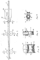
- the method of the present invention employs an in-line processing mill as illustrated in Fig. 1.
- an inner core tube 12 and a metal strip or wrap coated with binding metals 16 are supplied simultaneously tote in-line processing mill.
- the coated metal wrap 18 passes through a first set of rollers 20 and 22 which puts a shoulder portion in the coated metal wrap.
- a second set of rollers 26 and 28 curl the edges of the coated metal wrap up.
- a third set of rollers 30 and 32 press the coated metal wrap in an overlapping relation around the inner core tube 12.
- the assemblage 34 of the inner core tube 12 and coated wrap 18 is then fed either continuously, or in batches, into a furnace 36 held at the brazing temperature of the binding metal 16. Brazing causes all layers to become integral.
- the multi-wall tube of the present invention is a multi-wall tube 10 comprising an inner core tube 12 and an outer strip or wrap 18 brazed to the inner core tube 12.
- the inner core tube 12 in itself is pressure tight independent of the outer wrap 18. Due to variability within the manufacturing process, the seam of the outer wrap 18 may be loose or has voids present. Without a pressure tight inner core tube 12 present, the loose outer seam would be a source of leakage.
- a flare is a radially enlarged flange at the end of a tube for connection with a mating component.
- a flare is formed by hitting the end of the tube with at least one punch, while the tube is situated in a clamp block. The clamp block and punch are both machined to produce the appropriate flare size and shape.
- a single flare is formed with one hit by a single punch.
- a double flare requires two hits by two different punches. To form a double flare, the first hit by the first punch forms a variation of the front bead. The second hit by the second punch folds the tube inwardly and coins the appropriate angle on the flare sealing surface.
- stresses are formed at the end of the flare and the fold section of the double flare. These stress areas have potential for seam separation and creates a source of leakage.
- a mandrel is necessary to support the outer layer at inside diameter at the finishing stand.
- the mandrel remains stationary while a continuously moving metal stock is wrapped around the stationary mandrel.
- Lubrication between the stationary mandrel and the moving metal stock is therefore necessary to reduce the friction between the mandrel and the metal stock.
- a by-product of the mandrel process is the remains of the lubrication in the inside diameter of the finished multi-wall tube 10.
- the use of an inner core tube 12, in place of a mandrel, to support the tube at its inside diameter during the formation of the outer wall layers eliminates the inside diameter cleanliness issue since little, or possibly no, lubricant is required in the process.
- the inner core tube 12, defining the inside diameter of the multi-wall tube 10 is formed during a separate process from the in-line process mill. The cleanliness of the of inside diameter is then independent of the in-line process mill, but rather is dependent on the formation of the inner core tube 12. As long as inner core tube is formed in such a manner that its inside diameter is clean, the inside diameter of the multi-wall tube 10 would likewise be clean.
- an inner core tube 12 in place of a mandrel also eliminates the downtime required for changing the mandrel.
- lubricants are used between the mandrel and the metal stock to reduce friction, wear on the mandrel still occurs. Once wear reduces the diameter of the mandrel, the inside diameter of the tube is also reduced. As a result, the difference between the inside diameter and the outer diameter is increased allowing the seam to have voids or looseness. Since voids or looseness in the seams are highly undesirable, the mandrel would need to be changed on a periodic basis creating downtime in the process.
- the present invention does not use a stationary mandrel, rather, an inner core is fed at the same rate as the metal stock for forming the outer layer. Hence, downtimes for changing worn mandrels are eliminated.
- Another advantage of using an inner core tube in place of a mandrel is the elimination of the step of applying a carbon lacquer on the assemblage prior to the heating stage. If the resultant tube were not supported on either side, upon heating the assemblage to the brazing temperature of the binding metal, the binding metal would run off from the seam and the assemblage would have a tendency to unwrap. To prevent the binding metal from running off, a carbon lacquer is applied to the assemblage prior to the heating process. The carbon lacquer has a similar effect as oxidizing the binding metal and solidifies the binding metal. In addition, due to the dark color of the carbon lacquer, it also creates a black body effect allowing the resultant tube to absorb heat more quickly and evenly.
- a tube having a permanent inner core tube, in place of a mandrel for forming the outer tube, would eliminate the problems associated with the tube unwrapping and the need for the black body effect.
- the metal wrap 18 is supported at the inside diameter by the inner tube 12; hence, the tendency for the metal wrap 18 to unwrap during the heating stage is reduced.
- a process using an inner tube does not need to absorb as much heat since the process is more forgiving due the metal wrap 18 supported at the inner diameter by the inner core tube 12. With the temperature for the heating process lower for the present invention than for a process without an inner core tube, the temperature in the furnace would not be high enough to cause the binding metal 12 to run off.
- Suitable tubes to form inner core tube 12 include single wall welded steel tube, single wall welded stainless steel tube, single wall seamless steel tube, single wall seamless stainless steel tube, brazed double wall tube or multi-wall tube of various constructs described herein.
- the inner core tube 12 may be produced by conventional tube forming method. The particular process used for forming the inner core tube 12 is not a part of this invention.
- the formed inner core 12 can be fed to the outer wall tube forming mill in a continuous integrated line immediately after the formation of the inner core tube. Alternatively, the formed inner core tube 12 can be accumulated in a coiled form and then later fed to the outer layer forming mill.
- a side view of the forming mill is shown on Figure 1.
- Metal strip or wrap 18 is shown in Fig. 2. It is cut to appropriate width and coated with a binding metal 16 on both sides. Suitable binding metals 16 include copper, nickel, silver braze alloy or any combinations of these metals.
- the metal wrap 18, coated with binding metal 16, is fed continuously to the in-line processing mill at the same rate as the inner core tube 12 is being fed to the in-line processing mill.
- metal wrap 18 passes between the upper roll 20 and lower roll 22 which puts a shoulder portion 24 in the metal stock as shown on Fig. 3. Shoulder 24 is offset to one side of the center of the metal wrap 18 such that one side of the wrap is wider than the other side. This allows the wider side to curl over the narrower portion of the wrap.
- the metal wrap 18 reaches rolls 26 and 28 which serve to curl the edges of the metal wrap up as shown on Fig. 4.
- the metal wrap 18 then passes around the core tube 12 and a set of horizontally-disposed pressure rolls 30 and 32 serve to press the metal wrap 18 in overlapped relation around the core tube 12 as shown on Fig. 5.
- the assemblage 34 comprising the inner core tube 12 longitudinally wrapped with metal wrap 18, is then fed continuously into in a furnace 36 to the brazing temperature of the binding metal 16, whereby all layers become integral to complete the multi-wall product of the present invention.
- the details of the brazing process are conventional and well known.
- the assemblage 34 can be batch processed by cutting it into 60 to 100 feet length sections after the metal wrap 18 is wrapped around the core tube 12. The cut sections of the assemblage 34 are then batch heated in a furnace to the brazing temperature of the binding metal 16.
- FIG. 6 A cross-section view of the finished multi-layer tube product 10 is shown in FIG. 6.
- the multi-layer tube 10 comprises an inner core tube 12, a metal wrap 18 wrapped around the inner tube 12 and a binding layer 16a between the inner core 12 and the metal wrap 18. Located between the metal wrap 18 is another binding metal layer 16b.
- the tube differs from prior tubes because it has extra layers construction. Alternatively, the strip could be narrower and only wrapped around once or the strip can be wider and wrapped around three times.
- Yet another variation of the present invention comprise using a double-wall tube as the core material rather than a single wall tube.
- the inner core tube 12 is pressure tight and the metal wrap 18 is not critical to the leak integrity of the multi-walled tube 10.
- a double-wall tube is used in place of a single wall tube as the core tube.
- the above embodiment is for the formation of metal strip 18 having two layers.
- the metal strip 18 can be formed of a single layer or the metal strip 18 can be formed of three or more layers.
Landscapes
- Engineering & Computer Science (AREA)
- Mechanical Engineering (AREA)
- Rigid Pipes And Flexible Pipes (AREA)
- Laminated Bodies (AREA)
Abstract
Description
Claims (19)
- A multi-layer metal tube comprising:an inner core tube having an outer cylindrical surface;a strip of metal having an inner cylindrical surface coated with brazing material;
wherein said metal strip is longitudinally wrapped at least once around said core tube and brazed thereto to form an integral tube. - A multi-layer metal tube according to Claim 1 wherein the brazing material connects at least the inner surface of said strip to said outer cylindrical surface of said inner core tube.
- A multi-layer tube as claimed in claim 1 wherein said metal strip is longitudinally wrapped twice around said core tube.
- A multi-layer tube as claimed in claim 1 wherein said metal strip is longitudinally wrapped three times around said core tube.
- A multi-layer tube as claimed in claim 1 wherein said inner core tube has pressure tight integrity.
- A multi-layer tube as claimed in claim 5 wherein said core tube is selected from a group consisting of single wall welded steel tube, single wall welded stainless steel tube, single wall seamless steel tube, single wall seamless stainless steel tube, brazed double wall tube or multi-wall tube.
- A multi-layer tube as claimed in claim 1 wherein said binding metal is selected from a group consisting of copper, nickel, silver braze alloy or any combinations of these.
- A multi-layer tube comprised of:an inner core tube;a metal strip wrapped around the tube;a layer of binding metal between said inner core tube and said wrapped metal strip.
- A multi-layer tube as claimed in claim 8 wherein said metal strip overlaps itself at least once.
- A multi-layer tube as claimed in claim 8 wherein said metal strip overlaps itself at least twice.
- A multi-layer tube as claimed in claim 8 wherein said inner core tube has pressure tight integrity.
- A multi-layer tube as claimed in claim 11 wherein said core tube is selected from a group consisting of single wall welded steel tube, single wall welded stainless steel tube, single wall seamless steel tube, single wall seamless stainless steel tube, brazed double wall tube or multi-wall tube.
- A multi-layer tube as claimed in claim 8 wherein said binding metal is selected from a group consisting of copper, nickel, silver braze alloy or any combinations of these.
- A method of manufacturing a multi-layer tube comprising the steps of:(a) providing an inner core tube;(b) providing a metal strip coated on at least one side with binding metal suitable for brazing;(c) wrapping said metal strip at least once longitudinally around said core tube;(d) heating said inner core tube wrapped with said metal strip to brazing temperature of said binding metal whereby all layers would become integral.
- A method of manufacturing a multi-layer tube as claimed in claim 14 wherein said core tube has pressure tight integrity.
- A method of manufacturing a multi-layer tube as claimed in claim 15 wherein said core tube is selected from a group consisting of single wall welded steel tube, single wall welded stainless steel tube, single wall seamless steel tube, single wall seamless stainless steel tube, brazed double wall tube or multi-wall tube.
- A method of manufacturing a multi-layer tube as claimed in claim 14 wherein said binding material is selected from a group consisting of copper, nickel, silver braze alloy or any combinations of these.
- A method of manufacturing a multi-layer tube as claimed in claim 14 wherein said metal strip is longitudinally wrapped twice around said core tube.
- A method of manufacturing a multi-layer tube as claimed in claim 14 wherein said metal strip is longitudinally wrapped three times around said core tube.
Applications Claiming Priority (2)
| Application Number | Priority Date | Filing Date | Title |
|---|---|---|---|
| US09/181,627 US6092556A (en) | 1998-10-28 | 1998-10-28 | Multi-wall tube |
| US181627 | 1998-10-28 |
Publications (2)
| Publication Number | Publication Date |
|---|---|
| EP0998994A2 true EP0998994A2 (en) | 2000-05-10 |
| EP0998994A3 EP0998994A3 (en) | 2001-06-06 |
Family
ID=22665085
Family Applications (1)
| Application Number | Title | Priority Date | Filing Date |
|---|---|---|---|
| EP99308170A Withdrawn EP0998994A3 (en) | 1998-10-28 | 1999-10-18 | Multi-wall tube |
Country Status (8)
| Country | Link |
|---|---|
| US (1) | US6092556A (en) |
| EP (1) | EP0998994A3 (en) |
| JP (1) | JP2000130651A (en) |
| KR (1) | KR20000029325A (en) |
| CN (1) | CN1252505A (en) |
| AU (1) | AU751221B2 (en) |
| BR (1) | BR9905135A (en) |
| CA (1) | CA2282143A1 (en) |
Cited By (2)
| Publication number | Priority date | Publication date | Assignee | Title |
|---|---|---|---|---|
| EP2602032A1 (en) | 2011-12-09 | 2013-06-12 | Benteler Deutschland GmbH | Method for producing a multilayer metal tube and multilayer metal tube produced accordingly |
| CN103372579A (en) * | 2012-04-20 | 2013-10-30 | 常熟市异型钢管有限公司 | Manufacturing process of aluminum-steel composite pipe with high thermal conductivity for petrochemical |
Families Citing this family (20)
| Publication number | Priority date | Publication date | Assignee | Title |
|---|---|---|---|---|
| US6746715B1 (en) | 2000-06-29 | 2004-06-08 | Wilfried J Schmitz | Method for creation of a multi-walled liquid storage vessel |
| EP1433544B1 (en) | 2000-08-18 | 2008-02-13 | TI Group Automotive Systems Limited | Method for plating a metal strip for use when manufacturing a multiple walled tube |
| CN1900575A (en) * | 2001-02-02 | 2007-01-24 | 三菱重工业株式会社 | Integrated piping plate, machining method for same, machining apparatus for same, and machining equipment for same |
| ITAR20020023A1 (en) | 2002-06-25 | 2003-12-29 | Orocinque S P A | PROCEDURE FOR THE PRODUCTION OF ANIMATED WIRE OR PLATE FOR THE PRODUCTION OF TWO-COLOR ORNAMENTAL ITEMS AND ARTICLES SO MADE |
| CN1311925C (en) * | 2003-12-22 | 2007-04-25 | 吉欣(英德)热轧不锈复合钢有限公司 | Method for manufacturing metal compound pipe by braze welding, hot rolling and continuous welding |
| DE102004028020A1 (en) * | 2004-06-08 | 2005-12-29 | ITT Manufacturing Enterprises, Inc., Wilmington | Multi-walled pipe and process for its production |
| CN101357389B (en) * | 2008-09-25 | 2010-06-23 | 武汉金牛经济发展有限公司 | Novel plastic aluminum steady-state tube alclad forming device |
| DE102011016170A1 (en) * | 2011-04-05 | 2012-10-11 | Faurecia Emissions Control Technologies, Germany Gmbh | Exhaust gas device and method for its production |
| WO2015017095A2 (en) | 2013-07-09 | 2015-02-05 | United Technologies Corporation | Plated polymer nosecone |
| US11691388B2 (en) | 2013-07-09 | 2023-07-04 | Raytheon Technologies Corporation | Metal-encapsulated polymeric article |
| CA2917884A1 (en) | 2013-07-09 | 2015-01-15 | United Technologies Corporation | Plated polymer fan |
| EP3019723A4 (en) | 2013-07-09 | 2017-05-10 | United Technologies Corporation | Plated polymer compressor |
| EP3019722B1 (en) * | 2013-07-09 | 2018-11-21 | United Technologies Corporation | Plated polymer components for a gas turbine engine |
| JP5749305B2 (en) * | 2013-09-03 | 2015-07-15 | 三桜工業株式会社 | Heat transfer tube, heat transfer tube manufacturing method, and heat exchanger |
| CN105312900B (en) * | 2014-05-30 | 2019-04-23 | 万向荣 | A kind of assembly line producing the flat pipe of telescopic scrolling |
| CN108406323B (en) * | 2016-07-16 | 2019-08-02 | 南通北外滩建设工程有限公司 | A kind of inner wall of the pipe integral intelligent processing equipment |
| CN107639989A (en) * | 2017-09-26 | 2018-01-30 | 浙江美力科技股份有限公司 | A kind of tubing and hollow stabilizing rod by light sheet material roll-forming |
| CN108679320A (en) * | 2018-08-22 | 2018-10-19 | 江苏众信绿色管业科技有限公司 | A kind of Covered with Angles enhancing stainless steel tube and its manufacturing method |
| CN110961811A (en) * | 2018-09-29 | 2020-04-07 | 宝山钢铁股份有限公司 | A kind of composite pipe manufacturing method |
| CN113026627B (en) * | 2021-04-09 | 2022-11-11 | 北京琅珑科技有限公司 | Equipment of cleaing away to inside thing of sunken type guardrail stand |
Family Cites Families (9)
| Publication number | Priority date | Publication date | Assignee | Title |
|---|---|---|---|---|
| GB1478962A (en) * | 1973-06-06 | 1977-07-06 | Yorkshire Imperial Metals Ltd | Composite metal elongate product |
| DE2706380C3 (en) * | 1977-02-15 | 1980-05-29 | Institut Elektrosvarki Imeni E.O. Patona Akademii Nauk Ukrainskoj Ssr, Kiew (Sowjetunion) | Method of making multilayer casings |
| JPS6054123B2 (en) * | 1977-07-21 | 1985-11-28 | 臼井国際産業株式会社 | Method for manufacturing a small diameter metal polymer tube using a double-wound tube as the outer tube |
| NO165612C (en) * | 1984-06-20 | 1991-03-06 | Furukawa Electric Co Ltd | FLEXIBLE COMPOSITION ROOM FOR TRANSPORTING A HIGH-TEMPERATURE FLUID. |
| US4712642A (en) * | 1986-02-11 | 1987-12-15 | Titeflex Corporation | Self-damping convoluted conduit |
| US5139814A (en) * | 1987-07-11 | 1992-08-18 | Usui Kokusai Sangyo Kaisha | Method of manufacturing metal pipes coated with tin or tin based alloys |
| JPH048982A (en) * | 1990-04-25 | 1992-01-13 | Usui Internatl Ind Co Ltd | Compound steel pipe |
| US5222652A (en) * | 1990-05-18 | 1993-06-29 | Itt Corporation | Non-corrosive double walled tube and process for making the same |
| US5590691A (en) * | 1994-05-02 | 1997-01-07 | Itt Corporation | Extruded multiple plastic layer coating bonded to a metal tube |
-
1998
- 1998-10-28 US US09/181,627 patent/US6092556A/en not_active Expired - Fee Related
-
1999
- 1999-09-15 CA CA002282143A patent/CA2282143A1/en not_active Abandoned
- 1999-10-12 AU AU53579/99A patent/AU751221B2/en not_active Ceased
- 1999-10-18 EP EP99308170A patent/EP0998994A3/en not_active Withdrawn
- 1999-10-26 KR KR1019990046612A patent/KR20000029325A/en not_active Withdrawn
- 1999-10-28 CN CN99123396A patent/CN1252505A/en active Pending
- 1999-10-28 BR BR9905135-4A patent/BR9905135A/en not_active Application Discontinuation
- 1999-10-28 JP JP11306963A patent/JP2000130651A/en active Pending
Cited By (4)
| Publication number | Priority date | Publication date | Assignee | Title |
|---|---|---|---|---|
| EP2602032A1 (en) | 2011-12-09 | 2013-06-12 | Benteler Deutschland GmbH | Method for producing a multilayer metal tube and multilayer metal tube produced accordingly |
| DE102011120890A1 (en) | 2011-12-09 | 2013-06-13 | Benteler Deutschland Gmbh | Method for producing a multilayer metal pipe and multilayer metal pipe produced thereafter |
| DE102011120890B4 (en) * | 2011-12-09 | 2015-06-18 | Benteler Deutschland Gmbh | Method for producing a multilayer metal pipe and multilayer metal pipe produced thereafter |
| CN103372579A (en) * | 2012-04-20 | 2013-10-30 | 常熟市异型钢管有限公司 | Manufacturing process of aluminum-steel composite pipe with high thermal conductivity for petrochemical |
Also Published As
| Publication number | Publication date |
|---|---|
| CN1252505A (en) | 2000-05-10 |
| KR20000029325A (en) | 2000-05-25 |
| EP0998994A3 (en) | 2001-06-06 |
| AU751221B2 (en) | 2002-08-08 |
| AU5357999A (en) | 2000-05-04 |
| CA2282143A1 (en) | 2000-04-28 |
| US6092556A (en) | 2000-07-25 |
| JP2000130651A (en) | 2000-05-12 |
| BR9905135A (en) | 2001-03-20 |
Similar Documents
| Publication | Publication Date | Title |
|---|---|---|
| US6092556A (en) | Multi-wall tube | |
| US6375059B2 (en) | Method for smoothing steel pipe seam portion | |
| CA1211278A (en) | Method for producing a clad steel pipe | |
| US3590622A (en) | Apparatus for making tubing | |
| DE19644999C1 (en) | Process for manufacturing internally clad metal pipes | |
| US4220277A (en) | Axle bodies | |
| CN113864537A (en) | Preparation method and application of composite pipe | |
| US3091848A (en) | Method of making multi-walled tubing | |
| EP0865938A1 (en) | Method of producing light alloy wheels | |
| EP0234623A1 (en) | Powder filled tube and a method for the continuous manufacture of such tube | |
| US4742949A (en) | Method and apparatus of manufacturing a body of a container, same body and same container | |
| RU2068326C1 (en) | Multilayer metal pipe manufacture method | |
| US4966022A (en) | Method and apparatus for lubricating the mandrel upon the manufacture of seamless tubes by the cold pilger process | |
| EP4164817B1 (en) | Apparatus and method for pre-forming a metal strip for the manufacture of roll formed and welded tubes | |
| US5647241A (en) | Rotary upper roll selector | |
| MXPA99009859A (en) | Multi wall tube | |
| JPS62187509A (en) | Production of seamless composite steel pipe | |
| JP3656177B2 (en) | Multi-winding tube manufacturing method and apparatus | |
| JPS59202117A (en) | Production of double pipe | |
| SU776694A1 (en) | Method of producing seamless tubes | |
| HU178179B (en) | Method and apparatus for producing thin-walled seamless angle pipes of optional radius,arc angle and tube diameter by cold extrusion pressing from thick-walled starting tube namely with or without cylindrical part connecting with angle pipe | |
| KR200305570Y1 (en) | Apparatus for making metal-clad pipe | |
| JPH0229439B2 (en) | ||
| CN119844629A (en) | Metal composite pipe and manufacturing method thereof | |
| JP2862371B2 (en) | Equipment for manufacturing metal pipes for composite pipes |
Legal Events
| Date | Code | Title | Description |
|---|---|---|---|
| PUAI | Public reference made under article 153(3) epc to a published international application that has entered the european phase |
Free format text: ORIGINAL CODE: 0009012 |
|
| AK | Designated contracting states |
Kind code of ref document: A2 Designated state(s): DE FR |
|
| AX | Request for extension of the european patent |
Free format text: AL;LT;LV;MK;RO;SI |
|
| PUAL | Search report despatched |
Free format text: ORIGINAL CODE: 0009013 |
|
| RIC1 | Information provided on ipc code assigned before grant |
Free format text: 7B 21C 37/15 A, 7B 21C 37/09 B |
|
| AK | Designated contracting states |
Kind code of ref document: A3 Designated state(s): AT BE CH CY DE DK ES FI FR GB GR IE IT LI LU MC NL PT SE |
|
| AX | Request for extension of the european patent |
Free format text: AL;LT;LV;MK;RO;SI |
|
| 17P | Request for examination filed |
Effective date: 20011105 |
|
| AKX | Designation fees paid |
Free format text: DE FR |
|
| 17Q | First examination report despatched |
Effective date: 20030319 |
|
| STAA | Information on the status of an ep patent application or granted ep patent |
Free format text: STATUS: THE APPLICATION IS DEEMED TO BE WITHDRAWN |
|
| 18D | Application deemed to be withdrawn |
Effective date: 20030730 |