EP0997377B1 - Strapping device - Google Patents
Strapping device Download PDFInfo
- Publication number
- EP0997377B1 EP0997377B1 EP99120644A EP99120644A EP0997377B1 EP 0997377 B1 EP0997377 B1 EP 0997377B1 EP 99120644 A EP99120644 A EP 99120644A EP 99120644 A EP99120644 A EP 99120644A EP 0997377 B1 EP0997377 B1 EP 0997377B1
- Authority
- EP
- European Patent Office
- Prior art keywords
- axis
- tape
- strapping device
- lever
- strapping
- Prior art date
- Legal status (The legal status is an assumption and is not a legal conclusion. Google has not performed a legal analysis and makes no representation as to the accuracy of the status listed.)
- Expired - Lifetime
Links
Images

Classifications
-
- B—PERFORMING OPERATIONS; TRANSPORTING
- B65—CONVEYING; PACKING; STORING; HANDLING THIN OR FILAMENTARY MATERIAL
- B65B—MACHINES, APPARATUS OR DEVICES FOR, OR METHODS OF, PACKAGING ARTICLES OR MATERIALS; UNPACKING
- B65B13/00—Bundling articles
-
- B—PERFORMING OPERATIONS; TRANSPORTING
- B65—CONVEYING; PACKING; STORING; HANDLING THIN OR FILAMENTARY MATERIAL
- B65B—MACHINES, APPARATUS OR DEVICES FOR, OR METHODS OF, PACKAGING ARTICLES OR MATERIALS; UNPACKING
- B65B13/00—Bundling articles
- B65B13/02—Applying and securing binding material around articles or groups of articles, e.g. using strings, wires, strips, bands or tapes
- B65B13/025—Hand-held tools
Definitions
- the invention relates to a strapping tool for strapping Packaged goods with a strap, the strapping tool with a a tensioning drive operatively connected tensioning device for Tensioning the tape, a closure device for Closing two ends of a band, and several Backstops to fix the strap in the strapping tool, (see for example US 1 136 845 A).
- the invention relates primarily to portable, mobile, i.e. non-stationary and permanently installed, Strapping tools, preferably electrically powered and with an off-grid power supply like for example, an accumulator.
- Such devices are used for strapping packaged goods with a Plastic strap used.
- the strapping tool arranged on the packaged goods and a ribbon loop around the Packaged goods and placed in the strapping tool.
- the End of the band and the second end of the The strap loop is arranged in the strapping tool.
- the Strapping device on the strap a strap tension applied.
- two superimposed band layers and a separation of the The tape loop from the tape supply roll becomes the Strapping process finished.
- the invention is therefore based on the object Strapping tool to create that at high Functional safety is as easy as possible.
- Control functions for backstops using only one central control board from a hand lever to the Backstops are transmitted.
- the control board transmits preferably for all existing ones Backstops their control functions. This leaves the number of individual parts decrease, which makes it Weight of the intended as a mobile handset Strapping tool can be reduced. Because everyone Control functions triggered by a central hand lever be, this also the operation of the Strapping tool relieved.
- control board Since a control board according to the invention is preferred can be pivoted and pivoting or Rotational movements compared to translatory movements can be mastered with less design effort, can be a comparatively reliable and nevertheless light in weight Control device can be created.
- the control board is three Places pivoted, on all Articulation points of the control board control functions for the Strapping tool can be transferred. Another Weight reduction can be achieved if the Control board is guided only by means of the articulation points and separate guide means can thus be avoided.
- a particularly simple and space-saving design Formation of a strapping device according to the invention provide that the control board with a swivel lever the hand lever is connected.
- you can Transmission means for example axes of rotation connected through which the backstops of one Locked position in an insertion position or vice versa be transferred.
- a Strapping tool with at least two backstops to whom the tape can be fixed.
- the Locking device between the two backstops be arranged.
- This arrangement has been particularly useful for proven use cases in which the tape at Clamping process from the clamping device from the Locking device "pulled out” and not is “pushed in”. That means it is one constructive construction of a strapping tool, in which the Clamping device in the clamping direction behind the Closure device is arranged.
- a third backstop is available with which the tensioning wheel can be fixed. in this connection the tensioning wheel should at least prevent rotation Clamping direction can be locked.
- a locking lever the at least one backstop on an eccentric axis is mounted, which is connected to an axis of rotation and the is arranged eccentrically with respect to the axis of rotation.
- the locking lever should have a coupling with the axis of rotation rotatory connectable and free on the eccentric axis be rotatably arranged.
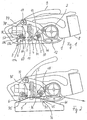
- a strapping tool according to the invention shown, in the housing 1, a clamping device with a Clamping drive 2, designed as a welding device Closure device 3, a cutting device 4, and three backstops are arranged, of which in Fig. 1st however, only the two backstops 5, 6 can be seen are.
- the housing 1 has a below these components Base plate 7, which is divided into two arms 11, 12.
- the two arms 11, 12 are spaced apart arranged and open an opening between them.
- a Contact surface 11a of the arm 11 for the arrangement of the Strapping tool on packaged goods can not in others illustrated embodiments of the invention, concave be curved so that the device can also be used on round packaged goods can be safely arranged.
- a hand lever 9 triggered by one on the housing 1 stored axis of rotation 10 from a first end position in a second end position is pivotable.
- a first swivel arm 13 on the axis of rotation 10 rotatably arranged.
- the swivel arm 13 is also on one plate-shaped and essentially triangular Control board 14 attached to which also a second Swivel arm 15 and a tab 16 are articulated.
- the tab 16 is provided with a backdrop 17.
- a first double lever 19 is located, which has two lever arms 20, 21. At the ends at least one of the two lever arms 20, 21 is free rotatable roller arranged.
- the second double lever 25 is on a pivot axis 27 of the tensioning drive arranged and has a second Lever arm, which is provided with a pawl 28.
- the tensioning drive also mounted on the swivel axis 27 2 can by operating the hand lever around the pivot axis 27 are pivoted.
- the tension drive 2 has a a wave of a not shown DC motor arranged tensioning wheel 30.
- Coaxial to Tensioning wheel 30 is a ring gear 31 on the same shaft Planetary gear arranged, the circumference with two itself diametrically opposite recesses 35, 36 provided is.
- the depressions 35, 36 are for engagement of the pawl 28 the third backstop 26 is provided. Through a such engagement can the ring gear 31 against rotational movements in Locked counterclockwise.
- all information about a sense of rotation of course always on the respective presentation refer in the figures.
- the figures do not show that not only that Achieving a reduction of the planetary gear provided to the tensioning wheel 30, but also the DC motor to the two previously mentioned components is arranged coaxially. This arrangement also helps with the strapping tool to achieve the highest possible efficiency.
- the planetary gearbox has three - instead of the usual two for hand strapping tools - Reduction levels.
- the second arm 12 of the base plate 7 (Fig. 1) is below the tensioning wheel 30 arranged.
- a rocker 37 which is around a Rocker axis 38 is pivotable (Fig. 5 - 7).
- the storage of the Rocker 37 is made so that it is about your Rocker axis 38 can rotate freely, which makes them according to the size and direction of the pressure of the band or the tensioning wheel 30 aligns itself.
- a freely rotatable counter roller 39, 40 is attached, those without a belt of an envelope drive, such as a V-belt, act directly on the strapping.
- the tensioning wheel 30 is pivoted about the Swivel axis 27 in contact against the two rollers 39, 40 brought.
- the distance between the two counter rollers should therefore be dimensioned such that a sufficiently large Set the wrap angle ( ⁇ ) of the belt on the tensioning wheel (Fig. 6).
- This means that the Wrap angle should have a size through which a Slip of the tape against the tensioning wheel at least in is essentially avoidable.
- this value may vary depending on, for example, the Pressure force of the tensioning wheel against the seesaw Surface condition and the material of the tensioning wheel, the band type, etc. vary.
- a pivotable pawl 44 is also mounted on the same shaft of rocker 37 as that in Tensioning direction (arrow 43) rear counter roller 40 of rocker 37.
- a pivotable pawl 44 is also mounted on the same shaft of rocker 37 as that in Tensioning direction (arrow 43) rear counter roller 40 of rocker 37.
- a pivotable pawl 44 is also mounted on the same shaft of rocker 37 as that in Tensioning direction (arrow 43) rear counter roller 40 of rocker 37.
- a pivotable pawl 44 is also mounted on the same shaft of rocker 37 as that in Tensioning direction (arrow 43) rear counter roller 40 of rocker 37.
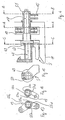
- the front backstop 5 shown in Fig. 1 is - 4 - with a sleeve-shaped section 47 on an eccentric axis 48 stored, which in turn is arranged on the axis of rotation 18. This storage is carried out so that the front or first backstop 5 relative to the axis of rotation 18 relative is rotatable.
- the backstop 5 is not one shown, acting approximately in the direction of tape tension, spring provided by the backstop 5 on the first arm 11 of the base plate 7 is pressed.
- the transfer of a Rotary movement takes place by placing one on the eccentric axis arranged driving cam 49, which on a sleeve-shaped section provided driver cams 50 presses (Fig. 4 and 15). Coupling the backstop 5 with the eccentric axis 48 thus takes place through a positive engagement of the two driver cams 49, 50.
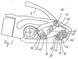
- the switching disk 51 is with a spring 42 shown in Fig. 3 for Clockwise rotary movements are subjected to force.
- the Switching disk 51 has claws 54a, 54c on the front side Coupling on (see FIG. 14) through which the switching disc 51st is rotatably connected to the swivel arm 15. For this are in each case the two claws 54a, 54c on one end face of the Switch disc 51 arranged diametrically opposite. Two other claws 54b, 54d are on the swivel arm 15 and are also diametrically opposite.
- the double lever 19 mounted rotatably on the eccentric axis 48 and with the second swivel arm 15 by a further claw coupling non-rotatably connected (Fig. 4 and 13).
- This clutch too has four claws 55a-55d which interlock. Contrary to the claw coupling discussed earlier here the claws 55c, 55d of the double lever 19 to the claws 55a, 55b of the swivel arm 15 no play in the circumferential direction on, which makes it non-rotatable in all rotational positions Connection between the double lever 19 and the swivel arm 15 given is.
- the rotational positions of the double lever 19 on the Eccentric axis 48 is thus on the swivel arm 15 and the Control board 14 determined by the hand lever 9.
- the respective Position of the hand lever 9 also has a corresponding one Position of the eccentric axis 48 relative to the axis of rotation 18 Sequence (Fig. 3 and 4).
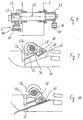
- the second backstop 6 is through a second axis of rotation 56 actuated, which is mounted on the housing 1 (Fig. 1 and 8).
- a sleeve-shaped locking lever 58 is the second Backstop 6 on a second eccentric axis 57 arranged, which is eccentric with respect to the axis of rotation 56 is aligned.
- the eccentric axis 57 is with the axis of rotation 56 connected in one piece.
- the locking lever 58 and the Eccentric axis 57 are by creating a nose 58a of the Locking lever 58 on a driver 57a of the eccentric axis 57 in certain rotational positions of the axis of rotation 56 rotatably connectable to each other (Fig. 8 - 10).
- 9 is one non-rotatable connection and in Fig. 10 a constellation shown, in which no slewing ring between the Locking lever 58 and the eccentric axis 57.
- a sleeve is designed as a ratchet lever 59.
- One of two arms 60, 61 of the ratchet lever 59 is in the backdrop 17 of the Control board 14 pivotally hinged tab 16 out (Fig. 3).
- On the other arm 61 of the ratchet lever 59 can a rotatable pawl 64 act and in a locked position the ratchet lever 59 against rotational movements in Lock counterclockwise.
- the arm 61 of the Pawl lever 59 attached a tension spring 62 with which the arm 61 is pressed against a pawl 64.
- Jack 64 in turn can by a nose 65 of the control board 14 their locked position can be rotated, causing the latch lever 59 is movable in both directions of rotation.
- a movement triggered by the hand lever 9 Control board 14 leads, among other things. to a rotational movement of the second axis of rotation 56, whereby the locking lever 58 one for Axis of rotation 56 performs eccentric pivoting movement (FIG. 1, 3 and 8).
- a Locking lever 58 articulated locking plate 66 on a Bevel 67 of the first arm 11 of the base plate 7 is pressed on or be lifted off again (Fig. 9 and 10). So that a toothed pressure surface 68 of the locking plate 66 at the first contact with the slope 67 at least in is aligned approximately parallel to this Locking plate 66 loaded with a tension spring 69.
- the rotary movement caused by the tension spring 69 by limited a nose 70 of the locking plate that with the Locking lever 58 comes into contact when the locking plate 66 of the slopes are lifted.
- the Locking lever comes from the position shown in Fig. 9 in the position shown in Fig. 10, in which the Locking plate 66 presses the tape against the base plate.
- the Arrangement of the driver 57a of the nose 58a and the Direction of action of the tension spring 69 (FIGS. 9 and 10) on the one Side and the direction of action of the tension spring 62 and the length the backdrop 17 (Fig.
- the closure device has a transmission element in the form of a bracket 80 in which a counter cam 81 provided with a roller for cam 77 is stored.
- the bracket 80 is also on one Axis of rotation 82 on the arm 11 of the base plate of the strapping tool articulated.
- the bracket 80 thus serves, among other things. to Transmission of a certain part of the swiveling movement of the Lever 9, on the principle of friction welding based locking device.
- a supports 83 which extend approximately horizontally, which is via a compression spring 84 on the arm 11 of the base plate supported.
- An electric motor 85 is on the carrier 83 arranged with which an oscillating movement of a Welding shoe 86 is generated.
- the carrier 83 is with a Bearing 90 provided at which an angled one-piece lever 91 is articulated.
- a drive shaft 92 of the motor 85 between the axis of rotation 82 and the bearing 90 for the lever 91 all three Components roughly on an (imaginary) Connecting straight lines 87 can be arranged as shown in Fig. 16 is shown.
- Via an elastic spring element 93 preferably a plate spring assembly, supports the Carrier 83 against the bracket 80.
- One end 91a of the lever is designed as a fork, the both arms form an elongated hole 93 which is open on one side.
- the eccentric element is on the shaft 92 of the motor eccentrically supported and with an essentially provided circular peripheral surface on which a Inner ring of the rolling bearing is located.
- the roller bearing 94a is located with a peripheral surface 94b of its outer ring on both Arms of the fork.
- FIG. 17 is finally a toothed counter plate 96 shown against the one during the welding process Position of the tape is pressed.
- the counter plate 96 in the arm 11 of the Base plate by an essentially transverse to the longitudinal direction of the tape in the closing device axis 97 pivotally arranged.
- the axis 97 also runs orthogonal to the pivot axis 86a of the welding shoe 86, the again essentially parallel to the longitudinal direction of the Band 45 is aligned.
- the compression spring 84 serves to reset the carrier 83 and counteracts the spring element 93.
- the component thus becomes the drive for the welding shoe 86 the eccentric movement, which is roughly vertical to the Straight line 87 runs.
- the straight line 87 approximately parallel component of the eccentric movement is balanced by the slot of the fork and leads to no movement of the lever 91.
- the device To a with the strapping device according to the invention Belt loop 46 to place a packaged product, close and To disconnect from the tape supply, the device should first be used its base plate 7 can be arranged on the packaged goods.
- the hand lever 9 should be in one Starting position, which of those shown in Fig. 2 Intermediate position between the two end positions corresponds. In this position of the hand lever 9 is a locking plate 71st the first backstop 5 and a counter knife 74 of the Cutting device on the base plate. The difference 2 is in this phase no strap has been inserted into the strapping tool yet.
- the second and the third backstop 6, 29 are closed solved at this time.
- the lock plate 66 of the second backstops 6 is in one position arranged at the greatest distance from the base plate 7 has.
- the pawl 44 (Fig. 5) is the third backstop does not engage the ring gear 31 and the tension drive 2 is lifted off the rocker 37.
- the Welding device is also from its arm 11 Base plate 7 raised.
- the hand lever 9 is pivoted into an end position, in which it bears against the housing 1 above the swivel drive (Fig. 1).
- This first movement of the hand lever 9 is over the first swivel arm 13 on the control board 14 transfer.
- the control board 14 in turn rotates the second Swivel arm 15. Since in this position the claws 54b, 54d of the second pivot arm 15 with the claws 54a, 54c Switch disc 51 are engaged, the rotational movement is on the switching disc 51 and thereby also on the axis of rotation 18 transfer.
- This movement of the axis of rotation 18 in turn leads to ensure that the clutch (drive cams 49, 50) between the axis of rotation 18 and the first backstop 5 in engagement comes.
- the strap can then be inserted into the strapping tool and be placed around the packaged goods.
- Band loop 46 through an opening 76 in the base plate 7 out and placed in the device so that it is under the backstop 6 both the tape end 75 and a another portion of the strap loop 46 is located while under the backstop 5 only the extended one Band end 75 is arranged.
- closure device actuates the cam 77 the counter cam 81 This lowers the counter knife 74 on the tape, while the condition of Closure device remains unchanged.
- band 45 also in the gap between the Tensioning wheel 30 and the counter rollers 39, 40 of the rocker 37 are introduced (see. Fig. 5, 6, 7).
- a (not shown) Tension button of the hand lever 9 actuated, whereby the DC motor of the tension drive 2 is started.
- the drive movement of the motor is controlled by the Transfer the planetary gear to the tensioning wheel 30, which - by rotating it counterclockwise - the tape in the direction (arrow 43 in FIGS. 2 and 5) to one not withdrawing the illustrated supply roll.
- the movement of the Tensioning wheel is stopped when the intended tension on the tape is applied, for which the current actual Motor current is compared with a nominal value of the current.
- the engine is switched off, where the setpoint of the motor current of a certain desired nominal belt tension of a certain belt type equivalent.
- the backstop 5 clamps the Band end.
- the pawl 28 is in the position shown in Fig. 6, in which it has a rotational movement the rotating against the direction of rotation of the tensioning wheel 30 Ring gear 31 only in one direction of rotation. Since that Ring gear 31 is rotationally coupled to the tensioning wheel thus the tensioning wheel against rotation against Clamping direction blocked. The tension wheel can thus at most by 180 ° in the opposite direction to the clamping direction Turn direction. Then at the latest the latch will snap into one of the two recesses 35, 36 of the ring gear 31.
- the hand lever 9 - starting from the intermediate position (see FIGS. 2 and 3) - transferred to its second end position, shown in Fig. 11 is.
- the movement of the control board 14 triggered thereby leads to the nose 65 of the control board 14 the pawl 64 rotates out of its locked position, causing the latch lever 59 becomes free for counterclockwise rotation.
- the tab 16 can now the pawl lever 59th Turn counterclockwise (Fig. 12).
- Unlike the movement of the hand lever 9 from the intermediate position in the ratchet lever is now in the first end position and back one of the ends of the backdrop 17 and is through the tab 16 coupled to the movement of the control board 14.
- the movement of the ratchet lever 59 leads to a lowering of the locking plate 66 in the direction of the Base plate 7, which also makes the backstop 6 the belt stuck. Due to the previously described articulation of the Locking plate 66 ensures that the locking plate the first time you touch the tape in the substantially parallel to the slope 67 of the base plate 7 is aligned and the tape is clamped very quickly can be.
Abstract
Description
Die Erfindung betrifft ein Umreifungsgerät zur Umreifung von Packgut mit einem Band, wobei das Umreifungsgerät eine mit einem Spannantrieb wirkverbundene Spanneinrichtung zum Spannen des Bandes, eine Verschlusseinrichtung zum Verschliessen von zwei Bandenden eines Bandes, und mehrere Rücklaufsperren zur Fixierung des Bandes im Umreifungsgerät, aufweist (siehe zum Beispiel US 1 136 845 A).The invention relates to a strapping tool for strapping Packaged goods with a strap, the strapping tool with a a tensioning drive operatively connected tensioning device for Tensioning the tape, a closure device for Closing two ends of a band, and several Backstops to fix the strap in the strapping tool, (see for example US 1 136 845 A).
Die Erfindung bezieht sich in erster Linie auf tragbare, mobile, d.h. nicht stationäre und fest installierte, Umreifungsgeräte, die vorzugsweise elektrisch angetrieben und mit einer netzunabhängigen Stromversorgung, wie beispielsweise einem Akkumulator, versehen sind.The invention relates primarily to portable, mobile, i.e. non-stationary and permanently installed, Strapping tools, preferably electrically powered and with an off-grid power supply like for example, an accumulator.
Derartige Geräte werden zur Umreifung von Packgut mit einem Kunststoffband verwendet. Hierzu wird das Umreifungsgerät auf dem Packgut angeordnet und eine Bandschlaufe um das Packgut gegeben und in das Umreifungsgerät eingelegt. Das Bandende sowie das noch abzutrennende zweite Ende der Bandschlaufe sind hierbei im Umreifungsgerät angeordnet. Anschliessend wird mittels der Spanneinrichtung des Umreifungsgerätes auf das Band eine Bandspannung aufgebracht. Durch einen nachfolgenden Schweissvorgang zweier übereinanderliegender Bandlagen und ein Abtrennen der Bandschlaufe von der Bandvorratsrolle wird der Umreifungsvorgang beendet.Such devices are used for strapping packaged goods with a Plastic strap used. For this, the strapping tool arranged on the packaged goods and a ribbon loop around the Packaged goods and placed in the strapping tool. The End of the band and the second end of the The strap loop is arranged in the strapping tool. Then the Strapping device on the strap a strap tension applied. Through a subsequent welding process two superimposed band layers and a separation of the The tape loop from the tape supply roll becomes the Strapping process finished.
Bei solchen mobilen Umreifungsgeräten ist man stets bestrebt, Gewicht zu sparen, um die Handhabbarkeit und Transportierbarkeit der Geräte zu verbessern. Soweit die vom Motor angetriebenen Bauteile des Gerätes betroffen sind, bedeutet ein geringes Gewicht dieser Bauteile in der Regel auch eine Reduzierung der pro Umreifung benötigten Energiemenge, wodurch sich die mit einer Akkumulatorladung erzielbare Anzahl an Umreifungen vergrössern lässt.One is always with such mobile strapping tools strives to save weight, ease of use and To improve the portability of the devices. As far as from Motor-driven components of the device are affected usually means a low weight of these components also a reduction in the required per strapping Amount of energy, resulting in a battery charge achievable number of straps can be increased.
Der Erfindung liegt deshalb die Aufgabe zugrunde, ein Umreifungsgerät zu schaffen, das bei hoher Funktionssicherheit möglichst leicht ist.The invention is therefore based on the object Strapping tool to create that at high Functional safety is as easy as possible.
Diese Aufgabe wird bei einem eingangs erwähnten Umreifungsgerät erfindungsgemäss dadurch gelöst, dass Steuerfunktionen für Rücklaufsperren über lediglich eine zentrale Steuerplatine von einem Handhebel auf die Rücklaufsperren übertragen werden. Die Steuerplatine überträgt vorzugsweise für sämtliche vorhandenen Rücklaufsperren deren Steuerungsfunktionen. Hierdurch lässt sich die Anzahl an Einzelteilen verringern, wodurch sich das Gewicht des als mobiler Handapparat vorgesehenen Umreifungsgerät reduzieren lässt. Da sämtliche Steuerfunktionen von einem zentralen Handhebel ausgelöst werden, wird hierdurch auch die Bedienung des Umreifungsgerätes erleichert.This task is mentioned in one Strapping device according to the invention solved in that Control functions for backstops using only one central control board from a hand lever to the Backstops are transmitted. The control board transmits preferably for all existing ones Backstops their control functions. This leaves the number of individual parts decrease, which makes it Weight of the intended as a mobile handset Strapping tool can be reduced. Because everyone Control functions triggered by a central hand lever be, this also the operation of the Strapping tool relieved.
Da eine erfindungsgemässe Steuerplatine vorzugsweise schwenkbar angelenkt sein kann und Schwenk- bzw. Drehbewegungen im Vergleich zu translatorischen Bewegungen mit geringerem konstruktiven Aufwand zu beherrschen sind, kann hierdurch eine vergleichsweise funktionssichere und trotzdem bezüglich des Gewichtes leichte Steuerungseinrichtung geschaffen werden. In einer besonders bevorzugten Ausführungsform ist die Steuerplatine an drei Stellen schwenkbar angelenkt, wobei an sämtlichen Anlenkstellen der Steuerplatine Steuerfunktionen für das Umreifungsgerät übertragen werden. Eine weitere Gewichtsreduzierung kann erzielt werden, wenn die Steuerplatine nur mittels der Anlenkpunkte geführt ist und somit separate Führungsmittel vermieden werden können. Since a control board according to the invention is preferred can be pivoted and pivoting or Rotational movements compared to translatory movements can be mastered with less design effort, can be a comparatively reliable and nevertheless light in weight Control device can be created. In one particularly preferred embodiment, the control board is three Places pivoted, on all Articulation points of the control board control functions for the Strapping tool can be transferred. Another Weight reduction can be achieved if the Control board is guided only by means of the articulation points and separate guide means can thus be avoided.
Eine konstruktiv besonders einfache und platzsparende Ausbildung eines erfindungsgemässen Umreifungsgerätes kann vorsehen, dass die Steuerplatine über einen Schwenkhebel mit dem Handhebel verbunden ist. Mit der Steuerplatine können Übertragungsmittel, beispielsweise Drehachsen, verbunden sein, durch welche die Rücklaufsperren von einer Sperrstellung in eine Einführposition bzw. vice versa überführt werden.A particularly simple and space-saving design Formation of a strapping device according to the invention provide that the control board with a swivel lever the hand lever is connected. With the control board you can Transmission means, for example axes of rotation connected through which the backstops of one Locked position in an insertion position or vice versa be transferred.
In einer weiteren bevorzugten Ausführungsform weist ein Umreifungsgerät zumindest zwei Rücklaufsperren auf, mit denen das Band fixierbar ist. Hierbei sollte die Verschlusseinrichtung zwischen den beiden Rücklaufsperren angeordnet sein. Diese Anordnung hat sich insbesondere für solche Anwendungsfälle bewährt, bei denen das Band beim Spannvorgang von der Spannvorrichtung aus der Verschlusseinrichtung "herausgezogen" und nicht "hineingeschoben" wird. Das heisst, es handelt sich um einen konstruktiven Aufbau eines Umreifungsgerätes, bei dem die Spanneinrichtung in Spannrichtung hinter der Verschlusseinrichtung angeordnet ist. Es ist jedoch besonders bevorzugt, wenn eine dritte Rücklaufsperre vorhanden ist, mit der das Spannrad fixierbar ist. Hierbei sollte das Spannrad zumindest gegen Drehbewegungen in Spannrichtung arretierbar sein. Mit dieser Anordnung ist es möglich, das beim Spannvorgang durch die Verschlusseinrichtung hindurchgezogene Band bei bereits aufgebrachter Bandspannung für den Verschluss- und Schneidevorgang zu fixieren und trotzdem jenen Bandabschnitt, der nachfolgend reibverschweisst und geschnitten wird, von der Bandspannung im wesentlichen wieder zu entlasten. Dies hat den Vorteil, dass sich die vorzugsweise im wesentlichen quer zur Längserstreckung des Bandes erfolgende Bewegung des Schweissschuhs besser in Wärme des Bandes umsetzen lässt, und dass beim Schneiden des Kunststoffbandes saubere Schneidkanten entstehen. Unter Spannung stehende Kunststoffbänder tendieren beim Schneiden dazu zu spleissen, wodurch die Funktionssicherheit des Gerätes beeinträchtigt werden kann.In a further preferred embodiment, a Strapping tool with at least two backstops to whom the tape can be fixed. Here, the Locking device between the two backstops be arranged. This arrangement has been particularly useful for proven use cases in which the tape at Clamping process from the clamping device from the Locking device "pulled out" and not is "pushed in". That means it is one constructive construction of a strapping tool, in which the Clamping device in the clamping direction behind the Closure device is arranged. However, it is particularly preferred if a third backstop is available with which the tensioning wheel can be fixed. in this connection the tensioning wheel should at least prevent rotation Clamping direction can be locked. With this arrangement it is possible that during the clamping process by the Closure device pulled tape through already applied tape tension for the closure and Fix the cutting process and still that Band section, which is subsequently friction-welded and is cut from the tape tension essentially to relieve again. This has the advantage that the preferably substantially transverse to the longitudinal extent of the Banding movement of the welding shoe better in Can convert heat of the tape, and that when cutting the Plastic tape clean cutting edges arise. Under Tensioned plastic tapes tend to cut to splicing, thereby the functional reliability of the Device can be affected.
Um eine funktionssichere Rücklaufsperre auszubilden, kann bei einem eingangs erwähnten Umreifungsgerät erfindungsgemäss auch vorgesehen sein, dass ein Sperrhebel der zumindest einen Rücklaufsperre auf einer Exzenterachse gelagert ist, die mit einer Drehachse verbunden ist und die gegenüber der Drehachse exzentrisch angeordnet ist. Hierbei sollte der Sperrhebel über eine Kupplung mit der Drehachse rotatorisch verbindbar und auf der Exzenterachse frei drehbar angeordnet sein. Mit dieser Anordnung kann eine Rücklaufsperre sehr schnell von einer Einführposition für das Band in eine Klemmposition überführt werden. Durch die hiermit erzielbare hohe Beschleunigung der Rücklaufsperre kann das Band schnell und sicher geklemmt werden, was zur Funktionssicherheit des Gerätes beiträgt.To form a reliable backstop, can in a strapping device mentioned at the beginning According to the invention it can also be provided that a locking lever the at least one backstop on an eccentric axis is mounted, which is connected to an axis of rotation and the is arranged eccentrically with respect to the axis of rotation. in this connection the locking lever should have a coupling with the axis of rotation rotatory connectable and free on the eccentric axis be rotatably arranged. With this arrangement, a Backstop very quickly from an insertion position for the tape is transferred to a clamping position. Through the hereby achievable high acceleration of the backstop the tape can be clamped quickly and securely, resulting in Functional reliability of the device contributes.
Weitere bevorzugte Ausgestaltungen der Erfindung ergeben sich aus den abhängigen Ansprüchen.Further preferred configurations of the invention result itself from the dependent claims.
Die Erfindung wird anhand den in den Figuren schematisch dargestellten Ausführungsbeispielen näher erläutert; es zeigen:
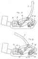
- Fig. 1
- ein erfindungsgemässes Umreifungsgerät in einer ersten Seitenansicht, wobei sich ein Handhebel in einer ersten Endlage befindet;
- Fig. 2
- das Umreifungsgerät von Fig. 1 mit einer anderen Stellung eines Handhebels;
- Fig. 3
- das Umreifungsgerät von Fig. 2 in einer Ansicht von hinten;
- Fig. 4
- eine Schnittdarstellung einer Drehachse des Umreifungsgerätes;
- Fig. 5
- ein Spannantrieb des Umreifungsgerätes;
- Fig. 6
- der Spannantrieb von Fig. 5 während einer Spannphase;
- Fig. 7
- der Spannantrieb von Fig. 5 während eines Schweissvorganges;
- Fig. 8
- eine Schnittdarstellung einer weiteren Drehachse des Umreifungsgerätes;
- Fig. 9
- eine Rücklaufsperre des Umreifungsgerätes in einer ersten Endlage;
- Fig. 10
- die Rücklaufsperre von Fig. 9 in einer zweiten Endlage;
- Fig. 11
- eine Darstellung des Umreifungsgerätes gemäss Fig. 3, wobei sich der Handhebel in einer zweiten Endlage befindet;
- Fig. 12
- eine Darstellung des Umreifungsgerätes gemäss Fig. 3, wobei sich der Handhebel in einer Zwischenstellung befindet;
- Fig. 13
- eine Schnittdarstellung entlang der Linie A - A in Fig. 4;
- Fig. 14
- eine Schnittdarstellung entlang der Linie B - B in Fig. 4;
- Fig. 15
- eine Schnittdarstellung entlang der Linie C - C in Fig. 4;
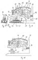
- Fig. 16
- ein Teil einer möglichen - sich in einer Schweissposition befindenden - erfindungsgemässen Schweisseinrichtung in einer teilweise geschnittenen Darstellung. Die Schweisseinrichtung von Fig. 16 unterscheidet sich von der in Fig. 1 stark schematisiert dargestellten Schweisseinrichtung;
- Fig. 17
- eine Schnittdarstellung gemäss der Linie D-D von Fig. 16;
- Fig. 18
- die Schweisseinrichtung von Fig. 16 in einer Einführposition.
- Fig. 1
- a strapping device according to the invention in a first side view, wherein a hand lever is in a first end position;
- Fig. 2
- the strapping device of Figure 1 with a different position of a hand lever.
- Fig. 3
- the strapping device of Figure 2 in a view from behind.
- Fig. 4
- a sectional view of an axis of rotation of the strapping tool;
- Fig. 5
- a tension drive of the strapping tool;
- Fig. 6
- 5 during a clamping phase;
- Fig. 7
- the tension drive of Figure 5 during a welding process.
- Fig. 8
- a sectional view of another axis of rotation of the strapping tool;
- Fig. 9
- a backstop of the strapping tool in a first end position;
- Fig. 10
- the backstop of Figure 9 in a second end position.
- Fig. 11
- an illustration of the strapping device according to FIG 3, wherein the hand lever is in a second end position.
- Fig. 12
- an illustration of the strapping device according to FIG 3, wherein the hand lever is in an intermediate position.
- Fig. 13
- a sectional view taken along line A - A in Fig. 4;
- Fig. 14
- a sectional view taken along line BB in Fig. 4;
- Fig. 15
- a sectional view taken along the line C - C in Fig. 4;
- Fig. 16
- a part of a possible welding device according to the invention, which is in a welding position, in a partially sectioned illustration. 16 differs from the welding device shown in a highly schematic manner in FIG. 1;
- Fig. 17
- a sectional view along the line DD of Fig. 16;
- Fig. 18
- 16 in an insertion position.
In Fig. 1 ist ein erfindungsgemässes Umreifungsgerät
gezeigt, in dessen Gehäuse 1 eine Spanneinrichtung mit einem
Spannantrieb 2, eine als Schweisseinrichtung ausgebildete
Verschlusseinrichtung 3, eine Abschneideeinrichtung 4, sowie
drei Rücklaufsperren angeordnet sind, von denen in Fig. 1
allerdings nur die beiden Rücklaufsperren 5, 6 zu erkennen
sind. Das Gehäuse 1 weist unterhalb dieser Bauelemente eine
Grundplatte 7 auf, die in zwei Arme 11, 12 unterteilt ist.
Die beiden Arme 11, 12 sind mit Abstand zueinander
angeordnet und geben zwischen sich eine Öffnung frei. Eine
Auflagefläche 11a des Armes 11 zur Anordnung des
Umreifungsgerätes auf Packgut kann, in anderen nicht
dargestellten Ausführungsbeispielen der Erfindung, konkav
gekrümmt sein, damit das Gerät auch auf rundem Packgut
sicher angeordnet werden kann.1 is a strapping tool according to the invention
shown, in the
Sämtliche Funktionen des mit einer Batterie bzw. einem
Akkumulator 8 versehenen Umreifungsgerätes werden durch
einen Handhebel 9 ausgelöst, der um eine am Gehäuse 1
gelagerten Drehachse 10 von einer ersten Endlage in eine
zweite Endlage schwenkbar ist. Wie insbesondere in Fig. 3 zu
erkennen ist, ist ein erster Schwenkarm 13 auf der Drehachse
10 drehfest angeordnet. Der Schwenkarm 13 ist zudem an einer
plattenförmigen und im wesentlichen dreieckigen
Steuerplatine 14 befestigt, an der ausserdem ein zweiter
Schwenkarm 15 und eine Lasche 16 angelenkt sind. Die Lasche
16 ist mit einer Kulisse 17 versehen.All functions of the with a battery or a
In den Fig. 4 und 5 ist gezeigt, dass auf einer Drehachse 18
des zweiten Schwenkarmes 15 sich ein erster Doppelhebel 19
befindet, der zwei Hebelarme 20, 21 aufweist. An den Enden
der beiden Hebelarme 20, 21 ist jeweils zumindest eine frei
drehbare Rolle angeordnet. Im Schwenkbereich des ersten
Doppelhebels befindet sich ein Hebelarm 24 eines zweiten
Doppelhebels 25, der zu einer dritten Rücklaufsperre 26
gehört. Der zweite Doppelhebel 25 ist auf einer Schwenkachse
27 des Spannantriebes angeordnet und weist einen zweiten
Hebelarm auf, der mit einer Klinke 28 versehen ist.4 and 5 show that on an axis of
Der ebenfalls auf der Schwenkachse 27 gelagerte Spannantrieb
2 kann durch Betätigung des Handhebels um die Schwenkachse
27 verschwenkt werden. Der Spannantrieb 2 weist ein auf
einer Welle eines nicht näher dargestellten
Gleichstrommotors angeordnetes Spannrad 30 auf. Koaxial zum
Spannrad 30 ist auf der gleichen Welle ein Hohlrad 31 eines
Planetengetriebes angeordnet, dessen Umfang mit zwei sich
diametral gegenüberliegenden Vertiefungen 35, 36 versehen
ist. Die Vertiefungen 35, 36 sind zum Eingriff der Klinke 28
der dritten Rücklaufsperre 26 vorgesehen. Durch einen
solchen Eingriff kann das Hohlrad 31 gegen Drehbewegungen im
Gegenuhrzeigersinn gesperrt werden. Hierbei ist zu
berücksichtigen, dass sämtliche Angaben über einen Drehsinn
sich selbstverständlich stets auf die jeweilige Darstellung
in den Figuren beziehen.The tensioning drive also mounted on the
In den Figuren ist nicht dargestellt, dass nicht nur das zur
Erzielung einer Untersetzung vorgesehenes Planetengetriebe
zum Spannrad 30, sondern auch der Gleichstrommotor zu den
beiden zuvor genannten Bauteilen koaxial angeordnet ist.
Auch diese Anordnung trägt dazu bei, mit dem Umreifungsgerät
einen möglichst hohen Wirkungsgrad zu erzielen. Um den
Wirkungsgrad zu erhöhen weist das Planetengetriebe drei -
anstelle der sonst bei Handumreifunggeräten üblichen zwei -
Untersetzungsstufen auf.The figures do not show that not only that
Achieving a reduction of the planetary gear provided
to the
Der zweite Arm 12 der Grundplatte 7 (Fig. 1) ist unterhalb
des Spannrades 30 angeordnet. In einer Vertiefung des
zweiten Armes 12 befindet sich eine Wippe 37, die um eine
Wippenachse 38 schwenkbar ist (Fig 5 - 7). Die Lagerung der
Wippe 37 ist hierbei so vorgenommen, dass sie sich um ihre
Wippenachse 38 frei drehen kann, wodurch sie sich
entsprechend der Grösse und der Wirkrichtung des Andrucks
des Bandes bzw. des Spannrades 30 von selbst ausrichtet. An
den Enden zweier im wesentlichen gleich langer Wippenarme
ist jeweils eine frei drehbare Gegenrolle 39, 40 angebracht,
die ohne einen Riemen eines Hülltriebes, wie beispielsweise
einen Keilriemen, direkt auf das Umreifungsband einwirken.
Von den im wesentlichen parallel zur Wippenachse
ausgerichteten beiden Achsen der Gegenrollen 39, 40 befindet
sich - in bezug auf die Spannrichtung (Pfeil 43) - eine
Achse bzw. Gegenrolle vor und die andere Gegenrolle hinter
der Wippenachse 38. Die Abstände der Achsen der Gegenrollen
39, 40 zur Wippenachse 38 sind somit im wesentlichen gleich
gross. Des weiteren ist in den Darstellungen der Fig. 5 - 7
zu erkennen, dass eine imaginäre Verbindungslinie 41 von
einer Drehachse des Spannrades mit der Wippenachse 38 im
wesentlichen orthogonal zum Arm 12 der Grundplatte
ausgerichtet ist.The
Das Spannrad 30 ist durch eine Schwenkbewegung um die
Schwenkachse 27 in Anlage gegen die beiden Rollen 39, 40
bringbar. Der Abstand der beiden Gegenrollen sollte deshalb
so bemessen sein, dass sich ein ausreichend grosser
Umschlingungswinkel (α) des Bandes am Spannrad einstellt
(Fig. 6). Hierunter ist zu verstehen, dass der
Umschlingungswinkel eine Grösse haben sollte, durch den ein
Schlupf des Bandes gegenüber dem Spannrad zumindest im
wesentlichen vermeidbar ist. Im dargestellten
Ausführungsbeispiel beträgt der Abstand der beiden -
gegenüber dem Spannrad weitaus kleineren - Gegenrollen 39,
40 in etwa 70% des Radius des Spannrades. Selbstverständlich
kann dieser Wert in Abhängigkeit von beispielsweise der
Andruckkraft des Spannrades gegen die Wippe, der
Oberflächenbeschaffenheit und dem Werkstoff des Spannrades,
der Bandsorte, etc. variieren. Schliesslich kann aufgrund
der geometrischen Verhältnisse auch vorgesehen sein, dass
eine resultierende Andruckkraft des Spannrades gegen die
Wippe 37 die Wippenachse nicht schneidet. Hierdurch entsteht
bei Andruck des Spannrades gegen die Wippe stets ein
Drehmoment um die Wippenachse 38, wodurch sich eine
besonders gute Ausrichtung der Wippe gegenüber dem Spannrad
erzielen lässt.The
Auf der gleichen Welle der Wippe 37, wie die in
Spannrichtung (Pfeil 43) hintere Gegenrolle 40 der Wippe 37,
ist zudem eine schwenkbare Klinke 44 gelagert. In einer in
Fig. 5 gezeigten Grundstellung ist die Klinke 44 im
wesentlichen vertikal ausgerichtet. In dieser Grundstellung
stützt sich das Spannrad 30 nur auf der Klinke 44 ab.
Hierdurch wird zwischen dem Spannrad 30 und den Gegenrollen
39, 40 ein Spalt ausgebildet, in den das - in Fig. 6
gezeigte - zu spannende Band 45 einführbar ist. Wie Fig. 6
entnommen werden kann, nimmt das Spannrad 30 bei
Drehbewegungen im Gegenuhrzeigersinn die Klinke 44 mit.
Diese dreht sich dadurch im Uhrzeigersinn in eine andere
Endlage, in welcher das Spannrad 30 auf die Wippe 37
absenkbar ist. Hierbei handelt es sich um die Spannstellung
des Umreifungsgerätes, in der auf eine Bandschlaufe 46 eine
Spannkraft aufgebracht wird. Da die Wippe 37 schwenkbar
gelagert ist, stellt sich diese hierbei so ein, dass die
beiden Gegenrollen 39, 40 beim Spannen auftretende Kräfte
aufnehmen und in die Grundplatte 7 ableiten kann.On the same shaft of
Die in Fig. 1 gezeigte vordere Rücklaufsperre 5 ist -
entsprechend der Darstellung von Fig. 4 - mit einem
hülsenförmigen Abschnitt 47 auf einer Exzenterachse 48
gelagert, die wiederum auf der Drehachse 18 angeordnet ist.
Diese Lagerung ist so vorgenommen, dass die vordere bzw.
erste Rücklaufsperre 5 gegenüber der Drehachse 18 relativ
drehbar ist. Die Rücklaufsperre 5 ist mit einer nicht
dargestellten, in etwa in Bandzugrichtung wirkenden, Feder
versehen, durch die die Rücklaufsperre 5 auf den ersten Arm
11 der Grundplatte 7 gedrückt wird. Die Übertragung einer
Drehbewegung erfolgt durch Anlage eines an der Exzenterachse
angeordneten Mitnehmernockens 49, der auf einen am
hülsenförmigen Abschnitt vorgesehenen Mitnehmernocken 50
drückt (Fig. 4 u. 15). Die Kopplung der Rücklaufsperre 5 mit
der Exzenterachse 48 erfolgt somit durch einen
formschlüssigen Eingriff der beiden Mitnehmernocken 49, 50.The
An einem Ende der Drehachse 18 des zweiten Schwenkarmes 15
befindet sich ausserdem eine Schaltscheibe 51, die mit der
Drehachse 18 drehfest verbunden ist. Die Schaltscheibe 51
wird mit einer in Fig. 3 dargestellten Feder 42 für
Drehbewegungen im Uhrzeigersinn kraftbeaufschlagt. Die
Schaltscheibe 51 weist stirnseitige Klauen 54a, 54c einer
Kupplung auf (vgl. Fig. 14), durch die die Schaltscheibe 51
mit dem Schwenkarm 15 drehfest verbindbar ist. Hierzu sind
jeweils die zwei Klauen 54a, 54c an einer Stirnseite der
Schaltscheibe 51 diametral gegenüberliegend angeordnet. Zwei
andere Klauen 54b, 54d befinden sich am Schwenkarm 15 und
liegen ebenfalls diametral gegenüber. Da jeweils eine Klaue
des Schwenkarms 15 zwischen zwei Klauen der Schaltscheibe
eingreift, kommt es bei bestimmten Rotationspositionen
zwischen der Schaltscheibe 51 und des Schwenkarmes 15 zu
einer drehfesten Verbindung in Form eines Formschlusses der
Klauen. Dadurch nimmt der Schwenkarm 15 die Schaltscheibe 51
mit, während bei anderen Rotationspositionen
Relativbewegungen zwischen den beiden Elementen möglich
sind.At one end of the axis of
Anders als der zweite Schwenkarm 15 ist der Doppelhebel 19
auf der Exzenterachse 48 drehbar gelagert und mit dem
zweiten Schwenkarm 15 durch eine weitere Klauenkupplung
drehfest verbunden (Fig. 4 und 13). Auch diese Kupplung
weist vier Klauen 55a - 55d auf, die ineinander eingreifen.
Im Gegensatz zu der zuvor erörterten Klauenkupplung weisen
hier die Klauen 55c, 55d des Doppelhebels 19 zu den Klauen
55a, 55b des Schwenkarmes 15 in Umfangsrichtung kein Spiel
auf, wodurch in allen Rotationspositionen eine drehfeste
Verbindung zwischen dem Doppelhebel 19 und dem Schwenkarm 15
gegeben ist. Die Drehpositionen des Doppelhebels 19 auf der
Exzenterachse 48 wird somit über den Schwenkarm 15 und die
Steuerplatine 14 vom Handhebel 9 bestimmt. Die jeweilige
Position des Handhebels 9 hat auch eine entsprechende
Position der Exzenterachse 48 gegenüber der Drehachse 18 zur
Folge (Fig. 3 und 4).Unlike the
Die zweite Rücklaufsperre 6 wird durch eine zweite Drehachse
56 betätigt, die am Gehäuse 1 gelagert ist (Fig. 1 und 8).
Hierzu ist ein hülsenförmiger Sperrhebel 58 der zweiten
Rücklaufsperre 6 auf einer zweiten Exzenterachse 57
angeordnet, die gegenüber der Drehachse 56 exzentrisch
ausgerichtet ist. Die Exzenterachse 57 ist mit der Drehachse
56 einstückig verbunden. Der Sperrhebel 58 und die
Exzenterachse 57 sind durch Anlage einer Nase 58a des
Sperrhebels 58 an einem Mitnehmer 57a der Exzenterachse 57
in bestimmten Rotationspositionen der Drehachse 56 drehfest
miteinander verbindbar (Fig. 8 - 10). In Fig. 9 ist eine
drehfeste Verbindung und in Fig. 10 eine Konstellation
gezeigt, bei der keine Drehverbindung zwischen dem
Sperrhebel 58 und der Exzenterachse 57 besteht.The
Auf der Drehachse 56 befindet sich ausserdem eine Hülse, die
als Klinkenhebel 59 ausgebildet ist. Einer von zwei Armen
60, 61 des Klinkenhebels 59 ist in der Kulisse 17 der an der
Steuerplatine 14 schwenkbar angelenkten Lasche 16 geführt
(Fig. 3). Auf den anderen Arm 61 des Klinkenhebels 59 kann
eine drehbare Klinke 64 einwirken und in einer Sperrstellung
den Klinkenhebel 59 gegen Drehbewegungen in
Gegenuhrzeigerrichtung sperren. Hierzu ist am Arm 61 des
Klinkenhebels 59 eine Zugfeder 62 angebracht, mit welcher
der Arm 61 gegen eine Klinke 64 gedrückt wird. Die Klinke 64
wiederum kann durch eine Nase 65 der Steuerplatine 14 aus
ihrer Sperrstellung gedreht werden, wodurch der Klinkenhebel
59 in beide Drehrichtungen bewegbar ist.On the axis of
Eine durch den Handhebel 9 ausgelöste Bewegung der
Steuerplatine 14 führt u.a. zu einer Drehbewegung der
zweiten Drehachse 56, wodurch der Sperrhebel 58 eine zur
Drehachse 56 exzentrische Schwenkbewegung ausführt (Fig. 1,
3 und 8). Durch diese Schwenkbewegung kann eine am
Sperrhebel 58 gelenkig angelenkte Sperrplatte 66 auf eine
Schräge 67 des ersten Arms 11 der Grundplatte 7 aufgedrückt
bzw. von dieser wieder abgehoben werden (Fig. 9 und 10).
Damit eine verzahnte Andruckfläche 68 der Sperrplatte 66
bereits beim ersten Kontakt mit der Schräge 67 zumindest in
etwa parallel zu dieser ausgerichtet ist, ist die
Sperrplatte 66 mit einer Zugfeder 69 belastet. Ausserdem
wird die von der Zugfeder 69 bewirkte Drehbewegung durch
eine Nase 70 der Sperrplatte begrenzt, die mit dem
Sperrhebel 58 in Kontakt kommt, wenn die Sperrplatte 66 von
der Schrägen abgehoben ist.A movement triggered by the
Damit die Sperrplatte 66 beim Absenken in Richtung zur
Grundplatte eine möglichst grosse Beschleunigung erfährt und
nach Betätigung des Handhebels 9 das Band mit einer hohen
Klemmkraft schnell klemmt, muss zunächst die rotatorische
Fixierung des Sperrhebels 58 gegenüber der Exzenterachse 57
aufgehoben werden. Dies geschieht dadurch, dass die Klinke
64 den Klinkenhebel 59 freigibt (Fig. 3). Die an dem
Klinkenhebel 59 angeordnete vorgespannte Zugfeder 62 bewirkt
dann eine schlagartige Drehbewegung des Klinkenhebels 59 und
damit auch der zweiten Drehachse 56 bzw. der Exzenterachse
57. Hierdurch gibt der Mitnehmer 57a die Nase 58a frei,
weshalb nun die ebenfalls vorgespannte Zugfeder 69 den
Sperrhebel 58 auf der Exzenterachse 57 dreht. Durch die
beiden im Uhrzeigersinn stattfindenden Drehbewegungen, d.h.
einer Drehung der Exzenterachse 57 um die Drehachse 56 und
einer Drehbewegung des Sperrhebels 58 auf - und damit
relativ zur - Exzenterachse 57, erfährt der Sperrhebel eine
grosse Beschleunigung in Richtung auf die Grundplatte 7. Der
Sperrhebel kommt dabei von der in Fig. 9 gezeigten Position
in die in Fig. 10 dargestellte Position, in welcher die
Sperrplatte 66 das Band gegen die Grundplatte drückt. Die
Anordnung des Mitnehmers 57a der Nase 58a sowie die
Wirkrichtung der Zugfeder 69 (Fig. 9 und 10) auf der einen
Seite und die Wirkrichtung der Zugfeder 62 sowie die Länge
der Kulisse 17 (Fig. 3) auf der anderen Seite, sind so
aufeinander abgestimmt, dass der Klinkenhebel 59, kurz bevor
die Sperrplatte das Band berührt (Fig. 9 und 10), an einem
Ende der Kulisse 17 an die Lasche 16 anschlägt. Dadurch wird
die Drehbewegung der Drehachse 56 gestoppt und die Nase des
Sperrhebels liegt nicht mehr am Mitnehmer 57a der
Exzenterachse 57 an. Hierdurch dreht der Sperrhebel 58 nun
nur noch um die Exzenterachse 57 und drückt sich in das Band
ein. Die Zugfeder 69 bewirkt hierbei auch, dass die
Andruckfläche 68 im wesentlichen parallel zur Schräge 67 der
Grundplatte ausgerichtet wird und die Sperrplatte bereits ab
dem ersten Kontakt mit dem Band ihrer gesamten Andruckfläche
auf das Band drückt. So that the locking
In den Fig. 16, 17, 18 ist stark schematisiert ein Teil
einer möglichen erfindungsgemässen Verschlusseinrichtung des
Umreifungsgerätes gezeigt. Die Verschlusseinrichtung weist
ein Übertragungselement in Form eines Bügels 80 auf, in dem
ein mit einer Rolle versehener Gegennocken 81 zum Nocken 77
gelagert ist. Der Bügel 80 ist desweiteren auf einer
Drehachse 82 am Arm 11 der Grundplatte des Umreifungsgerätes
schwenkbar angelenkt. Der Bügel 80 dient somit u.a. zur
Übertragung eines bestimmten Teils der Schwenkbewegung des
Hebels 9, auf die auf dem Prinzip des Reibschweissens
basierenden Verschlusseinrichtung.16, 17, 18 is a highly schematic part
a possible closure device according to the invention of the
Strapping tool shown. The closure device has
a transmission element in the form of a
Auf der gleichen Drehachse 82 wie der Bügel 80 ist auch ein
sich in etwa horizontal erstreckender Träger 83 gelagert,
der sich über eine Druckfeder 84 am Arm 11 der Grundplatte
abstützt. An dem Träger 83 ist ein elektrischer Motor 85
angeordnet, mit dem eine oszillierende Bewegung eines
Schweissschuhes 86 erzeugt wird. Der Träger 83 ist mit einer
Lagerstelle 90 versehen, an der ein abgewinkelter
einstückiger Hebel 91 angelenkt ist. Hierbei befindet sich
eine Antriebswelle 92 des Motors 85 zwischen der Drehachse
82 und der Lagerstelle 90 für den Hebel 91, wobei alle drei
Komponenten in etwa auf einer (imaginären)
Verbindungsgeraden 87 angeordnet sein können, wie dies in
Fig. 16 dargestellt ist. Über ein elastisches Federelement
93, vorzugsweise ein Tellerfederpaket, stützt sich der
Träger 83 gegen den Bügel 80 ab.On the same axis of
Ein Ende 91a des Hebels ist als Gabel ausgestaltet, deren
beide Arme ein einseitig offenes Langloch 93 ausbilden. An
dem anderen Ende 91b des Hebels 91 ist der Schweissschuh 86
gelenkig gelagert. In der Gabel des Hebels 91 liegt ein auf
einem Exzenterelement 94 angeordnetes Radial-Wälzlager an.
Das Exzenterelement ist hierbei auf der Welle 92 des Motors
exzentrisch gelagert und mit einer im wesentlichen
kreisförmigen Umfangsfläche versehen, auf der sich ein
Innenring des Wälzlagers befindet. Das Wälzlager 94a liegt
mit einer Umfangsfläche 94b seines Aussenrings an beiden
Armen der Gabel an.One
In Fig. 17 ist schliesslich eine verzahnte Gegenplatte 96
dargestellt, gegen die während des Schweissvorganges eine
Lage des Bandes angedrückt wird. Wie in den Fig. 16 und 17
zu erkennen ist, ist die Gegenplatte 96 im Arm 11 der
Grundplatte um eine im wesentlichen quer zur Längsrichtung
des Bandes in der Verschlusseinrichtung verlaufenden Achse
97 schwenkbar angeordnet. Ausserdem verläuft die Achse 97
orthogonal zur Schwenkachse 86a des Schweissschuhs 86, die
wiederum im wesentlichen parallel zur Längsrichtung des
Bandes 45 ausgerichtet ist.17 is finally a
Mit dem Handhebel 9 und dem auf den Gegennocken 81
einwirkenden Nocken 77 (siehe auch Fig. 1) kann die
Verschlusseinrichtung von der in Fig. 18 gezeigten
Einführposition in die in Fig. 16 dargestellte
Arbeitsposition gebracht werden. Bei dieser Bewegung wird
der Träger 83 über das Federelement 93 vom Bügel 80
mitgenommen. Über einen nicht näher dargestellten
Mechanismus schaltet diese Bewegung des Handhebels 9 auch
den Motor 85 der Verschlusseinrichtung ein, wodurch das
Exzenterelement 94 zu rotieren beginnt. Das in der Gabel
exzentrisch rotierende Exzenterelement 94 bewirkt eine
oszillierende Schwenkbewegung des Hebels 91 entlang eines
Kreisbogens um die Lagerstelle. Der Schweissschuh führt
hierdurch ebenfalls eine oszillierende Bewegung aus, die
durch den Doppelpfeil 95 angedeutet ist. Damit die zum
Reibschweissen erforderliche Druckkraft aufgebracht werden
kann und der Schweissschuh stets Kontakt zum Band hat,
drückt das Federelement 93 auf den Träger 83. Hierdurch kann
ein Abheben des Schweissschuhs 86 aufgrund der an sich
kreisbogenförmigen Schwenkbewegung des Hebels 91 vermieden
werden. Die Druckfeder 84 dient zum Rückstellen des Trägers
83 und wirkt dem Federelement 93 entgegen.With the
Zum Antrieb des Schweissschuhs 86 wird somit die Komponente
der exzentrischen Bewegung genutzt, die in etwa vertikal zur
Verbindungsgeraden 87 verläuft. Die zur Verbindungsgeraden
87 in etwa parallele Komponente der exzentrischen Bewegung
wird durch das Langloch der Gabel ausgeglichen und führt zu
keiner Bewegung des Hebels 91.The component thus becomes the drive for the
Mit der schwenkbaren Anordnung der gesamten
Verschlusseinrichtung kann bewirkt werden, dass das Band 45
zwischen die Grundplatte und den Schweissschuh 86 einführbar
ist. Ausserdem können hierdurch auch die sich durch
unterschiedliche Banddicken ergebenden unterschiedlichen
Abstände zwischen dem Schweissschuh 86 und der Grundplatte 7
ausgeglichen werden. Durch diesen Aufbau der
Verschlusseinrichtung und insbesondere durch die Anlenkung
der gesamten Verschlusseinrichtung an der ortsfesten
Drehachse 82 wird ferner bewirkt, dass die gesamte
Verschlusseinrichtung während einer Schweissphase eine
oszillierende Bewegung ausführt. Unter "Schweissphase" ist
hierbei jene Phase zu verstehen, in der zwei Lagen eines
Bandes 45 miteinander verschweisst werden. Es hat sich
gezeigt, dass mit der erfindungsgemässen Schweisseinrichtung
ein besonders geräuscharmes Reibverschweissen von
Kunststoffbändern möglich ist.With the swiveling arrangement of the whole
Closure device can cause
Um mit dem erfindungsgemässen Umreifungsgerät eine
Bandschlaufe 46 um ein Packgut zu legen, verschliessen und
vom Bandvorrat abzutrennen, sollte zunächst das Gerät mit
seiner Grundplatte 7 auf dem Packgut angeordnet werden.
Ausserdem sollte sich der Handhebel 9 in einer
Ausgangsstellung befinden, welche der in Fig. 2 gezeigten
Zwischenstellung zwischen den beiden Endlagen entspricht. In
dieser Stellung des Handhebels 9 liegt eine Sperrplatte 71
der ersten Rücklaufsperre 5 sowie ein Gegenmesser 74 der
Abschneideinrichtung auf der Grundplatte auf. Im Unterschied
zur Darstellung von Fig. 2 ist allerdings in dieser Phase
noch kein Band in.das Umreifungsgerät eingeführt.To a with the strapping device according to the
Die zweite und die dritte Rücklaufsperre 6, 29 sind zu
diesem Zeitpunkt gelöst. Mit anderen Worten, die Sperrplatte
66 der zweiten Rücklaufsperren 6 ist in einer Position
angeordnet, in der sie den grössten Abstand zur Grundplatte
7 aufweist. Ausserdem steht die Klinke 44 (Fig. 5) der
dritten Rücklaufsperre nicht mit dem Hohlrad 31 in Eingriff
und der Spannantrieb 2 ist von der Wippe 37 abgehoben. Die
Schweisseinrichtung ist ebenfalls von ihrem Arm 11 der
Grundplatte 7 angehoben.The second and the
Danach wird der Handhebel 9 in eine Endlage verschwenkt, in
der er oberhalb des Schwenkantriebes am Gehäuses 1 anliegt
(Fig. 1). Diese erste Bewegung des Handhebels 9 wird über
den ersten Schwenkarm 13 auf die Steuerplatine 14
übertragen. Die Steuerplatine 14 wiederum dreht den zweiten
Schwenkarm 15. Da in dieser Stellung die Klauen 54b, 54d des
zweiten Schwenkarms 15 mit den Klauen 54a, 54c der
Schaltscheibe 51 im Eingriff sind, wird die Drehbewegung auf
die Schaltscheibe 51 und dadurch auch auf die Drehachse 18
übertragen. Diese Bewegung der Drehachse 18 führt wiederum
dazu, dass die Kupplung (Mitnehmernocken 49, 50) zwischen
der Drehachse 18 und der ersten Rücklaufsperre 5 in Eingriff
kommt. Hierdurch wird die Drehbewegung der Drehachse 18 auf
die Rücklaufsperre 5 übertragen, wodurch die Sperrplatte 71
von der Grundplatte 7 abhebt. Ausserdem wird aufgrund des
mit dem Handhebels 9 mitdrehenden Nockens 77 auch das
Gegenmesser 74 der Abschneideeinrichtung von der Grundplatte
7 abgehoben, wodurch eine Bandführung des Umreifungsgerätes
für die Einführung eines Bandendes 75 vollständig
freigegeben ist (Fig.1). Then the
Danach kann das Band in das Umreifungsgerät eingeführt und
um das Packgut gelegt werden. Hierbei sollte eine
Bandschlaufe 46 durch eine Öffnung 76 der Grundplatte 7
geführt und so in das Gerät gelegt werden, dass sich unter
der Rücklaufsperre 6 sowohl das Bandende 75 als auch ein
weiterer Abschnitt der Bandschlaufe 46 befindet, während
unter der Rücklaufsperre 5 lediglich das verlängerte
Bandende 75 angeordnet ist.The strap can then be inserted into the strapping tool and
be placed around the packaged goods. Here, one should
Band
Anschliessend wird der Handhebel 9 wieder in die
Zwischenstellung gemäss den Fig. 2 und 3 geschwenkt. Da der
Handhebel 9 federbelastet ist, muss er hierzu nur
losgelassen werden, wodurch er von selbst die
Zwischenstellung einnimmt. Durch diese Bewegung des
Handhebels 9 wird die Exzenterachse 48 über die
Schaltscheibe 51 in Gegenuhrzeigerrichtung (Drehsinn bezogen
auf die Darstellung der Fig. 1 bis 3) gedreht, wodurch sich
die erste Rücklaufsperre 5 auf den Arm 12 der Grundplatte 7
absenkt und die Sperrplatte 71 den Bandanfang 75 zwischen
sich und der Grundplatte 7 einklemmt. Diese Bewegung des
Handhebels führt auch dazu, dass ein Nocken 77, der sich
ebenfalls auf der Drehachse 10 des Handhebels 9 befindet,
eine Steuerplatte 78 der Abschneide- und
Verschlusseinrichtung 3, 4 betätigt. Bei der in den Fig 16
bis 18 gezeigten Verschlusseinrichtung betätigt der Nocken
77 den Gegennocken 81 Hierdurch senkt sich das Gegenmesser
74 auf das Band ab, während der Zustand der
Verschlussvorrichtung unverändert bleibt. Ausserdem sollte
spätestens jetzt das Band 45 auch in den Spalt zwischen dem
Spannrad 30 und den Gegenrollen 39, 40 der Wippe 37
eingeführt werden (vgl. Fig. 5, 6, 7).Then the
Um das Band zu spannen, wird nun eine (nicht dargestellte)
Spanntaste des Handhebels 9 betätigt, wodurch der
Gleichstrommotor des Spannantriebes 2 in Gang gesetzt wird.
Die Antriebsbewegung des Motors wird über das
Planetengetriebe auf das Spannrad 30 übertragen, welches -
durch eine Drehbewegung in Gegenuhrzeigerrichtung - das Band
in Richtung (Pfeil 43 in Fig. 2 und 5) zu einer nicht
dargestellten Vorratsrolle zurückzieht. Die Bewegung des
Spannrades wird gestoppt, wenn die vorgesehene Spannung auf
das Band aufgebracht ist, wozu der momentane tatsächliche
Motorenstrom mit einem Sollwert des Stromes verglichen wird.
Bei erreichen des Sollwertes wird der Motor abgestellt,
wobei der Sollwert des Motorenstromes einer bestimmten
gewünschten Soll-Bandspannung eines bestimmten Bandtyps
entspricht.In order to tension the tape, a (not shown)
Tension button of the
Während dieser Spannphase klemmt die Rücklaufsperre 5 das
Bandende ein. Ausserdem befindet sich die Klinke 28 in der
in Fig. 6 gezeigten Position, in der sie eine Drehbewegung
des entgegen der Drehrichtung des Spannrades 30 drehenden
Hohlrades 31 nur in eine Drehrichtung zulässt. Da das
Hohlrad 31 mit dem Spannrad rotatorisch gekoppelt ist, wird
damit das Spannrad gegen Drehbewegungen entgegen der
Spannrichtung gesperrt. Das Spannrad kann sich somit
höchstens um 180° in die zur Spannrichtung entgegengesetzte
Richtung drehen. Spätestens dann rastet die Klinke in einer
der beiden Vertiefungen 35, 36 des Hohlrades 31 ein.During this tensioning phase, the
Nachdem diese Spannphase beendet ist, wird der Handhebel 9 -
ausgehend von der Zwischenstellung (vgl. Fig. 2 und Fig 3) -
in seine zweite Endlage überführt, die in Fig. 11 gezeigt
ist. Die hierdurch ausgelöste Bewegung der Steuerplatine 14
führt dazu, dass die Nase 65 der Steuerplatine 14 die Klinke
64 aus ihrer Sperrstellung dreht, wodurch der Klinkenhebel
59 für Drehbwegungen in Gegenuhrzeigerrichtung frei wird. Im
Verlauf der Bewegung des Handhebels 9 in Richtung zu seiner
zweiten Endlage kann nun die Lasche 16 den Klinkenhebel 59
in Gegenuhrzeigerrichtung drehen (Fig. 12). Anders als bei
der Bewegung des Handhebels 9 von der Zwischenstellung in
die erste Endlage und zurück liegt der Klinkenhebel nun an
einem der Enden der Kulisse 17 an und wird durch die Lasche
16 an die Bewegung der Steuerplatine 14 gekoppelt.After this tensioning phase has ended, the hand lever 9 -
starting from the intermediate position (see FIGS. 2 and 3) -
transferred to its second end position, shown in Fig. 11
is. The movement of the
Da der Klinkenhebel 59 mit der Drehachse 56 drehfest
verbunden ist, führt die Bewegung des Klinkenhebels 59 zu
einer Absenkung der Sperrplatte 66 in Richtung auf die
Grundplatte 7, wodurch auch die Rücklaufsperre 6 das Band
klemmt. Aufgrund der zuvor beschriebenen Anlenkung der
Sperrplatte 66 ist gewährleistet, dass die Sperrplatte
bereits bei der ersten Berührung mit dem Band im
wesentlichen parallel zur Schräge 67 der Grundplatte 7
ausgerichtet ist und dadurch das Band sehr schnell geklemmt
werden kann.Since the
Im weiteren Verlauf der Bewegung des Handhebels 9 in
Richtung zu seiner zweiten Endlage kommt die Steuerplatine
14 in eine Position, in welcher der zweite Schwenkarm 15 so
positioniert ist, dass die Kupplung zwischen dem Schwenkarm
15 und dem Doppelhebel 19 greift. Bis der Handhebel 9 seine
zweite Endlage erreicht hat, dreht der zweite Schwenkarm 15
den Doppelhebel 19 in Gegenuhrzeigerrichtung von der in Fig.
6 gezeigten Position in die in Fig. 7 gezeigte Endstellung.
Wie in Fig. 6 zu erkennen ist, hat während der Spannphase
der Doppelhebel 19 mit dem Hebelarm 24 des zweiten
Doppelhebels 25 keinen Kontakt. Erst im Laufe der weiteren
Bewegung des Handhebels 9 drückt einer der beiden Arme 20,
21 gegen den Hebelarm 24. Dadurch gibt die Klinke 28 das
Hohlrad 31 frei. Die auf das Spannrad 30 wirkende dritte
Rücklaufsperre ist damit aufgehoben. Dies bewirkt, dass von
dem Bandabschnitt zwischen dem Spannrad 30 und der zweiten
Rücklaufsperre 6 die zuvor aufgebrachte Bandspannung im
wesentlichen wieder genommen wird. Die Bandspannung auf der
im wesentlichen zwischen den beiden Rücklaufsperren 5, 6
befindliche Bandschlaufe bleibt jedoch unverändert. In the further course of the movement of the
Durch eine weitere Schwenkbewegung des Handhebels 9 in
Richtung zu einer zweiten Endlage wird nachfolgend das
Gegenmesser 74 aktiviert, das die Bandschlaufe 46 vom Band
abtrennt. Anschliessend verbindet die Schweissvorrichtung
die beiden Bandenden durch Reibschweissen. Beide Vorgänge
werden vom Handhebel 9 eingeleitet, dessen Bewegung vom
Nocken 77 auf die Steuerplatte 78 übertragen wird, die
wiederum das Gegenmesser und die Schweissvorrichtung
anspricht. Sowohl der Schneide- als auch der Schweissvorgang
werden durch die Entlastung des hiervon unmittelbar
betroffenen Bandabschnittes erheblich erleichtert.By a further pivoting movement of the
Claims (8)
- A strapping device for strapping goods with a tape, whereby the strapping device has a tensioning means acting with a tensioning drive (2) to tension the tape, a sealing means (3) to seal two tape ends of a tape, several return stops (5, 6, 26) to fix the tape into position at the strapping device, characterized in that an essentially plate-shaped control plate bar (14) is provided as a means to control functions of the strapping device, said control plate bar being operatively connected with an actuation means, a motion of the actuation means effects a swiveling motion of the control plate bar (14), and the swiveling motion of the control plate bar can be transmitted to a plurality of transmitting means hinged to the control plate bar, whereby said transmitting means can transfer the return stops (5, 6, 26) from a locking position into a feed position and vice versa.
- The strapping device in accordance with claim 1, characterized by at least one return stop, a means of transmission designed as a rotating axis (18, 56), at least one return stop (5, 6, 26) which can be actuated by the rotating axis (18, 56), and whereby at least one coupling is provided, which actuates the return stop (5, 6, 26) in specific rotating positions of the axis and releases it in other positions.
- The strapping device in accordance with one of the preceding claims, characterized in that another rotating axis (18, 56) is hinged to the control plate bar (14) by which a second return stop (5, 6, 26) can be actuated.
- The strapping device in accordance with one or more of the preceding claims, characterized in that at least one of the return stops (5, 6, 26) is supported with a locking lever on an eccentric axis (48, 57), the eccentric axis executes an eccentric motion relative to the at least one rotating axis, and rotary relative motions can be executed with the locking lever at specific rotating positions of the rotating axis relative to the eccentric axis.
- The strapping device in accordance with one or more of the preceding claims, characterized in that a first part of the base plate (7) is assigned to the sealing means (3) and a second part of the base plate is assigned to the tensioning means, and a feed-through is formed between the two parts of the base plate, through which a tape loop can be fed.
- The strapping device in accordance with one or more of the preceding claims, characterized in that a locking lever (58) of the at least one return stop (5, 6, 26), is supported on an eccentric axis (48, 57) that is connected to a rotational axis and arranged eccentrically relative to the rotational axis.
- The strapping device in accordance with claim 6, characterized in that the locking lever (58) can be rotationally connected with the rotational axis (56) via a coupling and is arranged on the eccentric axis (48, 57) to rotate freely thereon.
- The strapping device in accordance with one or more of the preceding claims, characterized by a transmission of the tensioning means having at least three reduction stages.
Applications Claiming Priority (2)
| Application Number | Priority Date | Filing Date | Title |
|---|---|---|---|
| CH219098 | 1998-10-29 | ||
| CH219098 | 1998-10-29 |
Publications (2)
| Publication Number | Publication Date |
|---|---|
| EP0997377A1 EP0997377A1 (en) | 2000-05-03 |
| EP0997377B1 true EP0997377B1 (en) | 2003-09-17 |
Family
ID=4228004
Family Applications (1)
| Application Number | Title | Priority Date | Filing Date |
|---|---|---|---|
| EP99120644A Expired - Lifetime EP0997377B1 (en) | 1998-10-29 | 1999-10-18 | Strapping device |
Country Status (12)
| Country | Link |
|---|---|
| US (1) | US6308760B1 (en) |
| EP (1) | EP0997377B1 (en) |
| JP (1) | JP3061273B2 (en) |
| KR (1) | KR100340259B1 (en) |
| CN (1) | CN1106981C (en) |
| AT (1) | ATE249967T1 (en) |
| AU (1) | AU723567B2 (en) |
| BR (1) | BR9904965A (en) |
| CA (1) | CA2287291C (en) |
| DE (1) | DE59907002D1 (en) |
| NZ (1) | NZ500550A (en) |
| TW (1) | TW470723B (en) |
Families Citing this family (40)
| Publication number | Priority date | Publication date | Assignee | Title |
|---|---|---|---|---|
| ES2261901T3 (en) | 2002-10-18 | 2006-11-16 | Orgapack Gmbh | CUTTING TOOL FOR A CLOSING EQUIPMENT AND PROCEDURE FOR MANUFACTURING. |
| KR100766363B1 (en) * | 2006-04-04 | 2007-10-11 | 조남선 | A binding machine for gardening |
| CN101652287B (en) * | 2007-02-14 | 2011-12-28 | 奥格派克有限公司 | Strapping device |
| DE102007016074A1 (en) * | 2007-04-03 | 2008-10-09 | BSH Bosch und Siemens Hausgeräte GmbH | Method and device for cleaning a component, in particular an evaporator of a condenser device, and laundry or tumble dryer with such a device |
| US7497068B2 (en) * | 2007-07-10 | 2009-03-03 | Illinois Tool Works Inc. | Two-piece strapping tool |
| DE102007049061A1 (en) * | 2007-10-12 | 2009-04-16 | BSH Bosch und Siemens Hausgeräte GmbH | Method and device for cleaning a component, in particular an evaporator of a condenser device, and laundry or tumble dryer with such a device |
| JP2011518085A (en) * | 2008-04-23 | 2011-06-23 | オルガパック ゲゼルシャフト ミット ベシュレンクテル ハフツング | Portable banding device with gear system |
| CN201411060Y (en) | 2008-04-23 | 2010-02-24 | 奥格派克有限公司 | Moveable strapping equipment |
| EP2285691B1 (en) * | 2008-04-23 | 2015-03-11 | Premark Packaging LLC | Strapping device with a tensioner |
| EP2285689A1 (en) * | 2008-04-23 | 2011-02-23 | Orgapack GmbH | Strapping device with an energy storage means |
| KR101613251B1 (en) | 2008-04-23 | 2016-04-18 | 시그노드 인터내셔널 아이피 홀딩스 엘엘씨 | Strapping device with an electrical drive |
| US10518914B2 (en) | 2008-04-23 | 2019-12-31 | Signode Industrial Group Llc | Strapping device |
| GB0808171D0 (en) * | 2008-05-06 | 2008-06-11 | Millington Ralph A | Edge protector applicator |
| DE102008032800A1 (en) * | 2008-07-11 | 2010-01-14 | BSH Bosch und Siemens Hausgeräte GmbH | Device for cleaning a component, in particular an evaporator of a capacitor device |
| DE102009001548A1 (en) | 2009-03-13 | 2010-09-16 | BSH Bosch und Siemens Hausgeräte GmbH | A laundry drying apparatus having a lint filter disposed within a process air cycle and method of operating the laundry dryer |
| US9272799B2 (en) | 2011-10-04 | 2016-03-01 | Signode Industrial Group Llc | Sealing tool for strap |
| CH705743A2 (en) | 2011-11-14 | 2013-05-15 | Illinois Tool Works | Strapper. |
| US9085070B2 (en) * | 2012-04-16 | 2015-07-21 | Signode Industrial Group Llc | Tensioner/cutter tool for hose clamps |
| CN202923903U (en) * | 2012-06-07 | 2013-05-08 | 张宜盛 | Electric baling press |
| US9144899B2 (en) * | 2012-08-14 | 2015-09-29 | Thomas Bryant | Roll claw |
| US9468968B2 (en) * | 2012-08-30 | 2016-10-18 | Signode Industrial Group Llc | Battery powered tensioning tool for strap |
| EP2897867B1 (en) | 2012-09-24 | 2019-07-31 | Signode International IP Holdings LLC | Strapping device |
| CH708294A2 (en) | 2013-05-05 | 2014-12-15 | Orgapack Gmbh | Strapper. |
| PL3105128T3 (en) | 2014-02-10 | 2021-11-22 | Signode International Ip Holdings Llc | Strapping device having a strip feed device |
| DE102015111051A1 (en) | 2015-07-08 | 2017-01-12 | LINDER GmbH | Strapping device for securing a packaged goods |
| DE202015009004U1 (en) | 2015-07-08 | 2016-06-10 | LINDER GmbH | Strapping device for securing a packaged goods |
| US10577137B2 (en) | 2015-12-09 | 2020-03-03 | Signode Industrial Group Llc | Electrically powered combination hand-held notch-type strapping tool |
| US10745158B2 (en) | 2016-11-06 | 2020-08-18 | Golden Bear LLC | Strapping tensioning and sealing tool |
| USD864688S1 (en) | 2017-03-28 | 2019-10-29 | Signode Industrial Group Llc | Strapping device |
| JP7346394B2 (en) | 2017-10-06 | 2023-09-19 | カーギル インコーポレイテッド | sense-altering compounds |
| EP3755527A4 (en) | 2018-02-21 | 2021-11-17 | Golden Bear LLC | Strapping tool |
| CN108539359B (en) * | 2018-03-01 | 2021-01-12 | 山东永川科技有限公司 | Intelligent communication iron tower that has safeguard function based on thing networking |
| CA3135185A1 (en) | 2019-04-06 | 2020-10-15 | Cargill, Incorporated | Sensory modifiers |
| US11352153B2 (en) * | 2019-05-07 | 2022-06-07 | Signode Industrial Group Llc | Strapping tool |
| CA192340S (en) * | 2019-07-22 | 2021-12-30 | Ergopack Deutschland Gmbh | Packaging machine |
| US11560247B2 (en) | 2020-05-27 | 2023-01-24 | Golden Bear LLC | Strapping tool |
| KR20230036121A (en) * | 2020-07-13 | 2023-03-14 | 시그노드 인더스트리얼 그룹 엘엘씨 | strapping tool |
| KR102315927B1 (en) * | 2020-12-09 | 2021-10-22 | 주식회사 시노팩 | Auto packaging tool with different rotary structure according to operating of lever |
| KR102413373B1 (en) * | 2021-10-08 | 2022-06-27 | 장근철 | Auto strapping tool for packing for preventing freight falling accident |
| CN114683542B (en) * | 2022-01-17 | 2023-05-30 | 深圳市纵维立方科技有限公司 | Connection structure, three-dimensional printer |
Family Cites Families (12)
| Publication number | Priority date | Publication date | Assignee | Title |
|---|---|---|---|---|
| GB723616A (en) * | 1952-12-09 | 1955-02-09 | Packers Supply Company Ltd | Apparatus for tensioning binding strapping, wire or the like about a body |
| GB881038A (en) * | 1958-05-09 | 1961-11-01 | Seal Less Strapping Ltd | Improvements in and relating to tensioning flexible package binding and like material |
| US3442733A (en) * | 1965-08-13 | 1969-05-06 | Signode Corp | Combination strap tensioning and sealing tool |
| SE368679B (en) * | 1971-01-19 | 1974-07-15 | Hoffmann Cyklop | |
| US3799835A (en) * | 1972-07-24 | 1974-03-26 | Fmc Corp | Anti-crease friction weld strapping tool |
| US4015643A (en) * | 1976-01-21 | 1977-04-05 | Signode Corporation | Tensioning tool with self-energizing gripper plug |
| US4252158A (en) * | 1979-07-06 | 1981-02-24 | Fmc Corporation | Strap tensioning tool |
| DE3118711A1 (en) * | 1981-05-12 | 1982-12-02 | Cyklop International Emil Hoffmann KG, 5000 Köln | DEVICE FOR TENSIONING A STRAP |
| ATE113539T1 (en) * | 1990-07-10 | 1994-11-15 | Orgapack Ag | DEVICE FOR TENSIONING AND SEALING THE STRAP OF A PACKAGE. |
| DE59401939D1 (en) * | 1994-01-24 | 1997-04-10 | Orgapack Ag | Tensioning and closing device for strapping an object with a plastic strap |
| CA2176636A1 (en) * | 1995-05-26 | 1996-11-27 | Nikolaus Stamm | Tensioning and sealing apparatus for strapping an object with a band |
| US5954899A (en) * | 1998-04-03 | 1999-09-21 | Illinois Tool Works Inc. | Strap welding tool with base plate for reducing strap column strength and method therefor |
-
1999
- 1999-10-18 AT AT99120644T patent/ATE249967T1/en not_active IP Right Cessation
- 1999-10-18 EP EP99120644A patent/EP0997377B1/en not_active Expired - Lifetime
- 1999-10-18 DE DE59907002T patent/DE59907002D1/en not_active Expired - Fee Related
- 1999-10-20 TW TW088118153A patent/TW470723B/en active
- 1999-10-21 NZ NZ500550A patent/NZ500550A/en unknown
- 1999-10-25 CA CA002287291A patent/CA2287291C/en not_active Expired - Fee Related
- 1999-10-25 AU AU56060/99A patent/AU723567B2/en not_active Ceased
- 1999-10-26 CN CN99122116A patent/CN1106981C/en not_active Expired - Fee Related
- 1999-10-27 KR KR1019990046759A patent/KR100340259B1/en not_active IP Right Cessation
- 1999-10-28 BR BR9904965-1A patent/BR9904965A/en not_active IP Right Cessation
- 1999-10-28 US US09/429,369 patent/US6308760B1/en not_active Expired - Fee Related
- 1999-10-29 JP JP11308638A patent/JP3061273B2/en not_active Expired - Fee Related
Also Published As
| Publication number | Publication date |
|---|---|
| KR20000029337A (en) | 2000-05-25 |
| TW470723B (en) | 2002-01-01 |
| CN1106981C (en) | 2003-04-30 |
| CA2287291A1 (en) | 2000-04-29 |
| CA2287291C (en) | 2005-10-18 |
| KR100340259B1 (en) | 2002-06-12 |
| NZ500550A (en) | 2001-04-27 |
| BR9904965A (en) | 2000-08-15 |
| US6308760B1 (en) | 2001-10-30 |
| JP2000128113A (en) | 2000-05-09 |
| JP3061273B2 (en) | 2000-07-10 |
| DE59907002D1 (en) | 2003-10-23 |
| AU5606099A (en) | 2000-05-04 |
| AU723567B2 (en) | 2000-08-31 |
| EP0997377A1 (en) | 2000-05-03 |
| CN1253099A (en) | 2000-05-17 |
| ATE249967T1 (en) | 2003-10-15 |
Similar Documents
| Publication | Publication Date | Title |
|---|---|---|
| EP0997377B1 (en) | Strapping device | |
| EP0999133B1 (en) | Strapping device | |
| EP0999132B1 (en) | Strapping device | |
| EP2897867B1 (en) | Strapping device | |
| EP1283797B1 (en) | Device for tightening strapping bands | |
| DE3028729A1 (en) | CONVERSION DEVICE | |
| DD202269A5 (en) | DEVICE FOR TIGHTENING, CLOSING AND CUTTING PLASTIC PATCHES FOR PACKAGE ATTACHMENTS | |
| EP2994391A1 (en) | Strapping arrangement | |
| EP0723512B1 (en) | Device for tensioning packing straps and securing the ends together | |
| CH665604A5 (en) | TENSIONING AND LOCKING DEVICE FOR PLASTIC TAPE. | |
| DE2709322A1 (en) | CLAMPING AND FRICTION WELDING DEVICE | |
| EP0100836B1 (en) | Device for tensioning a bundling strap applied around a package | |
| EP0113655B1 (en) | Door handle | |
| DE3644657C2 (en) | ||
| EP0919468A1 (en) | Device for tying packs | |
| DE1528020A1 (en) | Circular saw with movable guard | |
| EP0858734A1 (en) | Rotobaler | |
| AT522407B1 (en) | Output device for outputting a flat product in web form | |
| DE3229870C2 (en) | ||
| DE1923907C3 (en) | Device for welding partially overlapping strips of thermoplastic material by means of frictional heat | |
| DE1945837C (en) | Device for tying a pack | |
| DE19837049C2 (en) | Cylinder mowers | |
| DE2731118C3 (en) | Instant camera | |
| DE743929C (en) | Power transmission arrangement in which the movement of a continuously running drive shaft is transmitted to a second shaft and a cam arrangement with the aid of a coupling, in particular for type printing telegraph apparatus | |
| EP0280959A1 (en) | Can opener, especially an electrically powered one |
Legal Events
| Date | Code | Title | Description |
|---|---|---|---|
| PUAI | Public reference made under article 153(3) epc to a published international application that has entered the european phase |
Free format text: ORIGINAL CODE: 0009012 |
|
| AK | Designated contracting states |
Kind code of ref document: A1 Designated state(s): AT BE CH DE FR GB IT LI NL |
|
| AX | Request for extension of the european patent |
Free format text: AL;LT;LV;MK;RO;SI |
|
| 17P | Request for examination filed |
Effective date: 20000717 |
|
| AKX | Designation fees paid |
Free format text: AT BE CH DE FR GB IT LI NL |
|
| GRAH | Despatch of communication of intention to grant a patent |
Free format text: ORIGINAL CODE: EPIDOS IGRA |
|
| GRAH | Despatch of communication of intention to grant a patent |
Free format text: ORIGINAL CODE: EPIDOS IGRA |
|
| GRAA | (expected) grant |
Free format text: ORIGINAL CODE: 0009210 |
|
| AK | Designated contracting states |
Kind code of ref document: B1 Designated state(s): AT BE CH CY DE DK ES FI FR GB GR IE IT LI LU MC NL PT SE |
|
| PG25 | Lapsed in a contracting state [announced via postgrant information from national office to epo] |
Ref country code: IE Free format text: LAPSE BECAUSE OF FAILURE TO SUBMIT A TRANSLATION OF THE DESCRIPTION OR TO PAY THE FEE WITHIN THE PRESCRIBED TIME-LIMIT Effective date: 20030917 Ref country code: FI Free format text: LAPSE BECAUSE OF FAILURE TO SUBMIT A TRANSLATION OF THE DESCRIPTION OR TO PAY THE FEE WITHIN THE PRESCRIBED TIME-LIMIT Effective date: 20030917 |
|
| RBV | Designated contracting states (corrected) |
Designated state(s): AT BE CH CY DE DK ES FI FR GB GR IE IT LI LU MC NL PT SE |
|
| REG | Reference to a national code |
Ref country code: GB Ref legal event code: FG4D Free format text: NOT ENGLISH |
|
| REG | Reference to a national code |
Ref country code: CH Ref legal event code: EP |
|
| PG25 | Lapsed in a contracting state [announced via postgrant information from national office to epo] |
Ref country code: LU Free format text: LAPSE BECAUSE OF NON-PAYMENT OF DUE FEES Effective date: 20031018 Ref country code: CY Free format text: LAPSE BECAUSE OF FAILURE TO SUBMIT A TRANSLATION OF THE DESCRIPTION OR TO PAY THE FEE WITHIN THE PRESCRIBED TIME-LIMIT Effective date: 20031018 Ref country code: AT Free format text: LAPSE BECAUSE OF NON-PAYMENT OF DUE FEES Effective date: 20031018 |
|
| REF | Corresponds to: |
Ref document number: 59907002 Country of ref document: DE Date of ref document: 20031023 Kind code of ref document: P |
|
| REG | Reference to a national code |
Ref country code: IE Ref legal event code: FG4D Free format text: GERMAN |
|
| PG25 | Lapsed in a contracting state [announced via postgrant information from national office to epo] |
Ref country code: MC Free format text: LAPSE BECAUSE OF NON-PAYMENT OF DUE FEES Effective date: 20031031 Ref country code: BE Free format text: LAPSE BECAUSE OF NON-PAYMENT OF DUE FEES Effective date: 20031031 |
|
| REG | Reference to a national code |
Ref country code: CH Ref legal event code: NV Representative=s name: PATMED AG |
|
| GBT | Gb: translation of ep patent filed (gb section 77(6)(a)/1977) | ||
| PG25 | Lapsed in a contracting state [announced via postgrant information from national office to epo] |
Ref country code: SE Free format text: LAPSE BECAUSE OF FAILURE TO SUBMIT A TRANSLATION OF THE DESCRIPTION OR TO PAY THE FEE WITHIN THE PRESCRIBED TIME-LIMIT Effective date: 20031217 Ref country code: GR Free format text: LAPSE BECAUSE OF FAILURE TO SUBMIT A TRANSLATION OF THE DESCRIPTION OR TO PAY THE FEE WITHIN THE PRESCRIBED TIME-LIMIT Effective date: 20031217 Ref country code: DK Free format text: LAPSE BECAUSE OF FAILURE TO SUBMIT A TRANSLATION OF THE DESCRIPTION OR TO PAY THE FEE WITHIN THE PRESCRIBED TIME-LIMIT Effective date: 20031217 |
|
| PG25 | Lapsed in a contracting state [announced via postgrant information from national office to epo] |
Ref country code: PT Free format text: LAPSE BECAUSE OF FAILURE TO SUBMIT A TRANSLATION OF THE DESCRIPTION OR TO PAY THE FEE WITHIN THE PRESCRIBED TIME-LIMIT Effective date: 20031226 |
|
| PG25 | Lapsed in a contracting state [announced via postgrant information from national office to epo] |
Ref country code: ES Free format text: LAPSE BECAUSE OF FAILURE TO SUBMIT A TRANSLATION OF THE DESCRIPTION OR TO PAY THE FEE WITHIN THE PRESCRIBED TIME-LIMIT Effective date: 20031228 |
|
| REG | Reference to a national code |
Ref country code: IE Ref legal event code: FD4D |
|
| BERE | Be: lapsed |
Owner name: *ORGAPACK G.M.B.H. Effective date: 20031031 |
|
| ET | Fr: translation filed | ||
| REG | Reference to a national code |
Ref country code: CH Ref legal event code: NV Representative=s name: PATENTANWAELTE KLEIN & KLEIN |
|
| PLBE | No opposition filed within time limit |
Free format text: ORIGINAL CODE: 0009261 |
|
| STAA | Information on the status of an ep patent application or granted ep patent |
Free format text: STATUS: NO OPPOSITION FILED WITHIN TIME LIMIT |
|
| 26N | No opposition filed |
Effective date: 20040618 |
|
| PGFP | Annual fee paid to national office [announced via postgrant information from national office to epo] |
Ref country code: NL Payment date: 20050929 Year of fee payment: 7 |
|
| PG25 | Lapsed in a contracting state [announced via postgrant information from national office to epo] |
Ref country code: NL Free format text: LAPSE BECAUSE OF NON-PAYMENT OF DUE FEES Effective date: 20070501 |
|
| NLV4 | Nl: lapsed or anulled due to non-payment of the annual fee |
Effective date: 20070501 |
|
| PGFP | Annual fee paid to national office [announced via postgrant information from national office to epo] |
Ref country code: DE Payment date: 20081201 Year of fee payment: 10 Ref country code: CH Payment date: 20081027 Year of fee payment: 10 |
|
| PGFP | Annual fee paid to national office [announced via postgrant information from national office to epo] |
Ref country code: IT Payment date: 20081029 Year of fee payment: 10 |
|
| PGFP | Annual fee paid to national office [announced via postgrant information from national office to epo] |
Ref country code: FR Payment date: 20081018 Year of fee payment: 10 |
|
| PGFP | Annual fee paid to national office [announced via postgrant information from national office to epo] |
Ref country code: GB Payment date: 20081029 Year of fee payment: 10 |
|
| REG | Reference to a national code |
Ref country code: CH Ref legal event code: PL |
|
| REG | Reference to a national code |
Ref country code: FR Ref legal event code: ST Effective date: 20100630 |
|
| PG25 | Lapsed in a contracting state [announced via postgrant information from national office to epo] |
Ref country code: FR Free format text: LAPSE BECAUSE OF NON-PAYMENT OF DUE FEES Effective date: 20091102 Ref country code: DE Free format text: LAPSE BECAUSE OF NON-PAYMENT OF DUE FEES Effective date: 20100501 |
|
| PG25 | Lapsed in a contracting state [announced via postgrant information from national office to epo] |
Ref country code: LI Free format text: LAPSE BECAUSE OF NON-PAYMENT OF DUE FEES Effective date: 20091031 Ref country code: CH Free format text: LAPSE BECAUSE OF NON-PAYMENT OF DUE FEES Effective date: 20091031 |
|
| PG25 | Lapsed in a contracting state [announced via postgrant information from national office to epo] |
Ref country code: GB Free format text: LAPSE BECAUSE OF NON-PAYMENT OF DUE FEES Effective date: 20091018 |
|
| PG25 | Lapsed in a contracting state [announced via postgrant information from national office to epo] |
Ref country code: IT Free format text: LAPSE BECAUSE OF NON-PAYMENT OF DUE FEES Effective date: 20091018 |