EP0997367A2 - Frame for child's or doll's prams - Google Patents
Frame for child's or doll's prams Download PDFInfo
- Publication number
- EP0997367A2 EP0997367A2 EP99115372A EP99115372A EP0997367A2 EP 0997367 A2 EP0997367 A2 EP 0997367A2 EP 99115372 A EP99115372 A EP 99115372A EP 99115372 A EP99115372 A EP 99115372A EP 0997367 A2 EP0997367 A2 EP 0997367A2
- Authority
- EP
- European Patent Office
- Prior art keywords
- locking
- chassis according
- longitudinal
- sliding
- spar
- Prior art date
- Legal status (The legal status is an assumption and is not a legal conclusion. Google has not performed a legal analysis and makes no representation as to the accuracy of the status listed.)
- Granted
Links
Images


Classifications
-
- B—PERFORMING OPERATIONS; TRANSPORTING
- B62—LAND VEHICLES FOR TRAVELLING OTHERWISE THAN ON RAILS
- B62B—HAND-PROPELLED VEHICLES, e.g. HAND CARTS OR PERAMBULATORS; SLEDGES
- B62B7/00—Carriages for children; Perambulators, e.g. dolls' perambulators
- B62B7/04—Carriages for children; Perambulators, e.g. dolls' perambulators having more than one wheel axis; Steering devices therefor
- B62B7/06—Carriages for children; Perambulators, e.g. dolls' perambulators having more than one wheel axis; Steering devices therefor collapsible or foldable
- B62B7/08—Carriages for children; Perambulators, e.g. dolls' perambulators having more than one wheel axis; Steering devices therefor collapsible or foldable in the direction of, or at right angles to, the wheel axis
- B62B7/083—Carriages for children; Perambulators, e.g. dolls' perambulators having more than one wheel axis; Steering devices therefor collapsible or foldable in the direction of, or at right angles to, the wheel axis the wheel axes being moved from each other during folding
-
- B—PERFORMING OPERATIONS; TRANSPORTING
- B62—LAND VEHICLES FOR TRAVELLING OTHERWISE THAN ON RAILS
- B62B—HAND-PROPELLED VEHICLES, e.g. HAND CARTS OR PERAMBULATORS; SLEDGES
- B62B2205/00—Hand-propelled vehicles or sledges being foldable or dismountable when not in use
- B62B2205/20—Catches; Locking or releasing an articulation
-
- B—PERFORMING OPERATIONS; TRANSPORTING
- B62—LAND VEHICLES FOR TRAVELLING OTHERWISE THAN ON RAILS
- B62B—HAND-PROPELLED VEHICLES, e.g. HAND CARTS OR PERAMBULATORS; SLEDGES
- B62B9/00—Accessories or details specially adapted for children's carriages or perambulators
- B62B9/20—Handle bars; Handles
- B62B9/203—Handle bars; Handles movable from front end to rear end position
Definitions
- the invention relates to a chassis for a pram or doll's pram a chassis in conjunction with two collapsible scissors, whereby at one end of one of the synchronized legs of the scissors a slide is assigned a locking element, which in the sliding position in a Snap-in receptacle lockable and detachable for folding the chassis is.
- Such chassis are known and mostly enjoy as a stroller in Form of a sports car of great popularity.
- the collapsibility of the chassis makes it possible to easily carry the stroller even when space is limited to be able to transport.
- To fold are usually to the two longitudinal spars of the essential U-shaped slide two handle-like Sliding pieces provided with a locking pin that is attached to a corresponding Locking in the area of the scissors is engaged when the slide is in a sliding position, are motion-coupled, so that this Locking pin is loosened when tightening the sliding pieces and the slide and the scissors can practically collapse.
- a disadvantage of this type of Execution of the sliding pieces is that, for example, when the Strollers with a child sitting in them are lifted on a bus or the like Sliding pieces can be operated unintentionally when lifting, which in addition leads that the locking pin is released and the chassis quasi down can fold down.
- a trap is usually provided, which is the folding movement limited, there is a remarkably high uncertainty factor here, caused by the possibility that accidental actuation of this known sliding pieces is easily possible.
- the invention is therefore based on the problem of specifying a chassis largely unintentional actuation of the folding mechanism is excluded with the same simple handling at the same time.
- a rotating element rotatable about the longitudinal axis of the bar is provided, which is connected to a tension element coupled to the locking element, which when turning the rotating element along the longitudinal spar with entrainment the locking element is movable.
- the folding device according to the invention is particularly advantageous in Contrary to the prior art, a rotating element which is about the Longitudinal axis of the bar is to be rotated to release the respective locking element.
- the invention So it goes from the previously known sliding design, which is the beginning problems mentioned. Rotating the rotating element around the Longitudinal axis is inadvertently not possible, even if for example, to lift the stroller directly on the rotating element is attacked, this is at most claimed to train. Since two more Corresponding rotating elements are provided, which preferably in opposite directions unintentional loosening is excluded with particular advantage, however, the handling remains with regard to the simplicity of the to be carried out Movement still without problems.
- the rotary movement of the Rotating element can be converted into a longitudinal movement of the tension element.
- the rotary element can comprise a helix on which when rotating one, preferably two rollers connected to the pulling element run, for this purpose at the end of the inside of the longitudinal spar extending traction element a cross pin is provided, which has an elongated opening of the longitudinal spar and at its ends, i.e. outside the Holmes lying, the rollers are provided.
- the helix is fixed in position moved, the rollers run on the rising guide surface of the spiral, what leads to the fact that the tension element is tightened and the locking element accordingly is solved.
- the locking elements and / or the rotating element can be moved.
- the rotating element can be handled as a surrounding bar Be formed twist grip, or a twist grip-like part that interacts with the helix, include.
- the rotary handle-like Part of the rotating element can be in the longitudinal direction of the bar running external toothing and the handle part like a corresponding Have internal teeth, so that the actuation of the rotary handle-like part Helix can be taken over the meshing engagement.
- the angle of rotation should be be around 90 ° to ensure easy handling. Is next to it it is also conceivable, instead of a multi-part design of the rotary element to form the corresponding helix directly on the rotary handle.
- the slider can be folded according to the invention and can be locked in the respective end positions, with the slide Solvents are provided for releasing the latching, comprising two to the Sliding elements provided in the longitudinal direction, which can be pushed in the longitudinal direction of the spar, which are each connected to a further tension element, which with each another locking element is connected.
- a locking device can be assigned to each sliding element be, which locks the sliding element and to move it is pressed. An actuation of the sliding elements is therefore only possible if the respective locking device is released beforehand or simultaneously.
- the locking device can comprise a release button by means of which one in the interior of the longitudinal spar against one preferably generated by a leaf spring Restoring force of the stored locking pin, which is used to lock the respective Sliding device attacks, can be pressed in, so that it is then moved accordingly can be. So two steps are required here, firstly engaging the release button, on the other hand moving the sliding elements, so that an unintentional loosening is also excluded and a sudden folding of the car including the child e.g. while the Stroller, which can lead to serious injuries, is avoided.
- the inventive concept can be a sliding element with a rotating element in a common part be combined so that the part as a rotating or sliding element as required can be actuated.
- the combined part can, according to the invention, be a longitudinal spar surrounding rotary push handle be formed.
- the release button is in this case arranged on the common part. This then forms a complete one Actuating unit by means of which all change movements of the Chassis can be initiated.
- the helix can have one or two wall recesses Have receptacle of the rollers which are stationary when the sliding element is actuated, because the helix, which is part of the rotating element, when moving the Sliding element is taken, but the rollers remain in position.
- the Slider itself can be arranged on the scissor legs using fastening struts be, at the lower ends of the longitudinal spars pivotally mounted are, the slider for pivoting from one side to the other is pivoted about this pivot bearing, and being on the fastening struts the locking elements are provided for locking the slide must be engaged when setting up the chassis.
- These locking elements are with the pulling elements provided on the longitudinal spars can be detachably coupled, the means, the movement coupling is when the slide for pushing the other side is swung around, loosened, is to fold Then slide the slider back to the first side, then the locking elements be coupled again with the pulling elements so that they can be connected by means of the Rotating element can be actuated again. Merging is only one of them Side possible.
- the respective Sliding positions can be on each longitudinal spar, one sliding part with two on opposite Pages trained locking claws are provided, which with the sliding element via the tension element running outside the longitudinal spar is movable along the spar, furthermore in the region of the leg ends the scissors or the fastening struts provided corresponding locking receptacles are.
- the further locking elements themselves can be against one of a spring element generated restoring force can be moved from the locked position, what about this leads that these automatically lock when swiveling, since the spring element always pushes the locking elements into the locking position.
- Fig. 1 shows a stroller 1 according to the invention, consisting of a Chassis 2, which is not important in this case, which is why this is not described in more detail.
- Two are connected to the chassis Scissors 3, 4, which carry an insert 5 on which the child sits.
- a slide 6 For pushing a slide 6 is provided which has a substantially U-shape.
- the chassis can be folded up as shown in Fig. 9 next to it the slide 6 can also be pivoted to the other side.
- the slider 6 itself has two longitudinal spars 7, 8, which by means of two fastening struts 9, 10 are articulated at the end of a leg 11, 12 of the respective scissors 3, 4.
- Each longitudinal spar 7, 8 is connected to the respective fastening strut via an articulated connection 13 (see Fig. 7) connected.
- a locking element 14 is arranged in the form of a locking pin, which on a corresponding snap-in receptacle 15, 16 on another Legs 17, 18 of the scissors 3, 4 is added. This will the chassis locked and held in the set up shape.
- the locking element 14 is arranged on the longitudinal spar 7 sleeve-like coupling part 19 releasably by means of a coupling part 19 engaging Coupling pin 20, which is connected to the locking pin 14 and protrudes from the fastening strut, connected.
- the coupling part 19 in turn is with a tension element 21 running in the interior of the longitudinal spar 7 Form a tie rod connected via a corresponding bolt connection 22.
- Movement mechanism can be moved inside the longitudinal spar 7, so that the coupling part 19 is movable along the spar 7 (the bolt 22 moves then in the longitudinal opening 23), which then when driving the pin 20 retracted the respective locking element and released from the locking receptacle 15 8, as shown in Fig. 8, so that the locking is released and, as shown by arrow A in Fig. 8, the slider can fall down, the movement being carried out by a trap 24 which is separated, for example, by the foot must be solved to completely fold the frame, is braked.
- FIGS. 2 to 6 The mechanism for releasing the latching element is shown in detail in FIGS. 2 to 6 described.
- Fig. 2 shows a common part 25, which on the respective longitudinal spar is arranged.
- a fastening section 26 is formed on part 25, which is attached to the spar by means of a bolt connection.
- a rotary element 27 which is used to move the Serves locking elements, and a sliding element 28, which for moving other Locking elements must be actuated to move the slide 6 from one to the other Page, which is described below.
- the part 25, which, see FIG. 3, surrounds handle 7 in a handle-like manner, has a handle-like part 29, which serves to move a coil 30 arranged inside.
- This Helix 30, which is provided with an external toothing 31, with a corresponding Internal toothing of the handle-like part 29 combs, is about the longitudinal axis of the bar rotatable and has two helically rising guide surfaces 32. On these guide surfaces run two rollers 33 (see Fig. 4) which are rotatable on one Cross pin 34 are arranged, which is connected to the pull rod 21, and which, see FIG. 7, penetrates a corresponding longitudinal opening 35 on the spar 7. Now, starting from the starting position shown in Fig.
- FIGS. 11 to 13 it is also possible to slide 6 as well to flip to the other side, what by swinging around the hinge connection 13 takes place.
- a further locking element 36 also applies to the longitudinal spar 8
- the one locking claw 38 is in engagement with a locking receptacle 39 which in Area of the upper end of the fastening strut 9 is formed.
- This sliding element is also common Part 25 formed, that is, this is both the rotating element as well as the sliding element.
- the sliding element 28 comprises, see 2 and 3, a sliding piece 41, which the spar 7 also sleeve-like surrounds.
- a push button 42 is provided on this sliding piece 41 by means of which one stored inside the spar against the action of a leaf spring 43 Locking pin 44 can be pressed inwards.
- This locking pin 44 is part of a locking device, which serves to lock the sliding element 48 in this way to avoid unintentional actuation.
- the actuation of the sliding element is based on that shown in FIG. 3 Position explained in connection with Fig. 10.
- the push button 42 To the sliding element at all to be able to operate, the push button 42 must first be pressed, which leads to that the adjacent locking pin 44 is pressed into the spar interior, see Arrow C in Fig. 11. This releases the locking of the sliding element 28, so that this, see arrow D in Fig. 11 and in Fig. 10 along the spar 7 moved can be.
- the sliding piece 41 is over the locking pin 44th pushed away. This will keep it down.
- too the rotary element 27, ie the handle-like part 29 and the helix 30, are also displaced. Only the fastening piece 26 remains unmoved. While moving engages around the recess 45 of the coil 30, the rollers 33, which also remain stationary when the sliding element is actuated.
Abstract
Description
Die Erfindung betrifft ein Fahrgestell für einen Kinder- oder Puppenwagen, mit einem Fahrwerk in Verbindung mit zwei zusammenklappbaren Scheren, wobei an einem Ende eines der gleichlaufenden Schenkel der Scheren ein Schieber angeordnet ist, dem ein Rastelement zugeordnet ist, das in der Schiebestellung in einer Rastaufnahme verrastbar und zum Zusammenlegen des Fahrgestells lösbar ist.The invention relates to a chassis for a pram or doll's pram a chassis in conjunction with two collapsible scissors, whereby at one end of one of the synchronized legs of the scissors a slide is assigned a locking element, which in the sliding position in a Snap-in receptacle lockable and detachable for folding the chassis is.
Solche Fahrgestelle sind bekannt und erfreuen sich zumeist als Kinderwagen in Form eines Sportwagens großer Beliebtheit. Die Zusammenlegbarkeit des Fahrgestells ermöglicht es, den Kinderwagen auch bei geringem Platzangebot problemlos transportieren zu können. Zum Zusammenlegen sind in der Regel an den beiden Längsholmen des wesentlichen U-förmigen Schiebers zwei griffartige Schiebestücke vorgesehen, die mit einem Rastzapfen, der an einer entsprechenden Rastaufnahme im Bereich der Scheren eingerastet ist, wenn sich der Schieber in einer Schiebestellung befindet, bewegungsgekoppelt sind, so daß dieser Rastzapfen beim Anziehen der Schiebestücke gelöst wird und der Schieber und die Scheren quasi in sich zusammenfallen können. Nachteilig bei dieser Art der Ausführung der Schiebestücke ist es jedoch, daß beispielsweise dann, wenn der Kinderwagen mit darin sitzendem Kind in einem Bus oder dgl. gehoben wird, diese Schiebestücke unbeabsichtigt beim Anheben betätigt werden können, was dazu führt, daß der Rastzapfen gelöst wird und das Fahrgestell quasi nach unten abklappen kann. Wenngleich in der Regel eine Falle vorgesehen ist, die die Abklappbewegung begrenzt, liegt hierin ein beachtlich hoher Unsicherheitsfaktor, hervorgerufen durch die Möglichkeit, daß eine unbeabsichtigte Betätigung dieser bekannten Schiebestücke ohne weiteres möglich ist.Such chassis are known and mostly enjoy as a stroller in Form of a sports car of great popularity. The collapsibility of the chassis makes it possible to easily carry the stroller even when space is limited to be able to transport. To fold are usually to the two longitudinal spars of the essential U-shaped slide two handle-like Sliding pieces provided with a locking pin that is attached to a corresponding Locking in the area of the scissors is engaged when the slide is in a sliding position, are motion-coupled, so that this Locking pin is loosened when tightening the sliding pieces and the slide and the scissors can practically collapse. A disadvantage of this type of Execution of the sliding pieces, however, is that, for example, when the Strollers with a child sitting in them are lifted on a bus or the like Sliding pieces can be operated unintentionally when lifting, which in addition leads that the locking pin is released and the chassis quasi down can fold down. Although a trap is usually provided, which is the folding movement limited, there is a remarkably high uncertainty factor here, caused by the possibility that accidental actuation of this known sliding pieces is easily possible.
Der Erfindung liegt damit das Problem zugrunde, ein Fahrgestell anzugeben, bei dem eine unbeabsichtigte Betätigung des Zusammenklappmechanismus weitgehend ausgeschlossen ist bei gleichzeitig gegebener einfacher Handhabung desselben. The invention is therefore based on the problem of specifying a chassis largely unintentional actuation of the folding mechanism is excluded with the same simple handling at the same time.
Zur Lösung dieses Problems ist bei einem Fahrgestell der eingangs genannten Art erfindungsgemäß vorgesehen, daß zum Lösen im Bereich eines jeden Schieberlängsholmes ein um die Holmlängsachse drehbares Drehelement vorgesehen ist, das mit einem mit dem Rastelement gekoppelten Zugelement in Verbindung steht, welches beim Drehen des Drehelements längs des Längsholms unter Mitnahme des Rastelements bewegbar ist.To solve this problem with a chassis of the type mentioned according to the invention provided that for releasing in the region of each longitudinal spar a rotating element rotatable about the longitudinal axis of the bar is provided, which is connected to a tension element coupled to the locking element, which when turning the rotating element along the longitudinal spar with entrainment the locking element is movable.
Die erfindungsgemäße Zusammenlegeeinrichtung sieht mit besonderem Vorteil im Gegensatz zum Stand der Technik ein Drehelement vor, welches um die Holmlängsachse zu drehen ist, um das jeweilige Rastelement zu lösen. Die Erfindung geht also ab von der bisher bekannten Schiebeausführung, die die eingangs genannten Probleme mit sich bringen. Ein Drehen des Drehelements um die Holmlängsachse ist in unbeabsichtiger Weise nicht möglich, da selbst dann, wenn beispielsweise zum Hochheben des Kinderwagens unmittelbar am Drehelement angegriffen wird, dieses allerhöchstens auf Zug beansprucht ist. Da weiterhin zwei entsprechende Drehelemente vorgesehen sind, die bevorzugt gegensinnig zu bewegen sind, ist mit besonderem Vorteil ein unbeabsichtigtes Lösen ausgeschlossen, die Handhabung bleibt aber Hinblick auf die Einfachheit der vorzunehmenden Bewegung nach wie vor problemlos.The folding device according to the invention is particularly advantageous in Contrary to the prior art, a rotating element which is about the Longitudinal axis of the bar is to be rotated to release the respective locking element. The invention So it goes from the previously known sliding design, which is the beginning problems mentioned. Rotating the rotating element around the Longitudinal axis is inadvertently not possible, even if for example, to lift the stroller directly on the rotating element is attacked, this is at most claimed to train. Since two more Corresponding rotating elements are provided, which preferably in opposite directions unintentional loosening is excluded with particular advantage, however, the handling remains with regard to the simplicity of the to be carried out Movement still without problems.
Wie beschrieben muß zur Bewegung des Rastelements die Drehbewegung des Drehelements in eine Längsbewegung des Zugelements umgewandelt werden. Hierzu kann erfindungsgemäß das Drehelement eine Wendel umfassen, auf welcher beim Drehen eine, vorzugsweise zwei mit dem Zugelement verbundene Walzen laufen, wobei zu diesem Zweck am Ende des im Inneren des Längsholmes verlaufenden Zugelements ein Querstift vorgesehen ist, der eine längliche Durchbrechung des Längsholms durchsetzt und an dessen Enden, also außerhalb des Holmes liegend, die Walzen vorgesehen sind. Wird die insoweit lagefeste Wendel bewegt, laufen die Walzen auf der ansteigenden Führungsfläche der Wendel, was dazu führt, daß das Zugelement angezogen und das Rastelement entsprechend gelöst wird. Um ein automatisches Einschnappen der Rastelemente zu ermöglichen, wie auch um das Drehelement stets in seine Ausgangsstellung zu führen, können erfindungsgemäß die Rastelemente und/oder das Drehelement gegen eine von einem Federelement erzeugte Rückstellkraft bewegbar sein. Zur einfachen Handhabung kann das Drehelement als ein den Längsholm umgebender Drehgriff ausgebildet sein, oder ein drehgriffartiges Teil, das mit der Wendel zusammenwirkt, umfassen. Zur Ermöglichung einer einfachen Bewegungskopplung zwischen der hülsenartigen, vom Längsholm durchsetzten Wendel und dem drehgriffartigen Teil des Drehelements kann die Wendel eine in Holmlängsrichtung verlaufende Außenverzahnung und das drehgriffartige Teil eine entsprechende Innenverzahnung aufweisen, so daß bei Betätigung des drehgriffartigen Teils die Wendel über den Verzahnungseingriff mitnehmbar ist. Dabei sollte der Drehwinkel ca. 90° betragen, um eine einfache Handhabung zu gewährleisten. Daneben ist es auch denkbar, anstelle einer mehrteiligen Ausführung des Drehelements eine entsprechende Wendel unmittelbar am Drehgriff auszubilden.As described, the rotary movement of the Rotating element can be converted into a longitudinal movement of the tension element. For this purpose, according to the invention the rotary element can comprise a helix on which when rotating one, preferably two rollers connected to the pulling element run, for this purpose at the end of the inside of the longitudinal spar extending traction element a cross pin is provided, which has an elongated opening of the longitudinal spar and at its ends, i.e. outside the Holmes lying, the rollers are provided. To this extent, the helix is fixed in position moved, the rollers run on the rising guide surface of the spiral, what leads to the fact that the tension element is tightened and the locking element accordingly is solved. To enable the snap-in elements to snap in automatically, as well as to always lead the rotating element into its starting position, can, according to the invention, the locking elements and / or the rotating element a restoring force generated by a spring element can be moved. For easy The rotating element can be handled as a surrounding bar Be formed twist grip, or a twist grip-like part that interacts with the helix, include. To enable simple movement coupling between the sleeve-like helix penetrated by the longitudinal spar and the rotary handle-like Part of the rotating element can be in the longitudinal direction of the bar running external toothing and the handle part like a corresponding Have internal teeth, so that the actuation of the rotary handle-like part Helix can be taken over the meshing engagement. The angle of rotation should be be around 90 ° to ensure easy handling. Is next to it it is also conceivable, instead of a multi-part design of the rotary element to form the corresponding helix directly on the rotary handle.
Zur Ermöglichung eines beliebigen Wechsels der Fahrrichtung, also mit nach vorne oder nach hinten blickendem Kind, kann erfindungsgemäß der Schieber umlegbar und in den jeweiligen Endstellungen verrastbar sein, wobei am Schieber Lösemittel zum Lösen der Verrastung vorgesehen sind, umfassend zwei an den Längsholmen vorgesehene, in Holmlängsrichtung schiebbare Schiebeelemente, die jeweils mit einem weiteren Zugelement verbunden sind, welches mit jeweils einem weiteren Rastelement verbunden ist. Um auch hier aus sicherheitstechnischen Gründen ein unbeabsichtigtes Betätigen der Schiebeelemente zu vermeiden, kann erfindungsgemäß jedem Schiebeelement eine Sperreinrichtung zugeordnet sein, welche das Schiebeelement sperrt und zur Bewegung desselben zu betätigen ist. Eine Betätigung der Schiebeelemente ist also nur dann möglich, wenn zuvor oder gleichzeitig die jeweilige Sperreinrichtung gelöst wird. Diese Sperreinrichtung kann erfindungsgemäß einen Löseknopf umfassen, mittels dem ein im Inneren des Längsholms gegen eine vorzugsweise von einer Blattfeder erzeugte Rückstellkraft gelagerter Sperrzapfen, der zum Sperren an der jeweiligen Schiebeeinrichtung angreift, eindrückbar ist, so daß diese dann entsprechend verschoben werden kann. Es sind hier also zwei Handgriffe erforderlich, zum einen das Einrücken des Löseknopfes, zum anderen das Verschieben der Schiebeelemente, so daß ein unbeabsichtigtes Lösen auch hier ausgeschlossen und ein plötzliches Abklappen des Wagens samt Kind z.B. während des Verhebens des Kinderwagens, was zu erheblichen Verletzungen führen kann, vermieden ist.To enable any change in the direction of travel, i.e. with forward or child looking back, the slider can be folded according to the invention and can be locked in the respective end positions, with the slide Solvents are provided for releasing the latching, comprising two to the Sliding elements provided in the longitudinal direction, which can be pushed in the longitudinal direction of the spar, which are each connected to a further tension element, which with each another locking element is connected. In order here also from safety-related Reasons to avoid inadvertent actuation of the sliding elements, According to the invention, a locking device can be assigned to each sliding element be, which locks the sliding element and to move it is pressed. An actuation of the sliding elements is therefore only possible if the respective locking device is released beforehand or simultaneously. This According to the invention, the locking device can comprise a release button by means of which one in the interior of the longitudinal spar against one preferably generated by a leaf spring Restoring force of the stored locking pin, which is used to lock the respective Sliding device attacks, can be pressed in, so that it is then moved accordingly can be. So two steps are required here, firstly engaging the release button, on the other hand moving the sliding elements, so that an unintentional loosening is also excluded and a sudden folding of the car including the child e.g. while the Stroller, which can lead to serious injuries, is avoided.
Gemäß einer besonders vorteilhaften Weiterbildung des Erfindungsgedankens kann ein Schiebeelement mit einem Drehelement in einem gemeinsamen Teil kombiniert sein, so daß je nach Bedarf das Teil als Dreh- oder als Schiebeelement betätigbar ist. Das kombinierte Teil kann erfindungsgemäß als ein den Längsholm umgebender Dreh-Schiebegriff ausgebildet sein. Der Löseknopf ist in diesem Fall an dem gemeinsamen Teil angeordnet. Dieses bildet dann quasi eine komplette Betätigungseinheit mittels welcher sämtliche Veränderungsbewegungen des Fahrgestells einleitbar sind. Kommt ein kombiniertes, gemeinsames Teil zum Einsatz, kann erfindungsgemäß die Wendel eine oder zwei Wandausnehmungen zur Aufnahme der bei Betätigung des Schiebeelements feststehenden Walzen aufweisen, da die Wendel, die Teil des Drehelements ist, beim Verschieben des Schiebeelements mitgenommen wird, die Walzen jedoch lagefest bleiben. Der Schieber selbst kann an den Scherenschenkeln mittels Befestigungsstreben angeordnet sein, an deren unteren Enden die Längsholme schwenkbar gelagert sind, wobei der Schieber zum Verschwenken von der einen auf die andere Fahrseite um diese Schwenklager geschwenkt wird, und wobei an den Befestigungsstreben die Rastelemente vorgesehen sind, die zum Verrasten des Schiebers beim Aufstellen des Fahrgestells einzurasten sind. Diese Rastelemente sind mit den an den Längsholmen vorgesehenen Zugelementen lösbar koppelbar, das heißt, die Bewegungskopplung wird dann, wenn der Schieber zum Schieben von der anderen Seite herumgeschwenkt wird, gelöst, zum Zusammenlegen ist der Schieber dann wieder auf die erste Seite zu schwenken, wobei dann die Rastelemente wieder mit den Zugelementen gekoppelt werden, so daß sie mittels des Drehelements wieder betätigbar sind. Ein Zusammenlegen ist also nur von dieser Seite möglich.According to a particularly advantageous development of the inventive concept can be a sliding element with a rotating element in a common part be combined so that the part as a rotating or sliding element as required can be actuated. The combined part can, according to the invention, be a longitudinal spar surrounding rotary push handle be formed. The release button is in this case arranged on the common part. This then forms a complete one Actuating unit by means of which all change movements of the Chassis can be initiated. If a combined, common part is used, According to the invention, the helix can have one or two wall recesses Have receptacle of the rollers which are stationary when the sliding element is actuated, because the helix, which is part of the rotating element, when moving the Sliding element is taken, but the rollers remain in position. The Slider itself can be arranged on the scissor legs using fastening struts be, at the lower ends of the longitudinal spars pivotally mounted are, the slider for pivoting from one side to the other is pivoted about this pivot bearing, and being on the fastening struts the locking elements are provided for locking the slide must be engaged when setting up the chassis. These locking elements are with the pulling elements provided on the longitudinal spars can be detachably coupled, the means, the movement coupling is when the slide for pushing the other side is swung around, loosened, is to fold Then slide the slider back to the first side, then the locking elements be coupled again with the pulling elements so that they can be connected by means of the Rotating element can be actuated again. Merging is only one of them Side possible.
Zum Verrasten des Schiebers in den jeweiligen Endstellungen, also den jeweiligen Schiebestellungen kann an jedem Längsholm ein Schiebeteil mit zwei an gegenüberliegenden Seiten ausgebildeten Rastklauen vorgesehen sein, das mit dem Schiebeelement über das außerhalb des Längsholms verlaufende Zugelement längs des Holmes bewegbar ist, wobei ferner im Bereich der Schenkelenden der Scheren bzw. der Befestigungsstreben entsprechende Rastaufnahmen vorgesehen sind. Die weiteren Rastelemente selbst können gegen eine von einem Federelement erzeugte Rückstellkraft aus der Raststellung bewegbar sein, was dazu führt, daß diese automatisch beim Umschwenken verrasten, da das Federelement die Rastelemente stets in die Raststellung drängt.To lock the slide in the respective end positions, i.e. the respective Sliding positions can be on each longitudinal spar, one sliding part with two on opposite Pages trained locking claws are provided, which with the sliding element via the tension element running outside the longitudinal spar is movable along the spar, furthermore in the region of the leg ends the scissors or the fastening struts provided corresponding locking receptacles are. The further locking elements themselves can be against one of a spring element generated restoring force can be moved from the locked position, what about this leads that these automatically lock when swiveling, since the spring element always pushes the locking elements into the locking position.
Weitere Vorteile, Merkmale und Einzelheiten der Erfindung ergeben sich aus dem im folgenden beschriebenen Ausführungsbeispiel sowie anhand der Zeichnungen. Dabei zeigen:
- Fig. 1
- eine perspektivische Ansicht eines erfindungsgemäßen Kinderwagens,
- Fig. 2
- eine Schnittansicht eines erfindungsgemäßen kombinierten Teiles, an dem ein Drehelement und ein Schiebeelement kombiniert sind,
- Fig. 3
- eine Teilschnittansicht des an einem Längsholm befestigten Teils aus Fig. 2,
- Fig. 4
- eine Schnittansicht in Richtung der Linie IV, IV in Fig. 3,
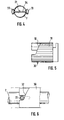
- Fig. 5
- eine Ansicht der hülsenartigen Wendel,
- Fig. 6
- eine Ansicht entsprechend Fig. 3 mit um 90° gedrehtem Drehelement,
- Fig. 7
- eine Seitenansicht eines Längsholms in aufgebauter Fahrgestellstellung,
- Fig. 8
- eine Ansicht gemäß Fig. 7 mit ausgerücktem Rastelement,
- Fig. 9
- das Fahrgestell im zusammengelegten Zustand,
- Fig. 10
- eine Schnittansicht entsprechend Fig. 3 mit betätigtem Schiebeelement zum Lösen der weiteren Rastelemente,
- Fig. 11
- eine Seitenansicht eines Längsholms mit in Raststellung befindlichem weiteren Rastelement,
- Fig. 12
- eine Ansicht entsprechend Fig. 11 mit gelöstem Rastelement, und
- Fig. 13
- eine Seitenansicht eines Kinderwagens mit umgelegtem Schieber.
- Fig. 1
- a perspective view of a stroller according to the invention,
- Fig. 2
- 2 shows a sectional view of a combined part according to the invention, on which a rotating element and a sliding element are combined,
- Fig. 3
- 3 shows a partial sectional view of the part from FIG. 2 fastened to a longitudinal spar,
- Fig. 4
- 3 shows a sectional view in the direction of line IV, IV in FIG. 3,
- Fig. 5
- a view of the sleeve-like coil,
- Fig. 6
- 3 with a rotating element rotated by 90 °,
- Fig. 7
- a side view of a longitudinal spar in the assembled chassis position,
- Fig. 8
- 7 with the detent element disengaged,
- Fig. 9
- the chassis when folded,
- Fig. 10
- 3 shows a sectional view corresponding to FIG. 3 with the sliding element actuated to release the further latching elements,
- Fig. 11
- 2 shows a side view of a longitudinal spar with a further latching element located in the latched position,
- Fig. 12
- a view corresponding to FIG. 11 with the detent element released, and
- Fig. 13
- a side view of a stroller with the slider folded.
Fig. 1 zeigt einen erfindungsgemäßen Kinderwagen 1, bestehend aus einem
Fahrgestell 2, auf welches es im vorliegenden insoweit nicht ankommt, weshalb
dieses nicht näher beschrieben ist. Mit dem Fahrgestell verbunden sind zwei
Scheren 3, 4, die ein Einsatzteil 5 tragen, auf welchem das Kind sitzt. Zum Schieben
ist ein Schieber 6 vorgesehen, der im wesentlichen eine U-Form aufweist.
Das Fahrgestell kann zusammengelegt werden, wie in Fig. 9 gezeigt, daneben
kann der Schieber 6 auch auf die andere Seite geschwenkt werden. Der Schieber
6 selbst weist zwei Längsholme 7, 8 auf, die mittels zweier Befestigungsstreben 9,
10 am Ende eines Schenkels 11, 12 der jeweiligen Scheren 3, 4 angelenkt sind.
Jeder Längsholm 7, 8 ist mit der jeweiligen Befestigungsstrebe über eine Gelenkverbindung
13 (siehe Fig. 7) verbunden. Am unteren Ende jeder Befestigungsstrebe
9, 10 ist ein Rastelement 14 in Form eines Rastzapfens angeordnet, welche
an einer entsprechenden Rastaufnahme 15, 16, die an einem weiteren
Schenkel 17, 18 der Scheren 3, 4 angeordnet ist, aufgenommen. Hierdurch wird
das Fahrgestell in der aufgestellten Form arretiert und gehalten.Fig. 1 shows a
Unter Bezugnahme auf Fig. 7 wird die Bewegungskopplung eines Rastelements
näher erläutert. Das Rastelement 14 ist mit einem am Längsholm 7 angeordneten
hülsenartigen Kopplungsteil 19 lösbar mittels eines am Kopplungsteil 19 angreifenden
Kopplungszapfens 20, welcher mit dem Rastzapfen 14 verbunden ist und
aus der Befestigungsstrebe hervorsteht, verbunden. Das Kopplungsteil 19 wiederum
ist mit einem im Inneren des Längsholms 7 verlaufenden Zugelement 21 in
Form einer Zugstange über eine entsprechende Bolzenverbindung 22 verbunden.
Die Zugstange wiederum kann mittels eines nachfolgend noch beschriebenen
Bewegungsmechanismus im Inneren des Längsholms 7 bewegt werden, so daß
das Kopplungsteil 19 längs des Holmes 7 bewegbar ist (der Bolzen 22 wandert
dann in der Längsdurchbrechung 23), wodurch dann bei Mitnahme des Zapfens
20 das jeweilige Rastelement eingezogen und aus der Rastaufnahme 15 gelöst
werden kann, wie in Fig. 8 gezeigt, so daß die Verrastung aufgehoben wird und,
wie durch den Pfeil A in Fig. 8 dargestellt ist, der Schieber nach unten fallen kann,
wobei die Bewegung durch eine Falle 24, die separat beispielsweise mit dem Fuß
gelöst werden muß, um das Gestell gänzlich zusammenzulegen, gebremst wird.Referring to Fig. 7, the movement coupling of a locking element
explained in more detail. The locking
Der Mechanismus zum Lösen des Rastelements ist im Detail in den Fig. 2 bis 6
beschrieben. Fig. 2 zeigt ein gemeinsames Teil 25, welches am jeweiligen Längsholm
angeordnet ist. Hierzu ist am Teil 25 ein Befestigungsabschnitt 26 ausgebildet,
welcher mittels einer Bolzenverbindung am Holm angebracht wird. Am gemeinsamen
Teil 25 ist ein Drehelement 27 realisiert, welches zum Bewegen der
Rastelemente dient, sowie ein Schiebeelement 28, welches zum Bewegen weiterer
Rastelemente zu betätigen ist, um den Schieber 6 von der einen auf die andere
Seite umlegen zu können, was nachfolgend noch beschrieben wird. Das Teil
25, das, siehe Fig. 3, griffartig den Holm 7 umgibt, weist ein griffartiges Teil 29 auf,
welches zum Bewegen einer im Inneren angeordneten Wendel 30 dient. Diese
Wendel 30, die mit einer Außenverzahnung 31 versehen ist, die mit einer entsprechenden
Innenverzahnung des griffartigen Teils 29 kämmt, ist um die Holmlängsachse
drehbar und weist zwei wendelartig steigende Führungsflächen 32 auf. Auf
diesen Führungsflächen laufen zwei Walzen 33 (siehe Fig. 4), die drehbar an einem
Querstift 34 angeordnet sind, der mit der Zugstange 21 verbunden ist, und
der, siehe Fig. 7, eine entsprechende Längsdurchbrechung 35 am Holm 7 durchsetzt.
Wird nun, ausgehend von der in Fig. 3 gezeigten Ausgangsstellung, das
griffartige Teil 29 um 90° verdreht, so wird automatisch die Wendel 30 gedreht,
was dazu führt, daß die Walzen auf die Führungsfläche 32 "nach oben" laufen,
was gleichzeitig bedeutet, daß das Zugelement 21 angezogen wird, was wiederum
infolge der Bewegungskopplung zum Einziehen des Rastelements 14 führt. The mechanism for releasing the latching element is shown in detail in FIGS. 2 to 6
described. Fig. 2 shows a
Auf diese Weise wird dieses aus seinem Rasteingriff gelöst. Wird das griffartige
Teil 29 losgelassen, so wird es bedingt durch die Rückstellkraft einer nicht näher
gezeigten Torsionsfeder wieder in die in Fig. 3 gezeigte Ausgangsstellung zurückgeführt,
was dazu führt, daß auch der Rastzapfen 14 wieder austritt. Zum Zusammenlegen
ist also eine Drehbewegung erforderlich, die ein unbeabsichtigtes
Betätigen dieses Lösemechanismus ausschließt. Die Drehrichtung der griffartigen
Teile 29 der beiden Holme 7, 8 ist zweckmäßigerweise gegengleich, beide sind
beispielsweise zum Lösen um ca. 90° nach innen zu verdrehen.In this way, this is released from its locking engagement. Will that be
Wie die Fig. 11 bis 13 zeigen ist es darüber hinaus möglich, den Schieber 6 auch
auf die andere Seite umzulegen, was durch Herumschwenken um die Gelenkverbindung
13 erfolgt. Zu diesem Zweck ist, siehe Fig. 11, am Längsholm 7 (gleiches
gilt natürlich auch für den Längsholm 8) ein weiteres Rastelement 36 vorgesehen,
bestehend aus einem Schiebeteil 37 mit einander gegenüberliegenden Rastklauen
38. Die eine Rastklaue 38 steht in Eingriff mit einer Rastaufnahme 39, die im
Bereich des oberen Endes der Befestigungsstrebe 9 ausgebildet ist. Soll nun der
Schieber 6 umgelegt werden, ist dieser Rasteingriff zu lösen, wozu das Schiebeteil
7 mittels eines weiteren Zugelements 40 in Form einer Zugstange mit einem
Schiebeelement 28 verbunden ist. Dieses Schiebeelement ist ebenfalls am gemeinsamen
Teil 25 ausgebildet, das heißt, an diesem ist sowohl das Drehelement
als auch das Schiebeelement vorgesehen. Das Schiebeelement 28 umfaßt, siehe
die Fig. 2 und 3, ein Schiebestück 41, welches den Holm 7 ebenfalls hülsenartig
umgibt. An diesem Schiebestück 41 ist ein Druckknopf 42 vorgesehen, mittels
welchem ein im Holminneren gegen die Wirkung einer Blattfeder 43 gelagerter
Sperrzapfen 44 nach innen drückbar ist. Dieser Sperrzapfen 44 ist Teil einer Sperreinrichtung,
die zum Sperren des Schiebeelements 48 dient, um auf diese Weise
ein unbeabsichtigtes Betätigen desselben zu vermeiden.As shown in FIGS. 11 to 13, it is also possible to slide 6 as well
to flip to the other side, what by swinging around the
Die Betätigung des Schiebeelements wird, ausgehend von der in Fig. 3 gezeigten
Stellung, in Verbindung mit Fig. 10 erläutert. Um das Schiebeelement überhaupt
betätigen zu können, ist zunächst der Druckknopf 42 zu drücken, was dazu führt,
daß der daran anliegende Sperrzapfen 44 in das Holminnere gedrückt wird, siehe
Pfeil C in Fig. 11. Hierdurch wird die Sperre des Schiebeelements 28 aufgehoben,
so daß dieses, siehe Pfeil D in Fig. 11 sowie in Fig. 10 längs des Holmes 7 verschoben
werden kann. Das Schiebestück 41 wird dabei über den Sperrzapfen 44
hinweggeschoben. Dieser wird dadurch nieder gehalten. Gleichzeitig wird auch
das Drehelement 27, also das griffartige Teil 29 und die Wendel 30 mitverschoben.
Lediglich das Befestigungsstück 26 verbleibt unbewegt. Während des Verschiebens
umgreift die Ausnehmung 45 der Wendel 30 die Walzen 33, die ebenfalls
bei Betätigung des Schiebeelements unbewegt bleiben.The actuation of the sliding element is based on that shown in FIG. 3
Position explained in connection with Fig. 10. To the sliding element at all
to be able to operate, the
Infolge der Bewegung des Schiebeelements 28 wird das Zugelement 40, das am
Schiebeteil 41 befestigt ist, angezogen, was dazu führt, daß auch das Schiebestück
37 bewegt wird, siehe Fig. 12, und die Rastklaue 38 außer Eingriff gebracht
wird. Anschließend kann der Schieber 6 um das Drehgelenk 13 geschwenkt werden,
siehe Pfeil E in Fig. 12, und auf die gegenüberliegende Gestellseite geworfen
werden, wo eine entsprechende Rastaufnahme 46 am Ende eines Scherenholmes
47 vorgesehen ist, in die die andere Rastklaue 38 eingreift. Das Schiebeteil
37 selbst, das am Holm 7 mittels einer Bolzenverbindung 48 gehaltert ist, ist mittels
einer nicht gezeigten Feder mit einer Rückstellkraft beauftragt, die das Schiebeteil
37 stets nach unten in Richtung eines Rasteingriffs drängt. Mittels einer Bolzenverbindung
49, die ein Langloch am Schiebestück 41 durchsetzt, ist dieses
unverdrehbar gehaltert.As a result of the movement of the sliding
Claims (17)
Priority Applications (1)
| Application Number | Priority Date | Filing Date | Title |
|---|---|---|---|
| DK99115372T DK0997367T3 (en) | 1998-10-28 | 1999-08-04 | Frame for a stroller or doll |
Applications Claiming Priority (2)
| Application Number | Priority Date | Filing Date | Title |
|---|---|---|---|
| DE29819218U | 1998-10-28 | ||
| DE29819218U DE29819218U1 (en) | 1998-10-28 | 1998-10-28 | Chassis for a pram or doll's pram |
Publications (3)
| Publication Number | Publication Date |
|---|---|
| EP0997367A2 true EP0997367A2 (en) | 2000-05-03 |
| EP0997367A3 EP0997367A3 (en) | 2003-09-10 |
| EP0997367B1 EP0997367B1 (en) | 2004-10-06 |
Family
ID=8064508
Family Applications (1)
| Application Number | Title | Priority Date | Filing Date |
|---|---|---|---|
| EP99115372A Expired - Lifetime EP0997367B1 (en) | 1998-10-28 | 1999-08-04 | Frame for child's or doll's prams |
Country Status (4)
| Country | Link |
|---|---|
| EP (1) | EP0997367B1 (en) |
| AT (1) | ATE278593T1 (en) |
| DE (2) | DE29819218U1 (en) |
| DK (1) | DK0997367T3 (en) |
Cited By (5)
| Publication number | Priority date | Publication date | Assignee | Title |
|---|---|---|---|---|
| EP1238887A3 (en) * | 2001-03-05 | 2003-12-17 | Combi Corporation | Folding stroller |
| US7686322B2 (en) | 2004-04-30 | 2010-03-30 | Chicco Usa, Inc. | Foldable stroller with memory recline |
| USD636300S1 (en) | 2009-08-14 | 2011-04-19 | Artsana Usa, Inc. | Stroller |
| US8262124B2 (en) | 2007-11-01 | 2012-09-11 | Artsana Usa, Inc. | Folding stroller actuating system |
| CN103502080A (en) * | 2011-04-07 | 2014-01-08 | 丰泰斯蒂克有限公司 | Finger guard |
Families Citing this family (6)
| Publication number | Priority date | Publication date | Assignee | Title |
|---|---|---|---|---|
| DE10330207B4 (en) * | 2003-07-03 | 2007-09-27 | Joh. Georg Hartan | Child or doll carriage |
| US8100429B2 (en) | 2008-03-31 | 2012-01-24 | Artsana Usa, Inc. | Three dimensional folding stroller with infant carrier attachment and one hand actuated seat recline |
| PT2323888E (en) | 2008-08-15 | 2015-03-31 | Artsana Usa Inc | Stroller |
| US8240700B2 (en) | 2008-08-15 | 2012-08-14 | Artsana Usa, Inc. | Stroller with travel seat attachment |
| USD651140S1 (en) | 2010-12-20 | 2011-12-27 | Artsana Usa, Inc. | Stroller frame tubing |
| US9855964B2 (en) * | 2016-02-29 | 2018-01-02 | Wonderland Switzerland Ag | Stroller frame |
Family Cites Families (6)
| Publication number | Priority date | Publication date | Assignee | Title |
|---|---|---|---|---|
| US3653681A (en) * | 1970-05-19 | 1972-04-04 | Julian A Virtue | Baby stroller |
| CA1316952C (en) * | 1986-08-22 | 1993-04-27 | Shinroku Nakao | Foldable baby carriage |
| JP2583063B2 (en) * | 1987-06-26 | 1997-02-19 | アップリカ葛西株式会社 | baby carriage |
| EP0494701A3 (en) * | 1987-07-28 | 1992-09-09 | Aprica Kassai Kabushikikaisha | Baby carriage |
| US5205579A (en) * | 1990-10-08 | 1993-04-27 | Combi Corporation | Handle bar for baby carriage |
| GB2319227B (en) * | 1996-11-11 | 2000-09-27 | Huang Li Chu Chen | Foldable mechanisim for a stroller |
-
1998
- 1998-10-28 DE DE29819218U patent/DE29819218U1/en not_active Expired - Lifetime
-
1999
- 1999-08-04 EP EP99115372A patent/EP0997367B1/en not_active Expired - Lifetime
- 1999-08-04 DE DE59910728T patent/DE59910728D1/en not_active Expired - Lifetime
- 1999-08-04 DK DK99115372T patent/DK0997367T3/en active
- 1999-08-04 AT AT99115372T patent/ATE278593T1/en not_active IP Right Cessation
Non-Patent Citations (1)
| Title |
|---|
| None |
Cited By (8)
| Publication number | Priority date | Publication date | Assignee | Title |
|---|---|---|---|---|
| EP1238887A3 (en) * | 2001-03-05 | 2003-12-17 | Combi Corporation | Folding stroller |
| US6893031B2 (en) | 2001-03-05 | 2005-05-17 | Combi Corporation | Folding stroller |
| CN1319796C (en) * | 2001-03-05 | 2007-06-06 | 宫比株式会社 | Folding four-wheel carriages for children |
| KR100852410B1 (en) * | 2001-03-05 | 2008-08-14 | 콤비 가부시키가이샤 | Folding stroller |
| US7686322B2 (en) | 2004-04-30 | 2010-03-30 | Chicco Usa, Inc. | Foldable stroller with memory recline |
| US8262124B2 (en) | 2007-11-01 | 2012-09-11 | Artsana Usa, Inc. | Folding stroller actuating system |
| USD636300S1 (en) | 2009-08-14 | 2011-04-19 | Artsana Usa, Inc. | Stroller |
| CN103502080A (en) * | 2011-04-07 | 2014-01-08 | 丰泰斯蒂克有限公司 | Finger guard |
Also Published As
| Publication number | Publication date |
|---|---|
| ATE278593T1 (en) | 2004-10-15 |
| EP0997367B1 (en) | 2004-10-06 |
| EP0997367A3 (en) | 2003-09-10 |
| DK0997367T3 (en) | 2005-01-03 |
| DE59910728D1 (en) | 2004-11-11 |
| DE29819218U1 (en) | 1999-03-25 |
Similar Documents
| Publication | Publication Date | Title |
|---|---|---|
| EP2957479B1 (en) | Pram chassis and pram | |
| DE60200063T2 (en) | Folding stroller | |
| DE2823086C2 (en) | Stroller with a pushing device that can be adjusted for both directions of travel | |
| EP1762459B1 (en) | Chassis for a pram or a doll's pram as well as a pram or a doll's pram | |
| DE60200441T2 (en) | Triple folding stroller | |
| EP0997367B1 (en) | Frame for child's or doll's prams | |
| DE3237214C2 (en) | Pushing device for prams that can be reversed for both directions of travel | |
| DE102012102531B4 (en) | KINDERWAGEN, ITS FRAMEWORK ASSEMBLY ARRANGEMENT AND METHOD FOR OPERATING THE SAME | |
| DE202010011566U1 (en) | Carrycot | |
| DE1457245C3 (en) | Large hand luggage with wheels | |
| EP3512752A2 (en) | Pushchair chassis and pushchair | |
| DE4229857C2 (en) | Collapsible chassis for a stroller | |
| DE102005029111B4 (en) | Roof rails for vehicles | |
| EP1493646B1 (en) | Stroller for children or dolls | |
| DE69834530T2 (en) | stroller | |
| DE19538080A1 (en) | Transporting device for small boats, surfboards etc. | |
| DE202015001097U1 (en) | stroller | |
| DE3007888C2 (en) | ||
| WO2002034614A1 (en) | Vehicle with a footboard and a collapsible steering pole | |
| DE102017122514B4 (en) | Locking mechanism for locking two side walls of a motor vehicle or a motor vehicle trailer that meet at a corner and pivot relative to one another | |
| EP1491422B1 (en) | Pram with folding mechanism | |
| EP4088985A1 (en) | Baby or doll carriage | |
| DE3050689C2 (en) | Locking device for a folding stroller | |
| DE19938564A1 (en) | Chassis for child's or doll's push chair has arm supports connected to side struts and cross bearer via pivot connection to prevent obstruction when collapsed | |
| EP4088988A1 (en) | Cross-connector for children's or dolls' buggies |
Legal Events
| Date | Code | Title | Description |
|---|---|---|---|
| PUAI | Public reference made under article 153(3) epc to a published international application that has entered the european phase |
Free format text: ORIGINAL CODE: 0009012 |
|
| AK | Designated contracting states |
Kind code of ref document: A2 Designated state(s): AT BE CH CY DE DK ES FI FR GB GR IE IT LI LU MC NL PT SE |
|
| AX | Request for extension of the european patent |
Free format text: AL;LT;LV;MK;RO;SI |
|
| PUAL | Search report despatched |
Free format text: ORIGINAL CODE: 0009013 |
|
| AK | Designated contracting states |
Kind code of ref document: A3 Designated state(s): AT BE CH CY DE DK ES FI FR GB GR IE IT LI LU MC NL PT SE |
|
| AX | Request for extension of the european patent |
Extension state: AL LT LV MK RO SI |
|
| 17P | Request for examination filed |
Effective date: 20031108 |
|
| GRAP | Despatch of communication of intention to grant a patent |
Free format text: ORIGINAL CODE: EPIDOSNIGR1 |
|
| 17Q | First examination report despatched |
Effective date: 20040202 |
|
| AKX | Designation fees paid |
Designated state(s): AT BE CH CY DE DK ES FI FR GB GR IE IT LI LU MC NL PT SE |
|
| GRAS | Grant fee paid |
Free format text: ORIGINAL CODE: EPIDOSNIGR3 |
|
| GRAA | (expected) grant |
Free format text: ORIGINAL CODE: 0009210 |
|
| AK | Designated contracting states |
Kind code of ref document: B1 Designated state(s): AT BE CH CY DE DK ES FI FR GB GR IE IT LI LU MC NL PT SE |
|
| PG25 | Lapsed in a contracting state [announced via postgrant information from national office to epo] |
Ref country code: IT Free format text: LAPSE BECAUSE OF FAILURE TO SUBMIT A TRANSLATION OF THE DESCRIPTION OR TO PAY THE FEE WITHIN THE PRE;WARNING: LAPSES OF ITALIAN PATENTS WITH EFFECTIVE DATE BEFORE 2007 MAY HAVE OCCURRED AT ANY TIME BEFORE 2007. THE CORRECT EFFECTIVE DATE MAY BE DIFFERENT FROM THE ONE RECORDED.SCRIBED TIME-LIMIT Effective date: 20041006 Ref country code: IE Free format text: LAPSE BECAUSE OF FAILURE TO SUBMIT A TRANSLATION OF THE DESCRIPTION OR TO PAY THE FEE WITHIN THE PRESCRIBED TIME-LIMIT Effective date: 20041006 Ref country code: GB Free format text: LAPSE BECAUSE OF FAILURE TO SUBMIT A TRANSLATION OF THE DESCRIPTION OR TO PAY THE FEE WITHIN THE PRESCRIBED TIME-LIMIT Effective date: 20041006 Ref country code: FR Free format text: LAPSE BECAUSE OF NON-PAYMENT OF DUE FEES Effective date: 20041006 |
|
| REG | Reference to a national code |
Ref country code: GB Ref legal event code: FG4D Free format text: NOT ENGLISH |
|
| REG | Reference to a national code |
Ref country code: CH Ref legal event code: NV Representative=s name: ISLER & PEDRAZZINI AG Ref country code: CH Ref legal event code: EP |
|
| REG | Reference to a national code |
Ref country code: IE Ref legal event code: FG4D Free format text: GERMAN |
|
| REG | Reference to a national code |
Ref country code: SE Ref legal event code: TRGR |
|
| REF | Corresponds to: |
Ref document number: 59910728 Country of ref document: DE Date of ref document: 20041111 Kind code of ref document: P |
|
| REG | Reference to a national code |
Ref country code: DK Ref legal event code: T3 |
|
| PG25 | Lapsed in a contracting state [announced via postgrant information from national office to epo] |
Ref country code: GR Free format text: LAPSE BECAUSE OF FAILURE TO SUBMIT A TRANSLATION OF THE DESCRIPTION OR TO PAY THE FEE WITHIN THE PRESCRIBED TIME-LIMIT Effective date: 20050106 |
|
| PG25 | Lapsed in a contracting state [announced via postgrant information from national office to epo] |
Ref country code: ES Free format text: LAPSE BECAUSE OF FAILURE TO SUBMIT A TRANSLATION OF THE DESCRIPTION OR TO PAY THE FEE WITHIN THE PRESCRIBED TIME-LIMIT Effective date: 20050117 |
|
| GBV | Gb: ep patent (uk) treated as always having been void in accordance with gb section 77(7)/1977 [no translation filed] |
Effective date: 20041006 |
|
| REG | Reference to a national code |
Ref country code: IE Ref legal event code: FD4D |
|
| PG25 | Lapsed in a contracting state [announced via postgrant information from national office to epo] |
Ref country code: LU Free format text: LAPSE BECAUSE OF NON-PAYMENT OF DUE FEES Effective date: 20050804 Ref country code: CY Free format text: LAPSE BECAUSE OF FAILURE TO SUBMIT A TRANSLATION OF THE DESCRIPTION OR TO PAY THE FEE WITHIN THE PRESCRIBED TIME-LIMIT Effective date: 20050804 |
|
| PGFP | Annual fee paid to national office [announced via postgrant information from national office to epo] |
Ref country code: FI Payment date: 20050808 Year of fee payment: 7 |
|
| PLBE | No opposition filed within time limit |
Free format text: ORIGINAL CODE: 0009261 |
|
| STAA | Information on the status of an ep patent application or granted ep patent |
Free format text: STATUS: NO OPPOSITION FILED WITHIN TIME LIMIT |
|
| PGFP | Annual fee paid to national office [announced via postgrant information from national office to epo] |
Ref country code: BE Payment date: 20050822 Year of fee payment: 7 |
|
| PGFP | Annual fee paid to national office [announced via postgrant information from national office to epo] |
Ref country code: CH Payment date: 20050823 Year of fee payment: 7 |
|
| PG25 | Lapsed in a contracting state [announced via postgrant information from national office to epo] |
Ref country code: MC Free format text: LAPSE BECAUSE OF NON-PAYMENT OF DUE FEES Effective date: 20050831 |
|
| 26N | No opposition filed |
Effective date: 20050707 |
|
| EN | Fr: translation not filed | ||
| PG25 | Lapsed in a contracting state [announced via postgrant information from national office to epo] |
Ref country code: FI Free format text: LAPSE BECAUSE OF NON-PAYMENT OF DUE FEES Effective date: 20060804 |
|
| PG25 | Lapsed in a contracting state [announced via postgrant information from national office to epo] |
Ref country code: LI Free format text: LAPSE BECAUSE OF NON-PAYMENT OF DUE FEES Effective date: 20060831 Ref country code: CH Free format text: LAPSE BECAUSE OF NON-PAYMENT OF DUE FEES Effective date: 20060831 Ref country code: BE Free format text: LAPSE BECAUSE OF NON-PAYMENT OF DUE FEES Effective date: 20060831 |
|
| REG | Reference to a national code |
Ref country code: CH Ref legal event code: PL |
|
| BERE | Be: lapsed |
Owner name: FIRMA JOH. GEORG *HARTAN Effective date: 20060831 |
|
| PG25 | Lapsed in a contracting state [announced via postgrant information from national office to epo] |
Ref country code: PT Free format text: LAPSE BECAUSE OF NON-PAYMENT OF DUE FEES Effective date: 20050306 |
|
| PGFP | Annual fee paid to national office [announced via postgrant information from national office to epo] |
Ref country code: DK Payment date: 20090826 Year of fee payment: 11 |
|
| PGFP | Annual fee paid to national office [announced via postgrant information from national office to epo] |
Ref country code: NL Payment date: 20090831 Year of fee payment: 11 Ref country code: AT Payment date: 20090813 Year of fee payment: 11 |
|
| REG | Reference to a national code |
Ref country code: NL Ref legal event code: V1 Effective date: 20110301 |
|
| REG | Reference to a national code |
Ref country code: DK Ref legal event code: EBP |
|
| PG25 | Lapsed in a contracting state [announced via postgrant information from national office to epo] |
Ref country code: NL Free format text: LAPSE BECAUSE OF NON-PAYMENT OF DUE FEES Effective date: 20110301 Ref country code: AT Free format text: LAPSE BECAUSE OF NON-PAYMENT OF DUE FEES Effective date: 20100804 |
|
| PG25 | Lapsed in a contracting state [announced via postgrant information from national office to epo] |
Ref country code: DK Free format text: LAPSE BECAUSE OF NON-PAYMENT OF DUE FEES Effective date: 20100831 |
|
| PGFP | Annual fee paid to national office [announced via postgrant information from national office to epo] |
Ref country code: SE Payment date: 20110817 Year of fee payment: 13 |
|
| REG | Reference to a national code |
Ref country code: SE Ref legal event code: EUG |
|
| PG25 | Lapsed in a contracting state [announced via postgrant information from national office to epo] |
Ref country code: SE Free format text: LAPSE BECAUSE OF NON-PAYMENT OF DUE FEES Effective date: 20120805 |
|
| PGFP | Annual fee paid to national office [announced via postgrant information from national office to epo] |
Ref country code: DE Payment date: 20160815 Year of fee payment: 18 |
|
| REG | Reference to a national code |
Ref country code: DE Ref legal event code: R119 Ref document number: 59910728 Country of ref document: DE |
|
| PG25 | Lapsed in a contracting state [announced via postgrant information from national office to epo] |
Ref country code: DE Free format text: LAPSE BECAUSE OF NON-PAYMENT OF DUE FEES Effective date: 20180301 |