EP0996818B1 - Method and arrangement for starting a four-stroke injection engine - Google Patents
Method and arrangement for starting a four-stroke injection engine Download PDFInfo
- Publication number
- EP0996818B1 EP0996818B1 EP98934008A EP98934008A EP0996818B1 EP 0996818 B1 EP0996818 B1 EP 0996818B1 EP 98934008 A EP98934008 A EP 98934008A EP 98934008 A EP98934008 A EP 98934008A EP 0996818 B1 EP0996818 B1 EP 0996818B1
- Authority
- EP
- European Patent Office
- Prior art keywords
- engine
- crankshaft
- camshaft
- signal
- injection
- Prior art date
- Legal status (The legal status is an assumption and is not a legal conclusion. Google has not performed a legal analysis and makes no representation as to the accuracy of the status listed.)
- Expired - Lifetime
Links
- 238000002347 injection Methods 0.000 title claims description 46
- 239000007924 injection Substances 0.000 title claims description 46
- 238000000034 method Methods 0.000 title claims description 11
- 230000004913 activation Effects 0.000 claims description 14
- 230000000903 blocking effect Effects 0.000 claims description 7
- 230000018199 S phase Effects 0.000 claims description 4
- 230000000694 effects Effects 0.000 claims description 3
- 239000000446 fuel Substances 0.000 description 20
- 230000008859 change Effects 0.000 description 6
- 238000012544 monitoring process Methods 0.000 description 5
- 238000007796 conventional method Methods 0.000 description 4
- 238000010586 diagram Methods 0.000 description 4
- 230000006835 compression Effects 0.000 description 3
- 238000007906 compression Methods 0.000 description 3
- 230000006870 function Effects 0.000 description 3
- 239000007858 starting material Substances 0.000 description 3
- 238000005265 energy consumption Methods 0.000 description 2
- 230000009471 action Effects 0.000 description 1
- 230000006978 adaptation Effects 0.000 description 1
- 238000002485 combustion reaction Methods 0.000 description 1
- 230000008878 coupling Effects 0.000 description 1
- 238000010168 coupling process Methods 0.000 description 1
- 238000005859 coupling reaction Methods 0.000 description 1
- 230000006872 improvement Effects 0.000 description 1
- 230000007257 malfunction Effects 0.000 description 1
- 238000004519 manufacturing process Methods 0.000 description 1
- 239000000203 mixture Substances 0.000 description 1
- 230000008569 process Effects 0.000 description 1
- 238000005086 pumping Methods 0.000 description 1
- 230000009467 reduction Effects 0.000 description 1
- 239000000243 solution Substances 0.000 description 1
- 230000001360 synchronised effect Effects 0.000 description 1
Images

Classifications
-
- F—MECHANICAL ENGINEERING; LIGHTING; HEATING; WEAPONS; BLASTING
- F02—COMBUSTION ENGINES; HOT-GAS OR COMBUSTION-PRODUCT ENGINE PLANTS
- F02D—CONTROLLING COMBUSTION ENGINES
- F02D41/00—Electrical control of supply of combustible mixture or its constituents
- F02D41/009—Electrical control of supply of combustible mixture or its constituents using means for generating position or synchronisation signals
-
- F—MECHANICAL ENGINEERING; LIGHTING; HEATING; WEAPONS; BLASTING
- F02—COMBUSTION ENGINES; HOT-GAS OR COMBUSTION-PRODUCT ENGINE PLANTS
- F02D—CONTROLLING COMBUSTION ENGINES
- F02D41/00—Electrical control of supply of combustible mixture or its constituents
- F02D41/02—Circuit arrangements for generating control signals
- F02D41/04—Introducing corrections for particular operating conditions
- F02D41/06—Introducing corrections for particular operating conditions for engine starting or warming up
- F02D41/062—Introducing corrections for particular operating conditions for engine starting or warming up for starting
-
- F—MECHANICAL ENGINEERING; LIGHTING; HEATING; WEAPONS; BLASTING
- F02—COMBUSTION ENGINES; HOT-GAS OR COMBUSTION-PRODUCT ENGINE PLANTS
- F02D—CONTROLLING COMBUSTION ENGINES
- F02D41/00—Electrical control of supply of combustible mixture or its constituents
- F02D41/30—Controlling fuel injection
- F02D41/38—Controlling fuel injection of the high pressure type
- F02D41/40—Controlling fuel injection of the high pressure type with means for controlling injection timing or duration
-
- F—MECHANICAL ENGINEERING; LIGHTING; HEATING; WEAPONS; BLASTING
- F02—COMBUSTION ENGINES; HOT-GAS OR COMBUSTION-PRODUCT ENGINE PLANTS
- F02M—SUPPLYING COMBUSTION ENGINES IN GENERAL WITH COMBUSTIBLE MIXTURES OR CONSTITUENTS THEREOF
- F02M59/00—Pumps specially adapted for fuel-injection and not provided for in groups F02M39/00 -F02M57/00, e.g. rotary cylinder-block type of pumps
- F02M59/38—Pumps characterised by adaptations to special uses or conditions
- F02M59/42—Pumps characterised by adaptations to special uses or conditions for starting of engines
-
- F—MECHANICAL ENGINEERING; LIGHTING; HEATING; WEAPONS; BLASTING
- F02—COMBUSTION ENGINES; HOT-GAS OR COMBUSTION-PRODUCT ENGINE PLANTS
- F02D—CONTROLLING COMBUSTION ENGINES
- F02D41/00—Electrical control of supply of combustible mixture or its constituents
- F02D41/30—Controlling fuel injection
- F02D41/38—Controlling fuel injection of the high pressure type
- F02D2041/389—Controlling fuel injection of the high pressure type for injecting directly into the cylinder
-
- Y—GENERAL TAGGING OF NEW TECHNOLOGICAL DEVELOPMENTS; GENERAL TAGGING OF CROSS-SECTIONAL TECHNOLOGIES SPANNING OVER SEVERAL SECTIONS OF THE IPC; TECHNICAL SUBJECTS COVERED BY FORMER USPC CROSS-REFERENCE ART COLLECTIONS [XRACs] AND DIGESTS
- Y02—TECHNOLOGIES OR APPLICATIONS FOR MITIGATION OR ADAPTATION AGAINST CLIMATE CHANGE
- Y02T—CLIMATE CHANGE MITIGATION TECHNOLOGIES RELATED TO TRANSPORTATION
- Y02T10/00—Road transport of goods or passengers
- Y02T10/10—Internal combustion engine [ICE] based vehicles
- Y02T10/40—Engine management systems
Definitions
- the present invention relates to a method and a four-stroke combustion engine in accordance with the preamble to patent claims 1 and 3 respectively. (Compare with DE-A-4 143 054 & SE-B-46 77 03.)
- Multi-cylinder four-stroke diesel engines have traditionally been equipped with a fuel injection pump which is mechanically connected via a set of gearwheels to the engine's crankshaft from which the pump receives its drive.
- the fuel injection pump has pumped fuel at high pressure via a number of lines out to the injection orifices of each cylinder.
- the engine and the fuel injection pump have been synchronised so that injection can take place in the right cylinder at the right time and that a correct fuel injection sequence is thereby achieved.
- the development of fuel injectors has resulted in there now being types which consist of an injector with a more or less integrated pump.
- each fuel injector is instead supplied by a separate pump element in the vicinity of the injection orifice.
- These new types of fuel injector make it possible to adjust considerably more accurately than previously the fuel injection in each cylinder.
- These new types of fuel injector lack, however, any mechanical coupling between the fuel injection pump and the engine's crankshaft such as has traditionally been used. This means that the synchronisation of the fuel injectors and the crankshaft, which defines the position of the pistons in the engine's cylinders, has to be determined in a different manner.
- crankshaft sensors usually incorporate a sensor on the crankshaft and a sensor on the engine s camshaft.
- the crankshaft sensor is used for defining the position of the pistons, but these sensors cannot unambiguously define which stroke a cylinder is in. Determining this also requires a sensor on the camshaft, which unambiguously defines which strokes the engine's respective cylinders are in.
- a disadvantage of camshaft sensors is that their accuracy of resolution is considerably inferior to that of the crankshaft sensor. For these reasons, engines with these fuel injection systems are provided with an electronic control system which uses the camshaft signal for determining the engine's working strokes and the crankshaft sensor for determining more accurately when the injection in each cylinder should take place.
- a problem in this respect is that when the engine is being started the control system knows nothing about which positions the cylinders are in and which working strokes they are in. This makes it impossible to determine a correct injection sequence.
- the control system thus has to wait for signals from both the crankshaft sensor and the camshaft sensor before a correct injection sequence can be definitely established. This entails the engine having to be turned a relatively large number of times.
- Adjustment of fuel injection can be achieved by electrical control of a throttle valve on the fuel line from the respective injector.
- the method and arrangements according to a known technique for these more modern engines thus use speed indicating signals from the engine's camshaft and signals from the engine's crankshaft for controlling the constriction or blocking of the bleed circuit so that it takes place at the intended phase position and in step with pump injector activation.
- the engine thus provides the control circuit with two speed indicating signals, of which that from the crankshaft is an incremental signal, a pulse train, but with one extra phase position indication per turn, while the camshaft signal takes the form of a pulse train with one phase position indication per camshaft turn.
- the camshaft speed corresponds to half the crankshaft speed, so its phase position indication is usable for determining the correct phase position for the four-stroke engine, i.e.
- phase position indication pertaining to the camshaft when the phase position indication pertaining to the camshaft is detected it shows which phase the four-stroke engine is in, and in the case of two or more cylinders the phase position for each of the engine's cylinders is shown by means of this indication as soon as the camshaft's phase position indication is detected by a detector belonging to the control circuit.
- crankshaft's signal in principle establishes only the piston's position in the cylinder without being able to indicate, for example, whether the cylinder is in a compression phase or an exhaust phase.
- injection is effected by means of a pump injector which is driven by a camshaft and is connected to a fuel supply line and to a bleed circuit (return circuit) for removing surplus fuel.
- the pump injector is acted upon by its associated cam while at the same time the flow through the bleed circuit is constricted by means of a throttle valve (situated in that circuit) which is provided with a signal in the constricting direction from the control circuit, with the combined result that a weighed quantity of fuel is injected into the cylinder space.
- the conventional method thus means that the first injection can only take place after up to two turns of the engine, which is troublesome from the energy and time points of view and hence constitutes a substantial disadvantage.
- the objects of the present invention are to eliminate the problems associated with the prior art and to indicate a method and an arrangement which markedly shorten starting time.
- the invention achieves substantially reduced starting time for a four-stroke injection engine because the control system need not wait for the camshaft signal before setting in motion the injection and hence the engine starting process. Instead, as the control circuit only needs to wait for the crankshaft signal, the average time to first injection for starting the engine will be substantially halved. This represents a major improvement and entails great advantages with regard to energy consumption for running the starter motor as well as a marked reduction in starting time and hence quicker starting of the engines concerned.
- One aspect of the invention refers therein to the operating reliability of the system in the event of failure or error of the camshaft signal, since in such situations the engine can be run even when the control system only receives a (correct) signal from the engine's crankshaft.
- This aspect is further improved if the control system is arranged to monitor the engine's correct phase position and on that basis the control circuit either continues to operate in accordance with the phase position assumed or alters by one crankshaft turn the timing of the constriction or blocking of the bleed circuit.
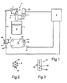
- the reference 1 denotes a cylinder for a four-stroke injection engine and the reference 2 a piston movable in the cylinder.
- the engine may for example take the form of a multi-cylinder diesel engine intended for a heavy-duty vehicle.
- Injection to the cylinder is controlled by a control unit 3 which receives information from detectors 16 and 17 which detect indicating devices belonging respectively to the camshaft 9 and the crankshaft 15.
- An injection unit 4 arranged at the upper part of the cylinder 1 includes a pump injector 5 which itself contains a pump piston 6 movable in a pump housing 10.
- the pump piston 6 is acted upon by a rocker arm 7 which is itself acted upon via a pushrod 8 by a cam 9' arranged on the engine's camshaft 9.
- the pump housing 10 has leading to it a fuel feed line 11 and has leading from it a line belonging to a bleed circuit 12 in which a controllable throttle valve 13 is installed. Activation of the throttle valve 13 so that it constricts or blocks the bleed circuit 12 makes injection to the cylinder 1 possible at the same time as the pump piston 6 is acted upon by means of the cam 9'.
- Fig.2 shows in more detail the indicating arrangement which belongs to the camshaft 9 and which exhibits indicating elements 18 distributed over its periphery, with a rotational position indicating element 18' which in practice takes the form of a double indicating element 18.
- Fig.3 shows a detail of a flywheel 14 arranged on a crankshaft 15, with indicating devices 19 which in this case take the form of a multiplicity of holes evenly distributed circumferentially in the shell surface of the flywheel.
- the reference 19' denotes a rotational position indication represented quite simply by the local omission of an indicating device 19 at one point per turn.
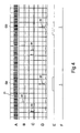
- Fig.4 thus depicts a number of signals relevant to the invention as a function of the angular position of a four-stroke injection engine
- A is a flywheel signal on which each pulse or, in the diagram, each pulse line 21 indicates a tooth of the starting sprocket, i.e. a different solution from that depicted in Fig.3.
- B denotes a so-called trigger signal from the flywheel generated by a tooth arranged separately from the aforesaid sprocket, meaning that the line 22 represents one pulse for each crankshaft turn.
- C is the camwheel signal whereby 23 represents passing the detector of an indicating element and 24 represents passing the detector of the double indicating element.
- D represents activation of the injector for the respective cylinder whereby the pointed crests 25 each represent an electrical pulse delivered from the control system of the arrangement to the throttle valve to activate the latter.
- E denotes activation of the pump piston and F the injection actually effected.
- the crankshaft in a four-stroke engine rotates two turns to perform one cycle of the engine, which means that the position of the crankshaft can only be used for describing the position of the piston in the cylinder but not for definitely describing which phase (e.g. compression or exhaust) the engine is in.
- the trigger signal related to the crankshaft speed is used to activate the throttle valve and hence create the conditions required for injection if the pump piston is also activated.
- the invention is easiest to describe on the basis of Fig.4 in which on the extreme left of the diagram the engine is turned by the starter motor being started.
- the occurrence of the trigger signal 22 provides an immediate indication in the control unit as to the piston position in each of the cylinders that form part of the respective four-stroke engine. As above, however, it gives no definite indication of the phase position which the engine is in.
- the throttle valve now activated soonest after the trigger signal 22 has been received is that pertaining to the cylinder which soonest after the trigger signal has been received has a piston whose position in it corresponds to the position in which injection to the cylinder should take place. At this stage an electrical pulse 25 is thus delivered to the appropriate throttle valve.
- the invention is of course suitable for four-stroke injection engines with more than one cylinder irrespective of whether the number of cylinders is odd or even.
- activation of the throttle valve will always take place simultaneously in the two cylinders which are furthest apart in phase, i.e. in counterphase.
- the actual injection will only take place in whichever of these two cylinders does at the same time have its pump piston acted upon by its associated cam.
- the latter do not operate in counterphase and the activation of the various throttle valves, as also the actual injection, will take place in sequence.
- Fig.4 also illustrates the advantages of the invention relative to the conventional technique which involves having to wait not only for the crankshaft trigger signal 22 but also for the camshaft signal 24 before the control system can begin to activate the throttle valve and hence the actual injection.
- An example which may be mentioned is that in a two-cylinder diesel engine the first actual injection will take place at the first pulse indication for F in an engine which includes an arrangement according to the invention, whereas with the conventional technique in the same two-cylinder four-stroke engine the first injection will take place at the pulse depicted in broken lines on the right against F, i.e. there will be a delay of a whole turn before the first injection takes place.
- Corresponding differences do of course arise with engines which have a different number of cylinders.
- Fig.5 shows a logical block diagram of a method according to the invention whereby block 30 denotes starting of the starter motor, 31 monitoring that the crankshaft trigger signal is received, 32 the emission of an electrical pulse to the throttle valve, 33 monitoring that the camshaft trigger signal is received, 34 adaptation to correct phase position, 35 monitoring of phase position, 36 monitoring of the engine's operating parameters, 37 change of phase position setting, 38 continued operation with assumed phase position and 39 emergency operation on the basis of the camshaft signal.
- block 30 denotes starting of the starter motor
- 31 monitoring that the crankshaft trigger signal is received
- 32 the emission of an electrical pulse to the throttle valve
- 33 monitoring that the camshaft trigger signal is received
- 34 adaptation to correct phase position 35 monitoring of phase position
- 36 monitoring of the engine's operating parameters
- 37 change of phase position setting 38 continued operation with assumed phase position and 39 emergency operation on the basis of the camshaft signal.
- control system according to the invention may optionally include facilities for emergency operation even if the crankshaft signal fails or is faulty. In such cases emergency operation is conducted entirely on the basis of the camshaft signal.
Landscapes
- Engineering & Computer Science (AREA)
- Chemical & Material Sciences (AREA)
- Combustion & Propulsion (AREA)
- Mechanical Engineering (AREA)
- General Engineering & Computer Science (AREA)
- Electrical Control Of Air Or Fuel Supplied To Internal-Combustion Engine (AREA)
- Combined Controls Of Internal Combustion Engines (AREA)
- Fuel-Injection Apparatus (AREA)
- Control Of Vehicle Engines Or Engines For Specific Uses (AREA)
Description
- Fig. 1
- shows schematically an arrangement according to the invention in connection with a four-stroke injection engine,
- Fig.2
- shows an indicating wheel for a camshaft,
- Fig.3
- shows a detail of a flywheel with indicating devices,
- Fig.4
- illustrates crankshaft and camshaft signals to the throttle valve, and
- Fig.5
- shows schematically a block diagram of an arrangement according to the invention.
In more detail, the following applies for operation in cases where the camshaft trigger signal is faulty or has simply failed completely. In such cases operation may continue as above, i.e. with activation of the throttle valve once for each crankshaft turn, but as this is undesirable, inter alia because of unnecessarily large electrical energy consumption, it is desirable to be able to change over to a form of operation whereby the throttle valve is activated in step with pump piston activation (this also applies generally for changing over to normal operation as above). This is achieved according to a further development of the invention by the control unit assuming that a certain phase position prevails in the cylinders, resulting instead in the throttle valve being activated once every second crankshaft turn. Thereafter the engine's operating parameters are monitored and if they change, e.g. through speed decrease, change in exhaust composition etc., this may be taken as indicating that the assumption was incorrect, whereupon it is corrected by the assumed phase position being shifted 360°. If the aforesaid monitoring of the engine's operating parameters detects no change, operation continues with the assumed phase position.
Claims (4)
- Method for starting a four-stroke injection engine of the kind which has a pump injector (5), wherein in normal operation a bleed circuit (12) connected to the pump injector is constricted or blocked in step with the pump injector being activated in order in conjunction with the latter to effect injection to the respective cylinder (1) in accordance with speed indicating signals received from the engine's camshaft (9) and crankshaft (15), characterised in that while the engine is being started and its phase position has not yet been verified by the camshaft signal, only the signals from the crankshaft are used for effecting constriction or blocking of the bleed circuit (12) once each turn of the crankshaft (15) for the respective cylinder, and in that normal control whereby the bleed circuit (12) is constricted or blocked in step with activation of the pump injector (5) once every second crankshaft turn is activated at the earliest after the engine's phase position has been verified by the camshaft signal.
- Method according to claim 1, characterised in that after a predetermined period of time after starting the camshaft signal is monitored and that in the event of failure or error of that signal operation continues on the basis of the crankshaft signal.
- Four-stroke engine (1,2) of the kind which has a pump injector (5), wherein a bleed circuit (12) connected to the pump injector via a control circuit (3) is arranged so that in normal operation it is constricted or blocked in step with pump injector activation in order in conjunction with the latter to effect injection to the respective cylinder (1) in accordance with speed indicating signals received from the engine's camshaft (9) and crankshaft (15), characterised in that while the engine is being started, only the signals from the crankshaft (15) are arranged to be used by the control circuit (3) for constricting or blocking the bleed circuit at each turn of the crankshaft until the engine's phase position has been verified by the camshaft signal, and in that normal control whereby the bleed circuit is constricted or blocked in step with pump injector activation once every second crankshaft turn is arranged to be activated at the earliest after the engine's phase position has been verified by the camshaft signal.
- Engine according to claim 3, characterised in that the control system (3) is arranged so that after a predetermined period of time after starting it monitors the camshaft signal and in the event of failure or error of that signal it causes operation to continue on the basis of the crankshaft signal.
Applications Claiming Priority (3)
| Application Number | Priority Date | Filing Date | Title |
|---|---|---|---|
| SE9702633 | 1997-07-08 | ||
| SE9702633A SE513462C2 (en) | 1997-07-08 | 1997-07-08 | Method and apparatus for starting a four-stroke injection engine |
| PCT/SE1998/001252 WO1999002838A1 (en) | 1997-07-08 | 1998-06-26 | Method and arrangement for starting a four-stroke injection engine |
Publications (2)
| Publication Number | Publication Date |
|---|---|
| EP0996818A1 EP0996818A1 (en) | 2000-05-03 |
| EP0996818B1 true EP0996818B1 (en) | 2003-08-13 |
Family
ID=20407682
Family Applications (1)
| Application Number | Title | Priority Date | Filing Date |
|---|---|---|---|
| EP98934008A Expired - Lifetime EP0996818B1 (en) | 1997-07-08 | 1998-06-26 | Method and arrangement for starting a four-stroke injection engine |
Country Status (6)
| Country | Link |
|---|---|
| EP (1) | EP0996818B1 (en) |
| JP (1) | JP2002508051A (en) |
| BR (1) | BR9810374A (en) |
| DE (1) | DE69817184T2 (en) |
| SE (1) | SE513462C2 (en) |
| WO (1) | WO1999002838A1 (en) |
Families Citing this family (1)
| Publication number | Priority date | Publication date | Assignee | Title |
|---|---|---|---|---|
| JP7115399B2 (en) * | 2019-04-10 | 2022-08-09 | トヨタ自動車株式会社 | Internal combustion engine controller |
Family Cites Families (4)
| Publication number | Priority date | Publication date | Assignee | Title |
|---|---|---|---|---|
| SE467703B (en) * | 1990-12-27 | 1992-08-31 | Volvo Ab | DEVICE FOR ELECTRONIC CONTROL OF BRAIN INJECTORS |
| DE4310460C2 (en) * | 1993-03-31 | 2003-12-18 | Bosch Gmbh Robert | Encoder arrangement for fast cylinder recognition in a multi-cylinder internal combustion engine |
| EP0640762B1 (en) * | 1993-08-26 | 1996-10-23 | Siemens Aktiengesellschaft | Cylinder synchronization of a multi-cylinder internal combustion engine via detection of a directed misfire |
| ITBO940239A1 (en) * | 1994-05-23 | 1995-11-23 | Weber Srl | ELECTRONIC SYSTEM FOR IDENTIFICATION OF THE PHASES OF AN INTERNAL ICE ENGINE. |
-
1997
- 1997-07-08 SE SE9702633A patent/SE513462C2/en not_active IP Right Cessation
-
1998
- 1998-06-26 JP JP50852599A patent/JP2002508051A/en active Pending
- 1998-06-26 BR BR9810374-1A patent/BR9810374A/en unknown
- 1998-06-26 DE DE69817184T patent/DE69817184T2/en not_active Expired - Lifetime
- 1998-06-26 EP EP98934008A patent/EP0996818B1/en not_active Expired - Lifetime
- 1998-06-26 WO PCT/SE1998/001252 patent/WO1999002838A1/en not_active Ceased
Also Published As
| Publication number | Publication date |
|---|---|
| EP0996818A1 (en) | 2000-05-03 |
| WO1999002838A1 (en) | 1999-01-21 |
| JP2002508051A (en) | 2002-03-12 |
| DE69817184D1 (en) | 2003-09-18 |
| SE9702633L (en) | 1999-01-09 |
| SE9702633D0 (en) | 1997-07-08 |
| BR9810374A (en) | 2005-03-22 |
| DE69817184T2 (en) | 2004-06-17 |
| SE513462C2 (en) | 2000-09-18 |
Similar Documents
| Publication | Publication Date | Title |
|---|---|---|
| US5678521A (en) | System and methods for electronic control of an accumulator fuel system | |
| EP0681100B1 (en) | System and methods for electronic control of an accumulator fuel system | |
| CN101749132B (en) | Solenoid diagnostic systems for cylinder deactivation control | |
| US9371794B2 (en) | Method and control unit for controlling an internal combustion engine | |
| KR101775387B1 (en) | Method and control unit for controlling an internal combustion engine | |
| US7007676B1 (en) | Fuel system | |
| US7308880B2 (en) | Starting device for internal combustion engine | |
| US5860406A (en) | Engine timing apparatus and method of operating same | |
| US5105788A (en) | Fuel injection system for an internal-combustion engine | |
| US6433539B2 (en) | Increment transducer and absolute angle transducer means for redundant reliable angular position detection and detection method using same | |
| JP4456787B2 (en) | Apparatus and method for recognizing and influencing a phase position in an internal combustion engine | |
| US5864055A (en) | Method and unit for diagnosing malfunctioning of the injectors of an internal combustion engine high-pressure injection system | |
| SE467703B (en) | DEVICE FOR ELECTRONIC CONTROL OF BRAIN INJECTORS | |
| CA2419184C (en) | Method and device for controlling an internal combustion engine | |
| US5188081A (en) | Control system for a fuel pump | |
| JP3442388B2 (en) | Cylinder detection method for idling of internal combustion engine | |
| EP0996818A1 (en) | Method and arrangement for starting a four-stroke injection engine | |
| JPS6098146A (en) | Fuel control method of internal-combustion engine | |
| US4498444A (en) | Method of controlling engine | |
| US20090139488A1 (en) | Diagnostic system for high pressure fuel system | |
| US6546911B1 (en) | Default methodology for recovering from loss of high resolution engine position signal | |
| JP2836282B2 (en) | Fuel injection device | |
| EP1426597A1 (en) | Hardware architecture of a managing system for start-up and injection phase in an internal combustion engine | |
| EP0412506A1 (en) | Fuel injection control apparatus of internal combustion engine | |
| JPH08105349A (en) | Fuel injection amount control device for diesel engine |
Legal Events
| Date | Code | Title | Description |
|---|---|---|---|
| PUAI | Public reference made under article 153(3) epc to a published international application that has entered the european phase |
Free format text: ORIGINAL CODE: 0009012 |
|
| 17P | Request for examination filed |
Effective date: 20000208 |
|
| AK | Designated contracting states |
Kind code of ref document: A1 Designated state(s): DE FR GB |
|
| GRAH | Despatch of communication of intention to grant a patent |
Free format text: ORIGINAL CODE: EPIDOS IGRA |
|
| GRAH | Despatch of communication of intention to grant a patent |
Free format text: ORIGINAL CODE: EPIDOS IGRA |
|
| GRAA | (expected) grant |
Free format text: ORIGINAL CODE: 0009210 |
|
| AK | Designated contracting states |
Designated state(s): DE FR GB |
|
| PG25 | Lapsed in a contracting state [announced via postgrant information from national office to epo] |
Ref country code: FR Free format text: LAPSE BECAUSE OF NON-PAYMENT OF DUE FEES Effective date: 20030813 |
|
| REG | Reference to a national code |
Ref country code: GB Ref legal event code: FG4D |
|
| REF | Corresponds to: |
Ref document number: 69817184 Country of ref document: DE Date of ref document: 20030918 Kind code of ref document: P |
|
| PLBE | No opposition filed within time limit |
Free format text: ORIGINAL CODE: 0009261 |
|
| STAA | Information on the status of an ep patent application or granted ep patent |
Free format text: STATUS: NO OPPOSITION FILED WITHIN TIME LIMIT |
|
| PG25 | Lapsed in a contracting state [announced via postgrant information from national office to epo] |
Ref country code: GB Free format text: LAPSE BECAUSE OF NON-PAYMENT OF DUE FEES Effective date: 20040626 |
|
| 26N | No opposition filed |
Effective date: 20040514 |
|
| EN | Fr: translation not filed | ||
| GBPC | Gb: european patent ceased through non-payment of renewal fee |
Effective date: 20040626 |
|
| PGFP | Annual fee paid to national office [announced via postgrant information from national office to epo] |
Ref country code: DE Payment date: 20170621 Year of fee payment: 20 |
|
| REG | Reference to a national code |
Ref country code: DE Ref legal event code: R071 Ref document number: 69817184 Country of ref document: DE |