EP0996555B1 - Pivotable arm rest with retaining spring - Google Patents
Pivotable arm rest with retaining spring Download PDFInfo
- Publication number
- EP0996555B1 EP0996555B1 EP99921683A EP99921683A EP0996555B1 EP 0996555 B1 EP0996555 B1 EP 0996555B1 EP 99921683 A EP99921683 A EP 99921683A EP 99921683 A EP99921683 A EP 99921683A EP 0996555 B1 EP0996555 B1 EP 0996555B1
- Authority
- EP
- European Patent Office
- Prior art keywords
- armrest
- retaining member
- recited
- resilient retaining
- armrest assembly
- Prior art date
- Legal status (The legal status is an assumption and is not a legal conclusion. Google has not performed a legal analysis and makes no representation as to the accuracy of the status listed.)
- Expired - Lifetime
Links
- 239000006260 foam Substances 0.000 description 3
- 238000009434 installation Methods 0.000 description 3
- 239000000463 material Substances 0.000 description 3
- 238000012986 modification Methods 0.000 description 2
- 230000004048 modification Effects 0.000 description 2
- 230000000717 retained effect Effects 0.000 description 2
- 229910000639 Spring steel Inorganic materials 0.000 description 1
- 229910000831 Steel Inorganic materials 0.000 description 1
- 230000000712 assembly Effects 0.000 description 1
- 238000000429 assembly Methods 0.000 description 1
- 239000010985 leather Substances 0.000 description 1
- 230000014759 maintenance of location Effects 0.000 description 1
- 238000000034 method Methods 0.000 description 1
- 239000002991 molded plastic Substances 0.000 description 1
- 230000000087 stabilizing effect Effects 0.000 description 1
- 239000010959 steel Substances 0.000 description 1
- 125000000391 vinyl group Chemical group [H]C([*])=C([H])[H] 0.000 description 1
- 229920002554 vinyl polymer Polymers 0.000 description 1
Images

Classifications
-
- B—PERFORMING OPERATIONS; TRANSPORTING
- B60—VEHICLES IN GENERAL
- B60N—SEATS SPECIALLY ADAPTED FOR VEHICLES; VEHICLE PASSENGER ACCOMMODATION NOT OTHERWISE PROVIDED FOR
- B60N2/00—Seats specially adapted for vehicles; Arrangement or mounting of seats in vehicles
- B60N2/75—Arm-rests
- B60N2/753—Arm-rests movable to an inoperative position
Definitions
- This application relates to a unique mounting apparatus for pivotally securing an armrest to a vehicle seat assembly.
- armrests are attached to a side of a vehicle seat back. These armrests pivot between a raised or stowed position and a lowered position. In the raised position, the armrest usually is aligned vertically with the seat back. This stows the armrest out of the way of vehicle occupants to facilitate movement about a vehicle's passenger compartment. When in the lowered or operable use position, the armrest extends horizontally outwardly from the seat back and provides a support for the seat occupant's arm.
- an armrest can be attached to a seat assembly.
- One known attachment method requires the armrest to have a hole extending through its width. A bolt is inserted through the hole for attaching of the armrest to the seat frame. A cap typically covers the hole once the armrest is attached to the seat back, but this leaves an unsightly mark on the exterior surface of the armrest, which can be seen by occupants.
- many known armrests have a significant amount of mounting hardware that is required to install an armrest onto a seat assembly. When many parts are used to mount the armrest to the seat it also increases labor time and cost.
- EP-A-0 002 657 (corresponding to the preamble of claim 1) describes an armrest that is attached to a tubular support shaft.
- the support shaft is fitted into a corresponding bore in the armrest with the support shaft retained in the bore by means of a resilient locking ring engaging corresponding annular grooves at the end of the support shaft and towards the bottom of bore.
- This arrangement may provide for sufficient retention of the armrest in this described arrangement, however the described armrest is not pivotally mounted and is specifically fixed in position by further projections in the end of the shaft which engage slots in the bottom of the bore.
- This armrest is not directed to use with a vehicle seat assembly with its particular requirements nor where access, and so a pivotal mounting, is required. Furthermore the installation of the locking ring within the annular groove in the bore is relatively difficult and time consuming during production line assembly.
- an armrest that is easy to assemble onto a vehicle seat assembly and that reduces the required number of parts and the amount of labor necessary for installation. It is also desirable to have an aesthetically improved armrest that presents an unmarked external surface.
- a vehicle seat assembly typically includes a cushioned seat back that is supported on a cushioned seat bottom.
- the seat back includes an armrest that can pivot relative to the seat back between stowed and operable positions. In the stowed position the armrest is vertically aligned with the seat back and in the operable position the armrest extends generally outwardly from the seat back so that a user can rest their arm on the armrest while sitting in the seat.
- the armrest is preferably received by a support rod that extends outwardly from one side of the seat back.
- an armrest assembly as described in claim 1. Further features of the assembly are set forth in the accompanying claims 2 to 10. There is also provided a vehicle seat assembly including such an armrest assembly as further descrided in claims 11 to 12.
- a vehicle seat assembly in a preferred embodiment of this invention, includes a seat bottom, a seat back supported on the seat bottom, and an armrest pivotally attached to the seat back.
- the armrest has a substantially rigid insert member and a resilient retaining member. The resilient retaining member engages both the insert member and a portion of the seat back to secure the insert member and thus, the armrest, to the seat back.
- This invention offers several advantages over prior art systems because it reduces the number of parts required to attach the armrest to the seat back and also reduces the amount of labor required for installation. Also, an armrest designed according to this invention provides an unmarked exterior surface for the armrest.
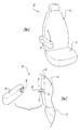
- a vehicle seat assembly is shown generally at 10.
- the seat assembly is installed in a vehicle (not shown) in a conventional manner and includes a seat bottom 12 and a seat back 14 that is supported on the seat bottom 12.
- An armrest 16 is pivotally attached to the seat back 14.
- the armrest 16 can pivot with respect to the seat back 14 between a stowed (non-use) position and an operable (use) position.
- the armrest 16 In the stowed or non-use position the armrest 16 is pivoted so that it is substantially, vertically aligned with the seat back 14. In this position a vehicle driver or passenger can enter or exit the seat 10 without experiencing interference with the armrest 16. In the operable or use position the armrest 16 extends generally outwardly from the seat back 14 so that a driver or passenger can rest their arm on the armrest 16 while sitting on the seat bottom 12. The armrest 16 also can be easily pivoted out of the way if the passenger does not want to use it while sitting in the seat 10.
- the armrest 16 is supported on the seat back 14 by a support rod 18, shown in Figure 2.
- the support rod 18 extends outwardly from one side 20 of the seat back 14 and includes a generally cylindrical body portion 22 with a groove 24 near one end 26.
- the support rod 18 is a stud that is attached to the seat frame (not shown) with one end extending generally perpendicularly from the side 20 of the seat back 14, however, other support members known in the art could also be used.
- the armrest includes a substantially rigid insert member 28 or armature.
- the insert member 28 is preferably made from molded plastic, but other materials such as steel, can be used.
- the insert member 18 is pressed onto the support rod 18 and secured to the seat back 14 so that the armrest 16 cannot be easily detached from the seat back 14.
- the armrest 16 further includes a resilient retaining member 30, shown in Figure 3, that engages the insert member 28 and a portion of the seat back 14 to secure the insert member 28 to the seat back 14.
- the resilient retaining member 30 preferably engages the support rod 18. At least a portion of the support rod 18 is received in the insert member 28 and slidably engages the resilient retaining member 30 to secure the armrest 16 to the seat back 14.
- the insert member 28 is comprised of a body 32 and a retainer portion 34.
- the body 32 is integrally formed with the retainer portion 34 as one piece.
- the body 32 and retainer portion 34 together form a channel 36 that receives the resilient retaining member 30.
- the retainer portion 34 includes a substantially flat portion 38 that is generally parallel to a surface 40 on body 32.
- the retainer portion 34 further includes a plurality of support members 42 that support the flat portion 38 apart from the surface 40 of the body 32 such that a gap 44 is formed between the surface 40 of the body 32 and the flat portion 38.
- the resilient retaining member 30 is preferably installed into the insert member 28 by being slid through the channel 36 and into the gap 44.
- the armrest 16 is then installed on to the support rod 28 of the seat back 14 such that the resilient retaining member 30 secures the support rod 28 to the insert member 28.
- the insert member 28 also preferably includes an inclined portion 46, shown in Figure 4.
- the inclined portion 46 can be located on the surface 40 of the body 32 or on the retainer portion 34.
- the inclined portion 46 is located on the surface 40 of the body 32 and slopes toward the flat portion 38.
- the inclined portion 46 terminates adjacent to one of the support members 42, forming a retaining pocket 48. After the resilient retaining member 30 is inserted into the gap 44, a portion of the retaining member 30 is received in the retaining pocket 48, which prevents the resilient retaining member 30 from later being removed from the gap 44.
- the body 32 includes a first opening 50 and the retainer portion 34 includes a second opening 52.
- the first 50 and second 52 openings are aligned with each other so that they are able to receive the support rod 18.
- the openings 50, 52 are preferably round so that the armrest 16 can easily pivot on the support rod 18.
- the first 50 and second 52 openings have predetermined diameters that are slightly greater than a diameter of the support rod 18.
- the resilient retaining member 30 preferably is a spring that includes a central base portion 54, a pair of spring arms 56, and a pair of spring ends 58.
- the spring arms 56 are flexible and extend radially inwardly towards each other from the central base portion 54.
- the spring arms 56 terminate at the spring ends 58 which extend away from the central base portion 54.
- the resilient retaining member is a generally U-shaped piece with inwardly deflecting spring arms 56 that terminate at diverging spring ends 58.
- the resilient retaining member 30, is preferably made from a spring steel, however, other materials can be used.
- the retainer portion 34 preferably has three (3) support members 42 spaced apart from one another around a circumference of the opening 52.
- the central base portion 54 is received against one of the support members 42, shown in Figure 4.
- each of the spring ends 58 are received against one of the other two support members 42. This configuration securely holds the resilient spring member 30 in the insert member 28.
- the spring arms 56 are biased toward each other and spaced apart from one another by a distance "d" that is less than the diameters of the openings 50, 52. This means that the spring arms 56 deflect outwardly as support rod 18 is inserted into the insert member 28. Specifically, as armrest 16 is pushed onto the support rod 28, the cylindrical body portion 22 of the support rod is inserted through the openings 50, 52 in the insert member 28 causing the spring arms 56 to flex outwardly. The spring arms 56 slide along the cylindrical body portion 22 of the support rod 18 until they reach the groove 24. The spring arms 56 retract inwardly into the groove 24 and lock the support rod 18 into place.
- This attachment allows the armrest 16 to easily pivot with respect to the seat back 14 while being securely held in place by the insert member 28 and resilient retaining member 30.
- the bias on the spring arms 56 also provides a stabilizing effect, which assists in maintaining the armrest 16 in a desired orientation relative to the seat back. Additionally, the attachment reduces the number of required parts and the amount of labor need to install the armrest 16 onto the seat back 14.
- the armrest can be of the foam type, where the foam is sprayed around a PVC skin surrounding the insert member 28 which is then covered by upholstery, vinyl, or leather. The foam armrest would then be slid onto the support rod 28 and retained to the seat back 14 by the resilient retaining member 30.
Landscapes
- Engineering & Computer Science (AREA)
- Aviation & Aerospace Engineering (AREA)
- Transportation (AREA)
- Mechanical Engineering (AREA)
- Seats For Vehicles (AREA)
Description
Claims (12)
- An armrest assembly (16) for pivotal attachment to a vehicle seat assembly (10), comprising:characterized in that the retainer portion (34) is integrally formed with the insert body (32) as a single piece and comprises a flat portion (38) that is generally parallel to and spaced from a surface (40) of the insert body (32) to define a gap (44) and channel (36) between said surface (40) of the insert body (32) and flat portion (38); the resilient retaining member (30) being installed into the gap (44) by being inserted between said surface (40) of said insert body (32) and said retainer portion (34).a substantially rigid insert body (32);a retainer portion (34);and a resilient retaining member (30) for securing said insert body (34) to a seat support rod (18);
- An armrest assembly (16) as recited in Claim 1, wherein said resilient retaining member (30) slidably engages said support rod (18) for securing said armrest (16) to a vehicle seat back.
- An armrest assembly (16) as recited in any preceding claim, wherein said retainer portion (34) includes a plurality of support members (42) that support said flat portion (38) apart from said surface (40) of said body (32).
- An armrest assembly (16) as recited in any preceding claim, wherein one of said body (32) or said flat portion (38) includes an inclined portion (46), sloping toward the other of said body (32) or flat portion (38), said inclined portion (46) terminating adjacent to one of said support members (42) such that a retaining pocket (48) is formed for receiving said resilient retaining member (30) into said gap (44) and preventing said resilient retaining member (30) from being later removed from said gap (44).
- An armrest assembly (16) as recited in any preceding claim wherein said body (32) includes a first opening (50) and said retainer portion (34) includes a second opening (52), aligned with said first opening (50), said openings (50,52) receiving said support rod (18).
- An armrest assembly (16) as recited in Claim 5, wherein said resilient retaining member (30) is a spring that has a central base portion (54), radially inwardly deflecting spring arms (56), and two diverging spring ends (58) extending away from said central base portion (54).
- An armrest assembly (16) as recited in Claim 6, wherein said first and second openings (50,52) have predetermined diameters and said spring arms (56) are biased toward each other and spaced apart a distance (d) that is less than said diameters of said openings (50,52).
- An armrest assembly (16) as recited in Claim 7, wherein said support rod (18) includes a generally cylindrical body portion (22) with a groove (24) near one end (26), said spring arms (56) flexing outwardly as said body portion (22) of said rod (18) is inserted through said openings (50,52), and retracting inwardly into said groove (24) when said rod support (18) is fully received by said insert body (32).
- An armrest assembly (16) as recited in Claim 1, wherein said resilient retaining member (30) has a central base portion (54), radially inwardly deflecting spring arms (56), and two diverging spring ends (58) extending away from said central base portion (54).
- An armrest assembly (16) as recited in Claim 9, wherein said retainer portion (34) that is spaced from said body (32) is supported by three support members (42), and wherein said central base portion (54) of said resilient retaining member (30) is received against one of said support members (42) and said spring ends (58) each are received against another one of said support members (42) such that said resilient retaining member (30) is prevented from exiting the space between said body (32) and said retainer portion (34).
- A vehicle seat assembly (10) comprising:a seat bottom (12);a seat back (14) supported on said seat bottom (12); andan armrest assembly (16) as defined in any preceding claim which is pivotally attached and secured to said seat back (14).
- A seat assembly (10) as recited in Claim 11, wherein the seat back (14) includes the support rod (18) extending outwardly from one side of said seat back (14).
Applications Claiming Priority (3)
| Application Number | Priority Date | Filing Date | Title |
|---|---|---|---|
| US78876 | 1998-05-14 | ||
| US09/078,876 US5934756A (en) | 1998-05-14 | 1998-05-14 | Pivotable arm rest with retaining spring |
| PCT/US1999/009817 WO1999058365A1 (en) | 1998-05-14 | 1999-05-04 | Pivotable arm rest with retaining spring |
Publications (2)
| Publication Number | Publication Date |
|---|---|
| EP0996555A1 EP0996555A1 (en) | 2000-05-03 |
| EP0996555B1 true EP0996555B1 (en) | 2004-02-25 |
Family
ID=22146744
Family Applications (1)
| Application Number | Title | Priority Date | Filing Date |
|---|---|---|---|
| EP99921683A Expired - Lifetime EP0996555B1 (en) | 1998-05-14 | 1999-05-04 | Pivotable arm rest with retaining spring |
Country Status (5)
| Country | Link |
|---|---|
| US (1) | US5934756A (en) |
| EP (1) | EP0996555B1 (en) |
| JP (1) | JP2002514486A (en) |
| DE (1) | DE69914997T2 (en) |
| WO (1) | WO1999058365A1 (en) |
Cited By (1)
| Publication number | Priority date | Publication date | Assignee | Title |
|---|---|---|---|---|
| US9132755B2 (en) | 2011-03-17 | 2015-09-15 | Lear Corporation | Structure and method for pivotably supporting an armrest on a seat |
Families Citing this family (6)
| Publication number | Priority date | Publication date | Assignee | Title |
|---|---|---|---|---|
| US6132128A (en) * | 1998-06-17 | 2000-10-17 | Prince Corporation | Snap-on control member |
| US6467847B2 (en) | 2001-01-19 | 2002-10-22 | Johnson Controls Technology Company | Comfort armrest with memory |
| US6447069B1 (en) | 2001-05-08 | 2002-09-10 | Collins & Aikman Products Co. | Quick connect/disconnect apparatus for removably securing armrests to vehicle seating assemblies |
| ITTO20040815A1 (en) * | 2004-11-19 | 2005-02-19 | Ruspa Officine Spa | ARMREST GROUP FOR A SEAT OF A VEHICLE |
| DE102005002853B3 (en) * | 2005-01-20 | 2006-04-27 | Johnson Controls Gmbh | Bolt axial fixing device for motor vehicle, has wire shaped safety device loosely accommodated with slot, and axial force for loosening safety device is changed based on function of turning position relative to bolt or wave |
| DE202007003390U1 (en) * | 2007-03-07 | 2007-05-24 | O & D Kosmetik Gmbh | Armrest mounting for beautician's chairs or couches comprises rod attached to armrest which fits into sleeve on plate screwed to chair or couch, locking sleeve screwing on to first sleeve |
Family Cites Families (9)
| Publication number | Priority date | Publication date | Assignee | Title |
|---|---|---|---|---|
| US3807799A (en) * | 1972-11-06 | 1974-04-30 | G Freedman | Universal armrest assembly |
| US4040665A (en) * | 1976-03-12 | 1977-08-09 | General Engineering & Mfg. Corporation | Arm rest assembly for seating structures |
| DE2757288A1 (en) * | 1977-12-22 | 1979-07-05 | Happich Gmbh Gebr | ARMREST |
| DE3705769C1 (en) * | 1987-02-24 | 1988-09-08 | Bayerische Motoren Werke Ag | Device for the pivotable mounting of an armrest associated with the backrest of a motor-vehicle seat |
| US4902072A (en) * | 1989-03-15 | 1990-02-20 | Tela Flynt Chancellor | Chair with pivotal arm extension |
| IT1259088B (en) * | 1992-04-15 | 1996-03-11 | OSCILLABLE ARMREST STRUCTURE FOR AUTOMOTIVE SEATS | |
| US5316373A (en) * | 1993-02-04 | 1994-05-31 | Voyager, Inc. | Seat arm rest |
| US5597209A (en) * | 1995-05-11 | 1997-01-28 | Hoover Universal, Inc. | Adjustable vehicle seat armrest with a ratchet |
| WO1997046416A1 (en) * | 1996-06-07 | 1997-12-11 | United Technologies Automotive, Inc. | Armrest for a vehicle seat having a release pin |
-
1998
- 1998-05-14 US US09/078,876 patent/US5934756A/en not_active Expired - Fee Related
-
1999
- 1999-05-04 EP EP99921683A patent/EP0996555B1/en not_active Expired - Lifetime
- 1999-05-04 WO PCT/US1999/009817 patent/WO1999058365A1/en not_active Ceased
- 1999-05-04 JP JP2000548186A patent/JP2002514486A/en active Pending
- 1999-05-04 DE DE69914997T patent/DE69914997T2/en not_active Expired - Fee Related
Cited By (1)
| Publication number | Priority date | Publication date | Assignee | Title |
|---|---|---|---|---|
| US9132755B2 (en) | 2011-03-17 | 2015-09-15 | Lear Corporation | Structure and method for pivotably supporting an armrest on a seat |
Also Published As
| Publication number | Publication date |
|---|---|
| US5934756A (en) | 1999-08-10 |
| WO1999058365A1 (en) | 1999-11-18 |
| EP0996555A1 (en) | 2000-05-03 |
| DE69914997D1 (en) | 2004-04-01 |
| DE69914997T2 (en) | 2004-12-23 |
| JP2002514486A (en) | 2002-05-21 |
Similar Documents
| Publication | Publication Date | Title |
|---|---|---|
| EP1464550B1 (en) | Improvements in or relating to an air-bag unit mounted on a seat | |
| US6406093B1 (en) | Attachment for seat assembly | |
| US8632043B2 (en) | Seat shell with integrally formed latch handle holder and fore-aft position adjustment assembly | |
| CA1235399A (en) | Self-standing seat belt buckle mount for automotive vehicles | |
| US6062645A (en) | Headrest support assembly | |
| US5826937A (en) | Pneumatic energy absorbing seat assembly | |
| US4577888A (en) | Seat belt anchor assembly | |
| US7207469B2 (en) | Mounting system for audio visual equipment | |
| GB2359744A (en) | Seat cover retainer | |
| US4687305A (en) | Mirror mounting apparatus | |
| US20020084670A1 (en) | Visor mounting assembly | |
| US5934756A (en) | Pivotable arm rest with retaining spring | |
| CN113453950B (en) | Vehicle seat having an upholstery section and at least one cover for covering a through-hole in the upholstery section, and a method of assembling the cover on a seat section of a vehicle seat | |
| EP0830965B1 (en) | Vehicle sunshade mounting fastener | |
| US5039166A (en) | Vehicular seat assembly | |
| US9010863B2 (en) | Bus seating system | |
| US7063390B2 (en) | Seat belt system | |
| EP1768517B1 (en) | Mounting adaptor for seat assembly, and seat assembly having mounting adaptor | |
| EP0537839B1 (en) | A support member for seats useful, for example, as a lumbar support member in the backrests of automobile vehicle seats | |
| WO2008046198A1 (en) | Head restraint sleeve | |
| FR3069816A1 (en) | SYSTEM AND METHOD FOR FASTENING A VENTILATION DEVICE ON A MOTOR VEHICLE SEAT MAIL. | |
| US20070252423A1 (en) | Trim Panel for a Displaceable Seat | |
| US20250236256A1 (en) | Vehicle seat | |
| US10343570B1 (en) | Vehicle armrest mounting assembly and installation method | |
| US3433525A (en) | Vehicle sunshade fastening means |
Legal Events
| Date | Code | Title | Description |
|---|---|---|---|
| PUAI | Public reference made under article 153(3) epc to a published international application that has entered the european phase |
Free format text: ORIGINAL CODE: 0009012 |
|
| 17P | Request for examination filed |
Effective date: 19991222 |
|
| AK | Designated contracting states |
Kind code of ref document: A1 Designated state(s): DE ES FR GB IT SE |
|
| RAP1 | Party data changed (applicant data changed or rights of an application transferred) |
Owner name: LEAR AUTOMOTIVE DEARBORN, INC. |
|
| 17Q | First examination report despatched |
Effective date: 20030314 |
|
| GRAP | Despatch of communication of intention to grant a patent |
Free format text: ORIGINAL CODE: EPIDOSNIGR1 |
|
| GRAS | Grant fee paid |
Free format text: ORIGINAL CODE: EPIDOSNIGR3 |
|
| GRAA | (expected) grant |
Free format text: ORIGINAL CODE: 0009210 |
|
| GRAL | Information related to payment of fee for publishing/printing deleted |
Free format text: ORIGINAL CODE: EPIDOSDIGR3 |
|
| GRAS | Grant fee paid |
Free format text: ORIGINAL CODE: EPIDOSNIGR3 |
|
| AK | Designated contracting states |
Kind code of ref document: B1 Designated state(s): DE ES FR GB IT SE |
|
| PG25 | Lapsed in a contracting state [announced via postgrant information from national office to epo] |
Ref country code: IT Free format text: LAPSE BECAUSE OF FAILURE TO SUBMIT A TRANSLATION OF THE DESCRIPTION OR TO PAY THE FEE WITHIN THE PRESCRIBED TIME-LIMIT;WARNING: LAPSES OF ITALIAN PATENTS WITH EFFECTIVE DATE BEFORE 2007 MAY HAVE OCCURRED AT ANY TIME BEFORE 2007. THE CORRECT EFFECTIVE DATE MAY BE DIFFERENT FROM THE ONE RECORDED. Effective date: 20040225 Ref country code: FR Free format text: LAPSE BECAUSE OF FAILURE TO SUBMIT A TRANSLATION OF THE DESCRIPTION OR TO PAY THE FEE WITHIN THE PRESCRIBED TIME-LIMIT Effective date: 20040225 Ref country code: ES Free format text: LAPSE BECAUSE OF FAILURE TO SUBMIT A TRANSLATION OF THE DESCRIPTION OR TO PAY THE FEE WITHIN THE PRESCRIBED TIME-LIMIT Effective date: 20040225 |
|
| REG | Reference to a national code |
Ref country code: GB Ref legal event code: FG4D |
|
| REF | Corresponds to: |
Ref document number: 69914997 Country of ref document: DE Date of ref document: 20040401 Kind code of ref document: P |
|
| PGFP | Annual fee paid to national office [announced via postgrant information from national office to epo] |
Ref country code: GB Payment date: 20040428 Year of fee payment: 6 |
|
| PG25 | Lapsed in a contracting state [announced via postgrant information from national office to epo] |
Ref country code: SE Free format text: LAPSE BECAUSE OF FAILURE TO SUBMIT A TRANSLATION OF THE DESCRIPTION OR TO PAY THE FEE WITHIN THE PRESCRIBED TIME-LIMIT Effective date: 20040525 |
|
| PGFP | Annual fee paid to national office [announced via postgrant information from national office to epo] |
Ref country code: DE Payment date: 20040630 Year of fee payment: 6 |
|
| PLBE | No opposition filed within time limit |
Free format text: ORIGINAL CODE: 0009261 |
|
| STAA | Information on the status of an ep patent application or granted ep patent |
Free format text: STATUS: NO OPPOSITION FILED WITHIN TIME LIMIT |
|
| EN | Fr: translation not filed | ||
| 26N | No opposition filed |
Effective date: 20041126 |
|
| PG25 | Lapsed in a contracting state [announced via postgrant information from national office to epo] |
Ref country code: GB Free format text: LAPSE BECAUSE OF NON-PAYMENT OF DUE FEES Effective date: 20050504 |
|
| PG25 | Lapsed in a contracting state [announced via postgrant information from national office to epo] |
Ref country code: DE Free format text: LAPSE BECAUSE OF NON-PAYMENT OF DUE FEES Effective date: 20051201 |
|
| GBPC | Gb: european patent ceased through non-payment of renewal fee |
Effective date: 20050504 |