EP0996231B1 - Method and device for generating error protected data blocks by generating parity words as well as data carrier including data blocks generated according to the method - Google Patents
Method and device for generating error protected data blocks by generating parity words as well as data carrier including data blocks generated according to the method Download PDFInfo
- Publication number
- EP0996231B1 EP0996231B1 EP98119880A EP98119880A EP0996231B1 EP 0996231 B1 EP0996231 B1 EP 0996231B1 EP 98119880 A EP98119880 A EP 98119880A EP 98119880 A EP98119880 A EP 98119880A EP 0996231 B1 EP0996231 B1 EP 0996231B1
- Authority
- EP
- European Patent Office
- Prior art keywords
- polynomial
- words
- generating
- block
- parity words
- Prior art date
- Legal status (The legal status is an assumption and is not a legal conclusion. Google has not performed a legal analysis and makes no representation as to the accuracy of the status listed.)
- Expired - Lifetime
Links
Images


Classifications
-
- H—ELECTRICITY
- H03—ELECTRONIC CIRCUITRY
- H03M—CODING; DECODING; CODE CONVERSION IN GENERAL
- H03M13/00—Coding, decoding or code conversion, for error detection or error correction; Coding theory basic assumptions; Coding bounds; Error probability evaluation methods; Channel models; Simulation or testing of codes
- H03M13/03—Error detection or forward error correction by redundancy in data representation, i.e. code words containing more digits than the source words
- H03M13/05—Error detection or forward error correction by redundancy in data representation, i.e. code words containing more digits than the source words using block codes, i.e. a predetermined number of check bits joined to a predetermined number of information bits
- H03M13/13—Linear codes
- H03M13/15—Cyclic codes, i.e. cyclic shifts of codewords produce other codewords, e.g. codes defined by a generator polynomial, Bose-Chaudhuri-Hocquenghem [BCH] codes
Definitions
- the invention relates to a method for generating error-protected Blocks of data by generating parity words.
- the focus here is on the compact disc system.
- the starting point is the error protection of digital user data [X], which are combined to form a data block [Y], also called a frame, and supplemented by parity data or parity words.
- Y data block
- the redundancy thus created offers the possibility of error detection and error correction.
- Errors can be corrected.
- a systematic code is proposed in DE 31 19 669, where systematic means that the input information symbols are contained in the output block without coding.
- the polynomials Q (q) and the elements ⁇ i for each GF (2 K ) are known.
- Coefficients of Q (q) are elements from GF (2).
- Q (q) is an irreducible polynomial over GF (2), which means that it cannot be split into a product of smaller order polynomials with the coefficients from GF (2).
- the invention has for its object a circuitry coding or calculation of the parity words easier to implement to enable, resulting in little effort at the same time sets higher data throughput.
- G (z) (z- ⁇ b ) (z- ⁇ b + 1 ) ... (z- ⁇ b + 2e-1 )
- the information data block [X] is expanded by the number 2e of the parity words so that the X i are shifted to the left by the number of parity words to release space.
- the parity words P i can now be determined by means of polynomial division by the generator polynomial G (z) and subsequent residual determination.
- the result of the division i.e. the quotient at the top right
- the result of the division is only important insofar as the individual coefficients ⁇ 2 , ⁇ 5 , ... are used for multiplication by individual terms of the generator polynomial can be used. It can be seen that the result obtained by multiplying the respective intermediate result by the individual terms of the generator polynomial need not be taken into account, since it does not apply to the subsequent addition (corresponding to the subtraction) defined in the GF (2 K ).
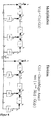
- FIG. 1 is considered, from the explanation of which then also the understanding of the circuit according to Figure 2 results by itself.
- S 2 , S 1 are switches for K signal lines with switch positions 1 and 2.
- T i One-cycle delay for K signal lines.
- the input data block [X] is contained completely or element by element in a register 12, at the output of which a value X i is present.
- the first five elements of the fail-safe data block [Y] consist of the elements of the input data block [X].
- Two parity words should now be added to the saved data block [Y].
- the individual values X i are given to the output at each division step via a switch S 1 in the "1" position, from which the error-protected data words are taken, shown here as an example as register 14.
- modulo 2 addition ( ⁇ ) by the exclusive-or elements corresponds to the following truth table (Table 3): X 1 X 2 Y 0 0 0 0 1 1 1 0 1 1 1 0
- the circuit according to FIG. 1 also contains two table memories 22 and 24, here additionally designated LUT 2 and LUT 1 , derived from the term look-up table.
- the number of memory locations in these table memories is 8 (2 K ).
- These table memories can be implemented either by commercially available electronic read-only memory modules or by programmable logic cells (PLD). Addresses A i (at the respective clock) are applied to the address inputs and, depending on the address that is created, a data word D i stored under this address is read out.
- each table memory contains for all possible values 0.1, ⁇ , ⁇ 2 .... the product result, which is obtained by multiplying the input value by the relevant coefficient of the generator polynomial. In the present case, the possible input values for the data value D 2 are multiplied by ⁇ 3 , for the data value D 1 by ⁇ .
- the ⁇ i as K-bit words can be found in the GF (2 K ) (see Table 1).
- the two switches S 1 and S 2 are initially in the "1" position.
- polynomial division steps are performed on each clock, and also the elements of [X] are given on the output for Y during the first five clocks.
- the intermediate results obtained depend on the existing data of the currently current clock and the data of the previous clock.
- the clock is generated by a clock generator in the form of a clock signal CL.
- the delay elements 18 and 20 shown in FIG. 1 each generate a delay by one clock, as can be seen from Table 2 above.
- the individual words of the input data block are transferred to the saved data block (output data block) in the first five cycles.
- the switches S 1 and S 2 are brought into the "2" position. Now the two parity words P 1 and P 2 at the output of the delay element 18 can be removed and added to the output data block.
- the switches are switched by a switch controller depending on the number of words within an input data block that is to be assumed to be known.
- Figure 2 shows a circuit for any values of 2e.
- the modulo 2 adders are bitwise shown for each of the K bits.
- the circuit can be set to one expand any number of bits, it can also be extended to any number Extend the value of 2e.
- Figure 3 shows a slightly compared to the circuit of Figure 2 modified embodiment, but on the individual representations of the individual bit lines was dispensed with.
- this circuit manages with only one switch S 1 .
- the data words are clocked into the register for the output data word Y via the two EXCLUSIVE-OR gates 17 and 16, while the switch S 1 is in the "1" position.
- the work processes in the remaining circuit correspond to the process explained above.
- the switch S 1 is set to the "2" position so that the parity words are added to the output data word Y.
- circuit shown in Figure 3 can also be carried out a modified method for the formation of parity words used as outlined below.
- FIG 4 a circuit is shown, which first determines the divisor C (z) by division and then the output polynomial Y (z) by multiplication, the division in the delay elements T 1 to T 2e and the multiplication in the Delay elements T 2e + 1 to T 4e is performed. Switch S 1 is moved from position 1 to position 2 immediately after the mth cycle at which the division has ended. Overall, m + 2e clocks are required to form the output polynomial Y (z).
- LUT Tables 4 and 5 can be used for this example.
- Switch S 1 is to be moved from position 1 to position 2 immediately after the nth cycle. To illustrate the sequence, the circuit parts are shown separately in FIG. 8.
- P (z) e.g. 2 e - X (z) - H (z)
- the circuit design of the method is shown in FIG. 6.
- the switches S 0 and S m-2e are in position 1 at the beginning of the operation.
- the multiplication of the input polynomial X (z) by the inverse polynomial H (z) according to step (1) is carried out using the tables LUT 1 to LUT m -2e and the K-fold one-stroke delay elements T 1 to T m-2e .
- step (1) is divided by the polynomial z m + 1 and the remainder is determined by switching the switches S 0 and S m-2e to position 2 immediately after the m-2 th clock.
- Division of the remainder Step (2) through the inverse polynomial H (z) takes place with the aid of the K-fold one-cycle delay elements T m-2e + 1 to T 2m-4e .
- the parity words [P] corresponding to the division words are appended directly to the information words [X].
- the advantage of the circuit is that only m-2e LUT tables be used, which is large with a number of 2e parity words compared to the number (m-2e) of information words in a block, leads to a reduction in circuitry.
- the inverse polynomial results in H (z) (z m + 1)
- G (z) z 3 + ⁇ 2 z 2 + z + ⁇ .
- the structure of the LUT tables for this example is as follows:
- the ⁇ i can be found as K-bit words from GF (2 K ).
- [X] [ ⁇ 5 ⁇ 2 ⁇ ]
- the inverse polynomial H (z) z 3 + ⁇ 2 z 2 + z + ⁇
- M 5 to M 10 represent the coefficients of the result polynomial after the multiplication step (1).
Abstract
Description
Die Erfindung betrifft ein Verfahren zum Erzeugen von fehlergesicherten Datenblöcken durch Erzeugen von Paritätsworten.The invention relates to a method for generating error-protected Blocks of data by generating parity words.
Das Erzeugen von fehlergesicherten Datenblöcken durch Erzeugen von Paritätsworten, die den einzelnen zu sichernden Informationsworten, hier als Eingangsdatenblöcke bezeichnet, hinzugefügt werden, ist auf verschiedenen Gebieten der Informationsverarbeitung bekannt. Im vorliegenden Fall geht es in erster Linie um die Fehlersicherung bei digitalen Speichersystemen.Creating fail-safe data blocks by creating Parity words, the individual information words to be secured, here referred to as input data blocks, is added on different Known areas of information processing. In the present In the first place, it is a matter of troubleshooting digital Storage systems.
Im Vordergrund steht hierbei das Compact Disc System. Ausgangspunkt
ist die Fehlersicherung von digitalen Nutzdaten [X], die zu einem Datenblock
[Y], auch Rahmen genannt, zusammengefaßt und durch Paritätsdaten
oder Paritätsworte ergänzt werden. Aus der so entstehenden Redundanz
besteht die Möglichkeit der Fehlererkennung und der Fehlerkorrektur.
Die Anzahl der korrigierbaren und erkennbaren Fehler wird
durch die sogenannte minimale Hammingdistanz dmin festgelegt, wobei
Fehler erkennbar und
Fehler korrigierbar sind. Beim Compact-Disc-System ist zum Beispiel
e=2 und k=4. In der DE 31 19 669 wird ein systematischer Code
vorgeschlagen, wobei systematisch bedeutet, daß die Eingangsinformationssymbole
unkodiert im Ausgangsblock enthalten sind. Dieser Code
basiert auf dem Galois-Feld oder Galois-Körper (GF(2K)), wobei der
Grad K die Bitanzahl der zu kodierenden Worte und die maximale
Blocklänge, d.h.: die maximale Anzahl der Worte in einem Block, zu
m=2K-1 festlegt. Bei 8-Bit-Datenworten ist zum Beispiel K=8 und die
maximale Blocklänge m = 2K-1= 255. Jedes GF(2K) wird durch ein
"primitives" Polynom Q(q) festgelegt, wobei die Elemente des GF(2K)
durch Potenzieren αi = αi = α(q) = qi ¦modQ(q) definiert sind. Die Polynome
Q(q) und die Elemente αi für jedes GF(2K) sind bekannt. Koeffizienten
von Q(q) sind Elemente aus GF(2). Q(q) ist ein irreduzibles
Polynom über GF(2), das heißt es kann nicht in ein Produkt aus Polynomen
kleineren Grades mit den Koeffizienten aus GF(2) aufgespalten
werden. Für jedes GF(2K) sind eindeutige Rechenregeln festgelegt. Man
kann die Elemente des GF(2K) tabellarisch darstellen. Zum Beispiel
ergibt sich für GF(2K) mit Q(q) = q3 + q + 1 :

Zur Erläuterung der Rechenregeln sei vorausgesetzt, daß die beiden
Elemente, oder Worte, [A] und [B] dem GF(2K) entstammen, wobei
Zur Erzeugung des Codeblocks [Y] wird gemäß der DE 31 19 669 die
Prüfmatrix in der Form

Aus dieser Operation entstehen 2e Gleichungen, aus denen die unbekannten 2e Paritätsworte [P] bestimmt werden können. In der DE'699 ist keine mögliche Schaltung zum Lösen des Gleichungssystems angegeben. Man kann nun daran denken, für jedes Paritätswort eine Reihe von Multiplikationen vorzunehmen. Das Erzeugen der Paritätsworte [P] gestaltet sich bei diesem Verfahren aufwendig und schaltungsintensiv. Die Schaltungsarchitektur ist bei hohen Datenraten und der Forderung nach Echtzeitfähigkeit sehr kostenintensiv, da sie den Gegebenheiten des Galois-Feldes und den darauf basierenden Rechenregeln angepaßt werden muß.From this operation 2e equations arise, from which the unknown 2e parity words [P] can be determined. In DE'699 is no possible circuit for solving the system of equations specified. One can now remember a number of for each parity word To make multiplications. Generation of parity words [P] This process is complex and circuit-intensive. The circuit architecture is at high data rates and demand after real-time capability very cost-intensive, since it corresponds to the circumstances of the Galois field and the calculation rules based on it got to.
Das folgende Beispiel soll die Vorgehensweise nach der oben angegebenen
Möglichkeit noch einmal verdeutlichen. In diesem Beispiel wird K
= 3, 2e = 2, m = 2K -1 = 7 und b=0 angenommen. Der Eingangs-informationsblock
sei [Y] = [X5, X4, X3, X2, X1] und der Ausgangsdatenblock
sei [Y] = [X5, X4, X3, X2, X1, P2, P1]. Für dieses Beispiel
berechnen sich aus [Y] • [H] 0 die Paritätsworte P2, P1 folgendermaßen:
Es sind nach diesem Verfahren 2e•(m-2e) = 10 Multiplikationen pro Rahmen im GF(2K) bzw. bei Einsatz tabellarischer Multiplikation, die schaltungstechnisch einfacher und schneller zu realisieren ist, 10 ROM-basierte Multiplikationstabellen zur Ermittlung von [P] erforderlich.According to this method, there are 2 ROMs (m-2e) = 10 multiplications per frame in the GF (2 K ) or when using tabular multiplication, which is easier and faster to implement in terms of circuitry, 10 ROM-based multiplication tables to determine [P] required.
Für die Anwendung im Compact-Disc-System sind beispielsweise K = 8, e = 2, m = 32 und b = 0 zu setzen. Folglich ergeben sich 2e • (m-2e) = 4 • 28 = 112 Multiplikationen pro Rahmen, was bei tabellarischer Multiplikation 112 Tabellen erfordert. Da dieser Aufwand zu groß ist, wird bei der Compact Disc auf die schnelle parallele Umsetzung verzichtet und in serieller Weise unter Einsatz eines komplexen rechnerbasierten Steuermechanismus verfahren. Die serielle Ausführung birgt allerdings den Nachteil, daß nur vergleichsweise niedrige Datenraten verarbeitet werden können.For example, for use in the compact disc system, K = 8, e = 2, m = 32 and b = 0. This results in 2e • (m-2e) = 4 • 28 = 112 multiplications per frame, which is tabular Multiplication requires 112 tables. Because this effort too is large, the compact disc is based on the fast parallel implementation dispensed and in a serial manner using a complex process computer-based control mechanism. The serial version has the disadvantage, however, that only comparatively low data rates can be processed.
Aus "Architecture for VLSI Design of Reed Solomon Encoders", Kuang J. Liu, IEEE Transactions on Computers Vol. C31, (1982) Febr., No. 2, USA, ist bekannt, mit einem Kodeerzeuger Paritätswörter für Informations-Datenblöcke mittels Polynom-Division durch das Generator-Polynom mit anschließender Restbestimmung zu erzeugen. From "Architecture for VLSI Design of Reed Solomon Encoders", Kuang J. Liu, IEEE Transactions on Computers Vol. C31, (1982) Febr., No. 2, USA, is known to use a code generator to create parity words for blocks of information using polynomial division by the generator polynomial with subsequent residual determination.
Der Erfindung liegt die Aufgabe zugrunde, eine schaltungstechnisch einfacher zu realisierende Kodierung bzw. Berechnung der Paritätsworte zu ermöglichen, wodurch sich ein geringer Aufwand bei gleichzeitig höherem Datendurchsatz einstellt.The invention has for its object a circuitry coding or calculation of the parity words easier to implement to enable, resulting in little effort at the same time sets higher data throughput.
Gelöst wird die Aufgabe durch ein Verfahren mit den Merkmalen des Anspruchs 1.The task is solved by a process with the characteristics of Claim 1.
Die Erfindung beruht auf der Ausnutzung des Umstands, daß die Blöcke
[Y] zyklisch sind. Das heißt, daß ein neuer gültiger Block [Y]i entsteht
durch zyklische Verschiebung der Elemente eines beliebigen gültigen
Blockes [Y]i:
Folglich kann die Kodeerzeugung auf einfachere Weise mittels eines
Generator-Polynoms G(z) vorgenommen werden, das auf 2e Nullstellen
aus GF(2K) basiert:
Die zyklische Eigenschaft des durch G(z) erzeugten Kodes kann unter anderem durch die Eigenschaft zm + 1 ¦mod G(z) = 0 nachgewiesen werden.The cyclic property of the code generated by G (z) can be demonstrated, among other things, by the property z m + 1 ¦ mod G (z) = 0.
Es ist üblich, den Informations-Datenblock [X] = [Xn Xn-1 ... X2 X1]
durch ein Polynom darzustellen
Es können nun die Paritätsworte Pi mittels Polynom-Division durch das
Generator-Polynom G(z) und anschließender Restbestimmung ermittelt
werden. Die Paritätsworte Pi ergeben sich dann ebenfalls in der folgenden
Polynom-Darstellung:
Diese Polynom-Division ist schaltungstechnisch verhältnismäßig einfach durchzuführen, wie in Figur 1 gezeigt ist.This polynomial division is relatively simple in terms of circuitry perform, as shown in Figure 1.
Das Verfahren soll anhand eines Beispiels erläutert werden. Für das
Beispiel sei K = 3, 2e = 2, m = 2K-1 = 7 und b = 0 angenommen.
Der zu kodierende Eingangs-Informationsblock sei [X] = [α2 0 α5 0 α].
Das zugehörige Informations-Polynom ist dann X(z) = α2z4 + α5z2 +
α. Als Generator-Polynom ergibt sich
Die Ermittlung der Paritätsworte durch Polynom-Division und Restbestimmung
liefert dann
Folglich ergeben sich die gesuchten Paritätsworte als Koeffizienten von
P(z) zu P2 = α6, P1 = α 2 und der gesuchte Ausgangsblock ist dann
Die Lösung des aus der Prüfmatrix [H] entstehenden Gleichungssystems
(1) und (2) führt zu dem gleichen Ergebnis, allerdings nach einem
anderen, schaltungsmäßig aufwendigeren Verfahren:
Bei einem sogenannten verkürzten Kode, wie er bei der Compact Disc Verwendung findet, wird nicht die maximal mögliche Anzahl m = 2K-1, sondern eine geringere Anzahl mv zu einem Block zusammengefaßt. Daß das erfindungsgemäße Verfahren auch auf verkürzte Kodes anzuwenden ist, soll das nachfolgende Beispiel zeigen. Hier wird K = 3, 2e = 2, m(max) = 2K-1=7, m, (verkürzt) = 5 und b = 0 gewählt.With a so-called shortened code, as used in the compact disc, the maximum possible number m = 2 K -1, but a smaller number m v is combined to form a block. The following example shows that the method according to the invention can also be applied to shortened codes. Here K = 3, 2e = 2, m (max) = 2 K -1 = 7, m, (shortened) = 5 and b = 0 is selected.
Als Eingangs-Informationsdatenblock sei
Das zu [X] gehörende Informations-Polynom lautet dann
Wird wieder das Generator-Polynom
Das obige Gleichungssystem (1), (2) liefert:
Um die einzelnen Schritte bei der schaltungstechnisch durchgeführten
Polynom-Division zu verdeutlichen, soll das oben angegebene Beispiel
des Paritätspolynoms gemäß Gleichung (3) im einzelnen ausgeführt
werden:

Wie bereits erwähnt, ist zur Erzeugung der Paritätsworte hier lediglich der Polynomrest von Interesse, das Ergebnis der Division, also der rechts oben stehende Quotient ist nur insofern wichtig, als die einzelnen Koeffizienten α2, α5, ... für die Multiplikation mit den einzelnen Termen des Generatorpolynoms verwendet werden. Man erkennt, daß das bei der Multiplikation des jeweiligen Zwischenergebnisses mit den einzelnen Termen des Generatorpolynoms gewonnene Ergebnis nicht berücksichtigt zu werden braucht, da es bei der nachfolgenden im GF(2K) definierten Addition (entspricht der Subtraktion) wegfällt.As already mentioned, only the polynomial residue is of interest for generating the parity words, the result of the division, i.e. the quotient at the top right, is only important insofar as the individual coefficients α 2 , α 5 , ... are used for multiplication by individual terms of the generator polynomial can be used. It can be seen that the result obtained by multiplying the respective intermediate result by the individual terms of the generator polynomial need not be taken into account, since it does not apply to the subsequent addition (corresponding to the subtraction) defined in the GF (2 K ).
Für das hier betrachtete Beispiel sind also lediglich der Term α3z und α
des Generatorpolynoms wichtig.
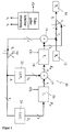
Zunächst sei Figur 1 betrachtet, aus deren Erläuterung sich dann auch das Verständnis der Schaltung nach Figur 2 von allein ergibt.First of all, FIG. 1 is considered, from the explanation of which then also the understanding of the circuit according to Figure 2 results by itself.
Die schaltungstechnische Realisierung der Polynom-Division gemäß der Rechenregeln im GF(2K) soll anhand von Figur 1, in der alle Signalverbindungen aus Bündeln von K-Leitungen bestehen, erläutert werden. The circuitry implementation of the polynomial division according to the calculation rules in GF (2 K ) will be explained with reference to FIG. 1, in which all signal connections consist of bundles of K lines.
S2, S1 sind Schalter für K-Signalleitungen mit den Schalterstellungen 1 und 2.S 2 , S 1 are switches for K signal lines with switch positions 1 and 2.
Ti: Ein-Takt-Verzögerung für K Signalleitungen.T i : One-cycle delay for K signal lines.
Der Eingangsdatenblock [X] sei vollständig oder elementenweise in einem Register 12 enthalten, an dessen Ausgang jeweils ein Wert Xi ansteht.The input data block [X] is contained completely or element by element in a register 12, at the output of which a value X i is present.
Da bei dem hier betrachteten Beispiel K=3, sind sämtliche Signalleitungen dreiadrig ausgeführt, eine Ader für jeweils ein Bit. Entsprechendes gilt auch für die übrigen Elemente der in Figur 1 gezeigten Schaltung.Since K = 3 in the example considered here, all signal lines are three-wire, one wire for each bit. Corresponding also applies to the other elements of the circuit shown in FIG. 1.
Wie oben gezeigt, bestehen die fünf ersten Elemente des fehlergesicherten Datenblocks [Y] aus den Elementen des Eingangsdatenblocks [X]. Dem gesicherten Datenblock [Y] sollen jetzt zwei Paritätswörter hinzugefügt werden. Während der schrittweise vorgenommenen Polynomdivision zur Erzeugung der Paritätswörter werden bei jedem Divisionsschritt die einzelnen Werte Xi über einen in der Stellung "1" befindlichen Schalter S1 auf den Ausgang gegeben, von dem die fehlergesicherten Datenwörter abgenommen werden, hier dargestellt beispielhaft als Register 14.As shown above, the first five elements of the fail-safe data block [Y] consist of the elements of the input data block [X]. Two parity words should now be added to the saved data block [Y]. During the step-by-step polynomial division to generate the parity words, the individual values X i are given to the output at each division step via a switch S 1 in the "1" position, from which the error-protected data words are taken, shown here as an example as register 14.
Die Schaltung nach Figur 1 enthält Verzögerungsglieder 18 und 20, hier
zusätzlich mit T2 bzw. T1 bezeichnet, entsprechend 2e=2. Für die Verzögerungsglieder
können bekannte digitale D-Flipflops mit Taktsteuerung
verwendet werden, die zum Beispiel die Zustandsfolgetabelle Q+=f (Cl,
D)
An den Ausgängen der beiden Verzögerungsglieder 18 und 20 befindet sich jeweils ein Element für die Modulo 2-Addition in Form eines Exklusiv-Oder-Glieds 16 bzw. 17 (es sei noch einmal angemerkt, daß entsprechend K=3 das Exklusiv-Oder-Glied 16 ebenso wie das Glied 17 tatsächlich aus drei Elementen gebildet ist).Located at the outputs of the two delay elements 18 and 20 one element for modulo 2 addition in the form of a Exclusive OR elements 16 and 17 (it should be noted once again that corresponding to K = 3, the exclusive-or link 16 as well as the link 17 is actually made up of three elements).
Die Modulo 2-Addition (⊕) durch die Exklusiv-Oder-Glieder entspricht
folgender Wahrheitstabelle (Tabelle 3):
Die Schaltung nach Figur 1 enthält außerdem zwei Tabellenspeicher 22 und 24, hier zusätzlich bezeichnet mit LUT2 bzw. LUT1, abgeleitet von dem Begriff Look-Up-Table. Die Anzahl der Speicherplätze in diesen Tabellenspeichern beträgt 8 (2K). Diese Tabellenspeicher können entweder durch handelsübliche elektronische Read-Only-Memory-Bausteine oder durch programmierbare Logikzellen (PLD) realisiert werden. An die Adresseneingänge werden Adressen Ai (bei dem jeweiligen Takt) gelegt, und abhängig von der angelegten Adresse wird ein unter dieser Adresse gespeichertes Datenwort Di ausgelesen. Betrachtet man die Polynom-Division, so enthält jeder Tabellenspeicher für alle in Frage kommenden Werte 0,1, α, α2 .... das Produktergebnis, welches durch Multiplizieren des Eingangswerts mit dem betreffenden Koeffizienten des Generator-Polynoms entsteht. Im vorliegenden Fall werden also die möglichen Eingangswerte für den Datenwert D2 mit α3 multipliziert, für den Datenwert D1 mit α.The circuit according to FIG. 1 also contains two table memories 22 and 24, here additionally designated LUT 2 and LUT 1 , derived from the term look-up table. The number of memory locations in these table memories is 8 (2 K ). These table memories can be implemented either by commercially available electronic read-only memory modules or by programmable logic cells (PLD). Addresses A i (at the respective clock) are applied to the address inputs and, depending on the address that is created, a data word D i stored under this address is read out. Looking at the polynomial division, each table memory contains for all possible values 0.1, α, α 2 .... the product result, which is obtained by multiplying the input value by the relevant coefficient of the generator polynomial. In the present case, the possible input values for the data value D 2 are multiplied by α 3 , for the data value D 1 by α.
Allgemein gesprochen:Generally speaking:
Die LUT1 stellen die Multiplikation der höchsten Stelle des bei der Polynom-Division
entstehenden Zwischenergebnisse mit den jeweiligen
Koeffizienten des Generator-Polynoms
Die LUTi sind gemäß folgender Gleichung zu programmieren
Für das vorliegende Beispiel (G(z) = z2 + α3z + α) sind die Tabellenspeicher
mit folgendem Inhalt programmiert:
Zur Aufstellung der LUT-Tabellen sind die αi als K-Bit-Worte aus dem GF(2K) (s. Tabelle 1) zu entnehmen.To compile the LUT tables, the α i as K-bit words can be found in the GF (2 K ) (see Table 1).
Der Ablauf der Polynom-Division und die Restermittlung mit Hilfe der in Figur 1 gezeigten Schaltung läuft folgendermaßen ab, wobei noch einmal daran erinnert sei, daß im vorliegenden Beispiel der Eingangsdatenblock (X) = [α20 α50 α] ist.The sequence of the polynomial division and the residual determination using the circuit shown in FIG. 1 proceed as follows, it being recalled that in the present example the input data block (X) = [α 2 0 α 5 0 α].
Wie bereits erwähnt, sind die beiden Schalter S1 und S2 zunächst in der
Stellung "1". Wie ebenfalls schon erwähnt, werden bei jedem Takt
Schritte der Polynom-Division durchgeführt, und außerdem werden
während der ersten fünf Takte die Elemente von [X] auf den Ausgang
für Y gegeben. Im vorliegenden Fall umfaßt der Eingangsdatenblock
n=5 Informationsworte mit jeweils k=3 Bits. Wie aus der nachstehenden
Tabelle 6 ersichtlich ist, hängen die erhaltenen Zwischenergebnisse
von den vorhandenen Daten des gerade aktuellen Takts und den Daten
des vorausgehenden Takts ab. Der Takt wird durch einen Taktgeber in
Form eines Taktsignals CL erzeugt. Die in Figur 1 gezeigten Verzögerungsglieder
18 und 20 erzeugen jeweils eine Verzögerung um einen
Takt, wie aus der obigen Tabelle 2 ersichtlich ist.
Bei der Aufstellung der Zustandstabelle sind die nachfolgenden Zustandsgleichungen
hilfreich:
Die geklammerten Ausdrücke in Tabelle 6 geben die Positionen im Datenrahmen Y an, während sich j auf den Takt bezieht. (Dies gilt auch für die weiteren Tabellen unten.)The bracketed expressions in Table 6 indicate the positions in the Data frame Y on, while j refers to the clock. (This is also valid for the other tables below.)
Wie aus der obigen Tabelle ersichtlich ist, werden in den ersten fünf Takten die einzelnen Worte des Eingangsdatenblocks in den gesicherten Datenblock (Ausgangsdatenblock) übernommen. Vor dem Takt n+1 werden die Schalter S1 und S2 in die Stellung "2" gebracht. Nun können die zwei Paritätsworte P1 und P2 am Ausgang des Verzögerungsglieds 18 abgenommen und an den Ausgangsdatenblock angefügt werden. Nach dem Takt m=7 ist die Bildung des gesicherten Datenblocks [Y] beendet, und die Schaltung ist für die Bildung der Paritätswörter für den nächsten Eingangsdatenblock bereit, nachdem die Schalter S1 und S2 wieder in die Stellung "1" gebracht worden sind. Das Umschalten der Schalter erfolgt durch eine Schaltersteuerung in Abhängigkeit der als bekannt vorauszusetzenden Anzahl von Worten innerhalb eines Eingangsdatenblocks.As can be seen from the table above, the individual words of the input data block are transferred to the saved data block (output data block) in the first five cycles. Before the cycle n + 1, the switches S 1 and S 2 are brought into the "2" position. Now the two parity words P 1 and P 2 at the output of the delay element 18 can be removed and added to the output data block. After the clock m = 7, the formation of the secured data block [Y] has ended and the circuit is ready for the formation of the parity words for the next input data block after the switches S 1 and S 2 have been returned to the "1" position . The switches are switched by a switch controller depending on the number of words within an input data block that is to be assumed to be known.
Mit Hilfe der beiden Formeln unter der Tabelle 6 ergibt sich zum Beispiel
für Z25:
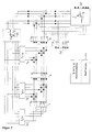
Figur 2 zeigt eine Schaltung für beliebige Werte von 2e. Zusätzlich zu den Einzelheiten aus Figur 1 sind für die Verzögerungsglieder noch die einzelnen bitweisen Elemente jedes Verzögerungsglieds sowie der zugehörige Takteingang dargestellt. Die Modulo 2-Addierer sind bitweise für jedes einzelne der K-Bits dargestellt. Die Schaltung läßt sich auf eine beliebige Anzahl von Bits erweitern, ebenso läßt sie sich auf einen beliebigen Wert von 2e erweitern.Figure 2 shows a circuit for any values of 2e. In addition to the details of Figure 1 are still for the delay elements individual bitwise elements of each delay element and the associated one Clock input shown. The modulo 2 adders are bitwise shown for each of the K bits. The circuit can be set to one expand any number of bits, it can also be extended to any number Extend the value of 2e.
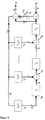
Figur 3 zeigt eine gegenüber der Schaltung nach Figur 2 geringfügig abgewandelte Ausführungsform, wobei jedoch auf die Einzeldarstellungen der einzelnen Bitleitungen verzichtet wurde.Figure 3 shows a slightly compared to the circuit of Figure 2 modified embodiment, but on the individual representations of the individual bit lines was dispensed with.
Wie links in Figur 3 zu erkennen ist, kommt diese Schaltung mit nur einem Schalter S1 aus. Zunächst werden die Datenwörter über die beiden EXKLUSIV-ODER-Gatter 17 und 16 in das Register für das Ausgangsdatenwort Y eingetaktet, während der Schalter S1 in der Stellung "1" steht. Die Arbeitsabläufe in der übrigen Schaltung entsprechen dem oben erläuterten Ablauf. Nach Ende des Datenworts wird der Schalter S1 in die Stellung "2" gebracht, so daß die Paritätswörter an das Ausgangsdatenwort Y angefügt werden. As can be seen on the left in FIG. 3, this circuit manages with only one switch S 1 . First of all, the data words are clocked into the register for the output data word Y via the two EXCLUSIVE-OR gates 17 and 16, while the switch S 1 is in the "1" position. The work processes in the remaining circuit correspond to the process explained above. At the end of the data word, the switch S 1 is set to the "2" position so that the parity words are added to the output data word Y.
Die in Figur 3 gezeigte Schaltung kann aber auch zum Durchführen eines abgewandelten Verfahrens zur Bildung von Paritätswörtern verwendet werden, wie unten ausgeführt wird.The circuit shown in Figure 3 can also be carried out a modified method for the formation of parity words used as outlined below.
Eine weitere Möglichkeit der Paritätsbildung besteht darin, nicht wie in
der Schaltung nach Figur 1 durchgeführt, den Rest aus der Division des
verschobenen Eingangs-Polynoms zm-n X(z) durch das Generator-Polynom
G(z) gemäß
Das Schaltungsbeispiel in Figur 5 zeigt den Aufbau für den Fall, daß
2e=2 Paritätsworte für einen Informationsblock aus K = 3 Bit-Worten
unter Verwendung des Generatorpolynoms G(z) = z2 + α3z + α ermittelt
werden. Für dieses Beispiel können die LUT-Tabellen 4 und 5
verwendet werden. Für den Eingangs-Informationsblock [X] = [α20 α50
a] und das Generatorpolynom G(z) = z2 + α3z + α ergibt sich beispielsweise
die folgende taktabhängige Zustandstabelle der Kodierschritte:
Bei der Aufstellung der Zustandstabelle ist es der Übersichtlichkeit
halber sinnvoll, die nachfolgenden Zustandsgleichungen zu verwenden:
Figur 3 zeigt die schaltungstechnische Ausführung des kombinierten
Divisions-Multiplikationsverfahrens, das die Operationen
Zur Ermittlung der 2e Paritätsworte sind bei Verwendung des Generator-polynoms
G(z) insgesamt 2e LUT-Tabellen erforderlich. Falls demnach
in einem Ausgangsdatenblock [Y] die Anzahl 2e der Paritätsworte [P]
größer ist als die Anzahl der Informationsworte, so ist es zur Einsparung
von LUT-Tabellen günstiger, die Berechnung der Paritätsworte mit Hilfe
eines inversen Polynoms H(z) durchzuführen. Zwischen dem inversen
Polynom H(z) und dem Generatorpolynom G(z) besteht der folgende
Zusammenhang:
Da das dem Ausgangsdatenblock [Y] zugeordnete Ausgangspolynom
Y(z) aus dem Informationspolynom X(z) und dem Paritätspolynom P(z)
besteht, ergibt sich:
Aus der Bedingung
Folglich ist dann
Die Umstellung nach P(z) liefert:
Für die Ermittlung der Paritätsworte ergeben sich demnach die folgenden
Verfahrensschritte:
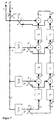
Die schaltungstechnische Ausführung des Verfahrens ist in Figur 6
dargestellt. Die LUT1 stellen die Multiplikation der höchsten Stelle des
bei der Polynom-Division bzw. Polynom-Multiplikation entstehenden
Zwischenergebnisses mit den jeweiligen Koeffizienten des inversen
Polynoms
Die LUTi sind gemäß folgender Gleichung zu programmieren:
Der Vorteil der Schaltung liegt darin, daß nur m-2e LUT-Tabellen verwendet werden, was bei einer Anzahl von 2e Paritätsworten, die groß gegenüber der Anzahl (m-2e) der Informationsworte in einem Block ist, zur Reduzierung des Schaltungsaufwandes führt.The advantage of the circuit is that only m-2e LUT tables be used, which is large with a number of 2e parity words compared to the number (m-2e) of information words in a block, leads to a reduction in circuitry.
Das Schaltungsbeispiel in Figur 7 zeigt den Aufbau für den Fall, daß
2e=4 Paritätsworte für einen Informationsblock aus K = 3 Bit-Worten
ermittelt werden sollen. Der Ausgangsblock hat die Form:
Als Generatorpolynoms wird G(z) = z4 + α2z3 + α5z2 + α5z + α6
zugrunde gelegt. Folglich ergibt sich das inverse Polynom zu H(z) =
(zm + 1) G(z) = z3 + α2z2 + z + α. Der Aufbau der LUT-Tabellen
ist für dieses Beispiel folgendermaßen durchzuführen:

Zur Aufstellung der LUT-Tabellen sind die αi als K-Bit-Worte aus
GF(2K) zu entnehmen. Für den Eingangs-Informationsblock [X] = [α5 α2
α] und das inverse Polynom H(z) = z3 + α2z2 + z + α ergibt sich
beispielsweise die folgende taktabhängige Zustandstabelle der Kodierschritte:
M5 bis M10 stellen die Koeffizienten des Ergebnis-Polynoms nach dem
Multiplikationsschritt (1) dar. Bei der Aufstellung der Zustandstabelle ist
es der Übersichtlichkeit halber sinnvoll, die nachfolgenden Zustandsgleichungen
zu verwenden:
Claims (3)
- A method for generating error-protected data blocks by generating 2e parity words per input data block [X], where e is the number of errors to be corrected per block, for a shortened or unshortened, systematic, cyclic and 2 K -valued block code whose elements are from GF(2 K ) and whose generating polynomial G(z) fulfills 2e zeros in GF(2 K ), characterized by the following steps:a) forming the generating polynomial G(z);b) forming an inverse polynomial H(z) by dividing the polynomial zm + 1 by the generating polynomial G(z),c) extending the block by shifting the input block [X] = [Xi , Xi -1, ... X 2 X 1] by 2e word places to make room for the 2e parity words [P 2 e P 2 e -1 ... P 2 P 1] so that the output block has the form [Y] = [Xi, Xi -1, ... X 2 X 1 P 2e P 2e-1 ... P 2 P 1];d) multiplying the shifted input polynomial X(z) associated with the input block [X] by the inverse polynomial H(z) according to the computing rules in GF(2 K ),e) dividing the result from step d) by the polynomial zm + 1 according to the computing rules in GF(2 K ) and determining the remainder from said division,f) dividing the remainder from step e) by the inverse polynomial H(z) and determining the divisor words [C 2e C 2e-1 ... C 2 C 1] according to the computing rules in GF(2 K ), andg) obtaining the parity words [P] = [P 2e P 2e-1 ... P 2 P 1] from the divisor words obtained from step f) by the identity [P] = C 2e C 2e-1 ... C 2 C 1].
- The method of claim 1, characterized in that the generating polynomial is formed by multiplying as defined in GF(2 K ) altogether 2e different terms, each term arising from adding as defined in GF(2 K ) the shift operator z and one of the possible nonzero elements of GF(2 K ).
- The method of claim 2, characterized in that the number i of words in an input block [X] = [XiXi -1 ... X 2 X 1] is either i = 24 or i = 28, the number 2e of parity words [P 2 e P 2 e- 1 ... P 2 P 1] is 2e = 4, the generating polynomial G(z) = (z+α0) (z+α1)(z+α2)(z+α3) = z4 + α 75 z 3 + α 249 z 2 + α 78 z + α 6, and the Galois field underlying the operations and elements is GF(2 K ) with K=8, where αj is a root of the generating polynomial.
Priority Applications (5)
| Application Number | Priority Date | Filing Date | Title |
|---|---|---|---|
| DE59800859T DE59800859D1 (en) | 1998-10-20 | 1998-10-20 | Method and arrangement for generating error-protected data blocks by generating parity words and data carriers with data blocks generated according to the method |
| EP98119880A EP0996231B1 (en) | 1998-10-20 | 1998-10-20 | Method and device for generating error protected data blocks by generating parity words as well as data carrier including data blocks generated according to the method |
| AT98119880T ATE202244T1 (en) | 1998-10-20 | 1998-10-20 | METHOD AND ARRANGEMENT FOR GENERATING ERROR-PROOF DATA BLOCKS BY GENERATING PARITY WORDS AND DATA CARRIERS WITH DATA BLOCKS GENERATED ACCORDING TO THE METHOD |
| PCT/EP1999/007570 WO2000024130A1 (en) | 1998-10-20 | 1999-10-08 | Method and device for producing data blocks which are error-protected through production of parity words, and data medium comprising data blocks produced according to said method |
| AU63367/99A AU6336799A (en) | 1998-10-20 | 1999-10-08 | Method and device for producing data blocks which are error-protected through production of parity words, and data medium comprising data blocks produced according to said method |
Applications Claiming Priority (1)
| Application Number | Priority Date | Filing Date | Title |
|---|---|---|---|
| EP98119880A EP0996231B1 (en) | 1998-10-20 | 1998-10-20 | Method and device for generating error protected data blocks by generating parity words as well as data carrier including data blocks generated according to the method |
Publications (2)
| Publication Number | Publication Date |
|---|---|
| EP0996231A1 EP0996231A1 (en) | 2000-04-26 |
| EP0996231B1 true EP0996231B1 (en) | 2001-06-13 |
Family
ID=8232827
Family Applications (1)
| Application Number | Title | Priority Date | Filing Date |
|---|---|---|---|
| EP98119880A Expired - Lifetime EP0996231B1 (en) | 1998-10-20 | 1998-10-20 | Method and device for generating error protected data blocks by generating parity words as well as data carrier including data blocks generated according to the method |
Country Status (5)
| Country | Link |
|---|---|
| EP (1) | EP0996231B1 (en) |
| AT (1) | ATE202244T1 (en) |
| AU (1) | AU6336799A (en) |
| DE (1) | DE59800859D1 (en) |
| WO (1) | WO2000024130A1 (en) |
Family Cites Families (6)
| Publication number | Priority date | Publication date | Assignee | Title |
|---|---|---|---|---|
| JPS574629A (en) * | 1980-05-21 | 1982-01-11 | Sony Corp | Data transmitting method capable of correction of error |
| JPS62180617A (en) * | 1986-02-04 | 1987-08-07 | Victor Co Of Japan Ltd | Parity generation circuit |
| US5040179A (en) * | 1989-08-18 | 1991-08-13 | Loral Aerospace Corp. | High data rate BCH encoder |
| US5140596A (en) * | 1990-02-20 | 1992-08-18 | Eastman Kodak Company | High speed encoder for non-systematic codes |
| US5285455A (en) * | 1992-02-03 | 1994-02-08 | Lsi Logic Corporation | Serial data encoder |
| EP0584864B1 (en) * | 1992-08-21 | 1997-11-05 | Koninklijke Philips Electronics N.V. | A hardware-efficient method and device for encoding BCH codes and in particular Reed-Solomon codes |
-
1998
- 1998-10-20 DE DE59800859T patent/DE59800859D1/en not_active Expired - Fee Related
- 1998-10-20 AT AT98119880T patent/ATE202244T1/en not_active IP Right Cessation
- 1998-10-20 EP EP98119880A patent/EP0996231B1/en not_active Expired - Lifetime
-
1999
- 1999-10-08 AU AU63367/99A patent/AU6336799A/en not_active Abandoned
- 1999-10-08 WO PCT/EP1999/007570 patent/WO2000024130A1/en active Search and Examination
Also Published As
| Publication number | Publication date |
|---|---|
| EP0996231A1 (en) | 2000-04-26 |
| ATE202244T1 (en) | 2001-06-15 |
| DE59800859D1 (en) | 2001-07-19 |
| AU6336799A (en) | 2000-05-08 |
| WO2000024130A1 (en) | 2000-04-27 |
Similar Documents
| Publication | Publication Date | Title |
|---|---|---|
| DE2916710C2 (en) | ||
| DE69834542T2 (en) | HARDWARE OPTIMIZED REED SOLOMON DECODER FOR DECODING LARGE DATA BLOCKS | |
| DE2106314B2 (en) | Arrangement for error detection and correction in a byte consisting of b bits of a data block containing K data bytes | |
| DE2159108A1 (en) | Arrangement for generating cyclic redundancy check characters | |
| DE2834963A1 (en) | PROCEDURE AND EQUIPMENT FOR ERROR CORRECTION OF TRANSMITTED DATA | |
| DE69907566T2 (en) | Reed Solomon coding device and Reed Solomon coding method | |
| EP0545498B1 (en) | Method and circuit for decoding RS-coded data signals | |
| DE2262070A1 (en) | ERROR CORRECTION SYSTEM WORKING WITH SLIDING REGISTERS | |
| DE102012208711B4 (en) | Device for generating a checksum | |
| DE4220196C2 (en) | Semiconductor memory device and method for correcting a data error in a semiconductor memory device according to a predetermined Hamming matrix | |
| DE4229666A1 (en) | ALTERNATIVE WORKING DIVISION | |
| DE102011085602A1 (en) | Apparatus and method for correcting at least one bit error in a coded bit sequence | |
| DE69732076T2 (en) | Reed-Solomon decoder with universal processor unit and special circuits | |
| DE4105860C2 (en) | Circuit arrangement for recognizing and correcting errors in data words | |
| DE2217935A1 (en) | Arrangement and procedure for correcting double errors | |
| DE3404417A1 (en) | CODER TEST CIRCUIT ARRANGEMENT | |
| DE102006005817A1 (en) | Error detection device for e.g. address decoder, has comparing unit to output signal based on comparison of input and regenerated addresses, where signal displays error during conversion, when input and regenerated addresses do not coincide | |
| DE69837784T2 (en) | IMPROVED FIVE-ERROR CORRECTION SYSTEM | |
| DE102020110787B3 (en) | CIRCUIT AND PROCEDURE FOR ENCODING OR DECODING A DATA WORD | |
| DE3752367T2 (en) | Error correction unit | |
| DE4117726C2 (en) | Error correction procedure and device for its implementation | |
| DE3702697C2 (en) | ||
| EP0996231B1 (en) | Method and device for generating error protected data blocks by generating parity words as well as data carrier including data blocks generated according to the method | |
| DE102016104012A1 (en) | Processing a data word | |
| DE102013201422B3 (en) | Method for restoring lost and/or damaged data transmitted from transmitting device to receiving device, involves replacing current entry of LDPC parity check matrix with entry of Galois field until entry in matrix is modified |
Legal Events
| Date | Code | Title | Description |
|---|---|---|---|
| PUAI | Public reference made under article 153(3) epc to a published international application that has entered the european phase |
Free format text: ORIGINAL CODE: 0009012 |
|
| 17P | Request for examination filed |
Effective date: 19981020 |
|
| AK | Designated contracting states |
Kind code of ref document: A1 Designated state(s): AT BE CH CY DE DK ES FI FR GB GR IE IT LI LU MC NL PT SE |
|
| AX | Request for extension of the european patent |
Free format text: AL;LT;LV;MK;RO;SI |
|
| GRAG | Despatch of communication of intention to grant |
Free format text: ORIGINAL CODE: EPIDOS AGRA |
|
| GRAG | Despatch of communication of intention to grant |
Free format text: ORIGINAL CODE: EPIDOS AGRA |
|
| GRAH | Despatch of communication of intention to grant a patent |
Free format text: ORIGINAL CODE: EPIDOS IGRA |
|
| AKX | Designation fees paid |
Free format text: AT BE CH CY DE DK ES FI FR GB GR IE IT LI LU MC NL PT SE |
|
| AXX | Extension fees paid |
Free format text: AL PAYMENT 20001010;LT PAYMENT 20001010;LV PAYMENT 20001010;MK PAYMENT 20001010;RO PAYMENT 20001010;SI PAYMENT 20001010 |
|
| GRAH | Despatch of communication of intention to grant a patent |
Free format text: ORIGINAL CODE: EPIDOS IGRA |
|
| GRAA | (expected) grant |
Free format text: ORIGINAL CODE: 0009210 |
|
| AK | Designated contracting states |
Kind code of ref document: B1 Designated state(s): AT BE CH CY DE DK ES FI FR GB GR IE IT LI LU MC NL PT SE |
|
| AX | Request for extension of the european patent |
Free format text: AL PAYMENT 20001010;LT PAYMENT 20001010;LV PAYMENT 20001010;MK PAYMENT 20001010;RO PAYMENT 20001010;SI PAYMENT 20001010 |
|
| LTIE | Lt: invalidation of european patent or patent extension | ||
| PG25 | Lapsed in a contracting state [announced via postgrant information from national office to epo] |
Ref country code: NL Free format text: LAPSE BECAUSE OF FAILURE TO SUBMIT A TRANSLATION OF THE DESCRIPTION OR TO PAY THE FEE WITHIN THE PRESCRIBED TIME-LIMIT Effective date: 20010613 Ref country code: IT Free format text: LAPSE BECAUSE OF FAILURE TO SUBMIT A TRANSLATION OF THE DESCRIPTION OR TO PAY THE FEE WITHIN THE PRESCRIBED TIME-LIMIT;WARNING: LAPSES OF ITALIAN PATENTS WITH EFFECTIVE DATE BEFORE 2007 MAY HAVE OCCURRED AT ANY TIME BEFORE 2007. THE CORRECT EFFECTIVE DATE MAY BE DIFFERENT FROM THE ONE RECORDED. Effective date: 20010613 Ref country code: IE Free format text: LAPSE BECAUSE OF FAILURE TO SUBMIT A TRANSLATION OF THE DESCRIPTION OR TO PAY THE FEE WITHIN THE PRESCRIBED TIME-LIMIT Effective date: 20010613 Ref country code: GB Free format text: LAPSE BECAUSE OF FAILURE TO SUBMIT A TRANSLATION OF THE DESCRIPTION OR TO PAY THE FEE WITHIN THE PRESCRIBED TIME-LIMIT Effective date: 20010613 Ref country code: FR Free format text: LAPSE BECAUSE OF FAILURE TO SUBMIT A TRANSLATION OF THE DESCRIPTION OR TO PAY THE FEE WITHIN THE PRESCRIBED TIME-LIMIT Effective date: 20010613 Ref country code: FI Free format text: LAPSE BECAUSE OF FAILURE TO SUBMIT A TRANSLATION OF THE DESCRIPTION OR TO PAY THE FEE WITHIN THE PRESCRIBED TIME-LIMIT Effective date: 20010613 Ref country code: CY Free format text: LAPSE BECAUSE OF NON-PAYMENT OF DUE FEES Effective date: 20010613 |
|
| REF | Corresponds to: |
Ref document number: 202244 Country of ref document: AT Date of ref document: 20010615 Kind code of ref document: T |
|
| REF | Corresponds to: |
Ref document number: 59800859 Country of ref document: DE Date of ref document: 20010719 |
|
| REG | Reference to a national code |
Ref country code: IE Ref legal event code: FG4D Free format text: GERMAN |
|
| PG25 | Lapsed in a contracting state [announced via postgrant information from national office to epo] |
Ref country code: SE Free format text: LAPSE BECAUSE OF FAILURE TO SUBMIT A TRANSLATION OF THE DESCRIPTION OR TO PAY THE FEE WITHIN THE PRESCRIBED TIME-LIMIT Effective date: 20010913 Ref country code: DK Free format text: LAPSE BECAUSE OF FAILURE TO SUBMIT A TRANSLATION OF THE DESCRIPTION OR TO PAY THE FEE WITHIN THE PRESCRIBED TIME-LIMIT Effective date: 20010913 |
|
| PG25 | Lapsed in a contracting state [announced via postgrant information from national office to epo] |
Ref country code: GR Free format text: LAPSE BECAUSE OF FAILURE TO SUBMIT A TRANSLATION OF THE DESCRIPTION OR TO PAY THE FEE WITHIN THE PRESCRIBED TIME-LIMIT Effective date: 20010914 |
|
| PG25 | Lapsed in a contracting state [announced via postgrant information from national office to epo] |
Ref country code: PT Free format text: LAPSE BECAUSE OF FAILURE TO SUBMIT A TRANSLATION OF THE DESCRIPTION OR TO PAY THE FEE WITHIN THE PRESCRIBED TIME-LIMIT Effective date: 20010917 |
|
| PG25 | Lapsed in a contracting state [announced via postgrant information from national office to epo] |
Ref country code: MC Free format text: LAPSE BECAUSE OF NON-PAYMENT OF DUE FEES Effective date: 20011020 Ref country code: LU Free format text: LAPSE BECAUSE OF NON-PAYMENT OF DUE FEES Effective date: 20011020 Ref country code: AT Free format text: LAPSE BECAUSE OF NON-PAYMENT OF DUE FEES Effective date: 20011020 |
|
| PG25 | Lapsed in a contracting state [announced via postgrant information from national office to epo] |
Ref country code: BE Free format text: LAPSE BECAUSE OF NON-PAYMENT OF DUE FEES Effective date: 20011031 |
|
| NLV1 | Nl: lapsed or annulled due to failure to fulfill the requirements of art. 29p and 29m of the patents act | ||
| GBV | Gb: ep patent (uk) treated as always having been void in accordance with gb section 77(7)/1977 [no translation filed] |
Effective date: 20010613 |
|
| PG25 | Lapsed in a contracting state [announced via postgrant information from national office to epo] |
Ref country code: ES Free format text: LAPSE BECAUSE OF FAILURE TO SUBMIT A TRANSLATION OF THE DESCRIPTION OR TO PAY THE FEE WITHIN THE PRESCRIBED TIME-LIMIT Effective date: 20011220 |
|
| EN | Fr: translation not filed | ||
| PLBE | No opposition filed within time limit |
Free format text: ORIGINAL CODE: 0009261 |
|
| STAA | Information on the status of an ep patent application or granted ep patent |
Free format text: STATUS: NO OPPOSITION FILED WITHIN TIME LIMIT |
|
| BERE | Be: lapsed |
Owner name: DIG MICROCODE G.M.B.H. Effective date: 20011031 |
|
| 26N | No opposition filed | ||
| PG25 | Lapsed in a contracting state [announced via postgrant information from national office to epo] |
Ref country code: DE Free format text: LAPSE BECAUSE OF NON-PAYMENT OF DUE FEES Effective date: 20020702 |
|
| PG25 | Lapsed in a contracting state [announced via postgrant information from national office to epo] |
Ref country code: LI Free format text: LAPSE BECAUSE OF NON-PAYMENT OF DUE FEES Effective date: 20021031 Ref country code: CH Free format text: LAPSE BECAUSE OF NON-PAYMENT OF DUE FEES Effective date: 20021031 |
|
| REG | Reference to a national code |
Ref country code: CH Ref legal event code: PL |