EP0994258B1 - Scroll fluid machine - Google Patents
Scroll fluid machine Download PDFInfo
- Publication number
- EP0994258B1 EP0994258B1 EP99120545A EP99120545A EP0994258B1 EP 0994258 B1 EP0994258 B1 EP 0994258B1 EP 99120545 A EP99120545 A EP 99120545A EP 99120545 A EP99120545 A EP 99120545A EP 0994258 B1 EP0994258 B1 EP 0994258B1
- Authority
- EP
- European Patent Office
- Prior art keywords
- scroll
- cooling
- motor
- disk
- cooling gas
- Prior art date
- Legal status (The legal status is an assumption and is not a legal conclusion. Google has not performed a legal analysis and makes no representation as to the accuracy of the status listed.)
- Expired - Lifetime
Links
- 239000012530 fluid Substances 0.000 title claims description 25
- 238000001816 cooling Methods 0.000 claims description 53
- 239000000112 cooling gas Substances 0.000 claims description 42
- 230000006835 compression Effects 0.000 claims description 6
- 238000007906 compression Methods 0.000 claims description 6
- 238000010276 construction Methods 0.000 description 3
- 239000000470 constituent Substances 0.000 description 2
- 239000000428 dust Substances 0.000 description 2
- 125000001153 fluoro group Chemical group F* 0.000 description 2
- 230000037431 insertion Effects 0.000 description 2
- 238000003780 insertion Methods 0.000 description 2
- 230000001050 lubricating effect Effects 0.000 description 2
- 239000011347 resin Substances 0.000 description 2
- 229920005989 resin Polymers 0.000 description 2
- 230000004308 accommodation Effects 0.000 description 1
- 230000008878 coupling Effects 0.000 description 1
- 238000010168 coupling process Methods 0.000 description 1
- 238000005859 coupling reaction Methods 0.000 description 1
- 230000020169 heat generation Effects 0.000 description 1
- 239000000463 material Substances 0.000 description 1
- 230000000149 penetrating effect Effects 0.000 description 1
Images



Classifications
-
- F—MECHANICAL ENGINEERING; LIGHTING; HEATING; WEAPONS; BLASTING
- F04—POSITIVE - DISPLACEMENT MACHINES FOR LIQUIDS; PUMPS FOR LIQUIDS OR ELASTIC FLUIDS
- F04C—ROTARY-PISTON, OR OSCILLATING-PISTON, POSITIVE-DISPLACEMENT MACHINES FOR LIQUIDS; ROTARY-PISTON, OR OSCILLATING-PISTON, POSITIVE-DISPLACEMENT PUMPS
- F04C29/00—Component parts, details or accessories of pumps or pumping installations, not provided for in groups F04C18/00 - F04C28/00
- F04C29/04—Heating; Cooling; Heat insulation
Definitions
- the present invention relates to a scroll fluid machine of which the scroll machine proper is forced cooled by letting cooling gas taken in by a cooling fan flow in one direction.
- a scroll body composed of a stationary scroll and a revolving scroll is coupled to an end of the rotation shaft of an electric motor, a cooling fan is coupled to the other end of the rotation shaft, a guide ring surrounds the outer circumferential surface of the motor with some gap between them to form a passage, and a cooling gas taken in by the fan passes through the passage and cools forcibly the revolving scroll and its bearing.
- the object of the present invention is, in view of the fact as mentioned above, to offer a scroll fluid machine of which the cooling of the scroll body is performed sufficiently and efficiently.
- the present invention cited in claim 1 is characterized in that, in a scroll fluid machine in which the scroll machine proper is driven by a rotation shaft of an electric motor and forced cooled by a cooling gas taken in by a cooling fan, which cooling gas flows in one direction, a tubular jacket is provided to surround at least a part of the outer circumferential surface of the electric motor keeping some distance from the outer circumferential surface to form an annular passage for cooling gas taken in by a cooling fan, which cooling gas flows into the annular passage from an annular aperture formed between the outer circumferential surface and an end of said tubular jacket; a passage connecting to the annular passage is formed to guide and send out the cooling gas to a side of the scroll machine proper in a direction crossing the longitudinal direction of the rotation shaft; and the cooling gas flows from one lateral side to the other lateral of the scroll machine proper to forcibly cool the back side of the scroll disk.
- the scroll fluid machine of the present invention is applicable not only for compression of fluid but as vacuum pump.
- the electric motor may be an inner rotor type or outer rotor type as far as the driving force of said motor is taken out through a rotation shaft which can be connected to drive the scroll machine proper.
- the scroll machine proper may be one which is composed of a stationary scroll and a revolving scroll, such as, for example, a single lap scroll type or a double laps scroll type, or a combination of a driving scroll and a follower scroll.
- the taken-in cooling gas is introduced to the scroll machine proper in a direction crossing the longitudinal direction of the rotation shaft and flows on the back side surface of the scroll disk, that is the back side surface of the compression chamber of scroll, in one direction from one side to the other side of the scroll disk cooling forcibly the scroll disk, and so sufficient cooling is performed efficiently.
- both scrolls have a number of cooling fins on their back surfaces and a connecting device is provided behind one of the scrolls toward the motor side to connect the scroll to the rotation shaft of the motor.
- the cooling fins can be provided on the back surface of the scroll disk between the disk and the connecting device, because the rotation shaft of the motor is not directly connected to the scroll but connected through the connecting device, which eliminates the necessity of providing a boss for the connection and makes it possible to secure the space for providing cooling fins in the central portion of the disk of the scroll, and so the center portion of the scroll where heat generation is high is cooled effectively.
- tubular jacket is shaped like a bell mouth at the inlet and corners of the passage to guide the cooling gas to the scroll machine proper are rounded to reduce the flow loss of the cooling gas to attain efficient cooling.
- the cooling gas is distributed properly to the back side of a scroll disk and to that of the other scroll disk, effecting balanced and efficient cooling.
- reference numeral 1 denotes scroll machine proper, 2 upper cover, 3 lower cover, 9 rotation shaft, 10 housing of scroll machine proper, 13 motor housing, 17 annular passage, 19 guide passage, 26 tubular jacket.
- FIG. 1 is a plan view of an embodiment of a scroll fluid machine of the present invention showing the placement of constituent machines and parts
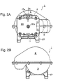
- FIG. 2A and FIG. 2B are a left and a right side view respectively of the scroll fluid machine of FIG. 1 showing external view
- FIG. 3 is a local sectional plan view of the scroll fluid machine of FIG. 1 showing the flow of cooling gas
- FIG. 4 is a section taken along lines A-A in FIG. 3 showing the longitudinal section of the scroll machine proper of FIG. 1
- FIG. 5 is another embodiment of a scroll fluid machine of the present invention showing the placement of a cooling fan.
- FIG. 1 is a scroll machine proper
- 2 is an upper cover
- 13 is a motor housing
- 2b is the arciform part of the upper cover 2
- 12 is a supporter plate
- 10 is a housing of the scroll machine proper 1
- 4 is a stationary scroll having cooling fins 4b and fixed to the housing 10
- 3 is a lower cover fixed to a base 27
- 17a is an inlet opening for cooling gas
- 20 is a front cover with an opening 20a in the center.
- FIG. 3 said upper cover 2 is removed and an electric motor 15 is shown in sectional view.
- An annular jacket 26 surrounds the motor housing 13, extends to the suction opening of a cooling fan 16 and is fixed to a supporter plate 25.
- the lower cover 3 and the upper cover 2 form when assembled a space 18 for accommodation of the fan 16 and a guide passage 19 for guiding the cooling gas to the scroll machine proper.
- the rotation shaft 9 of the motor 15 is rotationally supported by a pair of bearings in the supporter plate 12 and the supporter plate 25, and the cooling fan 16 is fixed at the end of the rotation shaft 9 in the rear (right side) of said motor 15.
- the cooling fan 16 is located in the space 18 formed by the upper cover 2 and the lower cover 3, and when rotated by the motor 15 induces air from the annular aperture 17a through the annular passage 17 and apertures formed in the supporter plate 25 in the outside part of the motor housing to the suction opening of the fan 16 as indicated by arrows 30 and 31.
- the cooling air blown out from the fan 16 radially outwardly flows to the guide passage 19 passing the corner 19a as indicated by arrows 32 and 33 and flows out from the guide passage 19 to the scroll machine proper at the outlet of the guide passage 19 as indicated by arrows 34 and 35.
- the cooling gas flowing along the outer side wall of the guide passage 19 turns its flow direction at the outlet part along a projected part 19d of the wall, but the succeeding inner side flow push the outer side flow, and as a result the flow quantity is evenly distributed to flow in the lateral side of the back sides of both scroll disks of the scroll machine proper as indicated by arrows 34 and 35.
- the scroll machine proper 1 shows a section taken along lines A-A in FIG. 3.
- the scroll machine proper comprises a stationary scroll 4, a revolving scroll 5, a housing 10, an auxiliary crank carrier 6, a drive shaft 7, and a support plate 12.
- the stationary scroll 4 which is fixed to the housing 10 has a spiral-shaped lap 4a embedded on the sliding surface 4g of the scroll disk and a number of cooling fins 4b on the back side of the disk extending in the direction perpendicular to the sheet of the drawing, that is, in the lateral direction.
- the revolving scroll 5 has a spiral-shaped lap 5a embedded on the sliding surface 5g of the scroll disk and a number of cooling fins on the back side of the disk extending in the direction perpendicular to the sheet of the drawing, that is, in the lateral direction.
- Fluid taken in from said inlet port 4c and compressed in the scroll chamber formed by spiral laps 4a, 5a and sliding surfaces 4g, 5g of both stationary and revolving scrolls 4, 5 is discharged from the discharge port 4d and flows out through a pipe, not shown, connected to the screw port 4e.
- top surfaces of the laps 4a and 5a are grooved for insertion of tip seals 22 made of such as fluorine group resin having self lubricating property to seal the fluid.
- tip seals 22 made of such as fluorine group resin having self lubricating property to seal the fluid.
- the drive shaft 7 having an offset potion 7a at the left end with its right end coupled to said rotation shaft 9 through a coupling 8 fixed to the end of the rotation shaft 9, is journalled on a bearing in the housing 10 and supports on the offset portion 7a the auxiliary crank carrier 6 by means of a bearing fit in the central hub of the auxiliary crank carrier 6.
- auxiliary crank 14 each having an offset portion of which the offset is same as that of the offset portion 7a of the drive shaft, are journalled on bearings in the housing 10 at circular intervals of 120° and the three offset portions of three auxiliary cranks 14 support the auxiliary crank carrier 6 by means of bearings in three bosses formed with circular intervals of 120° near the perimetral part of the auxiliary crank carrier 6 which is fixed to the revolving scroll on the back side behind the cooling fins 5b.
- the auxiliary crank carrier consequently the revolving scroll, revolve or orbit around the center of rotation of the drive shaft 9 with rotation of the drive shaft 9 without self rotation, the laps 4a and 5a intermesh each other, and the fluid taken in from said inlet port 4c is compressed toward the center to be discharged from said discharge port 4d.
- the cooling fan 16 attached to the rotation shaft 9 rotates and the cooling air is taken in from annular opening 17a.
- the cooling air then proceeds in the annular passage 17 cooling the motor 15 to the cooling fan to be sucked in, blown out cooling air from the fan 16 proceeds through the passage 19 to the outlet 19b and flow from the lateral side of the scroll machine proper 1 in the back side of the stationary and revolving scroll disks as indicated by arrows 34 and 35 and out flow as indicated by arrows 37and 36 cooling the both scrolls from the back sides by the medium of cooling fins.
- the flow loss in the annular passage 17 and in the guide passage 19 is small in those passages and as a result cooling gas is supplied efficiently for cooling the scroll machine proper.
- FIG. 5 shows another embodiment of the present invention.
- the present invention is applicable to a double lap scroll type which comprises a revolving scroll with laps on both side of its center disk and two stationary scrolls in both side of the revolving scroll for cooling the both back sides of the two stationary scrolls.
- cooling of the back side of revolving scroll is possible by providing a cooling passage, or passages in the center disk of larger thickness, or by composing a revolving scroll so that two disks having a scroll lap on one side of each disk are combined with each other on the back side opposite to the lap side keeping some distance between the back surface of the disks to secure a cooling gas passage.
- a cooling passage or passages in the center disk of larger thickness
- two disks having a scroll lap on one side of each disk are combined with each other on the back side opposite to the lap side keeping some distance between the back surface of the disks to secure a cooling gas passage.
- the tubular jacket 26 may be extended toward the scroll machine proper 1 or drawn back toward the motor 15. It is essential only that the proper length of the annular passage 17 for cooling the motor 15 be secured.
- the cooling gas may be taken in from openings provided on the circumferential surface of the tubular jacket 26 and arciform part of the upper 2 and lower cover 3.
- tubular jacket 26 keeps some distance all over the circumference from the outer circumferential surface of the motor 15 and the cooling gas contacts all over the outer circumferential surface of the motor 15, it may be acceptable to form a jacket so that it forms several tunnels on the said outer surface of the motor 15 and the cooling gas contacts said outer surface not all over the circumference but partly to secure the required cooling area for cooling the motor 15.
- the taken-in cooling air is introduced from a lateral side of the scroll machine proper in a direction crossing the longitudinal direction of the rotation shaft and forcibly cools the scroll disk from the backside, and sufficient cooling is performed efficiently.
Landscapes
- Engineering & Computer Science (AREA)
- Mechanical Engineering (AREA)
- General Engineering & Computer Science (AREA)
- Rotary Pumps (AREA)
- Applications Or Details Of Rotary Compressors (AREA)
Description
a tubular jacket is provided to surround at least a part of the outer circumferential surface of the electric motor keeping some distance from the outer circumferential surface to form an annular passage for cooling gas taken in by a cooling fan, which cooling gas flows into the annular passage from an annular aperture formed between the outer circumferential surface and an end of said tubular jacket;
a passage connecting to the annular passage is formed to guide and send out the cooling gas to a side of the scroll machine proper in a direction crossing the longitudinal direction of the rotation shaft; and
the cooling gas flows from one lateral side to the other lateral of the scroll machine proper to forcibly cool the back side of the scroll disk.
Claims (7)
- A scroll fluid machine in which a scroll machine proper (1) is driven by the rotation shaft (9) of a motor (15) and is forcedly cooled by the flow of a cooling gas taken in by a cooling fan (16) in one direction, wherein:a tubular jacket (26) surrounding at least part of the outer circumferential surface (13) of said motor (15) keeping some distance from the outer circumferential surface of said motor is provided wherein an inlet opening (17a) for taking in cooling gas by said cooling fan (16) is arranged;a passage (19) connected to the cooling space (17) formed between the outer circumferential surface (13) of said motor (15) and said tubular jacket (26) is composed for introducing said cooling gas taken in from said inlet opening (17a) to a lateral side of said scroll machine proper (1) and in a direction crossing the longitudinal direction of said rotation shaft (9); andsaid cooling gas flows from a lateral side to the other lateral side of said scroll machine proper (1) and forcibly cools the back side of a scroll disk of said scroll machine proper (1).
- A scroll fluid machine according to claim 1, wherein the back side of a scroll disk (5) and also the back side of the other scroll disk (4) disposed opposite to the former scroll disk to form a fluid compression chamber are cooled by the cooling gas flowing from a lateral side of the scroll disks.
- A scroll fluid machine according to claim 1, wherein the back side of a scroll disk (5) and the back side of the other scroll disk (4) include a number of cooling fins (46, 56) and said former scroll disk (5) is provided with a connecting device (6, 7) on the back side toward said motor (15) to be connected to the rotation shaft (9) of said motor.
- A scroll fluid machine according to any of claims 1 to 3, wherein the rotation shaft (9) of said motor (15) is connected to said scroll machine proper (1) at one end and connected to the cooling fan (16) at the other end, and said fan is rotated with rotation of said motor (15) to forcibly cool said scroll machine proper (1).
- A scroll fluid machine according to any of claims 1 to 4, wherein said cooling fan (16) is placed at the lateral side opposite to the lateral side where cooling gas is introduced to the back side of the scroll disk of said scroll machine proper (1).
- A scroll fluid machine according to any of claims 1 to 5, wherein turning corners in said passages from said inlet opening (17a) through to an outlet (19b) where the cooling gas is sent out to said scroll machine proper, at which turning corner the direction of cooling gas flow changes, are rounded.
- A scroll fluid machine according to any of claims 1 to 6, wherein a diverting means is provided to divert cooling gas flow to the back side of a scroll disk (5) and to that of the other scroll disk (4).
Applications Claiming Priority (2)
| Application Number | Priority Date | Filing Date | Title |
|---|---|---|---|
| JP29313998A JP4026099B2 (en) | 1998-10-15 | 1998-10-15 | Scroll fluid machinery |
| JP29313998 | 1998-10-15 |
Publications (2)
| Publication Number | Publication Date |
|---|---|
| EP0994258A1 EP0994258A1 (en) | 2000-04-19 |
| EP0994258B1 true EP0994258B1 (en) | 2004-01-02 |
Family
ID=17790934
Family Applications (1)
| Application Number | Title | Priority Date | Filing Date |
|---|---|---|---|
| EP99120545A Expired - Lifetime EP0994258B1 (en) | 1998-10-15 | 1999-10-15 | Scroll fluid machine |
Country Status (4)
| Country | Link |
|---|---|
| US (1) | US6190145B1 (en) |
| EP (1) | EP0994258B1 (en) |
| JP (1) | JP4026099B2 (en) |
| DE (1) | DE69913911T2 (en) |
Families Citing this family (45)
| Publication number | Priority date | Publication date | Assignee | Title |
|---|---|---|---|---|
| RU2193114C2 (en) * | 2000-06-23 | 2002-11-20 | Открытое акционерное общество "Научно-производственное предприятие "Микрон" | Air-cooled compression unit |
| RU2193690C2 (en) * | 2000-06-23 | 2002-11-27 | Открытое акционерное общество "Научно-производственное предприятие "Микрон" | Method of cooling compressor unit operating at "work-pause" mode |
| RU2194192C2 (en) * | 2000-06-23 | 2002-12-10 | Открытое акционерное общество "Научно-производственное предприятие "Микрон" | Compression unit for air cooling |
| JP4074075B2 (en) * | 2001-09-19 | 2008-04-09 | アネスト岩田株式会社 | Scroll fluid machinery |
| RU2213266C1 (en) * | 2002-05-06 | 2003-09-27 | Открытое акционерное общество "Научно-производственное предприятие "Микрон" | Method of cooling compression unit |
| RU2213267C1 (en) * | 2002-05-27 | 2003-09-27 | Открытое акционерное общество "Научно-производственное предприятие "Микрон" | Air cooling compression unit |
| US7309219B2 (en) * | 2003-12-26 | 2007-12-18 | Hitachi, Ltd. | Scroll type fluid machinery |
| FR2881189A1 (en) * | 2005-01-21 | 2006-07-28 | V G B Vulliez Gestion Brevets | VACUUM PUMP CIRCULAR CIRCULAR TRANSLATION CYCLE WITH SEVERAL TREES |
| JP4629546B2 (en) * | 2005-09-30 | 2011-02-09 | アネスト岩田株式会社 | Scroll fluid machinery |
| US10683865B2 (en) | 2006-02-14 | 2020-06-16 | Air Squared, Inc. | Scroll type device incorporating spinning or co-rotating scrolls |
| US8668479B2 (en) * | 2010-01-16 | 2014-03-11 | Air Squad, Inc. | Semi-hermetic scroll compressors, vacuum pumps, and expanders |
| US8523544B2 (en) | 2010-04-16 | 2013-09-03 | Air Squared, Inc. | Three stage scroll vacuum pump |
| US10221852B2 (en) | 2006-02-14 | 2019-03-05 | Air Squared, Inc. | Multi stage scroll vacuum pumps and related scroll devices |
| JP5048303B2 (en) * | 2006-10-31 | 2012-10-17 | 株式会社日立産機システム | Scroll type fluid machine |
| JP2008157179A (en) * | 2006-12-26 | 2008-07-10 | Anest Iwata Corp | Scroll fluid machine |
| US8177534B2 (en) * | 2008-10-30 | 2012-05-15 | Advanced Scroll Technologies (Hangzhou), Inc. | Scroll-type fluid displacement apparatus with improved cooling system |
| JP5314456B2 (en) * | 2009-02-27 | 2013-10-16 | アネスト岩田株式会社 | Air-cooled scroll compressor |
| JP5286108B2 (en) * | 2009-03-02 | 2013-09-11 | 株式会社日立産機システム | Scroll type fluid machine |
| JP2011080366A (en) * | 2009-10-02 | 2011-04-21 | Anest Iwata Corp | Motor-directly connected compressor unit |
| US11047389B2 (en) | 2010-04-16 | 2021-06-29 | Air Squared, Inc. | Multi-stage scroll vacuum pumps and related scroll devices |
| JP5769332B2 (en) * | 2010-06-02 | 2015-08-26 | アネスト岩田株式会社 | Scroll expander |
| US20130232975A1 (en) | 2011-08-09 | 2013-09-12 | Robert W. Saffer | Compact energy cycle construction utilizing some combination of a scroll type expander, pump, and compressor for operating according to a rankine, an organic rankine, heat pump, or combined organic rankine and heat pump cycle |
| JP5998028B2 (en) * | 2012-11-30 | 2016-09-28 | 株式会社日立産機システム | Scroll type fluid machine |
| US9611852B2 (en) * | 2013-03-29 | 2017-04-04 | Agilent Technology, Inc. | Thermal/noise management in a scroll pump |
| US10208753B2 (en) | 2013-03-29 | 2019-02-19 | Agilent Technologies, Inc. | Thermal/noise management in a scroll pump |
| BE1022028B1 (en) * | 2013-04-05 | 2016-02-04 | Atlas Copco Airpower, Naamloze Vennootschap | HOUSING FOR A FAN OF A SPIRAL COMPRESSOR |
| JP6279926B2 (en) * | 2014-02-17 | 2018-02-14 | 三菱重工業株式会社 | Scroll compressor |
| JP6419456B2 (en) * | 2014-05-15 | 2018-11-07 | ナブテスコ株式会社 | Air compressor for vehicle |
| JP6325336B2 (en) * | 2014-05-15 | 2018-05-16 | ナブテスコ株式会社 | Air compressor unit for vehicles |
| US10508543B2 (en) | 2015-05-07 | 2019-12-17 | Air Squared, Inc. | Scroll device having a pressure plate |
| CN105526164A (en) * | 2016-01-26 | 2016-04-27 | 东莞市康驰实业有限公司 | A vehicle-mounted DC direct-coupled oil-free scroll air compressor |
| EP3486490B1 (en) * | 2016-07-15 | 2021-03-31 | Hitachi Industrial Equipment Systems Co., Ltd. | Motor-integrated fluid machine |
| CN108700068B (en) * | 2016-08-03 | 2020-06-19 | 株式会社日立产机系统 | Scroll Fluid Machinery |
| US10865793B2 (en) | 2016-12-06 | 2020-12-15 | Air Squared, Inc. | Scroll type device having liquid cooling through idler shafts |
| JP2018135855A (en) * | 2017-02-23 | 2018-08-30 | アネスト岩田株式会社 | Scroll fluid machine and manufacturing method of the same |
| EP3788262B1 (en) * | 2018-05-04 | 2024-11-20 | Air Squared, Inc. | Liquid cooling of fixed and orbiting scroll compressor, expander or vacuum pump |
| US20200025199A1 (en) | 2018-07-17 | 2020-01-23 | Air Squared, Inc. | Dual drive co-rotating spinning scroll compressor or expander |
| US11067080B2 (en) | 2018-07-17 | 2021-07-20 | Air Squared, Inc. | Low cost scroll compressor or vacuum pump |
| US11530703B2 (en) | 2018-07-18 | 2022-12-20 | Air Squared, Inc. | Orbiting scroll device lubrication |
| US11473572B2 (en) | 2019-06-25 | 2022-10-18 | Air Squared, Inc. | Aftercooler for cooling compressed working fluid |
| JP7005728B2 (en) * | 2020-11-12 | 2022-01-24 | 株式会社日立産機システム | Scrolling fluid machine |
| US11898557B2 (en) | 2020-11-30 | 2024-02-13 | Air Squared, Inc. | Liquid cooling of a scroll type compressor with liquid supply through the crankshaft |
| US11885328B2 (en) | 2021-07-19 | 2024-01-30 | Air Squared, Inc. | Scroll device with an integrated cooling loop |
| US12510080B2 (en) * | 2022-12-15 | 2025-12-30 | Agilent Technologies, Inc. | Fluid pump and enclosure providing stator holder and cooling for motor and electronics |
| CN116163956B (en) * | 2023-02-28 | 2024-11-22 | 江苏曼淇威电气产品有限公司 | Scroll compressor |
Family Cites Families (13)
| Publication number | Priority date | Publication date | Assignee | Title |
|---|---|---|---|---|
| US3134369A (en) * | 1961-03-08 | 1964-05-26 | Nsu Motorenwerke Ag | Air cooling of rotary-piston engines |
| JPS58146894A (en) | 1982-02-26 | 1983-09-01 | 株式会社日立製作所 | Radiation exposure reduction system in case of main steam pipe rupture accident |
| JPS63100294A (en) * | 1986-10-17 | 1988-05-02 | Mitsui Seiki Kogyo Co Ltd | Scroll compressor |
| DE3831703C1 (en) * | 1988-09-17 | 1990-03-08 | Peter 4355 Waltrop De Wilms | |
| JP2816201B2 (en) * | 1989-10-13 | 1998-10-27 | 株式会社日立製作所 | Scroll compressor |
| JP2822070B2 (en) * | 1989-10-30 | 1998-11-05 | 三井精機工業株式会社 | Cooling system for whole-system rotary scroll compressor |
| JPH0571472A (en) * | 1991-03-01 | 1993-03-23 | Sanden Corp | Gas compressor |
| JP3130588B2 (en) | 1991-10-04 | 2001-01-31 | 株式会社東芝 | Storage media |
| JPH06129383A (en) * | 1992-10-20 | 1994-05-10 | Tokico Ltd | Package type gas compressor |
| JP3199141B2 (en) | 1993-07-07 | 2001-08-13 | ソニー株式会社 | Drum lead measuring device and measuring method |
| US5417554A (en) * | 1994-07-19 | 1995-05-23 | Ingersoll-Rand Company | Air cooling system for scroll compressors |
| US5551846A (en) * | 1995-12-01 | 1996-09-03 | Ford Motor Company | Scroll compressor capacity control valve |
| JPH1026090A (en) | 1996-07-08 | 1998-01-27 | Asuka Japan:Kk | Ventilation-cooled scroll fluid machine |
-
1998
- 1998-10-15 JP JP29313998A patent/JP4026099B2/en not_active Expired - Lifetime
-
1999
- 1999-10-15 EP EP99120545A patent/EP0994258B1/en not_active Expired - Lifetime
- 1999-10-15 US US09/419,081 patent/US6190145B1/en not_active Expired - Lifetime
- 1999-10-15 DE DE69913911T patent/DE69913911T2/en not_active Expired - Lifetime
Also Published As
| Publication number | Publication date |
|---|---|
| JP4026099B2 (en) | 2007-12-26 |
| US6190145B1 (en) | 2001-02-20 |
| EP0994258A1 (en) | 2000-04-19 |
| DE69913911D1 (en) | 2004-02-05 |
| JP2000120568A (en) | 2000-04-25 |
| DE69913911T2 (en) | 2004-11-04 |
Similar Documents
| Publication | Publication Date | Title |
|---|---|---|
| US6190145B1 (en) | Scroll fluid machine | |
| JP7042265B2 (en) | Turbo compressor with separate cooling air passages | |
| CN100489310C (en) | Scroll fluid machine | |
| US7309219B2 (en) | Scroll type fluid machinery | |
| KR860001100B1 (en) | Ventilation device of rotating electric | |
| KR100572849B1 (en) | Turbo blower with simple structure for efficient motor cooling | |
| EP2224136A2 (en) | Air-cooled scroll compressor | |
| KR100813154B1 (en) | Scroll fluid machine | |
| CA2535389C (en) | Compressor assemblage comprising an air-cooled electric motor | |
| US4659950A (en) | Charging generator for a vehicle | |
| JP2020156264A (en) | Rotating machine and rotor shaft | |
| JP4828915B2 (en) | Scroll type fluid machine | |
| WO2018011970A1 (en) | Motor-integrated fluid machine | |
| KR100604734B1 (en) | Compressor machine with two counter-rotating rotors | |
| JPH0953589A (en) | Scroll type fluid machinery | |
| KR101942422B1 (en) | Cooling structure for permanent magnet motor of turbo blower | |
| KR102005552B1 (en) | Turbo blower with Cooling Apparatus | |
| CA2151533A1 (en) | Refrigeration fan system | |
| JPH10176668A (en) | Air cooled package type oil feeding compressor | |
| JP2000045972A (en) | Scroll type fluid machine | |
| JP4625193B2 (en) | Scroll type fluid machine | |
| JP3653128B2 (en) | Scroll type fluid machine | |
| JP2005139976A (en) | Scroll type fluid machine | |
| JPH08177764A (en) | Scroll type fluid machinery | |
| CN215566891U (en) | Air compressor |
Legal Events
| Date | Code | Title | Description |
|---|---|---|---|
| PUAI | Public reference made under article 153(3) epc to a published international application that has entered the european phase |
Free format text: ORIGINAL CODE: 0009012 |
|
| AK | Designated contracting states |
Kind code of ref document: A1 Designated state(s): BE DE FR IT |
|
| AX | Request for extension of the european patent |
Free format text: AL;LT;LV;MK;RO;SI |
|
| 17P | Request for examination filed |
Effective date: 20000928 |
|
| AKX | Designation fees paid |
Free format text: BE DE FR IT |
|
| GRAH | Despatch of communication of intention to grant a patent |
Free format text: ORIGINAL CODE: EPIDOS IGRA |
|
| GRAH | Despatch of communication of intention to grant a patent |
Free format text: ORIGINAL CODE: EPIDOS IGRA |
|
| GRAA | (expected) grant |
Free format text: ORIGINAL CODE: 0009210 |
|
| AK | Designated contracting states |
Kind code of ref document: B1 Designated state(s): BE DE FR IT |
|
| REF | Corresponds to: |
Ref document number: 69913911 Country of ref document: DE Date of ref document: 20040205 Kind code of ref document: P |
|
| ET | Fr: translation filed | ||
| PLBE | No opposition filed within time limit |
Free format text: ORIGINAL CODE: 0009261 |
|
| STAA | Information on the status of an ep patent application or granted ep patent |
Free format text: STATUS: NO OPPOSITION FILED WITHIN TIME LIMIT |
|
| 26N | No opposition filed |
Effective date: 20041005 |
|
| PG25 | Lapsed in a contracting state [announced via postgrant information from national office to epo] |
Ref country code: IT Free format text: LAPSE BECAUSE OF NON-PAYMENT OF DUE FEES;WARNING: LAPSES OF ITALIAN PATENTS WITH EFFECTIVE DATE BEFORE 2007 MAY HAVE OCCURRED AT ANY TIME BEFORE 2007. THE CORRECT EFFECTIVE DATE MAY BE DIFFERENT FROM THE ONE RECORDED. Effective date: 20051015 |
|
| PGRI | Patent reinstated in contracting state [announced from national office to epo] |
Ref country code: IT Effective date: 20091201 |
|
| REG | Reference to a national code |
Ref country code: FR Ref legal event code: PLFP Year of fee payment: 17 |
|
| REG | Reference to a national code |
Ref country code: FR Ref legal event code: PLFP Year of fee payment: 18 |
|
| REG | Reference to a national code |
Ref country code: FR Ref legal event code: PLFP Year of fee payment: 19 |
|
| PGFP | Annual fee paid to national office [announced via postgrant information from national office to epo] |
Ref country code: DE Payment date: 20171019 Year of fee payment: 19 Ref country code: FR Payment date: 20171024 Year of fee payment: 19 |
|
| PGFP | Annual fee paid to national office [announced via postgrant information from national office to epo] |
Ref country code: BE Payment date: 20171019 Year of fee payment: 19 Ref country code: IT Payment date: 20171023 Year of fee payment: 19 |
|
| REG | Reference to a national code |
Ref country code: DE Ref legal event code: R119 Ref document number: 69913911 Country of ref document: DE |
|
| REG | Reference to a national code |
Ref country code: BE Ref legal event code: MM Effective date: 20181031 |
|
| PG25 | Lapsed in a contracting state [announced via postgrant information from national office to epo] |
Ref country code: DE Free format text: LAPSE BECAUSE OF NON-PAYMENT OF DUE FEES Effective date: 20190501 |
|
| PG25 | Lapsed in a contracting state [announced via postgrant information from national office to epo] |
Ref country code: FR Free format text: LAPSE BECAUSE OF NON-PAYMENT OF DUE FEES Effective date: 20181031 Ref country code: BE Free format text: LAPSE BECAUSE OF NON-PAYMENT OF DUE FEES Effective date: 20181031 |
|
| PG25 | Lapsed in a contracting state [announced via postgrant information from national office to epo] |
Ref country code: IT Free format text: LAPSE BECAUSE OF NON-PAYMENT OF DUE FEES Effective date: 20181015 |