EP0993553B1 - Sealing device on a shaft journal of a dry-running helical rotary compressor - Google Patents
Sealing device on a shaft journal of a dry-running helical rotary compressor Download PDFInfo
- Publication number
- EP0993553B1 EP0993553B1 EP99948560A EP99948560A EP0993553B1 EP 0993553 B1 EP0993553 B1 EP 0993553B1 EP 99948560 A EP99948560 A EP 99948560A EP 99948560 A EP99948560 A EP 99948560A EP 0993553 B1 EP0993553 B1 EP 0993553B1
- Authority
- EP
- European Patent Office
- Prior art keywords
- seal
- ring
- sealing
- oil
- rotor
- Prior art date
- Legal status (The legal status is an assumption and is not a legal conclusion. Google has not performed a legal analysis and makes no representation as to the accuracy of the status listed.)
- Expired - Lifetime
Links
Images

Classifications
-
- F—MECHANICAL ENGINEERING; LIGHTING; HEATING; WEAPONS; BLASTING
- F16—ENGINEERING ELEMENTS AND UNITS; GENERAL MEASURES FOR PRODUCING AND MAINTAINING EFFECTIVE FUNCTIONING OF MACHINES OR INSTALLATIONS; THERMAL INSULATION IN GENERAL
- F16J—PISTONS; CYLINDERS; SEALINGS
- F16J15/00—Sealings
- F16J15/002—Sealings comprising at least two sealings in succession
- F16J15/004—Sealings comprising at least two sealings in succession forming of recuperation chamber for the leaking fluid
-
- F—MECHANICAL ENGINEERING; LIGHTING; HEATING; WEAPONS; BLASTING
- F04—POSITIVE - DISPLACEMENT MACHINES FOR LIQUIDS; PUMPS FOR LIQUIDS OR ELASTIC FLUIDS
- F04C—ROTARY-PISTON, OR OSCILLATING-PISTON, POSITIVE-DISPLACEMENT MACHINES FOR LIQUIDS; ROTARY-PISTON, OR OSCILLATING-PISTON, POSITIVE-DISPLACEMENT PUMPS
- F04C27/00—Sealing arrangements in rotary-piston pumps specially adapted for elastic fluids
- F04C27/008—Sealing arrangements in rotary-piston pumps specially adapted for elastic fluids for other than working fluid, i.e. the sealing arrangements are not between working chambers of the machine
- F04C27/009—Shaft sealings specially adapted for pumps
Definitions
- From DE-A 24 41 520 is a shaft seal for one Screw rotor compressor with water injection known which has a plurality of sealing collars surrounding the rotor journal, between which there are annular chambers, one of which Annular chamber with gas compressed by the compressor as sealing gas is acted upon and another chamber a drainage chamber for bearing oil drainage.
- the sealing collars are labyrinth sealing collars, one of them can also be a touch seal his.
- This shaft seal is a dynamic one Seal that uses sealing gas under pressure, which from the Delivery gas flow of the compressor must be branched off and therefore means a loss of performance.
- the invention has for its object one without sealing gas working sealing arrangement with a particularly high Sealing effect and nevertheless good wear resistance for one Shaft journal of a dry running rotary screw compressor to accomplish.
- Fig. 1 is a section of an axial section through a Screw compressor and shows schematically one of the rotors, e.g. the main rotor (rib rotor) 1, the shaft journal 3 is mounted in the housing 5 by a roller bearing 7.
- the roller bearing 7 is oil-lubricated, preferably by a Lubrication device (not shown) that has an oil mist generated.
- a housing ring firmly connected to this 9 used.
- a labyrinth gap seal 11 in the form of several side by side Shaped ring ribs. This works without contact with the cylindrical peripheral surface of a section 3a of the shaft journal 3 together to seal the gas to effect.
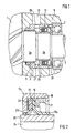
- the lip seal ring 13 shown in Fig. 2 consists of an outer retaining ring 15 and an inner retaining ring 17, between which two lip rings 19, 21 and a flat seal 23 are clamped, which are made of flexible, elastomeric Materials exist.
- the sealing lips 19a, 21a of the two Lip rings 19, 21 are of different lengths.
- the sealing lip 19a of the lip ring 19, which in the direction of the bearing 7 is bent out, is longer than the sealing lip 21a Sealing rings 21 which are bent in the direction of the rotor is.
- a race 25 In the area of the lip seal ring 13 is on a section 3b of the shaft journal 3 fastened a race 25, preferably shrunk.
- the race 25, which e.g. a commercial one Race for a rolling bearing can exist made of steel with a specially hardened peripheral surface on which the Lips 19a and 21a of lip seal ring 13 rest.
- the outer diameter of the race 25 is smaller than the outer diameter the cooperating with the labyrinth seal 11 Section 3a of the shaft journal.
- the hardened and extremely precisely machined, e.g. polished, Outer surface of the race 25 results in a particularly wear-reducing Contact surface for the sealing lips of the lip sealing ring 13.
- the lip rings 19, 21 are preferably made made of an elastomeric material based on fluorocarbon polymer.
- a circumferential annular groove 27 formed through an opening 29 of the housing ring 9 with a space 31 of the housing open to the atmosphere 5 is connected.
- a ring 33 fastened with an outer flange, that forms a spray umbrella that gives direct access of oil droplets injected into the bearing 7 for Lip seal ring 13 prevented.
- the labyrinth gap seal acts when the screw compressor is in operation 11 in the usual way as a gas seal, while the lip seal ring 13 as an oil seal with a particularly high Sealing acts, causing oil leakage from the bearing 7 past the lip seal ring 13 in the direction of the Labyrinth seal 11 is prevented with high security.
- the lying in the area of the annular groove 27 of the housing ring 9 Step between the outer surface of the race 25 and the outer surface of section 3a of the shaft journal acts on one Oil creeps along the surface. any volatile components of the oil that are in the range of Ring groove 27 escape through the vent 29 to the outside air.
- FIG. 3 is the Shaft journal 3 of the dry-running rotor 1 of a screw compressor in the housing 5 by means of oil or grease lubrication Rolling bearings 7 stored in the housing 5.
- a second Rotor, which engages with the rotor 1 in a known manner is indicated at 2.
- a lip seal ring 13 adjacent to the roller bearing 7 and a labyrinth sealing ring 11 adjacent to the rotor 1 is used.
- annular space 27 which a ventilation opening 29 with a ventilation channel 31 of the Housing is connected and through this with the outside air in Connection is established.
- a race 25 of such axial length attached e.g. B. shrunk that he does not only interacts with the lip seal ring 13, but itself also extends over the area of the labyrinth sealing ring 11.
- the one specially hardened as in the previous embodiment and polished race 25 does not have one in the normal case Contact with the lip seal 11. But it should through a malfunction to a contact between the lip seal ring 11 and the race 25 come, so is not the shaft journal 3, but only the Race 25 damaged, so that simply changing the Race 25 the perfect sealing condition is restored can be.
- the extended race has 3 the further advantage that it is used as a spacer between the end face 1a of the rotor 1 and the roller bearings 7 can serve. This is only possible through exact dimensioning of the axial length of the race 25 at the same time the frontal gap between the front surface 1a of the Rotor 1 and the corresponding end face of the housing 5 set very precisely.
Description
Bei trockenlaufenden Rotationsschraubenverdichtern wird dem Verdichterraum kein Öl für Schmierung, Kühlung und Abdichtung zwischen den Rotoren zugeführt. Die Rippen des Hauptläufers und Nuten des Nebenläufers greifen "trocken" und trotzdem abdichtend ineinander. Solche Schraubenverdichter sind aufgrund der Ölfreiheit des Verdichterraums besonders geeignet für die Anwendung in pneumatischen Fördereinrichtungen, z.B. für das Befüllen und Entleeren von Silos, Tanks, Tankfahrzeugen und dgl. mit Schüttgütern. Insbesondere bei der pneumatischen Förderung von empfindlichen Gütern wie Lebensmitteln oder Chemikalien ist es wichtig, daß der Förderluftstrom in hohem Maße frei von Ölanteilen ist.In the case of dry-running rotary screw compressors, the Compressor room no oil for lubrication, cooling and sealing fed between the rotors. The ribs of the main runner and grooves of the secondary rotor grip "dry" and nevertheless sealing into each other. Such screw compressors are special because of the absence of oil in the compressor chamber suitable for use in pneumatic conveyors, e.g. for filling and emptying silos, Tanks, tank vehicles and the like with bulk goods. In particular in the pneumatic conveying of sensitive goods like food or chemicals, it is important that the conveying air flow is largely free of oil.
Bei trockenlaufenden Schraubenrotoren muß durch geeignete Abdichtung der Wellenzapfen verhindert werden, daß Öl aus den ölgeschmierten Lagern der Wellenzapfen durch Leckage entlang den Wellenzapfen in den Verdichterraum gelangt. Aus GB-A-1189856 und EP-A-0859154 ist es bereits bekannt, auf den Wellenzapfen eines Rotationsschraubenverdichters nebeneinander einen gewöhnlichen Dichtring und einen Öldichtring anzuordnen, die voneinander durch einen mit der Außenluft verbundenen Ringraum getrennt sind. Gewöhnliche Dichtringe sind jedoch zur Abdichtung von schnell rotierenden Wellenzapfen, die Umfangsgeschwindigkeiten von 55 - 150 m/sec erreichen können, wegen des hohen Verschleisses ungeeignet. Es ist andererseits bekannt, den Wellenzapfen eines trockenlaufenden Rotationsschraubenverdichters durch zwei nebeneinanderliegende, berührungsfreie Labyrinthdichtungen abzudichten, von denen die dem ölgeschmierten Lager näher liegende Labyrinthdichtung in Form eines Ölrückführgewindes ausgebildet ist. Es hat sich jedoch gezeigt, daß solche berührungsfreien Labyrinthdichtungen die Leckage von Öl entlang dem Wellenzapfen zum Verdichterraum, insbesondere bei hohem Drukkunterschied an der Saugseite des Verdichters, nicht immer zuverlässig verhindern können.In the case of dry-running screw rotors, suitable Sealing the shaft journal prevents oil from spilling out the oil-lubricated bearings of the shaft journals due to leakage reaches the compressor chamber along the shaft journals. Out GB-A-1189856 and EP-A-0859154 it is already known on the shaft journal of a rotary screw compressor next to one another Sealing ring and an oil seal to arrange the from each other through an annular space connected to the outside air are separated. Ordinary sealing rings are, however Sealing of rapidly rotating shaft journals, the peripheral speeds can reach from 55 - 150 m / sec, unsuitable due to the high wear. On the other hand, it is known, the shaft journal of a dry-running rotary screw compressor by two side by side, to seal non-contact labyrinth seals, from which the labyrinth seal closer to the oil-lubricated bearing in the form of an oil return thread is. However, it has been shown that such non-contact Maze seals the leakage of oil along the shaft journal to the compressor room, especially if there is a high pressure difference on the suction side of the compressor, not always can reliably prevent.
Aus DE-A 24 41 520 ist eine Wellendichtung für einen Schraubenrotorverdichter mit Wassereinspritzung bekannt, die mehrere den Rotorzapfen umgebende Dichtungsbunde aufweist, zwischen denen Ringkammern liegen, von denen eine Ringkammer mit vom Verdichter verdichtetem Gas als Sperrgas beaufschlagt wird und eine andere Kammer eine Drainagekammer für Lageröldrainage ist. Die Dichtungsbunde sind Labyrinthdichtungsbunde, einer davon kann auch eine Berührungsdichtung sein. Diese Wellendichtung ist eine dynamische Dichtung, die Sperrgas unter Druck verwendet, welches vom Fördergasstrom des Verdichters abgezweigt werden muß und deshalb einen Leistungsverlust bedeutet.From DE-A 24 41 520 is a shaft seal for one Screw rotor compressor with water injection known which has a plurality of sealing collars surrounding the rotor journal, between which there are annular chambers, one of which Annular chamber with gas compressed by the compressor as sealing gas is acted upon and another chamber a drainage chamber for bearing oil drainage. The sealing collars are labyrinth sealing collars, one of them can also be a touch seal his. This shaft seal is a dynamic one Seal that uses sealing gas under pressure, which from the Delivery gas flow of the compressor must be branched off and therefore means a loss of performance.
Der Erfindung liegt die Aufgabe zugrunde, eine ohne Sperrgas arbeitende Dichtungsanordnung mit besonders hoher Dichtwirkung und trotzdem guter Verschleißfestigeit für einen Wellenzapfen eines trockenlaufenden Rotationsschraubenverdichters zu schaffen.The invention has for its object one without sealing gas working sealing arrangement with a particularly high Sealing effect and nevertheless good wear resistance for one Shaft journal of a dry running rotary screw compressor to accomplish.
Die erfindungsgemäße Lösung der Aufgabe ist im Anspruch 1 angegeben. Die Unteransprüche beziehen sich auf vorteilhafte weitere Ausgestaltungen der Erfindung.The achievement of the object is in claim 1 specified. The sub-claims relate to advantageous further refinements of the invention.
Eine Ausführungsform der Erfindung wird anhand der Zeichnungen
näher erläutert. Es zeigt:
Fig. 1 ist ein Ausschnitt aus einem Axialschnitt durch einen
Schraubenkompressor und zeigt schematisch einen der Rotoren,
z.B. den Hauptläufer (Rippenrotor) 1, dessen Wellenzapfen
3 im Gehäuse 5 durch ein Wälzlager 7 gelagert ist.
Das Wälzlager 7 ist ölgeschmiert, vorzugsweise durch eine
Schmiereinrichtung (nicht dargestellt), die einen Ölnebel
erzeugt.Fig. 1 is a section of an axial section through a
Screw compressor and shows schematically one of the rotors,
e.g. the main rotor (rib rotor) 1, the shaft journal
3 is mounted in the
In das Gehäuse 5 ist ein mit diesem fest verbundener Gehäusering
9 eingesetzt. In dem dem Rotor 1 näher liegenden Abschnitt
des Gehäuserings 1 ist an dessen innerer Umfangsfläche
eine Labyrinthspaltdichtung 11. in Form mehrerer nebeneinanderliegender
Ringrippen angeformt. Diese wirkt berührungsfrei
mit der zylindrischen Umfangsfläche eines Abschnitts
3a des Wellenzapfens 3 zusammen, um die Gasabdichtung
zu bewirken.In the
An dem dem Wälzlager 7 näher liegenden Abschnitt des Gehäuserings
9 ist in den Gehäusering 9 ein Lippendichtring 13
eingesetzt, der in Fig. 2 mehr im Detail dargestellt ist.At the section of the housing ring closer to the rolling bearing 7
9 is a
Der in Fig. 2 dargestellte Lippendichtring 13 besteht aus
einem äußeren Haltering 15 und einem inneren Haltering 17,
zwischen denen zwei Lippenringe 19, 21 und eine Flachdichtung
23 eingespannt sind, die aus flexiblen, elastomeren
Materialien bestehen. Die Dichtlippen 19a, 21a der beiden
Lippenringe 19, 21 sind unterschiedlich lang. Die Dichtlippe
19a des Lippenrings 19, die in Richtung auf das Lager 7
hin abgebogen ist, ist länger als die Dichtlippe 21a des
Dichtrings 21, die in Richtung auf den Rotor hin abgebogen
ist.The
Im Bereich des Lippendichtrings 13 ist auf einen Abschnitt
3b des Wellenzapfens 3 ein Laufring 25 befestigt, vorzugsweise
aufgeschrumpft. Der Laufring 25, der z.B. ein handelsüblicher
Laufring für ein Wälzlager sein kann, besteht
aus Stahl mit speziell gehärteter Umfangsfläche, an der die
Lippen 19a und 21a des Lippendichtrings 13 anliegen. Der
Außendurchmesser des Laufringes 25 ist kleiner als der Außendurchmesser
des mit der Labyrinthdichtung 11 zusammenwirkenden
Abschnitts 3a des Wellenzapfens.In the area of the
Die gehärtete und extrem präzis bearbeitete, z.B. polierte,
Außenfläche des Laufrings 25 ergibt eine besonders verschleißmindernde
Anlagefläche für die Dichtlippen des Lippendichtrings
13. Die Lippenringe 19, 21 bestehen vorzugsweise
aus einem elastomeren Material auf der Basis von Fluorkohlenwasserstoffpolymer.The hardened and extremely precisely machined, e.g. polished,
Outer surface of the
In dem Gehäusering 9 ist zwischen der Labyrinthspaltdichtung
11 und dem Lippendichtring 13 eine umlaufende Ringnut
27 ausgebildet, die durch eine Öffnung 29 des Gehäuserings
9 mit einem zur Atmosphäre hin offenen Raum 31 des Gehäuses
5 verbunden ist.In the
Zwischen dem Lager 7 und dem Lippendichtring 13 ist auf dem
Wellenzapfen 3 ein Ring 33 mit einem Außenflansch befestigt,
der einen Spritzschirm bildet, der den direkten Zutritt
von in das Lager 7 eingespritzten Öltröpfchen zum
Lippendichtring 13 verhindert.Between the
Im Betrieb des Schraubenverdichters wirkt die Labyrinthspaltdichtung
11 in üblicher Weise als Gasdichtung, während
der Lippendichtring 13 als Öldichtung mit besonders hoher
Dichtwirkung wirkt, wodurch die Leckage von Öl aus dem Lager
7 an dem Lippendichtring 13 vorbei in Richtung auf die
Labyrinthdichtung 11 mit hoher Sicherheit verhindert wird.
Die im Bereich der Ringnut 27 des Gehäuserings 9 liegende
Stufe zwischen der Außenfläche des Laufrings 25 und der Außenfläche
des Abschnitts 3a des Wellenzapfens wirkt einem
Kriechen von Öl entlang der Oberfläche entgegen. Etwaige
flüchtige Bestandteile des Öls, die in den Bereich der
Ringnut 27 gelangen, entweichen über die Lüftungsöffnung 29
an die Außenluft.The labyrinth gap seal acts when the screw compressor is in
Bei der in Fig. 3 dargestellten Ausführungsform ist der
Wellenzapfen 3 des trockenlaufenden Rotors 1 eines Schraubenkompressors
in dem Gehäuse 5 mittels öl- oder fettgeschmierten
Wälzlagern 7 im Gehäuse 5 gelagert. Ein zweiter
Rotor, der mit dem Rotor 1 in bekannter Weise ein Eingriff
ist, ist bei 2 angedeutet.In the embodiment shown in Fig. 3 is the
Shaft journal 3 of the dry-running rotor 1 of a screw compressor
in the
Wie bei der Ausführungsform nach Fig. 1 sind in dem Gehäuse
5 ein dem Wälzlager 7 benachbarter Lippendichtring 13 und
ein dem Rotor 1 benachbarter Labyrinthdichtring 11 eingesetzt.
Dazwischen befindet sich ein Ringraum 27, der über
eine Lüftungsöffnung 29 mit einem Entlüftungskanal 31 des
Gehäuses verbunden ist und über diesen mit der Außenluft in
Verbindung steht. As in the embodiment of Fig. 1 are in the housing
5 a
Auf dem Wellenzapfen 3 ist ein Laufring 25 von solcher
axialen Länge befestigt, z. B. aufgeschrumpft, daß er nicht
nur mit dem Lippendichtring 13 zusammenwirkt, sondern sich
auch über den Bereich des Labyrinthdichtrings 11 erstreckt.
Der wie bei der voherigen Ausführungsform speziell gehärtete
und polierte Laufring 25 hat zwar im normalen Fall keine
Berührung mit dem Lippendichtring 11. Sollte es aber doch
einmal durch eine Betriebsstörung zu einer Berührung zwischen
dem Lippendichtring 11 und dem Laufring 25 kommen, so
wird hierdurch nicht der Wellenzapfen 3, sondern nur der
Laufring 25 beschädigt, so daß durch bloßes Auswechseln des
Laufrings 25 der einwandfreie Dichtungszustand wieder hergestellt
werden kann. Außerdem hat der verlängerte Laufring
gemäß Fig. 3 den weiteren Vorteil, daß er als Abstandshalter
zwischen der Stirnfläche 1a des Rotors 1 und den Wälzlagern
7 dienen kann. Hierdurch wird erst möglich, durch
exakte Bemessung der Axiallänge des Laufrings 25 gleichzeitig
den stirnseitigen Spalt zwischen der Stirnfläche 1a des
Rotors 1 und der entsprechenden Stirnfläche des Gehäuses 5
sehr präzise einzustellen.On the shaft journal 3 is a
Claims (6)
- Sealing arrangement on a rotor shaft peg of a dry-running rotary screw compressor for establishing a seal between the rotor (1) and an oil-lubricated bearing (7) of the shaft peg (3), characterized in that a housing ring (9) surrounding the shaft peg (3) presents in its section located closer to the rotor (1) a labyrinth gap seal (11) formed on the internal circumferential surface thereof and in its section located closer to the oil-lubricated bearing (7) bears a lip seal ring (13), and between said seals it has a ring groove (27) with ventilation opening (29) towards the outside, and
in that said shaft peg (3) presents a cylindrical circumferential surface (3 a) opposite the labyrinth gap seal (11) and a bearing race (25) made of hardened material, which is attached to said shaft peg and works in cooperation with the lip seal ring (13). - Sealing arrangement according to Claim 1, characterized in that the lip seal ring (13) presents two sealing lips (19a, 21a), which are bent in opposite directions, and are in contact with said bearing race, the longer sealing lip (19a) being directed towards the oil-lubricated bearing (7).
- Sealing arrangement according to Claim 1 or 2, characterized in that between the oil-lubricated bearing (7) and the lip seal ring (13) a ring-shaped spray shield (33) is arranged.
- Sealing arrangement according to one of Claims 1-3, characterized in that the bearing race (25) has a smaller external diameter than the circumferential surface (3a) of the shaft peg, which is located opposite the labyrinth gap seal (11).
- Sealing arrangement according to one of Claims 1-3, characterized in that the bearing race (25) also forms the circumferential surface of the shaft peg, located opposite the labyrinth slit seal (11).
- Dry-running rotation screw compressor, in which each one of the four shaft pegs at the suction- and pressure-side ends of the main rotor and the secondary rotor forms a seal with a sealing arrangement according to one of Claims 1-5.
Applications Claiming Priority (3)
| Application Number | Priority Date | Filing Date | Title |
|---|---|---|---|
| DE29807796U | 1998-04-30 | ||
| DE29807796U DE29807796U1 (en) | 1998-04-30 | 1998-04-30 | Sealing arrangement for a shaft journal of a dry-running rotary screw compressor |
| PCT/EP1999/002961 WO1999057440A1 (en) | 1998-04-30 | 1999-04-30 | Sealing device on a shaft journal of a dry-running helical rotary compressor |
Publications (2)
| Publication Number | Publication Date |
|---|---|
| EP0993553A1 EP0993553A1 (en) | 2000-04-19 |
| EP0993553B1 true EP0993553B1 (en) | 2004-06-16 |
Family
ID=8056507
Family Applications (1)
| Application Number | Title | Priority Date | Filing Date |
|---|---|---|---|
| EP99948560A Expired - Lifetime EP0993553B1 (en) | 1998-04-30 | 1999-04-30 | Sealing device on a shaft journal of a dry-running helical rotary compressor |
Country Status (4)
| Country | Link |
|---|---|
| US (1) | US6287100B1 (en) |
| EP (1) | EP0993553B1 (en) |
| DE (2) | DE29807796U1 (en) |
| WO (1) | WO1999057440A1 (en) |
Cited By (3)
| Publication number | Priority date | Publication date | Assignee | Title |
|---|---|---|---|---|
| WO2007065487A1 (en) * | 2005-12-08 | 2007-06-14 | Ghh Rand Schraubenkompressoren Gmbh | Helical screw compressor |
| WO2019170386A1 (en) * | 2018-03-07 | 2019-09-12 | Pfeiffer Vacuum | Dry-type vacuum pump |
| US11293554B2 (en) | 2017-03-09 | 2022-04-05 | Johnson Controls Technology Company | Back to back bearing sealing systems |
Families Citing this family (34)
| Publication number | Priority date | Publication date | Assignee | Title |
|---|---|---|---|---|
| JP2000136770A (en) * | 1998-11-04 | 2000-05-16 | Toyota Autom Loom Works Ltd | Leaked oil draining structure for rotating machine |
| DE29904409U1 (en) * | 1999-03-10 | 2000-07-20 | Ghh Rand Schraubenkompressoren | Screw compressor |
| DE10003772A1 (en) * | 2000-01-28 | 2001-08-09 | Bosch Gmbh Robert | Device for sealing a room |
| DE10031140A1 (en) * | 2000-06-27 | 2002-01-17 | Knorr Bremse Systeme | Rotating seal for spiral compressor has a non contact labyrinth seal between the output stub and the pump rotor |
| DE10207929A1 (en) * | 2002-02-23 | 2003-09-04 | Leybold Vakuum Gmbh | vacuum pump |
| US20040113369A1 (en) * | 2002-12-16 | 2004-06-17 | Wright Kenneth A. | Lip seal wear sleeve |
| US8342829B2 (en) * | 2005-12-08 | 2013-01-01 | Ghh Rand Schraubenkompressoren Gmbh | Three-stage screw compressor |
| JP2008121479A (en) * | 2006-11-10 | 2008-05-29 | Hitachi Appliances Inc | Hermetic screw compressor |
| DE202007004292U1 (en) * | 2007-03-23 | 2008-07-31 | Ghh-Rand Schraubenkompressoren Gmbh | Seal for shaft seals |
| JP5045360B2 (en) * | 2007-10-11 | 2012-10-10 | 株式会社ジェイテクト | Replacement method of rolling bearing support bearings |
| JP2009162129A (en) * | 2008-01-08 | 2009-07-23 | Kobe Steel Ltd | Screw compressor |
| US20100253005A1 (en) * | 2009-04-03 | 2010-10-07 | Liarakos Nicholas P | Seal for oil-free rotary displacement compressor |
| US8539936B2 (en) * | 2009-10-20 | 2013-09-24 | James E. Bell | Supercharger rotor shaft seal pressure equalization |
| ITMI20100123A1 (en) * | 2010-01-29 | 2011-07-30 | Riem Service S R L | SCREW COMPRESSOR WITH BUSH. |
| EP2612035A2 (en) | 2010-08-30 | 2013-07-10 | Oscomp Systems Inc. | Compressor with liquid injection cooling |
| US9267504B2 (en) | 2010-08-30 | 2016-02-23 | Hicor Technologies, Inc. | Compressor with liquid injection cooling |
| JP5714945B2 (en) * | 2010-12-27 | 2015-05-07 | 株式会社神戸製鋼所 | Water jet screw compressor |
| JP5698039B2 (en) * | 2011-03-11 | 2015-04-08 | 株式会社神戸製鋼所 | Water jet screw compressor |
| RU2464427C1 (en) * | 2011-06-03 | 2012-10-20 | Закрытое Акционерное Общество "Эко-Энергетика" | Screw-type steam engine |
| US9022760B2 (en) | 2011-11-02 | 2015-05-05 | Trane International Inc. | High pressure seal vent |
| CN102661280A (en) * | 2012-04-28 | 2012-09-12 | 山东三牛机械有限公司 | Shaft end sealing system for driving shaft of Roots blower |
| US10344679B2 (en) | 2013-03-15 | 2019-07-09 | United Technologies Corporation | Shield for arranging between a bearing and a rotating seal element |
| CN103486045B (en) * | 2013-10-16 | 2016-04-13 | 宁波爱发科真空技术有限公司 | The lubricating structure of Roots pump mechanical seal |
| CN105317680A (en) * | 2014-06-11 | 2016-02-10 | 上海汉钟精机股份有限公司 | Screw compressor exhaust end journal hole sealing mechanism |
| CN105649987A (en) * | 2014-11-11 | 2016-06-08 | 中国科学院沈阳科学仪器股份有限公司 | Compound seal used for vacuum pump |
| US9803639B2 (en) * | 2014-12-19 | 2017-10-31 | Ghh-Rand Schraubenkompressoren Gmbh | Sectional sealing system for rotary screw compressor |
| WO2017034669A1 (en) * | 2015-08-25 | 2017-03-02 | Eaton Corporation | High pressure rotor seal configuration for supercharger |
| US10451061B2 (en) | 2016-05-06 | 2019-10-22 | Ingersoll-Rand Company | Compressor having non-contact and contact seals |
| CN105927542A (en) * | 2016-06-20 | 2016-09-07 | 西安交通大学苏州研究院 | Rotor shaft seal structure for double-screw compressor |
| CN108240476A (en) * | 2016-12-27 | 2018-07-03 | 深圳光启合众科技有限公司 | Shaft sealer |
| DE102017129027B4 (en) | 2017-12-06 | 2019-08-14 | Pierburg Gmbh | Sealing system for sealing a lubricated shaft bearing of a compressor |
| US11867180B2 (en) | 2019-03-22 | 2024-01-09 | Copeland Industrial Lp | Seal assembly for high pressure single screw compressor |
| EP4093972A4 (en) * | 2020-01-24 | 2023-02-22 | CIRCOR Pumps North America, LLC | Screw pump with improved sealing and bearing assembly |
| CN112524027B (en) * | 2020-07-31 | 2021-12-21 | 上海重塑能源科技有限公司 | Combined oil seal structure and air compressor |
Family Cites Families (22)
| Publication number | Priority date | Publication date | Assignee | Title |
|---|---|---|---|---|
| US2018372A (en) * | 1929-04-24 | 1935-10-22 | Mason Harold Lyall | Labyrinth packing device |
| DE716717C (en) * | 1940-05-22 | 1942-01-28 | Winkelstraeter & Sure | Bearing for rotary piston blower |
| DE867634C (en) * | 1951-07-31 | 1953-02-19 | Kloeckner Humboldt Deutz Ag | Labyrinth seal |
| DE1866921U (en) * | 1962-11-15 | 1963-02-07 | Erich Karl Todtenhaupt | FLUSHING DEVICE FOR STIRRING SHAFT SEAL. |
| DE2220608A1 (en) * | 1972-04-27 | 1973-11-08 | Fendt & Co Xaver | SEAL ARRANGEMENT ON ROTATING MACHINE PARTS SUCH AS ON A WORKING SPINDLE OF MACHINE TOOLS |
| GB1415095A (en) * | 1973-01-23 | 1975-11-26 | Decca Ltd | Sealing assemblies |
| GB1484994A (en) * | 1973-09-03 | 1977-09-08 | Svenska Rotor Maskiner Ab | Shaft seal system for screw compressors |
| FR2317528A1 (en) * | 1975-07-11 | 1977-02-04 | Creusot Loire | SEALING DEVICE AGAINST GAS OUTLETS AT THE ENDS OF THE ROTARY SHAFT OF A CENTRIFUGAL COMPRESSOR |
| SE459203B (en) * | 1983-12-01 | 1989-06-12 | Atlas Copco Ab | AXELTAETNING |
| DE3736435C2 (en) * | 1987-10-28 | 1998-01-29 | Alb Maschinen | Mixer shaft seal and bearing for mixing tanks of concrete mixers |
| SE462537B (en) * | 1988-03-17 | 1990-07-09 | Johnson Pump Ab | DEVICE CONTAINING A PUMP WITH A PUMP HOUSE MAKING THE FOUNDATION OF THE PUMP |
| DE4000986A1 (en) * | 1990-01-16 | 1991-07-25 | Freudenberg Carl Fa | POETRY |
| EP0569455B1 (en) * | 1991-02-01 | 1994-08-03 | Leybold Aktiengesellschaft | Dry-running twin-shaft vacuum pump |
| JPH0518375A (en) * | 1991-07-03 | 1993-01-26 | Anlet Co Ltd | Cocoon type double-shaft capacity pump |
| DE69304046T2 (en) * | 1992-02-18 | 1997-02-20 | Federal Mogul Corp | WELDED RIFLE FOR GUN SEALS |
| DE4301293C2 (en) * | 1993-01-15 | 1996-07-11 | Mannesmann Ag | Device for removing small amounts of lubricant and coolant leaks |
| SE500488C2 (en) * | 1993-05-14 | 1994-07-04 | Svenska Rotor Maskiner Ab | Screw compressor with sealing means |
| FR2706565B1 (en) * | 1993-06-14 | 1995-09-01 | Piv Sa | Seal for rotating shaft. |
| DE4328856C2 (en) * | 1993-08-27 | 1997-02-13 | Thyssen Stahl Ag | Seal gas sealing on a shaft of a passage of a pressurized housing, in particular a top gas expansion turbine |
| DE19512949B4 (en) * | 1995-03-28 | 2007-12-27 | Grasso Gmbh Refrigeration Technology | Screw compressor with seal arrangement |
| JPH09250480A (en) * | 1996-03-14 | 1997-09-22 | Zexel Corp | Vane type compressor |
| BE1010915A3 (en) * | 1997-02-12 | 1999-03-02 | Atlas Copco Airpower Nv | DEVICE FOR SEALING A rotor shaft AND SCREW COMPRESSOR PROVIDED WITH SUCH DEVICE. |
-
1998
- 1998-04-30 DE DE29807796U patent/DE29807796U1/en not_active Expired - Lifetime
-
1999
- 1999-04-30 WO PCT/EP1999/002961 patent/WO1999057440A1/en active IP Right Grant
- 1999-04-30 EP EP99948560A patent/EP0993553B1/en not_active Expired - Lifetime
- 1999-04-30 US US09/446,367 patent/US6287100B1/en not_active Expired - Lifetime
- 1999-04-30 DE DE59909735T patent/DE59909735D1/en not_active Expired - Lifetime
Cited By (6)
| Publication number | Priority date | Publication date | Assignee | Title |
|---|---|---|---|---|
| WO2007065487A1 (en) * | 2005-12-08 | 2007-06-14 | Ghh Rand Schraubenkompressoren Gmbh | Helical screw compressor |
| US11293554B2 (en) | 2017-03-09 | 2022-04-05 | Johnson Controls Technology Company | Back to back bearing sealing systems |
| WO2019170386A1 (en) * | 2018-03-07 | 2019-09-12 | Pfeiffer Vacuum | Dry-type vacuum pump |
| FR3078748A1 (en) * | 2018-03-07 | 2019-09-13 | Pfeiffer Vacuum | DRY TYPE VACUUM PUMP |
| CN111788393A (en) * | 2018-03-07 | 2020-10-16 | 普发真空公司 | Dry vacuum pump |
| US11493045B2 (en) | 2018-03-07 | 2022-11-08 | Pfeiffer Vacuum | Dry vacuum pump with at least one sealing device with a deflector |
Also Published As
| Publication number | Publication date |
|---|---|
| US6287100B1 (en) | 2001-09-11 |
| DE29807796U1 (en) | 1999-09-09 |
| EP0993553A1 (en) | 2000-04-19 |
| WO1999057440A1 (en) | 1999-11-11 |
| DE59909735D1 (en) | 2004-07-22 |
Similar Documents
| Publication | Publication Date | Title |
|---|---|---|
| EP0993553B1 (en) | Sealing device on a shaft journal of a dry-running helical rotary compressor | |
| EP1476661B1 (en) | Vacuum pump | |
| DE10325254C5 (en) | Mounting protection ring | |
| DE102006026812B4 (en) | Seal for a compressor | |
| DE102013010926A1 (en) | Radial shaft seal | |
| WO2019158151A1 (en) | Wheel bearing arrangement having a rotational axis | |
| WO2000053930A1 (en) | Rotary helical screw-type compressor | |
| DE102015106610A1 (en) | pump device | |
| EP1893877B1 (en) | Shaft seal | |
| EP1769176A1 (en) | Seal arrangement | |
| DE2350723A1 (en) | ROLLER PIN SEAL | |
| DE60104329T2 (en) | SHAFT SEAL | |
| EP1343989B1 (en) | Rotary shaft seal with two sealing lips | |
| DE102015210004A1 (en) | Gear machine with load-reducing pressure field on the bearing bodies | |
| DE3311121C2 (en) | Non-contact seal | |
| DE10152955A1 (en) | Bearing device has seal that includes non-contact state section which is always maintained in non-contact state | |
| DE19544994A1 (en) | Multiple-shaft vacuum pump with gears divided off from pumping space | |
| DE102017206770A1 (en) | sealing arrangement | |
| DE2700226A1 (en) | Rotating piston pump with stub shafts - has baffles at piston ends deflecting condensate into centrifugal ejection grooves | |
| DE102018122000A1 (en) | Shaft seal with a shaft seal | |
| DE2202899C3 (en) | Inner seal for a piston of a rotary piston machine | |
| DE3835708C2 (en) | ||
| DE19849237A1 (en) | Sealing system for a drive unit consisting of motor and gear | |
| EP3227560B1 (en) | Compressor having a sealing channel | |
| DE10012672C2 (en) | Combined radial / axial seal |
Legal Events
| Date | Code | Title | Description |
|---|---|---|---|
| PUAI | Public reference made under article 153(3) epc to a published international application that has entered the european phase |
Free format text: ORIGINAL CODE: 0009012 |
|
| AK | Designated contracting states |
Kind code of ref document: A1 Designated state(s): BE DE FI FR GB IT SE |
|
| 17P | Request for examination filed |
Effective date: 20000410 |
|
| GRAP | Despatch of communication of intention to grant a patent |
Free format text: ORIGINAL CODE: EPIDOSNIGR1 |
|
| GRAS | Grant fee paid |
Free format text: ORIGINAL CODE: EPIDOSNIGR3 |
|
| GRAA | (expected) grant |
Free format text: ORIGINAL CODE: 0009210 |
|
| AK | Designated contracting states |
Kind code of ref document: B1 Designated state(s): BE DE FI FR GB IT SE |
|
| REG | Reference to a national code |
Ref country code: GB Ref legal event code: FG4D Free format text: NOT ENGLISH |
|
| REF | Corresponds to: |
Ref document number: 59909735 Country of ref document: DE Date of ref document: 20040722 Kind code of ref document: P |
|
| REG | Reference to a national code |
Ref country code: SE Ref legal event code: TRGR |
|
| GBT | Gb: translation of ep patent filed (gb section 77(6)(a)/1977) |
Effective date: 20040916 |
|
| RAP2 | Party data changed (patent owner data changed or rights of a patent transferred) |
Owner name: GHH-RAND SCHRAUBENKOMPRESSOREN GMBH |
|
| ET | Fr: translation filed | ||
| PLBE | No opposition filed within time limit |
Free format text: ORIGINAL CODE: 0009261 |
|
| STAA | Information on the status of an ep patent application or granted ep patent |
Free format text: STATUS: NO OPPOSITION FILED WITHIN TIME LIMIT |
|
| 26N | No opposition filed |
Effective date: 20050317 |
|
| REG | Reference to a national code |
Ref country code: FR Ref legal event code: PLFP Year of fee payment: 17 |
|
| PGFP | Annual fee paid to national office [announced via postgrant information from national office to epo] |
Ref country code: FI Payment date: 20150320 Year of fee payment: 17 |
|
| PGFP | Annual fee paid to national office [announced via postgrant information from national office to epo] |
Ref country code: FR Payment date: 20150319 Year of fee payment: 17 Ref country code: SE Payment date: 20150324 Year of fee payment: 17 Ref country code: GB Payment date: 20150324 Year of fee payment: 17 |
|
| PGFP | Annual fee paid to national office [announced via postgrant information from national office to epo] |
Ref country code: IT Payment date: 20150326 Year of fee payment: 17 |
|
| GBPC | Gb: european patent ceased through non-payment of renewal fee |
Effective date: 20160430 |
|
| REG | Reference to a national code |
Ref country code: FR Ref legal event code: ST Effective date: 20161230 |
|
| PG25 | Lapsed in a contracting state [announced via postgrant information from national office to epo] |
Ref country code: FI Free format text: LAPSE BECAUSE OF NON-PAYMENT OF DUE FEES Effective date: 20160430 Ref country code: FR Free format text: LAPSE BECAUSE OF NON-PAYMENT OF DUE FEES Effective date: 20160502 Ref country code: GB Free format text: LAPSE BECAUSE OF NON-PAYMENT OF DUE FEES Effective date: 20160430 |
|
| PG25 | Lapsed in a contracting state [announced via postgrant information from national office to epo] |
Ref country code: IT Free format text: LAPSE BECAUSE OF NON-PAYMENT OF DUE FEES Effective date: 20160430 Ref country code: SE Free format text: LAPSE BECAUSE OF NON-PAYMENT OF DUE FEES Effective date: 20160501 |
|
| REG | Reference to a national code |
Ref country code: DE Ref legal event code: R082 Ref document number: 59909735 Country of ref document: DE Ref country code: DE Ref legal event code: R082 Ref document number: 59909735 Country of ref document: DE Representative=s name: HASELTINE LAKE LLP, DE |
|
| REG | Reference to a national code |
Ref country code: BE Ref legal event code: PD Owner name: INGERSOLL-RAND INTERNATIONAL LIMITED; IE Free format text: DETAILS ASSIGNMENT: CHANGE OF OWNER(S), CESSION; FORMER OWNER NAME: GHH-RAND SCHRAUBENKOMPRESSOREN GMBH Effective date: 20180109 |
|
| REG | Reference to a national code |
Ref country code: DE Ref legal event code: R082 Ref document number: 59909735 Country of ref document: DE Ref country code: DE Ref legal event code: R081 Ref document number: 59909735 Country of ref document: DE Owner name: INGERSOLL-RAND INTERNATIONAL LTD., IE Free format text: FORMER OWNER: GHH-RAND SCHRAUBENKOMPRESSOREN GMBH & CO. KG, 46145 OBERHAUSEN, DE |
|
| PGFP | Annual fee paid to national office [announced via postgrant information from national office to epo] |
Ref country code: BE Payment date: 20180323 Year of fee payment: 20 |
|
| PGFP | Annual fee paid to national office [announced via postgrant information from national office to epo] |
Ref country code: DE Payment date: 20180320 Year of fee payment: 20 |
|
| REG | Reference to a national code |
Ref country code: DE Ref legal event code: R071 Ref document number: 59909735 Country of ref document: DE |
|
| REG | Reference to a national code |
Ref country code: BE Ref legal event code: MK Effective date: 20190430 |