EP0990328B1 - Architecture for network manager - Google Patents
Architecture for network manager Download PDFInfo
- Publication number
- EP0990328B1 EP0990328B1 EP98925351A EP98925351A EP0990328B1 EP 0990328 B1 EP0990328 B1 EP 0990328B1 EP 98925351 A EP98925351 A EP 98925351A EP 98925351 A EP98925351 A EP 98925351A EP 0990328 B1 EP0990328 B1 EP 0990328B1
- Authority
- EP
- European Patent Office
- Prior art keywords
- network
- management
- indirect
- management path
- network manager
- Prior art date
- Legal status (The legal status is an assumption and is not a legal conclusion. Google has not performed a legal analysis and makes no representation as to the accuracy of the status listed.)
- Expired - Lifetime
Links
- 238000000034 method Methods 0.000 claims description 21
- 238000004891 communication Methods 0.000 claims description 18
- 238000007726 management method Methods 0.000 description 75
- 230000008569 process Effects 0.000 description 9
- 230000008901 benefit Effects 0.000 description 5
- 230000008859 change Effects 0.000 description 3
- 239000003795 chemical substances by application Substances 0.000 description 3
- 230000007246 mechanism Effects 0.000 description 3
- 238000012544 monitoring process Methods 0.000 description 3
- 238000011084 recovery Methods 0.000 description 3
- 230000005540 biological transmission Effects 0.000 description 2
- 230000035876 healing Effects 0.000 description 2
- 238000012545 processing Methods 0.000 description 2
- 230000003466 anti-cipated effect Effects 0.000 description 1
- 230000003247 decreasing effect Effects 0.000 description 1
- 238000013461 design Methods 0.000 description 1
- 238000009826 distribution Methods 0.000 description 1
- 230000000694 effects Effects 0.000 description 1
- 230000007613 environmental effect Effects 0.000 description 1
- 239000002360 explosive Substances 0.000 description 1
- 238000002955 isolation Methods 0.000 description 1
- 238000012423 maintenance Methods 0.000 description 1
- 238000012986 modification Methods 0.000 description 1
- 230000004048 modification Effects 0.000 description 1
- 238000005457 optimization Methods 0.000 description 1
- 230000001737 promoting effect Effects 0.000 description 1
- 230000009467 reduction Effects 0.000 description 1
- 238000013522 software testing Methods 0.000 description 1
- 230000007704 transition Effects 0.000 description 1
- 238000009827 uniform distribution Methods 0.000 description 1
Images








Classifications
-
- H—ELECTRICITY
- H04—ELECTRIC COMMUNICATION TECHNIQUE
- H04L—TRANSMISSION OF DIGITAL INFORMATION, e.g. TELEGRAPHIC COMMUNICATION
- H04L41/00—Arrangements for maintenance, administration or management of data switching networks, e.g. of packet switching networks
- H04L41/04—Network management architectures or arrangements
- H04L41/042—Network management architectures or arrangements comprising distributed management centres cooperatively managing the network
-
- H—ELECTRICITY
- H04—ELECTRIC COMMUNICATION TECHNIQUE
- H04L—TRANSMISSION OF DIGITAL INFORMATION, e.g. TELEGRAPHIC COMMUNICATION
- H04L41/00—Arrangements for maintenance, administration or management of data switching networks, e.g. of packet switching networks
- H04L41/04—Network management architectures or arrangements
- H04L41/044—Network management architectures or arrangements comprising hierarchical management structures
Definitions
- the invention is directed to a network architecture and more particularly to a distributed network management architecture sharing information about network elements and providing increased survivability.
- Network management has become increasingly complex in today's telecommunications networks.
- network managers directly managed element controllers, which could be operation controllers (OPCs) or managed object agents (MOAs).
- OPCs operation controllers
- MOAs managed object agents
- Intelligent network elements NE are software driven in every aspect from maintenance to control; to release upgrades.
- the management of these NEs requires a robust and highly efficient system which can process a large volume of data over a geographically distributed network. This highly efficient system must also provide network management tools for simplifying day to day operations and reduce service down-time.
- a network manager In the current network architecture, a network manager generally manages a maximum number of 75 element controller pairs, an element controller supports up to four NMs, and an OPC can control up to 1200 network elements or networks. In addition, OPCs are limited processors that cannot handle more than four connections.
- GUI graphical user interface
- United States Patent No. 5,261,044 (Dev et al, issued on November 9, 1993 to Cabletron Systems, Inc.) relates to a network management system which performs fault isolation.
- the information relating to the network is displayed, the network entities being represented by icons.
- the user may select a prescribed area of an icon to obtain details regarding a particular aspect of the network entity represented by the respective icon.
- An object of this invention is to provide an architecture and core network management changes that allow a large number of network elements and operation controllers (OPCs), or managed object agents (MOAs) spans to be simultaneously accessible to multiple graphical network browser (GNB) instances on physical workstations.
- OPCs network elements and operation controllers
- MOAs managed object agents
- the invention comprises a method as set out in claim 1 appended hereto.
- the invention provides a scaleable communication network as set out in claim 9 appended hereto.
- NMs are configured to directly or indirectly manage element controllers on a per span basis.
- Indirect management allows the network manager user to specify the preferred method of managing the controller, reducing the total number of direct connections to an OPC, while giving more network managers visibility of the network.
- Another advantage of the architecture according to the invention is self-healing, whereby a NM seeks other NMs to federate to, or promotes itself to direct management, when a NM directly managing an element controller fails.
- Scalability and survivability together mean increased numbers of users in a variety of locations, managing a larger number of network elements transparently and with higher reliability. Some element controllers are managed directly and even more, indirectly.
- the network architecture according to the invention allows management of up to ten thousand NEs, and up to seven hundred and fifty element controllers spans are simultaneously accessible.
- Still another advantage of the invention is that by allowing each network manager to be configured individually, more flexibility over both engineering and survivability is achieved.
- a network manager consolidates the OAM&P information collected from the controllers in the network.
- An element controller which could be an operation controller (OPC) or a managed object agent (MOA), manages a span, or sub-network of NEs, providing functions to, and collecting information from the NEs within the span.
- OPC operation controller
- MOA managed object agent
- Scalability is defined herein as the ability to configure multiple network managers in such a way that they can share information about NEs, thereby increasing the number of NEs each network manager can manage without increasing the demands on the element controllers.
- Network managers configured in such a manner are called federated network managers, and as a whole, they are called a federation of network managers.
- FIG. 1 illustrates the principle of direct and indirect management according to this invention.
- a first network manager 1 directly manages OPCs (operation controller) 2 This is shown by direct management path (connection) 3 .
- a second network manager 4 manages OPC 2 indirectly, as shown by indirect management path (connection) 5 , via a federated connection 6 to network manager 1 .
- the direct connections are illustrated throughout the drawings in solid lines, indirect connections are illustrated in dotted lines, and the federated connections, in double lines.
- the number of element controllers that can be indirectly managed is larger than the number of element controllers that can be directly managed, thereby increasing the total number of network elements the network manager can manage. Conversely, there is no restriction on the number of network managers that indirectly manage an element controller.
- This is shown in Figure 2, illustrating OPC 2 managed through direct management paths by four direct NMs 1, each direct NM 1 (D-NM) being connected to 24 indirect NMs 4 .
- each indirect NM 4 I-NM
- can indirectly manage OPC 2 resulting in a network architecture which allows management of up to ten thousand NEs, up to seven hundred and fifty element controllers spans being simultaneously accessible.
- chat a network manager acts as an indirect manager for a controller in a federation, if and only if, it is directly connected to a direct manager of that controller.
- scalability provides a mechanism for increased survivability.
- Survivability is the ability for a federation of network managers to heal itself when there is a failure in the underlying transmission control protocol/internet protocol (TCP/IP) layer or in one or more of the network managers.
- TCP/IP transmission control protocol/internet protocol
- Figure 3A shows a simple network and two points of connectivity loss, for an exemplary network comprising NMs 1 and 8 directly managing OPC 2 and a third NM 4 , indirectly managing OPC 2 through NM1.
- a first survivability scenarios disclosed in for an interruption of the management path 3 between OPC 2 and NM 1 a second scenario is disclosed for both an interruption of the management paths 3 and management path 7 between OPC 2 and a NM 8 .
- MN 4 cannot manage any more OPC 2 indirectly through NM 1, and it looks for an alternative management path.
- NM 4 is federated with NM 8 over federated connection 9, NM 4 detects this alternative NM 8 and re-establishes an indirect management path to OPC 2 through NM 8 , as shown in Figure 3B,
- NM 4 has a preferred indirect connection to OPC 2 .
- second scenario NM 4 cannot indirectly manage OPC 2 .
- NM 4 is forced to establish a direct connection because of the lack of an indirect connection.
- This connection is termed a direct reluctantly promoted connection.
- This connection/state is considered transitory, and NM 4 will attempt to restore back to indirect management at the first available opportunity.
- Figure 3C This scenario is illustrated in Figure 3C, where NM 4 promoted itself to directly manage OPC 2 through a reluctantly promoted management path 10 .
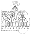
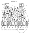
- Figures 4A to 7 show examples on how a network evolves as the number of the subscribers grows and as the user's requirements change. These scenarios also depict one way the phased delivery of scalability functionality could impact the evolution of network management in a company.
- Each network manager directly manages a number of operation controllers 31,33,35,37,39,41,43,45,47 , and 49 .
- the description and drawings refer to OPCs for simplification, but it is to be understood that the invention applies also to other element controllers.
- the OPCs are deployed as necessary at various sites in the Western and Eastern region.
- Figure 6A also shows that some OPCs are managed by two network managers, for reasons that will be explained later.
- OPCs 35 and 37 are monitored by both network manager 30 and network manager 40
- OPCs 41 are monitored by network manager 40 in the Western region and network manager 60 in the Eastern region.
- NOC network operations center
- the explosive growth of the network of Figure 4A has led NP to realize that a network operations center (NOC) 70 need to be created for monitoring the entire network via direct connections 71 , as shown in Figure 4B for the second phase of growth (NOC is also a NM).
- NOC network operations center
- the regional network managers 30, 40 and 60 still exist for the day-to-day running of the network, while the NOC 70 is primarily used for off-hours support and demos to customers.
- NP realizes that the number of connections per OPC must be increased from two to four for allowing more connections per OPC and more OPCs per network manager, for some controllers, such as OPC 35, 37 and 41 which each need three connections to them.
- the site for NOC 70 can be a dangerous place, subject to earthquakes, volcanoes, power outages and crime.
- NP is concerned about survivability of the network and has built an alternative NOC 80 at a different site, to take over in disaster scenarios, as shown in Figure 4C.
- the alternative NOC 80 can be used to off-load NOC 70 during peak demand and holidays.
- provision of direct connections 81 to the OPCs exhausts the current maximum number of connections (four) for OPCs 35, 37 , and 41 .
- indirect element controller management allows a reduction in the number of connections used at the sub-network controlling devices, as seen in Figure 5A.
- the number of direct connections in group 51 and group 53 has been reduced from four to three by implementation of indirect connections 63 and 65 .
- a federated connection 61 has been set between NM 30 and 40 . No changes have been made to the OPCs that each network manager directly manages, NM 30,40 and 60 see the same controllers as before indirect management.
- Next phase of growth provides for expanding the controllers managed by network manager 30 to include OPCs 37, 39 and 41 , namely all OPCs in the Western region, as shown in Figure 5B. This was done by increasing the number of indirect connections in group 63 from one to three. Similarly, the OPCs managed by NM 40 include now all of the OPCs in the Western region, by increasing the number of indirect connections in group 65 from one to three. By indirectly connecting to OPCs 31, 33 and 35 , more users have visibility of all of the NEs in the Western region.
- NOCs 70 and 80 are given a view of the entire network by federating each network operating center with the regional network managers 30, 40 and 60 , as shown in Figure 6A.
- Indirect connection 63 and 65 are configured as in the embodiment of Figure 5A.
- NOCs 70 and 80 do not directly manage any controllers, rather they manage all of the OPCs indirectly via the regional network managers. Implementing this is easy as it is simply a case of changing the existing direct connections to the OPCs, as shown in Figure 4C, into indirect connections.
- FIG. 6B A much cleaner picture of the connections in the network is shown in Figure 6B, which is Figure 6A with the indirect connections removed.
- the indirect connections are only logical connections, no surveillance or status information flows along these connections.
- NOCs 70 and 80 cannot indirectly manage the OPCs 41, 43, 45, 47, and 49 in the Eastern Region, and some form of direct management must be provided.
- One possible reconfiguration is shown in Figure 7, NM 60 with its direct connections is not shown for simplification and also because is not turned on. Controllers at 47 are now directly managed by NOC 70 , and controllers at 43, 45 and 49 are directly managed by NOC 80 .
- NOCs 70 and 80 have created a federated connection 78 between them so that they can indirectly manage the OPCs the other is directly managing.
- Self-healing requires a NM to seek out other NMs to federate to, or in the worst case, a network manager has to resort to directly managing the controller.
- Finding another network manager to federate to is the ideal self-healing process, because the healing process is quite short, and therefore configuring the network to try and take advantage of this is highly desirable.
- One way to facilitate this objective is to have multiple network managers directly managing each OPC, so that federated network managers can quickly re-establish indirect connections. Eliminating single-points of failure is the primary goal.
- the network managers directly managing each OPC should be connected via different routes and should be geographically separated to eliminate the chance of environmental problems disabling both network managers simultaneously.
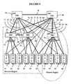
- NP decided to increase the responsibility of the NOC workstations so that they share in the management of the controllers, as shown in Figure 9.
- network manager 70 could monitor OPCs 49 via federated connection 76 to network manager 60 , and the respective direct connection of group 55 , or via federated connection 78 to network manager 80 , and direct connection 88 . Both routes directly manage OPCs 49 .
- each regional network manager is wisely split in the configuration of Figure 9, so that the effort is shared when a regional network manager is off-line.
- network manager 70 were indirectly managing OPC 49 via network manager 60 and network manager 60 lost power
- network manager 70 would switch to indirect management via network manager 80 .
- network manager 80 were indirectly managing OPC 41 via network manager 60 , and network manager 60 lost power
- network manager 80 would switch to indirect management via network manager 40 .
- network manager 70 were indirectly managing OPC 45 via network manager 80 , the failure of network manager 60 would have no impact.
- NP wishes to enter a joint alliance with a long-distance provider LD, they must share management of a set of OPCs, let's say OPCs 41 . Most probably, NP does not want LD to determine how the remaining of the network is managed. Conversely, LD does not want NP to determine how its network is managed.
- the solution is to configure separate networks to terminate at the OPC, and each company to configure their network manager to directly manage the shared OPCs. This does not change the NP configuration of the network of Figure 9 at all, except the number of free connections on each of the shared OPCs is reduced.
- Figure 10 shows the main components of a NM and an element controller relevant to this invention.
- Network manager 30 shown in Figure 10 is a workstation which provides nodal and sub-network OAM&P capabilities through a single view of transport and access nodes and directly manages a plurality of NEs that are connected to OPC 41 .
- NM 30 may also indirectly manage a plurality of OPCs and can act as a client or server for other NMs.
- NM 30 provides a graphical surveillance user interface (GUI) tool including a plurality of graphical network browsers (GNB) 12 and a configuration GUI named the graphical network editor (GNE) 14 .
- GUI graphical surveillance user interface
- GNE graphical network editor
- Network managers are configured by the user via GNE 14 to directly or indirectly manage element controllers on a per span basis. Provisioning what controllers the network manager is interested in by specifying their IP address, is done in the GNE 14 as usual. The fundamental difference is that the operator may now select the preferred management path, direct or indirect. To this end, GNE 14 selects the element controller and the preferred management path, i.e. direct or indirect.
- An indirect server manager component (ISM) 34 and an indirect client manager component (ICM) 36 are the core of the scalability and survivability solution. These components are integrated into the existing network manager collector process and provide the ability to service incoming requests from other network managers as an indirect server, and to similarly establish connections to other network managers as indirect clients.
- ISM component 34 provides a mechanism to service indirect management requests from other network manager workstations. This is accomplished by creating a TCP/IP server at a well known port for processing the incoming requests.
- NM 30 as a directly managing server and a client NM is provided over a federation network interface (NNI) 32 .
- NNI federation network interface
- the indirect server 34 waits for requests from the client NM for the specific OPC/MOA entities that the requester is interested in. Only requests for controllers that are currently being managed via a direct connection to the OPC or MOA such as OPC 41 will be considered by ISM 34.
- This negotiation is complete, information flow for the controller pair is transmitted from ISM 34 to the indirect client NM. Only one TCP/IP connection is maintained per communicating network managers.
- This information includes core network element information, such as name identifiers, rate, type and support information, existing active alarms, and asynchronously delivery alarm state transitions, performance monitoring support information, sub-network configuration data, and network element connectivity or association status.
- ICM 36 The role of ICM 36 is to find a path to a controller if the management path is specified by GNE 14 as indirect. It does this by first querying that OPC for the list of currently connected network managers, then attempting to register indirectly through another network manager. If there are no direct managers available, ICM 36 will attempt to reluctantly promote itself to direct management of that controller.
- ICM 36 When presented with a choice of two or more possible routes for indirect management, ICM 36 will choose a preferred route according to a preference algorithm, if it is available.
- the preference algorithm uses an indirect access database (IAD) 38 , and performs for example the following operations:
- This strategy allows for an additional level of control over indirect management, allowing optimal network paths (where there is more bandwidth, for example) to be established first, if available.
- IAD 38 is also consulted by ICM 36 before allowing access to an indirect manager client.
- This database comprises of a list of IP addresses or sub-networks that requests will or will not be accepted from. This is used to facilitate the creation of independent federations which do not share management information or interact with each other. It is also used to ensure a predictable environment during software testing.
- the database 38 is modifiable using a simple configuration tool accessible from the existing administration tools.
- a network data cache may be used in another embodiment of the invention for managing and storing data previously shared by all GNB's into a single cache entity, available for reading by all network manager processes.
- NDC is used to write various data in a shared area to be accessed in a read-only fashion by all other network manager processes.
- the goal of NDC is to achieve an order of magnitude savings as compared to the existing GNB 12 and GNE 14 process under similar loaded conditions, thus minimizing or eliminating the requirement for additional hardware to achieve the engineering limits.
- a component of the architecture according to the invention is implemented in the collector name server (CNS) 46 component provided at each OPC/MOA workstation.
- CNS 46 whose interface is implemented through the existing regulation browser (REGB) process on the OPC, provides a mechanism to query the OPC server for the existing directly connected NM workstations, necessary for enabling ICM 36 to select a path for indirect management.
- REGB existing regulation browser
- access to the NE and OPC/MOA user interface is accomplished by using the primary network manager collector to controller interface to add entries in the appropriate control files on the controller, which then allows the network manager unauthenticated remote execution of selected processes, if a concurrent entry for the invoking client UNIX userid is present on the controller.
- each indirect connection accounts for the equivalent of two directly managed element controller spans. This parameter is enforced and has been deduced by engineering studies on the existing architecture.
- An interface is provided by ISM 36 , to manage and keep track of these indirect connections for the purpose of engineering the entire NM collector process. Specifically, because of the possibility of a failure of one or more indirectly managing workstations causing the client to attempt direct connections to the controller and potentially well exceed its maximum number of direct connections, this number in conjunction with the current number of primary and backup direct connections may be used to enforce engineering limits in the software.
- controller list dialogue can also be substantially modified to accommodate the now larger volume of controllers, as well as reflect the routing decisions being made by the network manager, such as IP address of network manager serving an indirect connection, indirect or direct preferred state, and the current actual management state of each controller. This information should also be visible to GNB users in a read only fashion.
- T1 or equivalent bandwidth as a minimal requirement to sustain acceptable performance between federated network managers.
- the entire network bandwidth can be engineered to account for shifts in management responsibility that will happen when survivability aspects are considered. Any extra bandwidth required to maintain acceptable performance when shifts in management happen will largely depend on how the federation is setup and how many spans are being managed concurrently across the federated connections.
- Figure 11 illustrates how an indirect connection is established in the network of Figure 9.
- NM 70 requests communication with OPC 41 as shown in step 100.
- NM 70 queries OPC 41 via CNS 46 regarding the NM directly connected to this OPC, in step 110. If a plurality of direct NMs is found, such as NM 40 and NM 60 in step 120, a preference algorithm selects a preferred direct NM in steps 130-150.
- NM 70 When specifying a preferred direct connection, an attempt is made to register directly with the element controller 41 as usual. If both NM 40 and NM 60 failed, or none of NM 40 and NM 60 directly manage OPC 41 , as illustrated along the NO branch in step 120 , NM 70 would negotiate a self-promotion with the element controller to directly manage it, as shown in step 220 . Information now flows between NM 70 and OPC 41 , step 230 , and other network managers could then indirectly manage the element controller 41 via this promoted network manager.
- NM 70 will attempt to restore back to indirect management at the first available opportunity, as shown by the timer in step 240 .
- the preference algorithm initiated in step 130 is designed to take into account the network architecture and also the client's demands.
- steps 140 and 150 NM 70 determines which one of NM 60 and NM 40 has a preferred direct connection to OPC 41 and establishes a management path to this preferred NM. If a preferred direct connection is not available, as shown by branch 'NO' of block 150 , NM 70 determines which one of NM 60 and 40 has a preferred reluctantly promoted connection to OPC 41 , as shown in steps 200 and 210 .
- Step 160 shows the flow of information between NM 70 and OPC 41, once a management path has been established in steps 130, 140, 150, 200, and 210.
- Any changes in management path initiated under the control of the federation will attempt to happen transparent to the GNB user, in other words without indicating a loss of connectivity for those network elements affected (normally done by turning the affected icons blue). This is called a no-blue switch.
- a direct benefit of scalability is the inherent survivability that comes from the distributed management of the network.
- Survivability is implemented using a revertive N:1 strategy that allows multiple network managers in the federation to maintain management of element controllers which can no longer be managed by another network manager for reasons such as workstation or network outages.
- This is accomplished by an indirect client, such as NM 70 in the example of Figure 9, seeking out another server, such as NM 60 in the federation, if its current server becomes unavailable, or if a controller becomes unavailable from the point of view of the current directly managing server.
- the NEs operate as in the case of establishing an indirect connection, shown in Figure 11.
- NM 40 will be selected by the preference algorithm in step 130 .
- FIG. 12 is flow-chart showing the operation of the network to re-establish a direct connection.
- NM 70 requests a direct connection with OPC 47 . If the registration to this OPC is full, i.e. the element controller already serves four NMs, as shown by the 'YES' branch in step 310 , the query is repeated at regular intervals of time, shown in step 320, until OPC 47 becomes available, shown by branch 'NO'. In this case, information flows between NM 70 and OPC 47 along direct connection 77 , as illustrated in step 330 .
- a network manager preferred management route is direct, and it cannot establish a direct connection because the controller registration is full and all other connections are preferred direct, it will not demote itself to indirect. It is the responsibility of the federation manager to configure the network with no more than the maximum number of direct connections supported for that controller.
- IP connectivity is no longer required between the network manager and the element controller it manages indirectly.
- IP connectivity is required to set up indirect management in the first place.
- IP connectivity is also required for on-demand functionality such as remote login, PM query, remote inventory, shelf level graphics, and electronic software delivery. For increased survivability, IP connectivity is required to allow the network manager to directly manage the element controller if for some reason it cannot find another network manager directly managing the specific device.
- NM 80 will attempt to reluctantly promote itself to direct management of OPC 33 if there are any connections available.
- ICM 38 continues after recovery by continuously attempting to recover a connection via an indirect path. When a route becomes available, a switch over is completed without presenting a loss of connectivity to depending applications. By always attempting a return to this steady state, some level of control over communicating entities is preserved.
- this switch over may also impact other workstations in the federation, who may be managing indirectly via the reluctantly promoted path.
- the switch over is mandatory, although all attempts will be made to re-establish routes without presenting a loss of connectivity to the application.
- NM 70 and NM 80 will be notified.
- a client, say NM 80 will then attempt to connect to OPC/MOA 33 and establish a connection via an alternate route, for example through directly connected NM 70 , hence surviving a connectivity problem due to a network outage that only affected its current indirect server. If there is no TCP/IP connectivity between the indirect client workstation and the controller (i.e. the controller is down, or invisible due to the same network outage), it will continue to attempt indirect connections until a path becomes available.
- Ethernet interfaces are not supported; if a workstation is part of multiple sub-networks due to more than one LAN interface, the preferred path will only be discovered if this is true because of the first or default interface, as specified in the IP host map.
- the architecture allows for the future evolution of the messaging interface between the NM and the controller which will allow the indirect server to communicate addressing information about indirect clients to the controller, allowing the indirect clients to make login requests directly to the OPC or MOA.
- a tool could be provided to remotely retrieve the preferred directly managed spans of any network manager in the federation and apply any or all of those spans as preferred indirect in the local network manager's domain.
- the load on each NM is defined by the number of controllers it directly manages. This is configured manually by the user in the GNE and can be re-defined at any time, so that all NM directly manage their fair share of OPCs.
- the load is distributed randomly based on which network manager is the first to claim a direct connection to each OPC, influenced by the network topology and the distribution of the network managers within that topology. It is anticipated that given the random nature of this algorithm, a uniform distribution will be achieved.
Landscapes
- Engineering & Computer Science (AREA)
- Computer Networks & Wireless Communication (AREA)
- Signal Processing (AREA)
- Computer And Data Communications (AREA)
- Data Exchanges In Wide-Area Networks (AREA)
Description
Claims (21)
- A method of federating first and second communications networks comprising a respective plurality of element controllers ,ECs, logically connected to a corresponding network manager, NM, over respective direct management paths for direct management of the EC's by the corresponding NM, characterised in that the method comprises the steps of:a) selecting, from at least two management paths, a preferred management path between an element controller, EC2, of the second network and a network manager , NM1, of the first network; andb) establishing a logical connection between the NM1 and the EC2 over the selected preferred management path, to enable management of the EC2 by the NM1.
- A method as claimed in claim 1, wherein the at least two management paths comprise one or more of: an indirect management path via a federated connection between the NM1 and a network manager, NM2, of the second network logically connected to the EC2 over a direct management path; and a reluctantly promoted direct management path between the NM1 and the EC2.
- A method as claimed in claim 2, wherein the step of selecting a preferred management path comprises the steps of, from the NM1:a) querying the EC2 to obtain information identifying the NM2;b) determining if the NM2 is directly managing the EC2;c) if the NM2 is directly managing the EC2, selecting the preferred management path as the indirect management path via the federated connection between the NM1 and the NM2;d) if the NM2 is not directly managing the EC2:i) assuming a reluctantly promoted state at the NM1 to enable direct management of the EC2 by the NM1; andii) selecting the preferred management path as the reluctantly promoted direct management path between the NM1 and the EC2.
- A method as claimed in claim 3, further comprising, if the NM2 is not directly managing the EC2, the step of periodically attempting to demote the NM1 from the reluctantly promoted state.
- A method as claimed in claim 4, wherein the step of periodically attempting to demote the NM1 comprises the steps of:a) periodically determining if the NM2 has recovered direct management of the EC2; andii) when the NM2 has recovered direct management of the EC2:ii) demoting the reluctantly promoted state of the NM1; andii) selecting the preferred management path as the indirect management path via the federated connection between the NM1 and the NM2.
- A method as claimed in claim 1, wherein the step of querying the EC comprises:a) sending a query message to the EC2, and receiving a response message from the EC2 containing information identifying each network manager logically connected to the EC2 over a direct management path; andb) selecting the information identifying the NM2 from among the information identifying each network manager logically connected to the EC2 over a direct management path.
- A method as claimed in claim 3, wherein the step of determining if the NM2 is available for communication with the EC2 comprises the steps of:a) sending a connection request message to the NM2 and waiting for a response message from the MN2;b) if the response message is received from the MN2, determining that the NM2 is available; andc) otherwise, determining that the NM2 is not available.
- A method as claimed in claim 10, wherein, when the preferred management path is the indirect management path via a federated connection, the step of establishing a logical connection over the preferred management path comprises:a) establishing a federated connection between the NM1 and the NM2, the NM1 acting as an indirect client for the NM2, and the NM2 acting as an indirect server for the NM1; andb) establishing a logical connection between the NM1 and the EC2 through the NM2 using the federated connection.
- A scalable communication network having a plurality of element controllers, ECs, adapted to control operations of a respective plurality of network elements, and two or more network managers, NMs, adapted for managing each of the element controllers, ECs, characterised in that the network comprises:a) a first network manager, NM1, logically connected to a first element controller, EC1, via a direct management path for direct management of the EC1 by the NM1; andb) a second network manager, NM2, adapted to:i) select, from at least two management paths, a preferred management path between the NM2 and the EC1; andii) establish a logical connection between the NM2 and the EC1 over the selected preferred management path to enable management of the EC1 by the NM2.
- A scalable communication network as claimed in claim 9, wherein the at least two management paths comprise one or more of: an indirect management path via a federated connection between the NM2 and the NM1; and a reluctantly promoted direct management path between the NM2 and the EC1.
- A scalable communication network as claimed in claim 10, wherein the first network manager, NM1, comprises an indirect server manger, ISM, component adapted to enable a federated connection between the first network manager, NM1, and the second network manager, NM2.
- A scalable communication network as claimed in claim 11, wherein the indirect server manger, ISM component is further adapted to enable a logical connection between the first element controller, EC1, and the second network manager, NM2 through the federated connection.
- A scalable communication network as claimed in claim 10, wherein the second network manager, NM2, comprises an indirect client manager, ICM, component adapted to enable management of the first element controller, EC1, using the selected preferred management path.
- A scalable communication network as claimed in claim 13, wherein the ICM component is adapted to dynamically select the preferred management path by:a) querying the EC1 to obtain information identifying the NM1 logically connected to the EC1 via a direct management path;b) determining if the NM1 is directly managing the EC1;c) if the NM1 is directly managing the EC1, selecting the preferred management path as the indirect management path via the federated connection between the NM2 and the NM1;d) if the NM1 is not directly managing the EC1:i) assuming a reluctantly promoted state to enable direct management of the EC1 by the NM2; andii) selecting the preferred management path as the reluctantly promoted direct management path between the NM2 and the EC1.
- A scalable communication network as claimed in claim 14, wherein, if the NM1 is not directly managing the EC1, the ICM component is adapted to periodically attempt to demote the NM2 from the reluctantly promoted state.
- A scalable communication network as claimed in claim 15, wherein the ICM component is adapted to periodically attempt to demote the NM2 by:a) periodically determining if the NM1 has recovered direct management of the EC; andb) when the NM1 has recovered direct management of the EC:i) demoting the reluctantly promoted state of the NM2; andii) selecting the preferred management path as the indirect management path via the federated connection between the NM2 and the NM1.
- A scalable communication network as claimed in claim 9, wherein each element controller comprises a respective collector name server including information identifying each network manager to which the element controller is logically connected over a direct management path.
- A scalable communication network as claimed in claim 17, wherein the collector name server is responsive to a query from the NM1 to send a response message to the NM1 containing the information identifying each network manager to which the element controller is logically connected over a direct management path.
- A scalable communication network as claimed in claim 19, wherein each network manager, NM, comprises a respective indirect access database, IAD, including information respecting devices to which the network manager can logically connect.
- A scalable communication network as claimed in claim 19, wherein the IAD further comprises information identifying other network managers from which connection requests will be accepted to permit indirect management of any element controllers directly managed by the respective network manager, NM.
- A scalable communication network as claimed in claim 20, wherein the IAD further comprises a list of paths available for selection as a preferred management path to enable management of an element controller.
Applications Claiming Priority (3)
| Application Number | Priority Date | Filing Date | Title |
|---|---|---|---|
| US08/878,636 US6266694B1 (en) | 1997-06-19 | 1997-06-19 | Architecture for network manager |
| US878636 | 1997-06-19 | ||
| PCT/CA1998/000543 WO1998059462A1 (en) | 1997-06-19 | 1998-06-03 | Architecture for network manager |
Publications (2)
| Publication Number | Publication Date |
|---|---|
| EP0990328A1 EP0990328A1 (en) | 2000-04-05 |
| EP0990328B1 true EP0990328B1 (en) | 2005-03-23 |
Family
ID=25372473
Family Applications (1)
| Application Number | Title | Priority Date | Filing Date |
|---|---|---|---|
| EP98925351A Expired - Lifetime EP0990328B1 (en) | 1997-06-19 | 1998-06-03 | Architecture for network manager |
Country Status (6)
| Country | Link |
|---|---|
| US (1) | US6266694B1 (en) |
| EP (1) | EP0990328B1 (en) |
| JP (1) | JP3354160B2 (en) |
| CA (1) | CA2287189A1 (en) |
| DE (1) | DE69829476T2 (en) |
| WO (1) | WO1998059462A1 (en) |
Families Citing this family (48)
| Publication number | Priority date | Publication date | Assignee | Title |
|---|---|---|---|---|
| US7383341B1 (en) * | 1996-10-15 | 2008-06-03 | Kabushiki Kaisha Toshiba | Data transfer control device, relay device and control device suitable for home network environment |
| US7047300B1 (en) * | 1998-02-10 | 2006-05-16 | Sprint Communications Company L.P. | Survivable and scalable data system and method for computer networks |
| US7269475B1 (en) * | 1998-03-02 | 2007-09-11 | Xerox Corporation | Distributed control system with global contraints for controlling object motion with smart matter |
| US8010627B1 (en) | 1998-09-25 | 2011-08-30 | Sprint Communications Company L.P. | Virtual content publishing system |
| JP2000307603A (en) * | 1999-04-23 | 2000-11-02 | Matsushita Electric Ind Co Ltd | Network monitoring method and apparatus |
| US6986137B1 (en) * | 1999-09-28 | 2006-01-10 | International Business Machines Corporation | Method, system and program products for managing logical processors of a computing environment |
| US6519660B1 (en) * | 1999-09-28 | 2003-02-11 | International Business Machines Corporation | Method, system and program products for determining I/O configuration entropy |
| DE19949531A1 (en) * | 1999-10-14 | 2001-04-19 | Deutsche Telekom Ag | Device for controlling a telecommunication system |
| IL133083A (en) * | 1999-11-22 | 2004-02-08 | Eci Telecom Ltd | Method and system for management of network domains |
| WO2001057685A1 (en) * | 2000-01-31 | 2001-08-09 | Fujitsu Limited | Server determining method and device |
| US7194533B1 (en) * | 2000-04-28 | 2007-03-20 | Microsoft Corporation | System and method for editing active measurements in a client management tool |
| US7051098B2 (en) * | 2000-05-25 | 2006-05-23 | United States Of America As Represented By The Secretary Of The Navy | System for monitoring and reporting performance of hosts and applications and selectively configuring applications in a resource managed system |
| JP2002033767A (en) * | 2000-07-18 | 2002-01-31 | Fujitsu Ltd | Network management system |
| US7266084B2 (en) | 2000-12-29 | 2007-09-04 | Wireless Lan Systems Oy | Method and arrangement for maintaining and updating network element configuration in an xDSL network, and an xDSL network element |
| US6941358B1 (en) | 2001-12-21 | 2005-09-06 | Networks Associates Technology, Inc. | Enterprise interface for network analysis reporting |
| US6892227B1 (en) | 2001-12-21 | 2005-05-10 | Networks Associates Technology, Inc. | Enterprise network analyzer host controller/zone controller interface system and method |
| US7483861B1 (en) | 2001-12-21 | 2009-01-27 | Mcafee, Inc. | System, method and computer program product for a network analyzer business model |
| US6754705B2 (en) | 2001-12-21 | 2004-06-22 | Networks Associates Technology, Inc. | Enterprise network analyzer architecture framework |
| US7154857B1 (en) | 2001-12-21 | 2006-12-26 | Mcafee, Inc. | Enterprise network analyzer zone controller system and method |
| US7062783B1 (en) | 2001-12-21 | 2006-06-13 | Mcafee, Inc. | Comprehensive enterprise network analyzer, scanner and intrusion detection framework |
| US6789117B1 (en) | 2001-12-21 | 2004-09-07 | Networks Associates Technology, Inc. | Enterprise network analyzer host controller/agent interface system and method |
| US6714513B1 (en) | 2001-12-21 | 2004-03-30 | Networks Associates Technology, Inc. | Enterprise network analyzer agent system and method |
| JP2003259469A (en) * | 2002-02-28 | 2003-09-12 | Mitsubishi Electric Corp | Wide-area management method and system for water supply facility |
| EP1349315A1 (en) * | 2002-03-27 | 2003-10-01 | BRITISH TELECOMMUNICATIONS public limited company | Policy based system management |
| US20040027384A1 (en) * | 2002-08-12 | 2004-02-12 | Gilbert Levesque | End-to-end tracing of wavelength parameters in a wavelength division multiplexing span of a fiber optic network |
| CN1283079C (en) * | 2003-02-20 | 2006-11-01 | 华为技术有限公司 | IP network service quality assurance method and system |
| US20060031449A1 (en) * | 2004-07-01 | 2006-02-09 | Mika Hallamaa | Selection of management method |
| US8073960B2 (en) * | 2004-07-01 | 2011-12-06 | Nokia Corporation | Arranging management operations in management system |
| US8392545B2 (en) * | 2004-07-01 | 2013-03-05 | Nokia Corporation | Device management system |
| WO2006026753A2 (en) * | 2004-09-02 | 2006-03-09 | General Dynamics C4 Systems, Inc. | Distributed networking agent (dna) and methods of making and using the same |
| US7302611B2 (en) * | 2004-09-13 | 2007-11-27 | Avaya Technology Corp. | Distributed expert system for automated problem resolution in a communication system |
| JP4589180B2 (en) * | 2005-06-14 | 2010-12-01 | 株式会社日立製作所 | Switching node |
| US20060288009A1 (en) * | 2005-06-20 | 2006-12-21 | Tobid Pieper | Method and apparatus for restricting access to an electronic product release within an electronic software delivery system |
| US8271387B2 (en) * | 2005-06-20 | 2012-09-18 | Intraware, Inc. | Method and apparatus for providing limited access to data objects or files within an electronic software delivery and management system |
| GB2431067B (en) | 2005-10-07 | 2008-05-07 | Cramer Systems Ltd | Telecommunications service management |
| GB2432992B (en) * | 2005-11-18 | 2008-09-10 | Cramer Systems Ltd | Network planning |
| GB2433675B (en) * | 2005-12-22 | 2008-05-07 | Cramer Systems Ltd | Communications circuit design |
| US7903585B2 (en) * | 2006-02-15 | 2011-03-08 | Cisco Technology, Inc. | Topology discovery of a private network |
| GB2435362B (en) * | 2006-02-20 | 2008-11-26 | Cramer Systems Ltd | Method of configuring devices in a telecommunications network |
| JP2008113955A (en) * | 2006-11-07 | 2008-05-22 | Aruze Corp | Game device |
| US7996510B2 (en) * | 2007-09-28 | 2011-08-09 | Intel Corporation | Virtual clustering for scalable network control and management |
| US8954562B2 (en) * | 2007-09-28 | 2015-02-10 | Intel Corporation | Entropy-based (self-organizing) stability management |
| JP2009276999A (en) * | 2008-05-14 | 2009-11-26 | Canon Inc | Information collection apparatus and its control method, network apparatus and its control method, and program |
| US20100110977A1 (en) * | 2008-11-04 | 2010-05-06 | Broadcom Corporation | Management unit network for managing a plurality of multiservice communication devices |
| US8966017B2 (en) | 2009-07-09 | 2015-02-24 | Novell, Inc. | Techniques for cloud control and management |
| US9049104B2 (en) * | 2011-07-19 | 2015-06-02 | Telefonaktiebolaget L M Ericsson (Publ) | Coordination of M2M device operation by M2M device managers in a LAN |
| JP6760899B2 (en) * | 2017-08-04 | 2020-09-23 | 日本電信電話株式会社 | Network service management device, network service management method, and network service management program |
| US11516302B2 (en) * | 2020-06-16 | 2022-11-29 | Hewlett Packard Enterprise Development Lp | Network service discovery |
Family Cites Families (20)
| Publication number | Priority date | Publication date | Assignee | Title |
|---|---|---|---|---|
| JPH0634537B2 (en) * | 1987-01-12 | 1994-05-02 | 富士通株式会社 | Inter-device communication control method |
| US5021949A (en) * | 1988-02-29 | 1991-06-04 | International Business Machines Corporation | Method and apparatus for linking an SNA host to a remote SNA host over a packet switched communications network |
| JP2560510B2 (en) * | 1990-03-06 | 1996-12-04 | 日本電気株式会社 | Network management manager switching method |
| US5261044A (en) | 1990-09-17 | 1993-11-09 | Cabletron Systems, Inc. | Network management system using multifunction icons for information display |
| US5375199A (en) | 1991-06-04 | 1994-12-20 | Digital Equipment Corporation | System monitoring method and device including a graphical user interface to view and manipulate system information |
| DE4133385A1 (en) * | 1991-10-09 | 1993-04-15 | Philips Patentverwaltung | HIERARCHICAL NETWORK MANAGEMENT SYSTEM |
| JPH06236337A (en) * | 1993-02-08 | 1994-08-23 | Honda Motor Co Ltd | Computer system management method |
| JPH0721135A (en) | 1993-07-02 | 1995-01-24 | Fujitsu Ltd | Data processing system with redundant monitoring function |
| CA2145921A1 (en) * | 1994-05-10 | 1995-11-11 | Vijay Pochampalli Kumar | Method and apparatus for executing a distributed algorithm or service on a simple network management protocol based computer network |
| JP3521955B2 (en) * | 1994-06-14 | 2004-04-26 | 株式会社日立製作所 | Hierarchical network management system |
| US5737526A (en) * | 1994-12-30 | 1998-04-07 | Cisco Systems | Network having at least two routers, each having conditional filter so one of two transmits given frame and each transmits different frames, providing connection to a subnetwork |
| US5742762A (en) * | 1995-05-19 | 1998-04-21 | Telogy Networks, Inc. | Network management gateway |
| US5774669A (en) * | 1995-07-28 | 1998-06-30 | The United States Of America As Represented By The Administrator Of The National Aeronautics And Space Administration | Scalable hierarchical network management system for displaying network information in three dimensions |
| JP3271493B2 (en) * | 1995-09-26 | 2002-04-02 | ヤマハ株式会社 | Network and data transmission method |
| US5758083A (en) * | 1995-10-30 | 1998-05-26 | Sun Microsystems, Inc. | Method and system for sharing information between network managers |
| US5828847A (en) * | 1996-04-19 | 1998-10-27 | Storage Technology Corporation | Dynamic server switching for maximum server availability and load balancing |
| US5768501A (en) * | 1996-05-28 | 1998-06-16 | Cabletron Systems | Method and apparatus for inter-domain alarm correlation |
| US5913036A (en) * | 1996-06-28 | 1999-06-15 | Mci Communications Corporation | Raw performance monitoring correlated problem alert signals |
| US5872931A (en) * | 1996-08-13 | 1999-02-16 | Veritas Software, Corp. | Management agent automatically executes corrective scripts in accordance with occurrences of specified events regardless of conditions of management interface and management engine |
| US5768522A (en) * | 1997-03-06 | 1998-06-16 | Mci Communications Corporation | System and method for a multiple state, multiple case counter |
-
1997
- 1997-06-19 US US08/878,636 patent/US6266694B1/en not_active Expired - Lifetime
-
1998
- 1998-06-03 JP JP50344399A patent/JP3354160B2/en not_active Expired - Fee Related
- 1998-06-03 DE DE69829476T patent/DE69829476T2/en not_active Expired - Fee Related
- 1998-06-03 CA CA002287189A patent/CA2287189A1/en not_active Abandoned
- 1998-06-03 EP EP98925351A patent/EP0990328B1/en not_active Expired - Lifetime
- 1998-06-03 WO PCT/CA1998/000543 patent/WO1998059462A1/en not_active Ceased
Also Published As
| Publication number | Publication date |
|---|---|
| CA2287189A1 (en) | 1998-12-30 |
| DE69829476T2 (en) | 2005-09-08 |
| EP0990328A1 (en) | 2000-04-05 |
| JP3354160B2 (en) | 2002-12-09 |
| WO1998059462A1 (en) | 1998-12-30 |
| JP2000513191A (en) | 2000-10-03 |
| DE69829476D1 (en) | 2005-04-28 |
| US6266694B1 (en) | 2001-07-24 |
Similar Documents
| Publication | Publication Date | Title |
|---|---|---|
| US6266694B1 (en) | Architecture for network manager | |
| US9806983B2 (en) | System and method for control flow management in software defined networks | |
| EP1810447B1 (en) | Method, system and program product for automated topology formation in dynamic distributed environments | |
| US5812771A (en) | Distributed chassis agent for distributed network management | |
| EP2198579B1 (en) | Protocol for enabling dynamic and hierarchical interconnection of autonomous federations of enterprise service | |
| US7161935B2 (en) | Network fabric management via adjunct processor inter-fabric service link | |
| CA2406821C (en) | Switchable resource management in clustered computer system | |
| US20040064558A1 (en) | Resource distribution management method over inter-networks | |
| US20100142409A1 (en) | Self-Forming Network Management Topologies | |
| US20080069082A1 (en) | Service router for use with a service-oriented architecture environment | |
| EP1342344B1 (en) | Vpn device clustering using a network flow switch | |
| WO2002003203A2 (en) | Method and apparatus for controlling an extensible computing system | |
| JP2005521334A (en) | Network management system | |
| CA2217277A1 (en) | Automatic link establishment for distributed servers in atm networks | |
| US20040044754A1 (en) | Virtual local area network provisioning in bridged networks | |
| Aglan et al. | Reliability and scalability in SDN networks | |
| EP2575325A2 (en) | Method and system for distributing a network application among a plurality of network sites on a shared network | |
| CN114430415B (en) | An intelligent control system | |
| EP1712067B1 (en) | A method, apparatus and system of organizing servers | |
| EP3278519B1 (en) | Memory system management | |
| JP2000244496A (en) | Method and system for managing redundant configuration in communication system | |
| CN121940379A (en) | IP address allocation method, device, equipment and medium for realizing load balancing in virtualized environment | |
| CN113132137A (en) | Multiple virtual network system for guaranteeing communication and implementation method | |
| Sharma | Programmable Ethernet Switch Networks and Their Applications | |
| Nilausen | APPN—The Control Point |
Legal Events
| Date | Code | Title | Description |
|---|---|---|---|
| PUAI | Public reference made under article 153(3) epc to a published international application that has entered the european phase |
Free format text: ORIGINAL CODE: 0009012 |
|
| 17P | Request for examination filed |
Effective date: 20000118 |
|
| AK | Designated contracting states |
Kind code of ref document: A1 Designated state(s): DE FR GB |
|
| RAP1 | Party data changed (applicant data changed or rights of an application transferred) |
Owner name: NORTEL NETWORKS LIMITED |
|
| 17Q | First examination report despatched |
Effective date: 20011127 |
|
| RAP1 | Party data changed (applicant data changed or rights of an application transferred) |
Owner name: NORTEL NETWORKS LIMITED |
|
| GRAP | Despatch of communication of intention to grant a patent |
Free format text: ORIGINAL CODE: EPIDOSNIGR1 |
|
| GRAS | Grant fee paid |
Free format text: ORIGINAL CODE: EPIDOSNIGR3 |
|
| GRAA | (expected) grant |
Free format text: ORIGINAL CODE: 0009210 |
|
| AK | Designated contracting states |
Kind code of ref document: B1 Designated state(s): DE FR GB |
|
| REG | Reference to a national code |
Ref country code: GB Ref legal event code: FG4D |
|
| REF | Corresponds to: |
Ref document number: 69829476 Country of ref document: DE Date of ref document: 20050428 Kind code of ref document: P |
|
| PG25 | Lapsed in a contracting state [announced via postgrant information from national office to epo] |
Ref country code: GB Free format text: LAPSE BECAUSE OF NON-PAYMENT OF DUE FEES Effective date: 20050623 |
|
| PG25 | Lapsed in a contracting state [announced via postgrant information from national office to epo] |
Ref country code: DE Free format text: LAPSE BECAUSE OF NON-PAYMENT OF DUE FEES Effective date: 20060103 |
|
| PLBE | No opposition filed within time limit |
Free format text: ORIGINAL CODE: 0009261 |
|
| STAA | Information on the status of an ep patent application or granted ep patent |
Free format text: STATUS: NO OPPOSITION FILED WITHIN TIME LIMIT |
|
| ET | Fr: translation filed | ||
| GBPC | Gb: european patent ceased through non-payment of renewal fee |
Effective date: 20050623 |
|
| 26N | No opposition filed |
Effective date: 20051227 |
|
| REG | Reference to a national code |
Ref country code: FR Ref legal event code: ST Effective date: 20080229 |
|
| PG25 | Lapsed in a contracting state [announced via postgrant information from national office to epo] |
Ref country code: FR Free format text: LAPSE BECAUSE OF NON-PAYMENT OF DUE FEES Effective date: 20050630 |