EP0989473A2 - Induction heating type fixing device and method of producing an induced current generating member therefor - Google Patents
Induction heating type fixing device and method of producing an induced current generating member therefor Download PDFInfo
- Publication number
- EP0989473A2 EP0989473A2 EP99118084A EP99118084A EP0989473A2 EP 0989473 A2 EP0989473 A2 EP 0989473A2 EP 99118084 A EP99118084 A EP 99118084A EP 99118084 A EP99118084 A EP 99118084A EP 0989473 A2 EP0989473 A2 EP 0989473A2
- Authority
- EP
- European Patent Office
- Prior art keywords
- coil
- bobbin
- adhesion preventing
- preventing material
- replaced
- Prior art date
- Legal status (The legal status is an assumption and is not a legal conclusion. Google has not performed a legal analysis and makes no representation as to the accuracy of the status listed.)
- Granted
Links
- 230000006698 induction Effects 0.000 title claims abstract description 40
- 238000010438 heat treatment Methods 0.000 title claims abstract description 19
- 238000000034 method Methods 0.000 title claims description 70
- 239000000463 material Substances 0.000 claims abstract description 47
- 239000000853 adhesive Substances 0.000 claims abstract description 28
- 230000001070 adhesive effect Effects 0.000 claims abstract description 28
- 239000011810 insulating material Substances 0.000 claims abstract description 9
- 238000005470 impregnation Methods 0.000 claims abstract description 8
- 229920005989 resin Polymers 0.000 claims description 18
- 239000011347 resin Substances 0.000 claims description 18
- NBVXSUQYWXRMNV-UHFFFAOYSA-N fluoromethane Chemical compound FC NBVXSUQYWXRMNV-UHFFFAOYSA-N 0.000 claims description 12
- 229920002050 silicone resin Polymers 0.000 claims description 9
- 239000012790 adhesive layer Substances 0.000 claims description 6
- 238000004804 winding Methods 0.000 claims description 6
- 229910052731 fluorine Inorganic materials 0.000 claims description 5
- 239000011737 fluorine Substances 0.000 claims description 5
- 239000010410 layer Substances 0.000 claims description 5
- 239000002480 mineral oil Substances 0.000 claims description 5
- 235000010446 mineral oil Nutrition 0.000 claims description 5
- 239000004020 conductor Substances 0.000 claims description 4
- YCKRFDGAMUMZLT-UHFFFAOYSA-N Fluorine atom Chemical compound [F] YCKRFDGAMUMZLT-UHFFFAOYSA-N 0.000 claims 4
- 239000002210 silicon-based material Substances 0.000 claims 3
- 230000000694 effects Effects 0.000 description 8
- 238000001816 cooling Methods 0.000 description 6
- 229910052736 halogen Inorganic materials 0.000 description 3
- 150000002367 halogens Chemical class 0.000 description 3
- 238000004519 manufacturing process Methods 0.000 description 3
- XEEYBQQBJWHFJM-UHFFFAOYSA-N Iron Chemical compound [Fe] XEEYBQQBJWHFJM-UHFFFAOYSA-N 0.000 description 2
- 230000002500 effect on skin Effects 0.000 description 2
- 230000001747 exhibiting effect Effects 0.000 description 2
- 238000009413 insulation Methods 0.000 description 2
- 239000002184 metal Substances 0.000 description 2
- 229910052751 metal Inorganic materials 0.000 description 2
- 238000000465 moulding Methods 0.000 description 2
- RYGMFSIKBFXOCR-UHFFFAOYSA-N Copper Chemical compound [Cu] RYGMFSIKBFXOCR-UHFFFAOYSA-N 0.000 description 1
- PXGOKWXKJXAPGV-UHFFFAOYSA-N Fluorine Chemical compound FF PXGOKWXKJXAPGV-UHFFFAOYSA-N 0.000 description 1
- 239000004962 Polyamide-imide Substances 0.000 description 1
- 239000004642 Polyimide Substances 0.000 description 1
- 230000015556 catabolic process Effects 0.000 description 1
- 239000000919 ceramic Substances 0.000 description 1
- 239000003795 chemical substances by application Substances 0.000 description 1
- 229910052802 copper Inorganic materials 0.000 description 1
- 239000010949 copper Substances 0.000 description 1
- 238000000151 deposition Methods 0.000 description 1
- 238000005516 engineering process Methods 0.000 description 1
- 230000007613 environmental effect Effects 0.000 description 1
- 230000020169 heat generation Effects 0.000 description 1
- 229910052742 iron Inorganic materials 0.000 description 1
- 239000000696 magnetic material Substances 0.000 description 1
- 238000002844 melting Methods 0.000 description 1
- 230000008018 melting Effects 0.000 description 1
- 238000012986 modification Methods 0.000 description 1
- 230000004048 modification Effects 0.000 description 1
- 229920002312 polyamide-imide Polymers 0.000 description 1
- 229920001721 polyimide Polymers 0.000 description 1
- 229920001296 polysiloxane Polymers 0.000 description 1
- 238000003825 pressing Methods 0.000 description 1
- 230000005855 radiation Effects 0.000 description 1
- 229910001220 stainless steel Inorganic materials 0.000 description 1
- 239000010935 stainless steel Substances 0.000 description 1
Images

Classifications
-
- H—ELECTRICITY
- H05—ELECTRIC TECHNIQUES NOT OTHERWISE PROVIDED FOR
- H05B—ELECTRIC HEATING; ELECTRIC LIGHT SOURCES NOT OTHERWISE PROVIDED FOR; CIRCUIT ARRANGEMENTS FOR ELECTRIC LIGHT SOURCES, IN GENERAL
- H05B6/00—Heating by electric, magnetic or electromagnetic fields
- H05B6/02—Induction heating
- H05B6/10—Induction heating apparatus, other than furnaces, for specific applications
- H05B6/14—Tools, e.g. nozzles, rollers, calenders
- H05B6/145—Heated rollers
-
- G—PHYSICS
- G03—PHOTOGRAPHY; CINEMATOGRAPHY; ANALOGOUS TECHNIQUES USING WAVES OTHER THAN OPTICAL WAVES; ELECTROGRAPHY; HOLOGRAPHY
- G03G—ELECTROGRAPHY; ELECTROPHOTOGRAPHY; MAGNETOGRAPHY
- G03G15/00—Apparatus for electrographic processes using a charge pattern
- G03G15/20—Apparatus for electrographic processes using a charge pattern for fixing, e.g. by using heat
- G03G15/2003—Apparatus for electrographic processes using a charge pattern for fixing, e.g. by using heat using heat
- G03G15/2014—Apparatus for electrographic processes using a charge pattern for fixing, e.g. by using heat using heat using contact heat
- G03G15/2053—Structural details of heat elements, e.g. structure of roller or belt, eddy current, induction heating
-
- Y—GENERAL TAGGING OF NEW TECHNOLOGICAL DEVELOPMENTS; GENERAL TAGGING OF CROSS-SECTIONAL TECHNOLOGIES SPANNING OVER SEVERAL SECTIONS OF THE IPC; TECHNICAL SUBJECTS COVERED BY FORMER USPC CROSS-REFERENCE ART COLLECTIONS [XRACs] AND DIGESTS
- Y10—TECHNICAL SUBJECTS COVERED BY FORMER USPC
- Y10T—TECHNICAL SUBJECTS COVERED BY FORMER US CLASSIFICATION
- Y10T29/00—Metal working
- Y10T29/49—Method of mechanical manufacture
- Y10T29/49002—Electrical device making
- Y10T29/4902—Electromagnet, transformer or inductor
-
- Y—GENERAL TAGGING OF NEW TECHNOLOGICAL DEVELOPMENTS; GENERAL TAGGING OF CROSS-SECTIONAL TECHNOLOGIES SPANNING OVER SEVERAL SECTIONS OF THE IPC; TECHNICAL SUBJECTS COVERED BY FORMER USPC CROSS-REFERENCE ART COLLECTIONS [XRACs] AND DIGESTS
- Y10—TECHNICAL SUBJECTS COVERED BY FORMER USPC
- Y10T—TECHNICAL SUBJECTS COVERED BY FORMER US CLASSIFICATION
- Y10T29/00—Metal working
- Y10T29/49—Method of mechanical manufacture
- Y10T29/49002—Electrical device making
- Y10T29/4902—Electromagnet, transformer or inductor
- Y10T29/49071—Electromagnet, transformer or inductor by winding or coiling
Definitions
- the present invention relates to an induction heating type fixing device for an electrophotographic printer, facsimile apparatus, copier or similar image forming apparatus. More particularly, the present invention relates to a method of producing an induced current generating member for an induction heating type fixing device and exhibiting a desirable cooling effect. The present invention is applicable even to an induction coil for induction heating equipment in general.
- An image forming apparatus of the type using toner for forming a visible image includes a fixing device for fixing a toner image formed on a paper or similar recording medium.
- the fixing device includes a heat roller for melting the toner with heat and a press roller pressing the paper against the heat roller while conveying it.
- the heat roller has thereinside a heater usually implemented by a halogen lamp. The halogen lamp heats the heat roller to a preselected fixing temperature.
- the conventional heating system using a heater has the following problems left unsolved. It takes a substantial period of time for the heat roller to reach the fixing temperature (warm-up time), forcing the operator to simply wait without operating the apparatus at all. Another problem is that the heater implemented by a halogen lamp involves a substantial loss and therefore consumes substantial power. This is contrary to the current trend toward energy saving which is highlighted in the environment aspect. In such circumstances, there is an increasing demand for a fixing device featuring high efficiency and short warm-up time.
- a fixing method of the kind heating a heat roller formed of conductive metal with an eddy current derived from an electromagnetic wave is attracting increasing attention.
- This kind of method i.e., induction heating type fixing method drastically reduces the warm-up time and enhances efficiency and thereby contributes to the solution of environmental problems.
- One of conventional heat rollers for implementing this fixing method includes an induction coil wound spirally round a bobbin. When a high frequency current is caused to flow through the induction coil adjoining the inner periphery of the heat roller, a high frequency magnetic fie!d is formed and induces an eddy current in the heat roller. As a result, the heat roller itself is heated by Joule heat on the basis of the skin effect of the roller itself.
- the induction coil has customarily been formed of copper or similar highly conductive material.
- the problem with this kind of material is that a great high frequency current flowing through the induction coil causes the coil to heat despite high conductivity. This, coupled with the radiation heat of the heat roller, is apt to damage the insulation layer of the coil and bring about short-circuiting.
- a bobbin for wrapping the induction coil may be omitted in order to efficiently release heat output from the coil to the outside, as also proposed in the past.
- this kind of configuration in principle, enhances the coil cooling effect to a remarkable extent, it has heretofore been considered difficult to produce. Such a scheme has not been practiced with an induction coil for an induction heating type fixing device.
- a mold coil is also known in the art and customarily used in, e.g., a transformer.
- a mold coil is sufficiently short for a given outside diameter and can therefore be implemented by a resin molding.
- fluidity available with resin is too low to implement a molding.
- an induction heating type fixing device includes a body to be heated and formed of a conductive material, and an induced current generating member disposed in the body to be heated.
- the induced current generating member includes a hallow cylindrical body formed of a heat-resistant insulating material and forming the outermost layer, an adhesive layer, and an induction coil contacting the inner periphery of the adhesive layer.
- a method of producing an induced current generating member for an induction heating type fixing device includes the steps of winding a coil round a bobbin applied with an adhesion preventing material, adhering the coil with nonconductive adhesive by impregnation and inserting the coil into a hollow cylindrical body, and adhering the coil to the hollow cylindrical body and pulling out the bobbin.
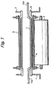
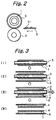
- the fixing device includes a press roller 2 and a heat roller 3 pressed against each other.
- the press roller 2 and heat roller 3 are rotatable counterclockwise and clockwise, respectively, as seen in FIG. 2.
- a gear, not shown, is mounted on one axial end of the heat roller 3 and held in mesh with a drive gear not shown.
- the drive gear causes the heat roller 3 to rotate via the above gear meshing therewith.
- the heat roller 3 is made up of a core formed of stainless steel, iron or similar magnetic material, and a parting layer covering the core and formed of fluorocarbon resin.
- An induction coil 1 is disposed in the heat roller 3 and implemented by, e.g., a litz wire
- the induction coil 1 forms apart of an induced current generating member.
- Brackets 7 are supported by opposite side walls of the fixing device while a heat-resistant insulating member 6 having a hollow cylindrical configuration is affixed to the brackets 7.
- the induction coil 1 is affixed to the inner periphery of the insulating member 6 by nonconductive adhesive 4 and therefore not rotatable.
- Leads 10a and 20b extend out from opposite ends of the induction coil 1, so that a high frequency current can be fed to the coil 1 via the lads 10a and 10b.
- a high frequency current flows through the induction coil 1 positioned at the core of the heat roller 3.
- the heat roller 3 generates heat due to Joule heat brought about by an induced current.
- the heat generation is particularly efficient when the induction coil 1 is implemented by a litz wire, A sheet S carrying a toner image Tl thereon is brought to a nip between the press roller 2 and heat roller 3 rotating in the previously mentioned directions.
- the press roller 2 and heat roller 3 cooperate to fix the toner image Tl on the sheet S with heat and pressure while conveying the sheet S in a direction indicated by an arrow in FIG. 2.
- FIG. 3 for describing a specific procedure for producing the induced current generating member.
- the induction coil 1 is wound round a hollow bobbin 5 coated with an adhesion preventing material.
- the nonconductive adhesive 4 is applied to the coil 1.
- the adhesive 4 penetrates into the gaps between the turns of the coil 1 by impregnation and thereby adheres the turns of the coil 1.
- FIG. 3, [I] the above subassembly is inserted into a hollow cylindrical body 6 formed of resin or similar heat-resistant insulating material and then affixed to the inner periphery of the body 6 by the nonconductive adhesive 4 (or by usual adhesive).
- FIG. 3, [IV] shows the resulting assembly in which the coil or bobbinless coil 1 is affixed to the inner periphery of the insulating body 6.
- the above procedure uses the nonconductive adhesive 4 twice, it may be replaced while the steps of applying the nonconductive adhesive 4 to the inner periphery of the insulating body 6, inserting the bobbin 5 coated with an adhesion preventing material and carrying the coil 1 into the insulating body 6, and then pulling out the bobbin 5 after the adhesion of the coil 1 to the body 6. Further, there may be effected the steps of winding the coil 1 round the bobbin 5 to which an adhesion preventing material has been applied, impregnating the coil 1 with the nonconductive adhesive 4, inserting the bobbin and coil subassembly into the insulating body 6, and pulling out the bobbin 5 after the adhesion of the coil 1 to the body 6.
- FIG. 4 shows another specific procedure for producing the induced current generating member.
- the coil 1 is wound round the bobbin 5.
- the bobbin and coil subassembly is inserted into the hollow cylindrical insulating body 6.
- the nonconductive adhesive 4 is introduced into the gap between the coil 1 and the insulating body 6.
- the bobbin 5 is pulled out, as indicated by an arrow in FIG 4, [III].
- FIG. 4, [IV] shows the resulting assembly in which the coil or bobbinless coil 1 is affixed to the inner periphery of the insulating body 6.
- FIG. 5 shows still another specific procedure for producing the induced current generating member.
- the induction coil 1 is wound round the bobbin 5 formed of an adhesion preventing material itself. Then, the coil and bobbin subassembly is sandwiched between two semicylindrical parts 8 forming a cylinder when combined. After the coil 1 and semicylindrical parts 8 have been adhered by the nonconductive adhesive, the bobbin 6 is pulled out, as in the procedure shown in FIG. 4.
- the leads of the induction coil 1 should preferably be coated with an adhesion preventing material in order to prevent the adhesive from depositing and solidifying on the leads.
- an adhesion preventing material use may be made of mineral oil, fluorocarbon resin or silicone resin. The crux is that because the outer circumference of the coil 1 is insulated by the nonconductive adhesive by impregnation, the adhesion preventing material can prevent the coil 1 and bobbin 5 from being adhered together by the adhesive intervening between the insulating body 6 or the semicylindrical parts 8 and the coil 1.
- the cylindrical insulating body or the semicylindrical insulating parts may be formed of polyimide, polyamideimide, fluorocarbon resin, PSS, PPA, PET or similar resin or ceramics. While the bobbin is formed of fluorcarbon resin in order to enhance the non-adhesion effect, the bobbin may be implemented by a metal cylinder coated with fluorocarbon resin.
- the present invention provides an induction heating type fixing device and and a method of producing an induced current generating member therefor having various unprecedented advantages, as enumerated below.
Landscapes
- Physics & Mathematics (AREA)
- Electromagnetism (AREA)
- General Physics & Mathematics (AREA)
- Fixing For Electrophotography (AREA)
- General Induction Heating (AREA)
Abstract
Description
Claims (49)
- An induction heating type fixing device comprising:a body to be heated and formed of a conductive material; andan induced current generating member disposed in said body to be heated;
said induced current generating member comprising:a hollow cylindrical body formed of a heat-resistant insulating material and forming an outermost layer;an adhesive layer; andan induction coil contacting an inner periphery of said adhesive layer. - A method of producing an induced current generating member for an induction heating type fixing device, said method comprising the steps of:(a) winding a coil round a bobbin applied with an adhesion preventing material;(b) Adhering said coil with nonconductive adhesive by impregnation and inserting said coil into a hollow cylindrical body; and(c) adhering said coil to said hollow cylindrical body and pulling out said bobbin.
- A method as claimed in claim 2, wherein step (b) is replaced with sandwiching said bobbin and said coil wound thereround between a pair of semicylindrical parts.
- A method as claimed in claim 3, wherein step (a) is replaced with forming said bobbin by use of an adhesion preventing material.
- A method as claimed in claim 4, wherein said coil comprises a litz wire.
- A method as claimed in claim 5, wherein an adhesion preventing material is applied to loads extending out from opposite ends of said coil.
- A method as claimed in claim 6, wherein a surface of said bobbin contacting said coil is formed of fluorocarbon resin or silicone resin.
- A method as claimed in claim 2, wherein step (a) is replaced with forming said bobbin by use of an adhesion preventing material.
- A method as claimed in claim 2, wherein said coil comprises a litz wire.
- A method as claimed in claim 2, wherein an adhesion preventing material is applied to leads extending out from opposite ends of said coil.
- A method as claimed in claim 2, wherein the adhesion preventing material applied to said bobbin contains mineral oil or a silicone-based material as a major component.
- A method as claimed in claim 2, wherein the adhesion preventing material applied to said bobbin contains a fluorine-based material.
- A method as claimed in claim 2, wherein a surface of said bobbin contacting said coil is formed of fluorocarbon resin or silicone resin.
- A method of producing an induced current generating member for an induction heating type fixing device, said method comprising the steps of:(a) winding a coil round a bobbin applied with an adhesion preventing material;(b) applying nonconductive adhesive to an inner periphery of a hollow cylindrical body formed of a heat-resistant insulating material and inserting said bobbin with said coil into said hollow cylindrical body; and(c) adhering said coil to said hollow cylindrical body by said adhesion by impregnation and pulling out said bobbin.
- A method as claimed in claim 14, wherein step (b) is replaced with sandwiching said bobbin and said coil wound thereround between a pair of semicylindrical parts.
- A method as claimed in claim 15, wherein step (a) is replaced with forming said bobbin by use of an adhesion preventing material.
- A method as claimed in claim 16, wherein said coil comprises a litz wire.
- A method as claimed in claim 17, wherein an adhesion preventing material is applied to leads extending out from opposite ends of said coil.
- A method as claimed in claim 18, wherein a surface of said bobbin contacting said coil is formed of fluorocarbon resin or silicone resin.
- A method as claimed in claim 14, wherein step (a) is replaced with forming said bobbin by use of an adhesion preventing material.
- A method as claimed in claim 14, wherein said coil comprises a litz wire.
- A method as claimed in claim 14, wherein an adhesion preventing material is applied to leads extending out from opposite ends of said coil.
- A method as claimed in claim 14, wherein the adhesion preventing material applied to said bobbin contains mineral oil or a silicone-based material as a major component.
- A method as claimed in claim 14, wherein the adhesion preventing aterial applied to said bobbin contains a fluorine-based material.
- A method as claimed in claim 14, wherein a surface of said bobbin contacting said coil is formed of fluorocarbon resin or silicone resin.
- A method of producing an induced current generating member for an induction heating type fixing device, said method comprising the steps of:(a) winding a coil round a bobbin applied with an adhesion preventing material;(b) applying nonconductive adhesive to said coil by impregnation and inserting, before curing of said nonconductive resin, said bobbin with said coil into a hollow cylindrical body formed of a heat-resistant insulating material; andadhering said coil to said hollow cylindrical body and pulling out said bobbin.
- A method as claimed in claim 26, wherein step (b) is replaced with sandwiching said bobbin and said coil wound thereround between a pair of semicylindrical parts.
- A method as claimed in claim 27, wherein step (a) is replaced with forming said bobbin by use of an adhesion preventing material.
- A method as claimed in claim 28, wherein said coil comprises a litz wire.
- A method as claimed in claim 29, wherein an adhesion preventing material is applied to leads extending out from opposite ends of said coil.
- A method as claimed in claim 30, wherein a surface of said bobbin contacting said coil is formed of fluorocarbon resin or silicone resin.
- A method as claimed in claim 26, wherein step (a) is replaced with forming said bobbin by use of an adhesion preventing material.
- A method as claimed in claim 26, wherein said coil comprises a litz wire.
- A method as claimed in claim 26, wherein an adhesion preventing material is applied to leads extending out from opposite ends of said coil.
- A method as claimed in claim 26, wherein the adhesion preventing material applied to said bobbin contains mineral oil or a silicons-based material as a major component.
- A method as claimed in claim 26, wherein the adhesion preventing material applied to said bobbin contains a fluorine-based material.
- A method as claimed in claim 26, wherein a surface of said bobbin contacting said coil is formed of fluorocarbon resin or silicone resin.
- A method of producing an induced current generating member for an induction heating type fixing device, said method comprising the steps of:(a) winding a coil round a bobbin applied with an adhesion preventing material;(b) inserting said bobbin with said coil into a hollow cylindrical body formed of a heat-resistant insulating material;(c) introducing nonconductive adhesive into a gap between said coil and said hollow cylindrical body; and(d) pulling out said bobbin after curing of said adhesive.
- A method as claimed in claim 38, wherein step (b) is replaced with sandwiching said bobbin and said coil wound thereround between a pair of semicylindrical parts.
- A method as claimed in claim 39, wherein step (a) is replaced with forming said bobbin by use of an adhesion preventing material.
- A method as claimed in claim 40, wherein said coil comprises a litz wire.
- A method as claimed in claim 41, wherein an adhesion preventing material is applied to leads extending out from opposite ends of said coil.
- A method as claimed in claim 42, wherein a surface of said bobbin contacting said coil is formed of fluorocarbon resin or silicone resin.
- A method as claimed in claim 38, wherein step (a) is replaced with forming said bobbin by use of an adhesion preventing material.
- A method as claimed in claim 38, wherein said coil comprises a litz wire.
- A method as claimed in claim 38, wherein an adhesion preventing material is applied to leads extending out from opposite ends of said coil.
- A method as claimed in claim 38, wherein the adhesion preventing material applied to said bobbin contains mineral oil or a silicone-based material as a major component.
- A method as claimed in claim 38, wherein the adhesion preventing material applied to said bobbin contains a fluorine-based material.
- A method as claimed in claim 38, wherein a surface of said bobbin contacting said coil is formed of fluorocarbon resin or silicone resin.
Applications Claiming Priority (2)
| Application Number | Priority Date | Filing Date | Title |
|---|---|---|---|
| JP27195798A JP3559716B2 (en) | 1998-09-25 | 1998-09-25 | Method for manufacturing induction heating type fixing device and induced current generating member thereof |
| JP27195798 | 1998-09-25 |
Publications (3)
| Publication Number | Publication Date |
|---|---|
| EP0989473A2 true EP0989473A2 (en) | 2000-03-29 |
| EP0989473A3 EP0989473A3 (en) | 2000-04-05 |
| EP0989473B1 EP0989473B1 (en) | 2002-06-19 |
Family
ID=17507177
Family Applications (1)
| Application Number | Title | Priority Date | Filing Date |
|---|---|---|---|
| EP99118084A Expired - Lifetime EP0989473B1 (en) | 1998-09-25 | 1999-09-24 | Induction heating type fixing device and method of producing an induced current generating member therefor |
Country Status (4)
| Country | Link |
|---|---|
| US (1) | US6262404B1 (en) |
| EP (1) | EP0989473B1 (en) |
| JP (1) | JP3559716B2 (en) |
| DE (1) | DE69901869T2 (en) |
Cited By (3)
| Publication number | Priority date | Publication date | Assignee | Title |
|---|---|---|---|---|
| CN1317608C (en) * | 2001-03-22 | 2007-05-23 | 肖特股份公司 | Method and device for heating and fixing an inking particularly toner powder on plate-shaped support |
| EP1150180A3 (en) * | 2000-04-28 | 2008-04-02 | Ricoh Company, Ltd. | Induction heating type fixing device for an image forming apparatus and induction heating coil therefor |
| EP1653302B1 (en) * | 2004-10-29 | 2008-08-13 | Samsung Electronics Co., Ltd. | Fusing roller with induction heating |
Families Citing this family (16)
| Publication number | Priority date | Publication date | Assignee | Title |
|---|---|---|---|---|
| WO2001048561A1 (en) * | 1999-12-28 | 2001-07-05 | Toshiba Tec Kabushiki Kaisha | Apparatus for fixation |
| JP2002174973A (en) | 2000-10-31 | 2002-06-21 | Toshiba Tec Corp | Fixing device |
| JP2003084589A (en) * | 2001-09-11 | 2003-03-19 | Canon Inc | Fixing device |
| EP1296201B1 (en) | 2001-09-21 | 2012-05-30 | Ricoh Company, Ltd. | Image forming method and toner therefor |
| EP1537808B1 (en) * | 2003-12-02 | 2007-08-08 | Lg Electronics Inc. | Coffee maker and microwave oven and method for controlling the same |
| US7323666B2 (en) | 2003-12-08 | 2008-01-29 | Saint-Gobain Performance Plastics Corporation | Inductively heatable components |
| JP2006078809A (en) * | 2004-09-10 | 2006-03-23 | Ricoh Co Ltd | Fixing apparatus and image forming apparatus |
| KR101188799B1 (en) * | 2005-06-21 | 2012-10-09 | 삼성전자주식회사 | Fixing Unit for Image Forming Apparatus |
| US7205513B2 (en) * | 2005-06-27 | 2007-04-17 | Xerox Corporation | Induction heated fuser and fixing members |
| JP2007310353A (en) * | 2006-04-17 | 2007-11-29 | Ricoh Co Ltd | Fixing apparatus and image forming apparatus |
| US8309890B1 (en) * | 2008-12-10 | 2012-11-13 | William Kelly | Portable pet warmer and associated method |
| KR20130072816A (en) * | 2011-12-22 | 2013-07-02 | 삼성전기주식회사 | Method for manufacturing inductor |
| US20140116597A1 (en) * | 2012-11-01 | 2014-05-01 | The Boeing Company | Methods and apparatus for heating a material |
| US20180197676A1 (en) * | 2017-01-10 | 2018-07-12 | General Electric Company | Insulation for tranformer or inductor |
| KR102388095B1 (en) * | 2017-02-13 | 2022-04-20 | 토쿠덴 가부시기가이샤 | Induction heated roll apparatus |
| CN111133835B (en) * | 2017-10-17 | 2022-05-03 | 日本Tmt机械株式会社 | Heating roller and spinning stretching device |
Family Cites Families (14)
| Publication number | Priority date | Publication date | Assignee | Title |
|---|---|---|---|---|
| US5300996A (en) | 1991-06-07 | 1994-04-05 | Ricoh Company, Ltd. | Fixing apparatus |
| JP3273453B2 (en) | 1993-02-04 | 2002-04-08 | 株式会社リコー | Image fixing device |
| JP3337304B2 (en) | 1994-02-23 | 2002-10-21 | 株式会社リコー | Fixing device |
| JP3103739B2 (en) * | 1994-12-27 | 2000-10-30 | 京セラ株式会社 | Fixing device |
| JPH08194399A (en) | 1995-01-17 | 1996-07-30 | Kyocera Corp | Fixing device |
| JP3862313B2 (en) * | 1995-02-15 | 2006-12-27 | キヤノン株式会社 | Image heating device |
| JP3353572B2 (en) | 1995-10-30 | 2002-12-03 | ミノルタ株式会社 | Induction heating fixing device |
| US5832354A (en) | 1995-12-05 | 1998-11-03 | Ricoh Company, Ltd. | Image fixing device, image forming apparatus providing the image fixing device and rotor used in the image fixing device and having induction coil inside |
| JPH09319246A (en) * | 1996-05-30 | 1997-12-12 | Brother Ind Ltd | Heating roller for fixing |
| JPH10111610A (en) * | 1996-10-04 | 1998-04-28 | Ricoh Co Ltd | Fixing device |
| GB2319583B (en) * | 1996-11-25 | 1999-09-22 | Ricoh Kk | Device with induction heating roller |
| JPH10184662A (en) * | 1996-12-20 | 1998-07-14 | Ricoh Co Ltd | Induction heating roller |
| US5773796A (en) * | 1997-02-13 | 1998-06-30 | D&K Custom Machine Design, Inc. | Heated roller assembly |
| JP3997025B2 (en) * | 1998-03-31 | 2007-10-24 | 株式会社リコー | Fixing device |
-
1998
- 1998-09-25 JP JP27195798A patent/JP3559716B2/en not_active Expired - Fee Related
-
1999
- 1999-09-24 DE DE69901869T patent/DE69901869T2/en not_active Expired - Lifetime
- 1999-09-24 EP EP99118084A patent/EP0989473B1/en not_active Expired - Lifetime
- 1999-09-24 US US09/404,726 patent/US6262404B1/en not_active Expired - Lifetime
Cited By (4)
| Publication number | Priority date | Publication date | Assignee | Title |
|---|---|---|---|---|
| EP1150180A3 (en) * | 2000-04-28 | 2008-04-02 | Ricoh Company, Ltd. | Induction heating type fixing device for an image forming apparatus and induction heating coil therefor |
| CN1317608C (en) * | 2001-03-22 | 2007-05-23 | 肖特股份公司 | Method and device for heating and fixing an inking particularly toner powder on plate-shaped support |
| US7326443B2 (en) | 2001-03-22 | 2008-02-05 | Schott Glas | Method and device for heating and fixing an inking, particularly a toner powder on a plate-shaped support |
| EP1653302B1 (en) * | 2004-10-29 | 2008-08-13 | Samsung Electronics Co., Ltd. | Fusing roller with induction heating |
Also Published As
| Publication number | Publication date |
|---|---|
| DE69901869D1 (en) | 2002-07-25 |
| US6262404B1 (en) | 2001-07-17 |
| EP0989473B1 (en) | 2002-06-19 |
| DE69901869T2 (en) | 2002-11-28 |
| JP2000098781A (en) | 2000-04-07 |
| EP0989473A3 (en) | 2000-04-05 |
| JP3559716B2 (en) | 2004-09-02 |
Similar Documents
| Publication | Publication Date | Title |
|---|---|---|
| US6262404B1 (en) | Induction heating type fixing device and method of producing an induced current generating member therefor | |
| US6577839B2 (en) | Fixing device that uniformly heats unfixed toner images along a fixing nip portion | |
| US6255633B1 (en) | Fixing device using induction heating | |
| US6946629B2 (en) | Induction heating type fixing device for an image forming apparatus and induction heating coil therefor | |
| JPH09152798A (en) | Induction heat fixing device | |
| JPH09127810A (en) | Fixing device by induction heating | |
| JPH1074007A (en) | Fixing device | |
| JP2000081806A (en) | Fixing device | |
| US7236733B2 (en) | Apparatus for fixing toner on transferred material | |
| JPH1031379A (en) | Induction heating fixing device | |
| JPH10111610A (en) | Fixing device | |
| JP3317154B2 (en) | Fixing device | |
| JPH09319243A (en) | Fixing device | |
| JP4699615B2 (en) | Fixing device and manufacturing method thereof | |
| JP2002287540A (en) | Fixing device | |
| JP3836921B2 (en) | Exothermic rotating body device and fixing device | |
| JP3742807B2 (en) | Fixing roller and fixing device | |
| JP2004061998A (en) | Excitation coil part for electromagnetic induction heating of heating roller and method of winding excitation coil for electromagnetic induction heating | |
| JP3935657B2 (en) | Fixing apparatus and image forming apparatus | |
| JPH09152807A (en) | Fixing device using induction heating | |
| JPH10207269A (en) | Fixing device | |
| JPH1074005A (en) | Fixing device | |
| CN101287313B (en) | Wire winding apparatus for producing magnetic excitation coil and use method thereof | |
| JP2001188428A (en) | Fixing device | |
| JP2000098780A (en) | Fixing roller and method of manufacturing the same |
Legal Events
| Date | Code | Title | Description |
|---|---|---|---|
| PUAI | Public reference made under article 153(3) epc to a published international application that has entered the european phase |
Free format text: ORIGINAL CODE: 0009012 |
|
| PUAL | Search report despatched |
Free format text: ORIGINAL CODE: 0009013 |
|
| AK | Designated contracting states |
Kind code of ref document: A2 Designated state(s): DE ES FR GB IT NL |
|
| AX | Request for extension of the european patent |
Free format text: AL;LT;LV;MK;RO;SI |
|
| AK | Designated contracting states |
Kind code of ref document: A3 Designated state(s): AT BE CH CY DE DK ES FI FR GB GR IE IT LI LU MC NL PT SE |
|
| AX | Request for extension of the european patent |
Free format text: AL;LT;LV;MK;RO;SI |
|
| 17P | Request for examination filed |
Effective date: 20000602 |
|
| AKX | Designation fees paid |
Free format text: DE ES FR GB IT NL |
|
| 17Q | First examination report despatched |
Effective date: 20001201 |
|
| GRAG | Despatch of communication of intention to grant |
Free format text: ORIGINAL CODE: EPIDOS AGRA |
|
| GRAG | Despatch of communication of intention to grant |
Free format text: ORIGINAL CODE: EPIDOS AGRA |
|
| GRAH | Despatch of communication of intention to grant a patent |
Free format text: ORIGINAL CODE: EPIDOS IGRA |
|
| GRAH | Despatch of communication of intention to grant a patent |
Free format text: ORIGINAL CODE: EPIDOS IGRA |
|
| GRAA | (expected) grant |
Free format text: ORIGINAL CODE: 0009210 |
|
| AK | Designated contracting states |
Kind code of ref document: B1 Designated state(s): DE ES FR GB IT NL |
|
| PG25 | Lapsed in a contracting state [announced via postgrant information from national office to epo] |
Ref country code: NL Free format text: LAPSE BECAUSE OF FAILURE TO SUBMIT A TRANSLATION OF THE DESCRIPTION OR TO PAY THE FEE WITHIN THE PRESCRIBED TIME-LIMIT Effective date: 20020619 |
|
| REG | Reference to a national code |
Ref country code: GB Ref legal event code: FG4D |
|
| REF | Corresponds to: |
Ref document number: 69901869 Country of ref document: DE Date of ref document: 20020725 |
|
| NLV1 | Nl: lapsed or annulled due to failure to fulfill the requirements of art. 29p and 29m of the patents act | ||
| ET | Fr: translation filed | ||
| PG25 | Lapsed in a contracting state [announced via postgrant information from national office to epo] |
Ref country code: ES Free format text: LAPSE BECAUSE OF FAILURE TO SUBMIT A TRANSLATION OF THE DESCRIPTION OR TO PAY THE FEE WITHIN THE PRESCRIBED TIME-LIMIT Effective date: 20021220 |
|
| PLBE | No opposition filed within time limit |
Free format text: ORIGINAL CODE: 0009261 |
|
| STAA | Information on the status of an ep patent application or granted ep patent |
Free format text: STATUS: NO OPPOSITION FILED WITHIN TIME LIMIT |
|
| 26N | No opposition filed |
Effective date: 20030320 |
|
| PGFP | Annual fee paid to national office [announced via postgrant information from national office to epo] |
Ref country code: GB Payment date: 20120920 Year of fee payment: 14 |
|
| PGFP | Annual fee paid to national office [announced via postgrant information from national office to epo] |
Ref country code: DE Payment date: 20120921 Year of fee payment: 14 |
|
| PGFP | Annual fee paid to national office [announced via postgrant information from national office to epo] |
Ref country code: FR Payment date: 20121010 Year of fee payment: 14 |
|
| PGFP | Annual fee paid to national office [announced via postgrant information from national office to epo] |
Ref country code: IT Payment date: 20120926 Year of fee payment: 14 |
|
| REG | Reference to a national code |
Ref country code: DE Ref legal event code: R082 Ref document number: 69901869 Country of ref document: DE Representative=s name: SCHWABE SANDMAIR MARX, DE |
|
| REG | Reference to a national code |
Ref country code: FR Ref legal event code: TP Owner name: RICOH COMPANY, LTD., JP Effective date: 20130618 |
|
| REG | Reference to a national code |
Ref country code: DE Ref legal event code: R082 Ref document number: 69901869 Country of ref document: DE Representative=s name: SCHWABE SANDMAIR MARX, DE Effective date: 20130719 Ref country code: DE Ref legal event code: R082 Ref document number: 69901869 Country of ref document: DE Representative=s name: SCHWABE SANDMAIR MARX, DE Effective date: 20130702 Ref country code: DE Ref legal event code: R081 Ref document number: 69901869 Country of ref document: DE Owner name: RICOH COMPANY, LTD., JP Free format text: FORMER OWNERS: RICOH CO., LTD., TOKYO, JP; TOHOKU RICOH CO., LTD., SHIBATA, MIYAGI, JP Effective date: 20130702 Ref country code: DE Ref legal event code: R081 Ref document number: 69901869 Country of ref document: DE Owner name: RICOH COMPANY, LTD., JP Free format text: FORMER OWNERS: RICOH CO., LTD., TOKYO, JP; RICOH COMPANY, LTD., TOKIO/TOKYO, JP Effective date: 20130719 Ref country code: DE Ref legal event code: R081 Ref document number: 69901869 Country of ref document: DE Owner name: RICOH COMPANY, LTD., JP Free format text: FORMER OWNER: RICOH CO., LTD., TOHOKU RICOH CO., LTD., , JP Effective date: 20130702 Ref country code: DE Ref legal event code: R081 Ref document number: 69901869 Country of ref document: DE Owner name: RICOH COMPANY, LTD., JP Free format text: FORMER OWNER: RICOH CO., LTD., RICOH COMPANY, LTD., , JP Effective date: 20130719 |
|
| REG | Reference to a national code |
Ref country code: GB Ref legal event code: 732E Free format text: REGISTERED BETWEEN 20130815 AND 20130821 |
|
| GBPC | Gb: european patent ceased through non-payment of renewal fee |
Effective date: 20130924 |
|
| REG | Reference to a national code |
Ref country code: DE Ref legal event code: R119 Ref document number: 69901869 Country of ref document: DE Effective date: 20140401 |
|
| REG | Reference to a national code |
Ref country code: FR Ref legal event code: ST Effective date: 20140530 |
|
| PG25 | Lapsed in a contracting state [announced via postgrant information from national office to epo] |
Ref country code: GB Free format text: LAPSE BECAUSE OF NON-PAYMENT OF DUE FEES Effective date: 20130924 |
|
| PG25 | Lapsed in a contracting state [announced via postgrant information from national office to epo] |
Ref country code: FR Free format text: LAPSE BECAUSE OF NON-PAYMENT OF DUE FEES Effective date: 20130930 Ref country code: IT Free format text: LAPSE BECAUSE OF NON-PAYMENT OF DUE FEES Effective date: 20130924 Ref country code: DE Free format text: LAPSE BECAUSE OF NON-PAYMENT OF DUE FEES Effective date: 20140401 |