EP0987803A1 - Protection device for electric installations against alimentation disturbances - Google Patents
Protection device for electric installations against alimentation disturbances Download PDFInfo
- Publication number
- EP0987803A1 EP0987803A1 EP99402259A EP99402259A EP0987803A1 EP 0987803 A1 EP0987803 A1 EP 0987803A1 EP 99402259 A EP99402259 A EP 99402259A EP 99402259 A EP99402259 A EP 99402259A EP 0987803 A1 EP0987803 A1 EP 0987803A1
- Authority
- EP
- European Patent Office
- Prior art keywords
- cartridge
- base
- elements
- cursor
- face
- Prior art date
- Legal status (The legal status is an assumption and is not a legal conclusion. Google has not performed a legal analysis and makes no representation as to the accuracy of the status listed.)
- Granted
Links
Images


Classifications
-
- H—ELECTRICITY
- H01—ELECTRIC ELEMENTS
- H01T—SPARK GAPS; OVERVOLTAGE ARRESTERS USING SPARK GAPS; SPARKING PLUGS; CORONA DEVICES; GENERATING IONS TO BE INTRODUCED INTO NON-ENCLOSED GASES
- H01T1/00—Details of spark gaps
- H01T1/12—Means structurally associated with spark gap for recording operation thereof
-
- H—ELECTRICITY
- H01—ELECTRIC ELEMENTS
- H01C—RESISTORS
- H01C7/00—Non-adjustable resistors formed as one or more layers or coatings; Non-adjustable resistors made from powdered conducting material or powdered semi-conducting material with or without insulating material
- H01C7/10—Non-adjustable resistors formed as one or more layers or coatings; Non-adjustable resistors made from powdered conducting material or powdered semi-conducting material with or without insulating material voltage responsive, i.e. varistors
- H01C7/12—Overvoltage protection resistors
Definitions
- the present invention relates to protective devices electrical installations against supply disturbances.
- Protection devices (which will be designated in this text by DAF designation “lightning protection device”) can be integrated into a switchboard controlling the supply of several electrical outlets, or be connected directly upstream of the device to be protected.
- Existing DAFs whether of the monobloc or modular type, use means for connecting the pins of the elements of connectors (themselves in contact with the supply circuit and the circuit to be protected) to the active part of the DAF.
- These means generally comprise a conductive part of connection, connected to a first pin of the connector elements and welded to a first terminal of the active part, the other terminal of which is directly connected to the second pin of the connector elements.
- the weld between the connecting piece and the first terminal of the active part thus ensures mechanical contact between these two elements, and consequently the closing of the circuit of electrical protection formed by the connection elements and the part active DAF.
- the welding is carried out so that when the current flowing through the DAF exceeds predefined values and characteristics of the DAF, or when the active part which is nearby of the solder causes excessive heating when reaching the end of its life, the connection provided by said weld is undone (by rupture or fusion of the welding) to allow the two elements it connects to separate.
- the connecting piece is generally subjected to a permanent mechanical stress, tending to separate it from the terminal of the active part to which it is welded.
- the permanent mechanical stress mentioned above may result elastic deformation before welding of the conductive part, as describes it for example the document EP 0 716 493 in the name of the Applicant.
- Figure 1 is a diagram showing the main subsets a DAF according to the state of the art.
- the DAF of this scheme is modular, but its subsets significant with regard to the invention which will be described may also be integrated into a known type of one-piece DAF.
- the modular DAF 10 is shown, composed of a cartridge 100 which can be plugged into a base 150.
- the cartridge 100 includes a surge protection circuit 40 which can be of any known type using for example varistors.
- the circuit 40 is connected to two terminals 101 and 102 each placed on one side side of the cartridge.
- the cartridge of this modular DAF also includes two pads 103 and 104 for plugging into two respective female connectors 151 and 152 of the base 150.
- the terminal 102 is directly connected to the pad 104 by a link 1020, while terminal 101 on the opposite side of the cartridge is connected to a first rigid and electrically conductive part 110.
- the stud 103 is connected to a first end of a flexible braid 105 also conducting electricity, the other end of which is connected to a second rigid part or cursor 120.
- the cursor 120 is connected to the part rigid 110 by a conductive weld 130.
- Solder 130 is a low temperature solder which melts under the effect of prolonged exposure to a temperature exceeding approximately 100 ° C. This weld has a double holding function mechanical slider 120 in contact with the rigid part 110, and current routing between the braid 105 and the terminal 101.
- solder 130 by a non-conductive hot-melt element having a adhesive function (which can be produced for example in wax) ensuring the mechanical holding function and melting under the same conditions thermal, associated with an electrically conductive element capable of ensuring a link between the part 110 and the cursor 120 as long as the element hot melt is in place, this electrically conductive connecting element being however automatically broken when the element is merged hot melt.
- This electrically conductive connecting element can be formed of one or more thin, electrically conductive embedded wires in the hot-melt element. The mechanical role of these wires is negligible, but said wires provide the electrical connection between the braid and terminal 10.
- the electrically conductive connecting element can also be consisting of conductive means external to the hot-melt element.
- a spring 140 permanently requests the cursor 120 for the detach from the part 110.
- the spring is compressed between a fixed support (which here is integral with the base but can press on an integral part of the cartridge), and the cursor.
- the spring can also be placed in any other conventional configuration, and in particular exert a traction on the end of the cursor opposite to the base 150.
- the base 150 comprises two pins 153 and 154 connected to the connectors 151 and 152 respectively. These two pins allow connect the supply circuit to the circuit to be protected via the base, which is intended to be permanently fixed to an electrical panel.
- a device of this type has a limited lifespan. Arriving at the end of life its components heat up, causing the fusion of the weld 130. The cursor then no longer linked to the cartridge 100 is pushed towards the up by the spring and moves to stop the supply of the line to be protected by opening the protection circuit, as well as visualization and possibly the command of the remote signaling of the state of said varistor.
- the weld 130 can also be broken by a shock caused by the passage of an excessive current, which causes the same displacement cursor.
- Modular surge arresters such as that described with reference to the Figure 1 only offer a binary display of the state of the active part, ie that said part is in working order or that it has reached its end of life.
- a drawback of DAFs of the type described with reference to the figure 1, whether modular or monobloc, is that the presence of the braid complicates the mounting of the device, requiring points of additional soldering or crimping which tend to weaken overall, and to increase the risk of breakdown.
- An object of the present invention is to make it possible to perform DAFs simple and reliable structure, not including a braid which would constitute a bulky and weakening element.
- a second object of the invention is to make it possible to develop a DAF withdrawable according to the characteristic stated in the previous paragraph, in which the cartridge is capable of flowing a current to the ground intensity of the order of 65 kA 8/20, the geometry of the cartridge respecting standard dimensions requiring in particular a height of 58 mm.
- the invention provides a protection device against overvoltages of electrical devices to which the device is connected via connection means comprising at least two connectors, the device also comprising a lightning protection cell including a first pole is directly connected to a first of said connectors, characterized in that that a second pole of the cell is connected to a first part conductive, in that the device also comprises a second part conductive directly connected to a second of said connectors and in that that the device also includes fusible link means for maintain a rigid cursor in electrical contact with said parts conductive in an operating position of the device, means being adapted to permanently urge the cursor to a position opening of the device in which said cursor is no longer in contact with the two conductive parts.
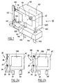
- FIG. 2a the principle of the structure has been represented. internal of a DAF according to the invention.
- the device shown in this figure is of modular type, but the principle of the invention is also applicable to monoblock DAFs.
- the withdrawable cartridge of the DAF comprises an active part 40, connected via two terminals to pads 22 and 23 for plugging into a base such than that described with reference to Figure 1.
- the pad 22 is directly connected to a first conductive part rigid 24, which is located opposite a second rigid conductive part 26 fixed on a first terminal 260 of the active part.
- the two rooms 24 and 26 are fixed, and separated by a space sufficient to prevent passage current between them when said space is cleared.
- the pad 22 and the conductive part 24 can also constitute a unique element.
- a third rigid part 27, or slider is mounted in translation of so as to be able to be engaged in the space separating parts 24 and 26 in a first position in which the cursor establishes a contact electric between the two rooms when said space is free.
- a weld 25, of the type described with reference to FIG. 1, keeps the cursor in said first position and thus links electrically the pads 22 and 23, the second terminal of the active part which is not shown in the figure being directly connected to the stud 23.
- solder 25 can be replaced by a hot melt connection equivalent mechanical characteristics. In this case, it is not necessary to provide additional means to establish contact electric between parts 24 and 26, said contact being ensured by the cursor 27 in its first position.
- the spring 28 can also be compressed between a fixed point 280 of the cartridge and a part 281 secured to the cursor.
- the effect of the spring is the even on the cursor.
- This arrangement is advantageous because it makes it possible to carry out a DAF or a DAF cartridge with a smaller footprint or, equivalent footprint, to integrate additional components, as we will see.
- a cartridge 30 of DAF modular, standard format which can contain according to the state of the art a single varistor, carries on its lower face 301 four studs 22a, 22b, 23a and 23b for plugging into a fixed socket.
- the cartridge 30 according to the invention does not include a braid such that described with reference to Figure 1. This results in space saving which allows to house in the housing 300 of the cartridge two varistors intended for be connected in parallel between the phase wire on the one hand, and on the other hand the neutral or earth of an electrical installation, or between neutral and earth.
- Cartridge 30 includes also two pins 36a and 36b whose role will be explained later in this text, protruding out of the face 301 which is intended to be in contact with the base, the two pins being able to slide in the openings 360a and 360b of said face 301 of the housing 300 for a retraction in the housing.
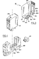
- FIG. 4 is a perspective view of the cartridge 30 and the corresponding base 400, which includes the coding 350.
- Figure 4 also shows a variant of the invention, which consists in providing the base with a socket for the connection of a 410 module remote indication of the cartridge status. We will come back to the means to control this remote signaling.
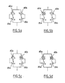
- FIG. 5a to 5d show the four possible states of the two varistors, referenced here 40a and 40b. These two varistors, which are mounted as we said in parallel, are each associated individually to the disconnectors 25a and 25b, respectively.
- the disconnectors 25a and 25b are produced by the combination of the cursor 27 and a fuse link such as the solder 25 of FIG. 2.
- the housing generally paralepipedic 300 of the cartridge 30 contains two subsets identical, one of which will be described here.
- the varistor 40a which is located in the central part of the case, is connected by a first terminal to stud 23a for connection with a base, and by a second terminal 400a to a fuse link 25a which implements a weld as described above.
- the welding of the link 25a maintains a cursor 27a leading electricity in contact with terminal 400a and connection pad 22a with a base, said cursor thus ensuring contact with the weld connection between the terminal and the stud.
- a spring 28a is prestressed in compression, its lower end being linked to the cursor 27a above which the spring is located, and the other end of the spring pressing against a finger 60a secured to the cursor, finger that the spring tends to move away from the face 301 of the cartridge.
- the pin 36a, the link 25a, the terminal 400a and the spring 28a are arranged along a lateral face of the housing adjacent to the face 301.
- a direction I is defined with reference to this figure perpendicular to this lateral face.
- the spring exerts a thrust constant, direction parallel to said lateral face of the housing and directed towards the face of the case opposite the base, on the finger 60a which urges its turn the cursor 27a aligned with the pin 36a and the spring 28a.
- the spring 28a separates the cursor 27a from the solder 25a and drives the finger 60a rigidly secured to the cursor and aligned above it, towards the upper face of the housing which is opposite to the base.
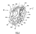
- FIGS. 7a to 7c are diagrams of views in the direction I of FIG. 6, elements of the cartridge 30 in the three possible states of device according to the invention.
- the face that the housing 300 presents in these views is that, lateral, against which the assemblies formed by a spike, a fusible link, a cursor, a spring and a finger secured to the cursor are installed.
- Figures 7d to 7f are three schematic views of the witness 600 seen from the interior of the case 300, corresponding to the states of views 7a to 7c respectively.
- the two identical and parallel fingers 60a and 60b, respectively attached to the sliders linked to the two varistors of the DAF, are at a distance from witness 600, the two links 25a and 25b being provided by the welds of the respective sliders.
- Figure 7a shows the U-shaped section of control 600 which shows one side parallel to the wall of the housing located nearby and two lateral sections 600a and 600b located on the sides of this first face and protruding towards the inside of the housing 300.
- the ends of the two fingers 60a and 60b which are turned towards the witness 600 define a beveled profile with two oblique ramps and opposite to the axis of the finger.
- the ends of the fingers 60a and 60b each defines a protruding V-shaped profile, the two slopes of each V being able to cooperate with the protruding sections of the witness 600 as we will explain.
- the width of the witness defined by the distance between its two sections lateral 600a and 600b, is chosen less than the value of the center distance between the two fingers 60a and 60b.
- the corresponding view 7d shows that the indicator 600, which is mounted at pivoting about an axis 620 which extends substantially parallel to the fingers 60a and 60b, is then in the middle of the face 302 of the case close to which it is implanted. An outside observer looking at this face 302 of the case 300 can then see through a window 610 of said face the position of the witness which completely obstructs orifice 610.
- witness 600 has an extended central portion 6000 extended by a second portion 6001, made of material with the portion 6000, located in its extension and of substantially smaller width.
- the indicator 600 also has two elastic lateral tabs 602a and 602b intended to come selectively to bear on the side walls of the case to stabilize the position of the witness, as we will explain.
- the finger 60b has been moved by the spring which is linked to it following the rupture or the fusion of the corresponding weld.
- the ramp of this finger which is turned towards finger 60a then cooperates with the projecting section 600b of witness 600 to move one end of said witness, which rotates then around axis 620, as shown in Figure 7e.
- the witness In the position of FIG. 7e, the witness is kept in a angular position away from the median axis of the face 302 of the cartridge, on the one hand thanks to the cooperation of the finger 60b with the section 600b, and on the other hand to the elastic support on an internal side wall of the housing 300 of the lateral tab 602b of the witness, elastically deformable.
- witness 600 which is not constant width but has two symmetrical lateral recesses defining a narrower width near its end being in the region of window 610, an outside observer can view the state of the device. Indeed, in this position of the witness 600, the window 610 is only partially obstructed by witness 600 due to its position angular away from the median axis of the face 302.
- the ramp of the finger 60a remote from the finger 60b cooperates with a second projecting section 600a of the witness to further move said witness rotating in the same direction as before.
- An outside observer then visualizes through window 610 the state of the cartridge, the indicator 600 leaving the window completely cleared.
- a user can therefore view the status of the cartridge at any time DAF according to the invention.
- the two sections protruding 600a and 600b of the witness extend respectively opposite symmetrical inclined ramps of the two fingers 60a and 60b, and that the witness 600 is itself symmetrical, the operation of the device is the same regardless of the varistor arriving first at the end of life.
- the device according to the invention is particularly advantageous in that that it has characteristics of reliability and robustness due to the absence of a braid, the bonds of which are a factor of fragility.
- the device according to the invention allows, as has been shown to integrate into a withdrawable DAF cartridge of reduced format two varistors operating according to a reserve system.
- the means of contact of the base with the cartridge can include semi-rigid means conducting electricity, the section of which is in the shape of a "U" so as to define two branches placed opposite between a connector on the base and a connector on the cartridge, each branch being in contact with a respective connector.
- This characteristic generates in said contact means a electrodynamic force tending to spread their branches, when the means contacts are crossed by a current. Said branches go under the action of this spreading force press against the connectors the base and the cartridge, ensuring the quality of the contact between these connectors.
- cartridge sub-assemblies included a solder 25a connecting terminal 400a to a stud 22a.
- This welding also makes it possible to maintain the cursor 27a in a space located between the terminal 400a and the stud 22a, so as to ensure the electrical contact between these two elements.
- varistor 40a is also associated the picot 36a projecting from the so-called lower face 301, through an opening in which it can slide longitudinally in a direction perpendicular to the plane of the face 301.
- the subassembly also includes the spring 28a located at the inside of the case and substantially aligned with the pin 36a and the cursor 27a. It will be noted here that the spring 28a can also be prestressed in extension between a fixed point on the housing away from the base and the cursor, and act on it in the same way as described above.
- the pin 36a is also integral with the cursor 27a so that when said cursor is held between terminal 400a and stud 22a by the solder 25a, the pin 36a protrudes from the face 301 of the housing in protruding from said face by a height H1.
- the pin 36a, the slider 27a and its weld 25a as well as the spring 28a are arranged to be substantially aligned along the same face of the cartridge case 30.
- the spring 28a recalls the cursor and the pin towards the side of the cartridge opposite to the base, said pin then being retracted (partially or completely) in the cartridge.
- the cartridge 30 also includes a second sub-assembly identical to the one just described, implementing a second spring, a second slider and a second pin 36b.
- the welds respectively associated with the two varistors maintain the two pins 36a and 36b projecting from a height H1 outside the cartridge case.
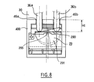
- FIG 8 there is shown in section transverse vertical the cartridge 30 plugged into the base 400, the studs 22, 23 of connection not being shown on this sectional plane which contains the axes of the two pins 36a and 36b.
- the base includes a part 29 comprising a plate rectangular 290 extending substantially parallel to the upper face of the base and a half-disc 291 perpendicular to the plate, one of which side forms an edge 292 with the diameter of the half-disc.
- the half-disc 291 which is located in a housing complementary to the base, can pivot while remaining in the same plane, as well as move in translation towards the upper face of the base.
- the pins 36a and 36b are shown projecting outside the cartridge. In this position, the two pins enter the base by the respective orifices 46a and 46b and are supported on the upper face of the plate 290, on either side of the axis of symmetry of the part 29 which is perpendicular to the edge of the part.
- the center of the underside of the plate is also pressing a 295 microswitch button controlling the signal reversal all or nothing of a remote signaling circuit of the state of the device.
- the three support points on the two sides of the plate are aligned parallel to the edge of the part, creating no moment perpendicular to this edge on the part 29.
- a spring not shown in the figure tends to lift in permanently push button 295.
- the plate has a pressure transmission function pimples to the pusher and presses itself on the top of the pusher, now this one in a so-called low position corresponding to the remote signaling of a device state in which the two varistors are operational.
- the pusher 295 can then be lifted under the action of the spring which permanently requests it, up to a second so-called high position where said pushbutton controls the reversal of electrical signals to signal the fault varistor.
- Figures 9a to 9c schematically represent the positions possible of the pair of pins 36a and 36b of the part 29 and of the pusher 295 controlling the remote signaling signals of the state of the device.
- the two pins 36a and 36b project towards the bottom out of the cartridge, the two varistors associated respectively with these pins being in service.
- the wafer 290 is maintained as we saw it perpendicular to the axes of the pins and the pusher 295 by the equal and diametrically opposite pressures of these two pins, and the said pusher is held down in said low position.
- This low position of the pusher corresponds to the control of electrical signals remotely indicating that the two varistors of the device are in service.
- one of the two pins is retracted inside the cartridge case.
- it is the pin 36b which is retracted.
- the configuration described here is symmetrical and could apply to a situation in which the pin 36a is retracted and the pin 36b is projecting downwards.
- the wafer 290 has, as we have seen pivoted around its point of contact with the pin 36a, and the pusher 295 is in the high position due to the stress of the spring associated with it.
- the pusher In this high position, the pusher signals at a distance that one at least one of the device's two varistors is out of service.
- FIG. 9c the two pins 36a and 36b are retracted.
- the wafer 290 thus finds a position parallel to its position in the figure 9a.
- the push-button 295 remains in this configuration in the high position and thus always signals the device fault remotely.
- the microswitch when inserting a cartridge, the two of which varistors are in service in the base, the microswitch changes state in moving from its high position to its low position (indeed, part 290 is translated from its position illustrated in FIG. 9c to its position illustrated in the Figure 9a when installing a cartridge).
- Such use of a single microswitch to report the condition of a device with two varistors makes it possible to reduce the complexity and the costs linked to the wiring between the microswitches and a remote signaling unit, compared to existing solutions in which a microswitch is associated with each varistor.
Abstract
Description
La présente invention concerne les dispositifs de protection d'installations électriques contre les perturbations de l'alimentation.The present invention relates to protective devices electrical installations against supply disturbances.
Ces dispositifs sont couramment utilisés pour protéger les appareils électriques et électroniques contre les surtensions pouvant être transmises par les réseaux d'alimentation électrique. De telles surtensions peuvent en particulier être générées par des décharges de foudre atteignant les infrastructures des réseaux d'alimentation.These devices are commonly used to protect devices electrical and electronic against surges that can be transmitted by power supply networks. Such overvoltages can especially be generated by lightning strikes reaching power network infrastructures.
Les dispositifs de protection (que l'on désignera dans ce texte par l'appellation DAF « dispositif anti-foudre ») peuvent être intégrés dans un tableau commandant l'alimentation de plusieurs prises électriques, ou être connectés directement en amont de l'appareil à protéger.Protection devices (which will be designated in this text by DAF designation "lightning protection device") can be integrated into a switchboard controlling the supply of several electrical outlets, or be connected directly upstream of the device to be protected.
Les DAF intégrés dans un tableau électrique (DAF de tableau) permettent ainsi de protéger une pluralité d'appareils en écoulant à la terre les surtensions. Parmi les DAF de tableau existants, on distingue :
- d'une part, les DAF monoblocs comprenant dans un boítier
unique :
- une partie active du DAF (utilisant un ou plusieurs éléments de varistance ou d'éclateur à gaz par exemple),

- des éléments de connectique permettant de relier la partie active au circuit à protéger et au circuit d'alimentation (typiquement en parallèle de ceux-ci),

- et éventuellement un système de visualisation de défaut indiquant l'état du DAF et/ou un bornier de télésignalisation de l'état du DAF.

- d'autre part, les DAF modulaires composés :
- d'une embase fixée sur le tableau et intégrant la connectique et un éventuel bornier de télésignalisation,

- et d'une cartouche enfichable de manière amovible sur l'embase, intégrant la partie active et éventuellement le système de visualisation de défaut.

- on the one hand, the monoblock DAF comprising in a single housing:
- an active part of the DAF (using one or more elements of varistor or gas spark gap for example),
- connection elements making it possible to connect the active part to the circuit to be protected and to the supply circuit (typically in parallel with these),
- and possibly a fault display system indicating the state of the DAF and / or a terminal block for remote signaling of the DAF state.
- on the other hand, the modular DAF composed:
- a base fixed to the switchboard and incorporating the connectors and a possible remote signaling terminal block,
- and a cartridge pluggable in a removable manner on the base, integrating the active part and possibly the fault display system.
Les DAF existants, qu'ils soient de type monobloc ou modulaires, mettent en oeuvre des moyens pour relier les broches des éléments de connectique (elles-mêmes en contact avec le circuit d'alimentation et le circuit à protéger) à la partie active du DAF.Existing DAFs, whether of the monobloc or modular type, use means for connecting the pins of the elements of connectors (themselves in contact with the supply circuit and the circuit to be protected) to the active part of the DAF.
Ces moyens comprennent généralement une pièce conductrice de liaison, reliée à une première broche des éléments de connectique et soudée à une première borne de la partie active, dont l'autre borne est directement reliée à la deuxième broche des éléments de connectique.These means generally comprise a conductive part of connection, connected to a first pin of the connector elements and welded to a first terminal of the active part, the other terminal of which is directly connected to the second pin of the connector elements.
Dans une telle configuration, la soudure entre la pièce de liaison et la première borne de la partie active assure ainsi le contact mécanique entre ces deux éléments, et par voie de conséquence la fermeture du circuit de protection électrique formé par les éléments de connectique et la partie active du DAF.In such a configuration, the weld between the connecting piece and the first terminal of the active part thus ensures mechanical contact between these two elements, and consequently the closing of the circuit of electrical protection formed by the connection elements and the part active DAF.
En outre, la soudure est réalisée de manière à ce que lorsque le courant traversant le DAF dépasse des valeurs prédéfinies et caractéristiques du DAF, ou lorsque la partie active qui se trouve à proximité de la soudure provoque un échauffement excessif en arrivant en fin de vie, la liaison assurée par ladite soudure se défasse (par rupture ou fusion de la soudure) pour permettre aux deux éléments qu'elle relie de se désolidariser.In addition, the welding is carried out so that when the current flowing through the DAF exceeds predefined values and characteristics of the DAF, or when the active part which is nearby of the solder causes excessive heating when reaching the end of its life, the connection provided by said weld is undone (by rupture or fusion of the welding) to allow the two elements it connects to separate.
Dans les dispositifs existants, la pièce de liaison est généralement soumise à une contrainte mécanique permanente, tendant à la séparer de la borne de la partie active à laquelle elle est soudée.In existing devices, the connecting piece is generally subjected to a permanent mechanical stress, tending to separate it from the terminal of the active part to which it is welded.
Ainsi, lorsqu'un courant excessif ou une utilisation trop prolongée provoque respectivement la rupture ou la fusion de la soudure, la pièce de liaison s'écarte de la borne de la partie active et le circuit de protection compris dans le DAF est ouvert.So when excessive current or too prolonged use causes respectively the rupture or the fusion of the weld, the part of link deviates from the terminal of the active part and the protection circuit included in the DAF is open.
La contrainte mécanique permanente évoquée plus haut peut résulter d'une déformation élastique avant soudage de la pièce conductrice, comme le décrit par exemple le document EP 0 716 493 au nom de la Demanderesse.The permanent mechanical stress mentioned above may result elastic deformation before welding of the conductive part, as describes it for example the document EP 0 716 493 in the name of the Applicant.
Un autre mode de réalisation connu permettant de mettre en oeuvre cette contrainte mécanique utilise un ressort. Ce mode de réalisation est représenté sur la figure 1, qui est un schéma présentant les principaux sous-ensembles d'un DAF selon l'état de la technique.Another known embodiment making it possible to implement this mechanical stress uses a spring. This embodiment is shown in Figure 1, which is a diagram showing the main subsets a DAF according to the state of the art.
Le DAF de ce schéma est de type modulaire, mais ses sous-ensembles significatifs en regard de l'invention que l'on va décrire peuvent également être intégrés dans un DAF monobloc de type connu.The DAF of this scheme is modular, but its subsets significant with regard to the invention which will be described may also be integrated into a known type of one-piece DAF.
En référence à la figure 1, on a représenté le DAF modulaire 10,
composé d'une cartouche 100 enfichable dans une embase 150. La
cartouche 100 comprend un circuit 40 de protection contre les surtensions
qui peut être de tout type connu utilisant par exemple des varistances. Le
circuit 40 est relié à deux bornes 101 et 102 placées chacune sur une face
latérale de la cartouche.Referring to FIG. 1, the
La cartouche de ce DAF modulaire comprend également deux plots
103 et 104 pour l'enfichage dans deux connecteurs femelles respectifs 151
et 152 de l'embase 150. La borne 102 est directement reliée au plot 104 par
une liaison 1020, tandis que la borne 101 de la face opposée de la cartouche
est reliée à une première pièce 110 rigide et électriquement conductrice.The cartridge of this modular DAF also includes two
Le plot 103 est relié à une première extrémité d'une tresse souple 105
conduisant également l'électricité, dont l'autre extrémité est connectée à une
deuxième pièce rigide ou curseur 120. Le curseur 120 est relié à la pièce
rigide 110 par une soudure 130 conductrice.The
La soudure 130 est une soudure à basse température qui fond
sous l'effet d'une exposition prolongée à une température dépassant
sensiblement 100°C. Cette soudure à une double fonction de maintien
mécanique du curseur 120 en contact avec la pièce rigide 110, et
d'acheminement du courant entre la tresse 105 et la borne 101.Solder 130 is a low temperature solder which melts
under the effect of prolonged exposure to a temperature exceeding
approximately 100 ° C. This weld has a double holding function
Il est également possible selon l'état de la technique de remplacer la
soudure 130 par un élément thermofusible non conducteur ayant une
fonction adhésive (pouvant être réalisé par exemple en cire) assurant la
fonction de maintien mécanique et fondant dans les mêmes conditions
thermiques, associé à un élément électriquement conducteur apte à assurer
une liaison entre la pièce 110 et le curseur 120 tant que l'élément
thermofusible est en place, cet élément de liaison électriquement conducteur
étant cependant automatiquement rompu lors de la fusion de l'élément
thermofusible. Cet élément de liaison électriquement conducteur peut être
formé de un ou plusieurs fils minces et électriquement conducteurs noyés
dans l'élément thermofusible. Le rôle mécanique de ces fils est négligeable,
mais lesdits fils assurent la liaison électrique entre la tresse et la borne 10.
L'élément de liaison électriquement conducteur peut également être
constitué de moyens conducteurs externes à l'élément thermofusible.It is also possible, depending on the state of the art, to replace the
Un ressort 140 sollicite en permanence le curseur 120 pour le
désolidariser de la pièce 110. Dans le présent mode de réalisation, le ressort
est comprimé entre un appui fixe (qui est ici solidaire de l'embase mais peut
prendre appui sur une partie solidaire de la cartouche), et le curseur. Le
ressort peut également être placé selon toute autre configuration classique,
et en particulier exercer une traction sur l'extrémité du curseur opposée à
l'embase 150.A
L'embase 150 comprend deux broches 153 et 154 reliées aux
connecteurs 151 et 152 respectivement. Ces deux broches permettent de
relier le circuit d'alimentation au circuit à protéger via l'embase, qui est
destinée à être fixée à demeure sur un tableau électrique.The
On comprend que lorsque la cartouche 100 est enfichée dans
l'embase 150, un circuit de protection est établi, qui relie en série la broche
153, le plot 103, la tresse 105, le curseur 120 qui est relié à la pièce 110 par
la soudure 130, la borne 101, le circuit 40, la borne 102 et enfin le plot 104 et
la broche 154.It is understood that when the
Un dispositif de ce type a une durée de vie limitée. En arrivant en fin
de vie ses composant s'échauffent, ce qui provoque la fusion de la soudure
130. Le curseur n'étant alors plus lié à la cartouche 100 est repoussé vers le
haut par le ressort et se déplace pour assurer l'arrêt de l'alimentation de la
ligne à protéger par l'ouverture du circuit de protection, ainsi que la
visualisation et éventuellement la commande de la télésignalisation de l'état
de ladite varistance.A device of this type has a limited lifespan. Arriving at the end
of life its components heat up, causing the fusion of the
La soudure 130 peut également être rompue par un choc provoqué
par le passage d'un courant excessif, ce qui entraíne le même déplacement
du curseur.The
Les parafoudres modulaires tels que celui décrit en référence à la figure 1 n'offrent qu'une visualisation binaire de l'état de la partie active, soit que ladite partie soit en état de fonctionner soit qu'elle ait atteint sa fin de vie.Modular surge arresters such as that described with reference to the Figure 1 only offer a binary display of the state of the active part, ie that said part is in working order or that it has reached its end of life.
La Demanderesse a apporté aux DAF modulaires un perfectionnement consistant à doter la cartouche d'une deuxième varistance constituant une « réserve », grâce à laquelle un utilisateur peut visualiser trois états de la partie active du dispositif:
- état normal,
- une des deux varistances est déconnectée - cartouche fonctionnant encore mais à changer,
- les deux varistances sont déconnectées - cartouche hors d'usage.
- normal state,
- one of the two varistors is disconnected - cartridge still working but to be changed,
- the two varistors are disconnected - cartridge out of use.
Cette visualisation de la déconnexion d'une des deux varistances (et donc de l'approche de la fin de vie de la cartouche) permet de disposer d'un laps de temps pour effectuer le changement de la cartouche, tout en gardant active la protection de l'installation électrique grâce à la varistance restant en service. Une cartouche de DAF à réserve est décrite dans le brevet EP 0 716 493 au nom de la Demanderesse.This visualization of the disconnection of one of the two varistors (and approaching the end of life of the cartridge) provides a time to change the cartridge while keeping activates the protection of the electrical installation thanks to the varistor remaining in service. A reserve DAF cartridge is described in patent EP 0 716 493 in the name of the Claimant.
Par ailleurs, par suite de l'uniformisation des formats des matériels basse tension, les DAF existants ont généralement des dimensions standardisées pour faciliter leur intégration dans des tableaux différents (hauteur de 58 mm en particulier).In addition, as a result of the standardization of the formats of the materials low voltage, existing DAFs generally have dimensions standardized to facilitate their integration into different tables (58 mm high in particular).
Un inconvénient des DAF du type de celui décrit en référence à la figure 1, qu'ils soient modulaire ou monobloc, est que la présence de la tresse complexifie le montage du dispositif, en nécessitant des points de soudure ou de sertissage supplémentaires qui tendent à fragiliser l'ensemble, et à augmenter les risques de panne.A drawback of DAFs of the type described with reference to the figure 1, whether modular or monobloc, is that the presence of the braid complicates the mounting of the device, requiring points of additional soldering or crimping which tend to weaken overall, and to increase the risk of breakdown.
Un autre inconvénient des DAF du type de celui décrit en référence à la figure 1, lié au format standard évoqué plus haut, est que par suite de la présence de la tresse qui présente un encombrement non négligeable, les circuits des cartouches des DAF modulaires de format standard ne peuvent contenir qu'une seule varistance.Another drawback of DAFs of the type described with reference to Figure 1, linked to the standard format mentioned above, is that as a result of the presence of the braid which presents a non-negligible bulk, the cartridge circuits of standard format modular DAFs cannot contain only one varistor.
Cette limitation interdit l'intégration des dispositifs à réserve évoqués plus haut, qui nécessitent l'emploi de deux varistances montées en parallèle dans la cartouche du DAF. Par suite, l'intensité du courant que le DAF peut écouler à la terre est limité à une valeur de l'ordre de 40 kA 8/20, ce qui est insuffisant pour certaines applications.This limitation prohibits the integration of the reserve devices mentioned above, which require the use of two varistors mounted in parallel in the DAF cartridge. As a result, the intensity of the current that the DAF can flow to the ground is limited to a value of the order of 40 kA 8/20, which is insufficient for certain applications.
Un but de la présente invention est de permettre de réaliser des DAF de structure simple et fiable, ne comprenant pas de tresse qui constituerait un élément encombrant et fragilisant.An object of the present invention is to make it possible to perform DAFs simple and reliable structure, not including a braid which would constitute a bulky and weakening element.
Un deuxième but de l'invention est de permettre d'élaborer un DAF débrochable selon la caractéristique énoncée au paragraphe précédent, dans laquelle la cartouche est capable d'écouler à la terre un courant d'intensité de l'ordre de 65 kA 8/20, la géométrie de la cartouche respectant les dimensions standard imposant en particulier une hauteur de 58 mm.A second object of the invention is to make it possible to develop a DAF withdrawable according to the characteristic stated in the previous paragraph, in which the cartridge is capable of flowing a current to the ground intensity of the order of 65 kA 8/20, the geometry of the cartridge respecting standard dimensions requiring in particular a height of 58 mm.
Pour atteindre ces buts, l'invention propose un dispositif de protection contre des surtensions d'appareils électriques auxquels le dispositif est relié via des moyens de connexion comportant au moins deux connecteurs, le dispositif comprenant également une cellule parafoudre dont un premier pôle est directement relié à un premier desdits connecteurs, caractérisé en ce qu'un deuxième pôle de la cellule est connecté à une première pièce conductrice, en ce que le dispositif comprend également une deuxième pièce conductrice directement reliée à un deuxième desdits connecteurs et en ce que le dispositif comprend également des moyens de liaison fusible pour maintenir un curseur rigide en contact électrique avec lesdites pièces conductrices dans une position de fonctionnement du dispositif, des moyens étant prévus pour solliciter en permanence le curseur vers une position d'ouverture du dispositif dans laquelle ledit curseur n'est plus en contact avec les deux pièces conductrices.To achieve these goals, the invention provides a protection device against overvoltages of electrical devices to which the device is connected via connection means comprising at least two connectors, the device also comprising a lightning protection cell including a first pole is directly connected to a first of said connectors, characterized in that that a second pole of the cell is connected to a first part conductive, in that the device also comprises a second part conductive directly connected to a second of said connectors and in that that the device also includes fusible link means for maintain a rigid cursor in electrical contact with said parts conductive in an operating position of the device, means being adapted to permanently urge the cursor to a position opening of the device in which said cursor is no longer in contact with the two conductive parts.
Des aspects préférés, mais non limitatifs du dispositif selon l'invention sont les suivants:
- lesdites pièces conductrices sont rigides ,
- la liaison fusible utilise une soudure à basse température dont le point de fusion est voisin de 100°C ,
- le dispositif est de type débrochable et comporte d'une part une embase destinée à être fixée sur un tableau électrique, et d'autre part une cartouche enfichable sur l'embase et comprenant la cellule parafoudre, les deux pièces conductrices ainsi que le curseur, des moyens de contact électrique étant prévus entre l'embase et la cartouche ,
- la cartouche comprend une deuxième cellule parafoudre dont un premier pôle est directement relié à un troisième desdits connecteurs, en ce que le deuxième pôle de la deuxième cellule est connecté à une troisième pièce conductrice, en ce que le dispositif comprend également une quatrième pièce conductrice directement reliée à un quatrième desdits connecteurs et en ce que le dispositif comprend également un deuxième curseur rigide assurant une liaison électrique fusible entre lesdites troisième et quatrième pièces conductrices dans une position de fonctionnement du dispositif, des moyens étant prévus pour solliciter en permanence le deuxième curseur vers une position dans laquelle ledit deuxième curseur n'est plus en contact avec les troisième et quatrième pièces conductrices ,
- les troisième et quatrième connecteur sont confondus avec les premier et deuxième connecteur, respectivement ,
- le dispositif comporte des moyens mécaniques de visualisation de l'état de chacune des cellules parafoudres ,
- les moyens de visualisation comportent des doigts aptes à coopérer avec une pièce mobile du dispositif,
- les moyens de visualisation sont adaptés pour distinguer les cas où :
- (a) les deux varistances sont en service,
- (b) l'une des deux varistances est déconnectée,
- (c) les deux varistances sont déconnectées ,
- la hauteur entre d'une part un point de contact de l'embase avec le tableau électrique et d'autre part l'extrémité de la cartouche se trouvant à l'aplomb dudit point de contact lorsque la cartouche est enfichée sur l'embase n'excède pas 58 millimètres,
- il est prévu des moyens de télésignalisation de l'état de la cartouche,
- les moyens de contact électrique entre l'embase et la cartouche comprennent des éléments dont chacun comporte au moins deux branches, la forme des branches de chaque élément étant telle que la circulation d'un courant dans lesdites branches engendre une force électrodynamique tendant à écarter les branches ,
- lesdits éléments sont des éléments souples ou rigides en forme
générale de « U »,
- chacun desdits éléments comporte deux branches opposées
situées entre un moyen de connexion de l'embase et un moyen de
connexion de la cartouche,
- la cartouche comprend deux circuits de protection contre les surtensions et l'embase comprend un interrupteur unique à deux positions, actionné par des éléments de signalisation de l'état respectif des deux circuits de protection, une première position de l'interrupteur correspondant à un état du dispositif dans lequel les deux circuits de protection sont actifs, la deuxième position de l'interrupteur correspondant à l'un des états suivants du dispositif:
- un des deux circuits de protection hors service,
- les deux circuits de protection hors service,
- absence de cartouche dans le dispositif,
- chacun desdits éléments comporte deux branches opposées
situées entre un moyen de connexion de l'embase et un moyen de
connexion de la cartouche,
- lesdits éléments de signalisation sont des picots saillants hors d'une face de la cartouche se trouvant au contact de l'embase lorsque la cartouche est enfichée dans l'embase,
- chaque picot est maintenu en position saillante hors du boítier par une liaison fusible respective, ladite liaison fusible libérant le picot lui correspondant lors de l'arrivée en fin de vie du circuit de protection qu'elle maintient, un ressort associé au picot escamotant alors ledit picot dans la cartouche,
- l'embase comprend une pièce dont une première face est en appui sur l'interrupteur, les éléments de signalisation étant aptes à venir en appui sur une deuxième face opposée de ladite pièce,
- ladite pièce de l'embase est apte à basculer sélectivement autour de chacun des deux axes de ladite première face perpendiculaires à une ligne joignant les axes longitudinaux respectifs des deux éléments de signalisation et passant par les deux points de contact respectifs de ladite face avec lesdits éléments de signalisation,
- les projections des points d'appui sur ladite pièce des éléments de signalisation et de l'interrupteur dans le plan de ladite première face de ladite pièce sont alignées,
- dans ledit plan les projections des points d'appui des éléments de signalisation sont disposées symétriquement par rapport à la projection du point d'appui de l'interrupteur,
- l'interrupteur est précontraint mécaniquement pour solliciter ladite deuxième face de la pièce dans la direction opposée à la sollicitation des éléments de signalisation.
- said conductive parts are rigid,
- the fuse link uses a low temperature solder whose melting point is close to 100 ° C,
- the device is of the withdrawable type and comprises on the one hand a base intended to be fixed on an electrical panel, and on the other hand a cartridge pluggable on the base and comprising the arrester cell, the two conductive parts as well as the cursor, electrical contact means being provided between the base and the cartridge,
- the cartridge comprises a second surge arrester cell, a first pole of which is directly connected to a third of said connectors, in that the second pole of the second cell is connected to a third conductive part, in that the device also comprises a fourth conductive part directly connected to a fourth of said connectors and in that the device also comprises a second rigid cursor ensuring a fusible electrical connection between said third and fourth conductive parts in an operating position of the device, means being provided for permanently urging the second cursor towards a position in which said second cursor is no longer in contact with the third and fourth conductive parts,
- the third and fourth connectors are merged with the first and second connectors, respectively,
- the device comprises mechanical means for displaying the state of each of the surge arresters,
- the display means include fingers capable of cooperating with a moving part of the device,
- the display means are adapted to distinguish the cases where:
- (a) both varistors are in service,
- (b) one of the two varistors is disconnected,
- (c) the two varistors are disconnected,
- the height between on the one hand a point of contact of the base with the electrical panel and on the other hand the end of the cartridge being in line with said point of contact when the cartridge is inserted on the base n '' does not exceed 58 millimeters,
- means are provided for remote signaling of the state of the cartridge,
- the means of electrical contact between the base and the cartridge comprise elements each of which comprises at least two branches, the shape of the branches of each element being such that the circulation of a current in said branches generates an electrodynamic force tending to spread the branches,
- said elements are flexible or rigid elements in the general shape of a "U",
- each of said elements comprises two opposite branches situated between a connection means of the base and a connection means of the cartridge,
- the cartridge comprises two overvoltage protection circuits and the base comprises a single switch with two positions, actuated by elements for signaling the respective state of the two protection circuits, a first position of the switch corresponding to a state of the device in which the two protection circuits are active, the second position of the switch corresponding to one of the following states of the device:
- one of the two protective circuits out of service,
- the two protective circuits out of service,
- no cartridge in the device,
- each of said elements comprises two opposite branches situated between a connection means of the base and a connection means of the cartridge,
- said signaling elements are protruding pins outside one face of the cartridge being in contact with the base when the cartridge is inserted in the base,
- each pin is held in the projecting position outside the housing by a respective fuse link, said fuse link releasing the pin corresponding to it when the end of life of the protection circuit which it maintains, a spring associated with the pin then retracting said pin in the cartridge,
- the base comprises a part, a first face of which bears on the switch, the signaling elements being capable of coming to bear on a second opposite face of said part,
- said part of the base is capable of tilting selectively around each of the two axes of said first face perpendicular to a line joining the respective longitudinal axes of the two signaling elements and passing through the two respective points of contact of said face with said elements signaling,
- the projections of the support points on said part of the signaling elements and of the switch in the plane of said first face of said part are aligned,
- in said plane, the projections of the support points of the signaling elements are arranged symmetrically with respect to the projection of the support point of the switch,
- the switch is mechanically prestressed to urge said second face of the part in the direction opposite to the urging of the signaling elements.
D'autres aspects, buts et avantages de l'invention apparaítront mieux à la description suivante d'une forme de réalisation préférée de celle-ci, donnée à titre d'exemple et faite en référence aux dessins annexés, sur lesquels :
- la figure 1 est un schéma de principe d'un DAF selon l'état de la technique, dans un mode de réalisation où le DAF est débrochable,
- les figures 2a et 2b sont des schémas de type bloc-diagramme de deux variantes d'un DAF selon l'invention,
- la figure 3 est une vue en perspective d'une cartoüche de DAF débrochable selon l'invention,
- la figure 4 est une vue en perspective d'un mode de réalisation d'un DAF débrochable selon l'invention,
- les figures 5a à 5d sont des représentations schématiques des états possibles du circuit de la partie active d'un DAF selon l'invention,
- la figure 6 est une vue éclatée précisant la structure interne d'une cartouche de DAF selon l'invention,
- les figures 7a à 7f sont des schémas représentant les différents états du système de visualisation de défaut d'un DAF selon l'invention,
- la figure 8 est une représentation schématique en coupe verticale transversale des éléments permettant de commander un bornier de télésignalisation de l'état de la cartouche d'un DAF modulaire selon l'invention,
- les figures 9a à 9c sont des représentations en perspective d'une partie de ces éléments de commande, à trois étapes respectives de leur fonctionnement.
- FIG. 1 is a block diagram of a DAF according to the state of the art, in an embodiment where the DAF is withdrawable,
- FIGS. 2a and 2b are block diagram diagrams of two variants of a DAF according to the invention,
- FIG. 3 is a perspective view of a withdrawable DAF cartridge according to the invention,
- FIG. 4 is a perspective view of an embodiment of a withdrawable DAF according to the invention,
- FIGS. 5a to 5d are schematic representations of the possible states of the circuit of the active part of a DAF according to the invention,
- FIG. 6 is an exploded view specifying the internal structure of a DAF cartridge according to the invention,
- FIGS. 7a to 7f are diagrams representing the different states of the fault display system of a DAF according to the invention,
- FIG. 8 is a schematic representation in transverse vertical section of the elements making it possible to control a terminal for remote signaling of the state of the cartridge of a modular DAF according to the invention,
- Figures 9a to 9c are perspective representations of part of these control elements, in three respective stages of their operation.
En référence à la figure 2a, on a représenté le principe de la structure interne d'un DAF selon l'invention. Le dispositif représenté sur cette figure est de type modulaire, mais le principe de l'invention est également applicable aux DAF monoblocs.With reference to FIG. 2a, the principle of the structure has been represented. internal of a DAF according to the invention. The device shown in this figure is of modular type, but the principle of the invention is also applicable to monoblock DAFs.
La cartouche débrochable du DAF comprend une partie active 40,
reliée via deux bornes aux plots 22 et 23 d'enfichage dans une embase telle
que celle décrite en référence à la figure 1. The withdrawable cartridge of the DAF comprises an
Le principe de l'invention est comme on l'a dit applicable aux DAF
monoblocs; dans ce cas le schéma de la figure 2a reste applicable, les
éléments 22 et 23 correspondant alors aux broches de connexion avec le
circuit à protéger.The principle of the invention is as we said applicable to DAF
monoblocks; in this case the diagram of Figure 2a remains applicable, the
Le plot 22 est directement relié à une première pièce conductrice
rigide 24, qui se trouve en regard d'une deuxième pièce conductrice rigide 26
fixée sur une première borne 260 de la partie active. Les deux pièces 24 et
26 sont fixes, et séparées par un espace suffisant pour interdire le passage
du courant entre elles lorsque ledit espace est dégagé. Dans une variante de
l'invention, le plot 22 et la pièce conductrice 24 peuvent également constituer
un élément unique.The
Une troisième pièce rigide 27, ou curseur, est montée à translation de
manière à pouvoir être engagée dans l'espace séparant les pièces 24 et 26
dans une première position dans laquelle le curseur établit un contact
électrique entre les deux pièces lorsque ledit espace est libre.A third
Une soudure 25, du type de celle décrite en référence à la figure 1,
permet de maintenir le curseur dans ladite première position et de relier ainsi
électriquement les plots 22 et 23, la deuxième borne de la partie active qui
n'est pas représentée sur la figure étant directement reliée au plot 23.A
Comme dans le dispositif connu décrit en référence à la figure 1, la
soudure 25 peut être remplacée par une liaison thermofusible de
caractéristiques mécaniques équivalentes. Dans ce cas, il n'est pas
nécessaire de prévoir des moyens supplémentaires pour établir le contact
électrique entre les pièces 24 et 26, ledit contact étant assuré par le curseur
27 dans sa première position.As in the known device described with reference to Figure 1, the
Un ressort 28, dont un côté est fixé à l'extrémité du curseur opposé à
la soudure 25, et l'autre côté fixé à un élément fixe de la cartouche non
représentée sur la figure, est maintenu en extension de manière à solliciter
en permanence le curseur pour qu'il quitte sa première position décrite plus
haut, et rejoigne une deuxième position dans laquelle le curseur n'est plus en
contact avec les pièces 24 et 26. A
Selon l'invention et comme représenté sur la figure 2b, le ressort 28
peut également être comprimé entre un point fixe 280 de la cartouche et une
pièce 281 solidaire du curseur. Dans cette variante, l'effet du ressort est le
même sur le curseur.According to the invention and as shown in Figure 2b, the
On comprend que le résultat du fonctionnement de ce dispositif est le
même que celui du dispositif connu de la figure 1. La différence essentielle
entre les deux dispositifs réside dans l'ajout, dans le dispositif selon
l'invention, du curseur 120 qui permet de s'affranchir d'une tresse
conductrice.We understand that the result of the operation of this device is the
same as that of the device known in FIG. 1. The essential difference
between the two devices lies in the addition, in the device according to
the invention, the
Cette disposition est avantageuse car elle permet de réaliser un DAF ou une cartouche de DAF avec un encombrement moindre ou, à encombrement équivalent, d'intégrer des composants supplémentaires, comme on va le voir.This arrangement is advantageous because it makes it possible to carry out a DAF or a DAF cartridge with a smaller footprint or, equivalent footprint, to integrate additional components, as we will see.
En référence maintenant à la figure 3, une cartouche 30 de DAF
modulaire, de format standard pouvant contenir selon l'état de la technique
une varistance unique, porte sur sa face inférieure 301 quatre plots 22a, 22b,
23a et 23b pour l'enfichage dans une embase fixe.Referring now to Figure 3, a
Le fait de disposer pour la connexion entre la cartouche et l'embase de quatre plots au lieu de deux autorise ainsi, à section égale des plots, le passage d'un courant d'une intensité supérieure entre la cartouche et l'embase.The fact of having for the connection between the cartridge and the base of four studs instead of two thus authorizes, with equal cross-section of the studs, the passage of a current of higher intensity between the cartridge and the base.
La cartouche 30 selon l'invention ne comprend pas de tresse telle que
décrite en référence à la figure 1. Ceci entraíne un gain de place qui permet
de loger dans le boítier 300 de la cartouche deux varistances destinées à
être connectées en parallèle entre le fil de phase d'une part, et d'autre part le
neutre ou la terre d'une installation électrique, ou entre le neutre et la terre.The
Les deux varistances sont reliées aux plots 22a et 23a d'une part, et
22b et 23b d'autre part, respectivement. La cartouche 30 comprend
également deux picots 36a et 36b dont le rôle sera expliqué plus loin dans ce
texte, saillants hors de la face 301 qui est destinée à être en contact avec
l'embase, les deux picots pouvant coulisser dans les ouvertures 360a et
360b de ladite face 301 du boítier 300 pour un escamotage dans le boítier.The two varistors are connected to the
Afin de garantir le sens de la polarité de la connexion de la cartouche
sur son embase par un opérateur, la face inférieure 301 comprend
également un détrompeur 35 destiné à coopérer avec un organe
correspondant de l'embase. La figure 4 est une vue en perspective de la
cartouche 30 et de l'embase 400 correspondante, qui comprend l'organe de
détrompage 350.To ensure the correct polarity of the cartridge connection
on its base by an operator, the
La figure 4 présente également une variante de l'invention, qui consiste à munir l'embase d'une prise pour la connexion d'un module 410 de télésignalisation de l'état de la cartouche. On reviendra sur les moyens permettant de commander cette télésignalisation.Figure 4 also shows a variant of the invention, which consists in providing the base with a socket for the connection of a 410 module remote indication of the cartridge status. We will come back to the means to control this remote signaling.
Les figures 5a à 5d représentent les quatre états possibles des deux
varistances, référencées ici 40a et 40b. Ces deux varistances, qui sont
montées comme on l'a dit en parallèle, sont chacune associées
individuellement aux déconnecteurs 25a et 25b, respectivement. En pratique,
les déconnecteurs 25a et 25b sont réalisés par la combinaison du curseur 27
et d'une liaison fusible telle que la soudure 25 de la figure 2.Figures 5a to 5d show the four possible states of the two
varistors, referenced here 40a and 40b. These two varistors, which are
mounted as we said in parallel, are each associated
individually to the
On pourra se référer au texte du brevet EP 0 716 493 au nom de la Demanderesse pour une explication détaillée du circuit formé par les varistances et les déconnecteurs, qui correspondent ici respectivement aux parties actives et aux liaisons fusibles et curseur du dispositif selon l'invention.Reference may be made to the text of patent EP 0 716 493 in the name of the Applicant for a detailed explanation of the circuit formed by the varistors and disconnectors, which correspond here respectively to active parts and to the fuses and cursor links of the device according to the invention.
En référence maintenant à la figure 6, le boítier généralement
paralépipédique 300 de la cartouche 30 contient deux sous-ensembles
identiques dont on va ici décrire l'un.Referring now to Figure 6, the housing generally
paralepipedic 300 of the
La varistance 40a, qui est située dans la partie centrale du boítier, est
reliée par une première borne au plot 23a de connexion avec une embase, et
par une deuxième borne 400a à une liaison fusible 25a qui met en oeuvre
une soudure telle que décrite précédemment. The
La soudure de la liaison 25a maintient un curseur 27a conduisant
l'électricité en contact avec la borne 400a et le plot 22a de connexion avec
une embase, ledit curseur assurant ainsi avec la soudure le contact
électrique entre la borne et le plot.The welding of the
Un ressort 28a est précontraint en compression, son extrémité basse
étant liée au curseur 27a au-dessus duquel le ressort est situé, et l'autre
extrémité du ressort étant en appui contre un doigt 60a solidaire du curseur,
doigt que le ressort tend à éloigner de la face 301 de la cartouche.A
A l'intérieur du boítier 300, le picot 36a, la liaison 25a, la borne 400a et
le ressort 28a sont disposés le long d'une face latérale du boítier adjacente à
la face 301. On définit en référence à cette figure une direction I
perpendiculaire à cette face latérale.Inside the
Sous l'effet de sa compression, le ressort exerce une poussée
constante, de direction parallèle à ladite face latérale du boítier et dirigée
vers la face du boítier opposée à l'embase, sur le doigt 60a qui sollicite à son
tour le curseur 27a aligné avec le picot 36a et le ressort 28a.Under the effect of its compression, the spring exerts a thrust
constant, direction parallel to said lateral face of the housing and directed
towards the face of the case opposite the base, on the
La poussée constante évoquée plus haut tend ainsi à séparer ledit
curseur de la soudure 25a, de la borne 400a et du plot 23a, ce qui provoque
l'ouverture du circuit comprenant la varistance 40a située entre les plots 22a
et 23a.The constant thrust mentioned above thus tends to separate the said
cursor of
Lorsque maintenant la soudure 25a cède, sous l'effet du passage d'un
courant excessif ou d'un échauffement dû à l'arrivée en fin de vie de la
varistance, le ressort 28a sépare le curseur 27a de la soudure 25a et
entraíne le doigt 60a rigidement solidaire du curseur et aligné au-dessus de
celui-ci, vers la face supérieure du boítier qui est opposée à l'embase.When now the
On va maintenant expliquer le second rôle du doigt 60a, qui intervient
également pour la signalisation de l'état de la varistance 26a.We will now explain the second role of
La soudure ayant cédé et le doigt 60a s'étant déplacé en s'éloignant
de l'embase, le doigt agit sur un témoin 600 constitué d'une palette placée
dans le boítier 300 contre la face opposée à l'embase, comme on va
l'expliquer en référence aux figures 7a à 7c. The weld having given way and the
Les figures 7a à 7c sont des schémas de vues selon la direction I de
la figure 6, des éléments de la cartouche 30 dans les trois états possibles du
dispositif selon l'invention.FIGS. 7a to 7c are diagrams of views in the direction I of
FIG. 6, elements of the
La face que le boítier 300 présente sur ces vues est celle, latérale,
contre laquelle les ensembles formés d'un picot, d'une liaison fusible, d'un
curseur, d'un ressort et d'un doigt solidaire du curseur sont implantée.The face that the
Les figures 7d à 7f sont trois vues schématiques du témoin 600 vu de
l'intérieur du boítier 300, correspondant aux états des vues 7a à 7c
respectivement.Figures 7d to 7f are three schematic views of the
En référence à la figure 7a, les deux doigts identiques et parallèles
60a et 60b, solidaires respectivement des curseurs liés aux deux varistances
du DAF, sont à distance du témoin 600, les deux liaisons 25a et 25b étant
assurées par les soudures des curseurs respectifs.With reference to FIG. 7a, the two identical and
La figure 7a montre la section en U du témoin 600 qui présente
une face parallèle à la paroi du boítier se trouvant à proximité et deux
sections latérales 600a et 600b situées sur les côtés de cette première face
et saillantes vers l'intérieur du boítier 300.Figure 7a shows the U-shaped section of
Les extrémités des deux doigts 60a et 60b qui sont tournées vers le
témoin 600 définissent un profil biseauté à deux rampes obliques et
opposées par rapport à l'axe du doigt. Les extrémités des doigts 60a et 60b
définissent ainsi chacune un profil en forme de V saillant, les deux pentes de
chaque V pouvant coopérer avec les sections saillantes du témoin 600
comme on va l'expliquer.The ends of the two
Dans la position représentée sur la figure 7a, les deux varistances du
dispositif sont connectées et donc les deux doigts 60a et 60b solidaires
respectivement des curseurs liés aux deux varistances sont dans une
position éloignée du témoin 600. Le témoin 600 s'étend alors selon l'axe
longitudinal de la face 302, opposée à l'embase, près de laquelle il est situé.In the position shown in Figure 7a, the two varistors of the
device are connected and therefore the two
La largeur du témoin, définie par la distance entre ses deux sections
latérales 600a et 600b, est choisie inférieure à la valeur de l'entre-axe entre
les deux doigts 60a et 60b. The width of the witness, defined by the distance between its two sections
lateral 600a and 600b, is chosen less than the value of the center distance between
the two
Par conséquent, dans la position représentée sur la figure 7a dans
laquelle le témoin 600 est situé au milieu de la face 302, les sections
saillantes du témoin se trouvent en regard de la rampe de l'extrémité du doigt
60a qui est tournée vers le doigt 60b, et de la rampe de l'extrémité du doigt
60b qui est tournée vers le doigt 60a, respectivement.Therefore, in the position shown in Figure 7a in
which
La vue 7d correspondante montre que le témoin 600, qui est monté à
pivotement autour d'un axe 620 qui s'étend sensiblement parallèlement aux
doigts 60a et 60b, est alors au milieu de la face 302 du boítier à proximité de
laquelle il est implanté. Un observateur extérieur regardant cette face 302 du
boítier 300 peut alors constater par une fenêtre 610 de ladite face la position
du témoin qui obstrue entièrement l'orifice 610.The corresponding view 7d shows that the
Le témoin 600 comporte une portion allongée centrale 6000 prolongée
par une deuxième portion 6001, venue de matière avec la portion 6000,
située dans son prolongement et de largeur sensiblement inférieure. Le
témoin 600 comporte également deux languettes latérales élastiques 602a et
602b destinées à venir sélectivement en appui sur les parois latérales du
boítier pour stabiliser la position du témoin, comme on va l'expliquer.
Sur la vue 7b, le doigt 60b a été déplacé par le ressort qui lui est lié
suite à la rupture ou la fusion de la soudure correspondante. La rampe de ce
doigt qui est tournée vers le doigt 60a coopère alors avec la section saillante
600b du témoin 600 pour déplacer une extrémité dudit témoin, qui tourne
alors autour de l'axe 620, comme indiqué sur la figure 7e.In view 7b, the
Dans la position de la figure 7e, le témoin est maintenu dans une
position angulaire écartée de l'axe médian de la face 302 de la cartouche,
grâce d'une part à la coopération du doigt 60b avec la section 600b, et
d'autre part à l'appui élastique sur une paroi latérale interne du boítier 300 de
la patte latérale 602b du témoin, déformable élastiquement.In the position of FIG. 7e, the witness is kept in a
angular position away from the median axis of the
Grâce à la géométrie particulière du témoin 600 qui n'est pas de
largeur constante mais comporte deux décrochements latéraux symétriques
définissant une largeur moins importante près de son extrémité se trouvant
dans la région de la fenêtre 610, un observateur extérieur peut visualiser
l'état du dispositif. En effet, dans cette position du témoin 600, la fenêtre 610
n'est que partiellement obstruée par le témoin 600 du fait de sa position
angulaire écartée de l'axe médian de la face 302.Thanks to the special geometry of
Lorsque la deuxième varistance arrive en fin de vie à son tour de sorte
que le doigt 60a est à son tour entraíné vers le témoin 600 par son ressort
respectif, la rampe du doigt 60a éloignée du doigt 60b coopère avec une
deuxième section saillante 600a du témoin pour déplacer encore ledit témoin
en rotation dans le même sens que précédemment. Un observateur extérieur
visualise alors par la fenêtre 610 l'état de la cartouche, le témoin 600 laissant
la fenêtre entièrement dégagée.When the second varistor in turn reaches its end of life,
that the
Un utilisateur peut ainsi à tout moment visualiser l'état de la cartouche
du DAF selon l'invention. On comprend qu'étant donné que les deux sections
saillantes 600a et 600b du témoin s'étendent respectivement en regard de
rampes inclinées symétriques des deux doigts 60a et 60b, et que le témoin
600 est lui-même symétrique, le fonctionnement du dispositif est le même
quelle que soit la varistance arrivant la première en fin de vie.A user can therefore view the status of the cartridge at any time
DAF according to the invention. We understand that since the two sections
protruding 600a and 600b of the witness extend respectively opposite
symmetrical inclined ramps of the two
En effet, seul le sens de rotation du témoin 600 autour de l'axe 620
varie en fonction de la varistance qui est déconnectée en premier. Les
décrochements et les déplacements du témoin étant symétriques, la
signalisation de l'état de la cartouche est indépendant de l'identité de la
première varistance à être déconnectée.In fact, only the direction of rotation of the
Si besoin, on trouvera dans le document EP 0 716 493 une description plus détaillée du principe de fonctionnement d'un DAF à deux varistances formant réserve.If necessary, a description can be found in document EP 0 716 493 more detail of the operating principle of a DAF with two varistors forming a reserve.
Le dispositif selon l'invention est particulièrement avantageux en ce qu'il présente des caractéristiques de fiabilité et de robustesse dues à l'absence de tresse dont les liaisons sont un facteur de fragilité.The device according to the invention is particularly advantageous in that that it has characteristics of reliability and robustness due to the absence of a braid, the bonds of which are a factor of fragility.
En outre, le dispositif selon l'invention permet comme on l'a montré d'intégrer dans une cartouche de DAF débrochable de format réduit deux varistances fonctionnant selon un système de réserve. In addition, the device according to the invention allows, as has been shown to integrate into a withdrawable DAF cartridge of reduced format two varistors operating according to a reserve system.
Selon une caractéristique de l'invention non représentée sur les figures, les moyens de contact de l'embase avec la cartouche peuvent comprendre des moyens semi-rigides conduisant l'électricité, dont la section est en forme de « U » de manière à définir deux branches placées en vis-à-vis entre un connecteur de l'embase et un connecteur de la cartouche, chaque branche étant en contact avec un connecteur respectif.According to a characteristic of the invention not shown in the Figures, the means of contact of the base with the cartridge can include semi-rigid means conducting electricity, the section of which is in the shape of a "U" so as to define two branches placed opposite between a connector on the base and a connector on the cartridge, each branch being in contact with a respective connector.
Cette caractéristique engendre dans lesdits moyens de contact une force électrodynamique tendant à écarter leurs branches, lorsque les moyens de contact sont traversés par un courant. Lesdites branches vont sous l'action de cette force d'écartement se plaquer contre les connecteurs respectifs de l'embase et de la cartouche, assurant la qualité du contact électrique entre ces connecteurs.This characteristic generates in said contact means a electrodynamic force tending to spread their branches, when the means contacts are crossed by a current. Said branches go under the action of this spreading force press against the connectors the base and the cartridge, ensuring the quality of the contact between these connectors.
Ainsi réduit-on sensiblement le risque de mauvais contact électrique entre les connecteurs de l'embase et de la cartouche, qui peut entraíner un échauffement, voire l'apparition d'arcs électriques dans la zone de connexion entre l'embase et la cartouche.This significantly reduces the risk of poor electrical contact between the connectors of the base and the cartridge, which can cause overheating, or even the appearance of electric arcs in the connection area between the base and the cartridge.
En référence à nouveau à la figure 6, on va maintenant décrire une deuxième caractéristique du dispositif selon l'invention, indépendante en elle-même des caractéristiques déjà décrites.Referring again to Figure 6, we will now describe a second characteristic of the device according to the invention, independent in characteristics already described.
On a dit que les sous-ensembles de la cartouche comprenait une
soudure 25a reliant la borne 400a à un plot 22a.It was said that the cartridge sub-assemblies included a
Cette soudure permet également de maintenir le curseur 27a dans
un espace situé entre la borne 400a et le plot 22a, de manière à assurer le
contact électrique entre ces deux éléments.This welding also makes it possible to maintain the
D'autre part, à la varistance 40a est également associé le picot
36a saillant hors de la face dite inférieure 301, par une ouverture dans
laquelle il peut coulisser longitudinalement selon une direction
perpendiculaire au plan de la face 301.On the other hand, with
Le sous-ensemble comporte également le ressort 28a situé à
l'intérieur du boítier et sensiblement aligné avec le picot 36a et le curseur
27a. On notera ici que le ressort 28a peut également être précontraint en
extension entre un point fixe du boítier éloigné de l'embase et le curseur, et
agir sur ce dernier de la même manière que décrit ci-dessus.The subassembly also includes the
Le picot 36a est également solidaire du curseur 27a si bien que
lorsque ledit curseur est maintenu entre la borne 400a et le plot 22a par la
soudure 25a, le picot 36a est saillant hors de la face 301 du boítier en
dépassant de ladite face d'une hauteur H1.The
Le picot 36a, le curseur 27a et sa soudure 25a ainsi que le ressort
28a sont agencés de manière à être sensiblement alignés le long de la
même face du boítier de la cartouche 30.The
Dans le cas où la soudure ne maintient plus le curseur (par suite
du passage d'un courant de choc provoquant la cassure de la soudure, ou
de la fusion de la soudure suite à un échauffement prolongé de la varistance
arrivant en fin de vie), le ressort 28a rappelle le curseur et le picot vers le
côté de la cartouche opposée à l'embase, ledit picot étant alors escamoté
(partiellement ou totalement) dans la cartouche.In the case where the weld no longer holds the cursor (as a result
the passage of a shock current causing the weld to break, or
of the weld fusion following a prolonged heating of the varistor
arriving at end of life), the
La cartouche 30 comporte également un deuxième sous-ensemble
identique à celui que l'on vient de décrire, mettant en oeuvre un
deuxième ressort, un deuxième curseur et un deuxième picot 36b.The
Lorsque l'une des varistances arrive en fin de vie, le picot qui lui
est associé est donc escamoté dans la cartouche 30. On va maintenant
expliquer la fonction spécifique de ces picots.When one of the varistors reaches the end of life, the spike that
is associated is therefore retracted into the
Lorsque les deux varistances de la cartouche du DAF sont
opérationnelles, les soudures respectivement associées aux deux
varistances maintiennent les deux picots 36a et 36b saillants d'une hauteur
H1 hors du boítier de la cartouche.When the two varistors of the DAF cartridge are
operational, the welds respectively associated with the two
varistors maintain the two
Lorsqu'alors on enfiche la cartouche sur son embase, les picots
36a et 36b pénètrent dans les orifices respectifs 46a et 46b de l'embase,
représentés sur la figure 4.When the cartridge is inserted on its base, the
En référence maintenant à la figure 8, on a représenté en coupe
verticale transversale la cartouche 30 enfichée sur l'embase 400, les plots
22, 23 de connexion n'étant pas représentés sur ce plan de coupe qui
contient les axes des deux picots 36a et 36b.Referring now to Figure 8, there is shown in section
transverse vertical the
L'embase comprend une pièce 29 comportant une plaquette
rectangulaire 290 s'étendant sensiblement parallèlement à la face supérieure
de l'embase et un demi-disque 291 perpendiculaire à la plaquette, dont un
côté forme une arête 292 avec le diamètre du demi-disque.The base includes a
Le demi-disque 291, qui est situé dans un logement
complémentaire de l'embase, peut pivoter en restant dans le même plan,
ainsi que se déplacer en translation vers la face supérieure de l'embase.The half-
On a représenté les picots 36a et 36b saillants hors de la
cartouche. Dans cette position, les deux picots pénètrent dans l'embase par
les orifices respectifs 46a et 46b et sont en appui sur la face supérieure de la
plaquette 290, de part et d'autre de l'axe de symétrie de la pièce 29 qui est
perpendiculaire à l'arête de la pièce.The
Le centre de la face inférieure de la plaquette est par ailleurs en
appui sur un poussoir de minirupteur 295 commandant l'inversion de signaux
électriques tout ou rien d'un circuit de télésignalisation de l'état du dispositif.
Les trois points d'appui sur les deux faces de la plaquette sont alignés
parallèlement à l'arête de la pièce, ne créant ainsi pas de moment
perpendiculaire à cette arête sur la pièce 29.The center of the underside of the plate is also
pressing a 295 microswitch button controlling the signal reversal
all or nothing of a remote signaling circuit of the state of the device.
The three support points on the two sides of the plate are aligned
parallel to the edge of the part, creating no moment
perpendicular to this edge on the
Un ressort non représenté sur la figure tend à soulever en
permanence le poussoir 295.A spring not shown in the figure tends to lift in
permanently push
Dans cette position, la plaquette est donc maintenue parallèle à la
face de l'embase par les pressions égales des deux picots appuyant sur les
deux côtés de la face supérieure de la plaquette, qui est par ailleurs en appui
sur le poussoir 295.In this position, the plate is therefore kept parallel to the
face of the base by the equal pressures of the two pins pressing on the
two sides of the upper face of the plate, which is also supported
on
De plus, la plaquette a une fonction de transmission des pressions des picots au poussoir et appuie elle-même sur le sommet du poussoir, maintenant celui-ci dans une position dite basse correspondant à la télésignalisation d'un état du dispositif dans lequel les deux varistances sont opérationnelles. In addition, the plate has a pressure transmission function pimples to the pusher and presses itself on the top of the pusher, now this one in a so-called low position corresponding to the remote signaling of a device state in which the two varistors are operational.
Lorsque maintenant l'un des picots (par exemple le picot 36b) est
escamoté dans la cartouche, par suite de la défaillance de la varistànce qui
lui est associée, la plaquette n'est plus soumise qu'à la pression du picot 36a
sur un côté de sa face supérieure, et à la pression en sens opposé du
minirupteur 295, au centre de sa face inférieure.When now one of the pins (for example the
Ces deux forces provoquent le pivotement de la plaquette, autour
de l'axe parallèle à l'axe de symétrie de la plaquette et contenant le point de
contact de la plaquette avec le picot 36a.These two forces cause the plate to pivot around
from the axis parallel to the axis of symmetry of the plate and containing the point of
contact of the wafer with the
Le poussoir 295 peut alors se soulever sous l'action du ressort qui
le sollicite en permanence, jusqu'à une deuxième position dite haute où ledit
poussoir commande l'inversion de signaux électriques pour signaler le défaut
de la varistance.The
Sur la figure 8, la position escamotée du picot 36b et les positions
qui en résultent pour la plaquette basculée et le poussoir sont représentées
en pointillés.In FIG. 8, the retracted position of the
Les figures 9a à 9c représentent schématiquement les positions
possibles du couple de picots 36a et 36b de la pièce 29 et du poussoir 295
commandant les signaux de télésignalisation de l'état du dispositif.Figures 9a to 9c schematically represent the positions
possible of the pair of
Sur la figure 9a, les deux picots 36a et 36b sont saillants vers le
bas hors de la cartouche, les deux varistances associées respectivement à
ces picots étant en service.In FIG. 9a, the two
Dans cette configuration, la plaquette 290 est maintenue comme
on l'a vu perpendiculaire aux axes des picots et du poussoir 295 par les
pressions égales et diamétralement opposées de ces deux picots, et le
poussoir est maintenu enfoncé en position basse par ladite plaquette.In this configuration, the
Cette position basse du poussoir correspond à la commande de signaux électriques indiquant à distance que les deux varistances du dispositif sont en service.This low position of the pusher corresponds to the control of electrical signals remotely indicating that the two varistors of the device are in service.
Sur la figure 9b, l'un des deux picots est escamoté à l'intérieur du
boítier de la cartouche. Dans le cas de la figure 9b, c'est le picot 36b qui est
escamoté. Toutefois, la configuration décrite ici est symétrique et pourrait
s'appliquer à une situation dans laquelle le picot 36a est escamoté et le picot
36b est saillant vers le bas.In FIG. 9b, one of the two pins is retracted inside the
cartridge case. In the case of FIG. 9b, it is the
Dans cette configuration, la plaquette 290 a comme on l'a vu
pivoté autour de son point de contact avec le picot 36a, et le poussoir 295 est
en position haute par suite de la sollicitation du ressort qui lui est associé.In this configuration, the
Dans cette position haute, le poussoir signale à distance que l'une au moins des deux varistances du dispositif est hors service.In this high position, the pusher signals at a distance that one at least one of the device's two varistors is out of service.
Sur la figure 9c, les deux picots 36 a et 36b sont escamotés. La
plaquette 290 retrouve ainsi une position parallèle à sa position de la figure
9a. Le poussoir 295 reste dans cette configuration en position haute et
signale ainsi toujours à distance le défaut du dispositif.In FIG. 9c, the two
La configuration spécifique décrite ci-dessus pour le système de télésignalisation de l'état d'un dispositif anti-foudre comprenant deux varistances est avantageux car il permet de signaler avec un minirupteur unique l'état du dispositif selon un mode binaire (correspondant à une fonction logique « ou »):
- dans le cas où les deux varistances du dispositif sont en état de marche, le minirupteur signale à distance l'état du dispositif,
- et le minirupteur signale également à distance un état de défaut correspondant soit au défaut d'une des deux varistances, soit au défaut des deux varistances ou encore à l'absence de cartouche sur l'embase. En effet, dans le cas où aucune cartouche n'est enfichée sur l'embase, la plaquette 290 n'est soumise qu'à la pression exercée par le poussoir 295 et ledit poussoir est en position haute.
- if the two varistors of the device are in working order, the microswitch remotely signals the state of the device,
- and the microswitch also remotely signals a fault state corresponding either to the fault of one of the two varistors, or to the fault of the two varistors or to the absence of a cartridge on the base. Indeed, in the case where no cartridge is plugged into the base, the
wafer 290 is only subjected to the pressure exerted by thepusher 295 and said pusher is in the high position.
En particulier, lors de l'enfichage d'une cartouche dont les deux
varistances sont en service dans l'embase, le minirupteur change d'état en
passant de sa position haute à sa position basse (en effet, la pièce 290 est
translatée de sa position illustrée sur la figure 9c à sa position illustrée sur la
figure 9a lors de la mise en place d'une cartouche). In particular, when inserting a cartridge, the two of which
varistors are in service in the base, the microswitch changes state in
moving from its high position to its low position (indeed,
Une telle utilisation d'un minirupteur unique pour signaler l'état d'un dispositif à deux varistances permet de réduire la complexité et les coûts liés au câblage entre les minirupteurs et un boítier de télésignalisation, par rapport aux solutions existantes dans lesquelles un minirupteur est associé à chaque varistance.Such use of a single microswitch to report the condition of a device with two varistors makes it possible to reduce the complexity and the costs linked to the wiring between the microswitches and a remote signaling unit, compared to existing solutions in which a microswitch is associated with each varistor.
Claims (22)
Applications Claiming Priority (2)
| Application Number | Priority Date | Filing Date | Title |
|---|---|---|---|
| FR9811487 | 1998-09-15 | ||
| FR9811487A FR2783365B1 (en) | 1998-09-15 | 1998-09-15 | DEVICE FOR PROTECTING ELECTRICAL INSTALLATIONS AGAINST INTERFERENCE WITH THE POWER SUPPLY |
Publications (2)
| Publication Number | Publication Date |
|---|---|
| EP0987803A1 true EP0987803A1 (en) | 2000-03-22 |
| EP0987803B1 EP0987803B1 (en) | 2002-12-04 |
Family
ID=9530440
Family Applications (1)
| Application Number | Title | Priority Date | Filing Date |
|---|---|---|---|
| EP19990402259 Expired - Lifetime EP0987803B1 (en) | 1998-09-15 | 1999-09-15 | Protection device for electric installations against alimentation disturbances |
Country Status (3)
| Country | Link |
|---|---|
| EP (1) | EP0987803B1 (en) |
| DE (1) | DE69904274T2 (en) |
| FR (1) | FR2783365B1 (en) |
Cited By (18)
| Publication number | Priority date | Publication date | Assignee | Title |
|---|---|---|---|---|
| FR2848353A1 (en) * | 2002-12-10 | 2004-06-11 | Soule Protection Surtensions | Protection against overvoltages for protection of electrical transmission or machines against lightning, uses bimetallic strip adjacent to overvoltage varistor device to release contactor when temperature is to high |
| WO2005069457A1 (en) * | 2003-12-15 | 2005-07-28 | Soule Protection Surtensions | Tightening device for protecting against overloads |
| FR2867318A1 (en) * | 2004-03-05 | 2005-09-09 | Soule Protection Surtensions | Low voltage installation protection device e.g. lightning arrester, has line-to ground voltage and neutral phase varistors arranged between phase and ground, and phase and neutral respectively and mounted successively within insulating case |
| FR2869155A1 (en) * | 2004-04-19 | 2005-10-21 | Soule Prot Surtensions Sa | OVERVOLTAGE PROTECTION DEVICE WITH IMPROVED VISUALIZATION SYSTEM |
| WO2005112211A1 (en) | 2004-04-19 | 2005-11-24 | Soule Protection Surtensions | Surge voltage protection device with improved disconnection and visual indication means |
| WO2008068115A1 (en) * | 2006-12-05 | 2008-06-12 | Dehn + Söhne Gmbh + Co. Kg | Pluggable surge arrester |
| WO2008151861A1 (en) * | 2007-06-11 | 2008-12-18 | Dehn + Söhne Gmbh + Co. Kg | Overvoltage protection device with mechanical arresting device activated in the case of thermal overload |
| FR2924278A1 (en) * | 2007-11-22 | 2009-05-29 | Nexans Sa | Telephone line protection device, has fuse link to hold stab under tension and to release stab when lightning arrester cell reaches preset temperature, where stab, fuse link and end-of-life indicator unit are formed of single piece |
| EP2278605A1 (en) | 2009-07-21 | 2011-01-26 | ABB France | Device for the the protection of an electrical installation against voltage surges |
| EP2375424A1 (en) | 2010-04-09 | 2011-10-12 | ABB France | Device for protecting against overvoltages with parallel thermal disconnectors |
| EP2375425A1 (en) | 2010-04-09 | 2011-10-12 | ABB France | Device for protecting against surge voltages with enhanced thermal disconnector |
| EP2375426A1 (en) | 2010-04-09 | 2011-10-12 | ABB France | Varistor including an electrode with jag portion forming a pole and lightning including such a varistor |
| CN102782969A (en) * | 2010-03-10 | 2012-11-14 | 菲尼克斯电气公司 | Surge protection element |
| US8477469B2 (en) | 2009-08-05 | 2013-07-02 | Phoenix Contact Gmbh & Co. Kg | Overvoltage protection element |
| WO2014005576A1 (en) * | 2012-07-05 | 2014-01-09 | Obo Bettermann Gmbh & Co. Kg | Pluggable surge arrester |
| WO2016110359A1 (en) * | 2015-01-09 | 2016-07-14 | Dehn + Söhne Gmbh + Co. Kg | Overvoltage protection device with a mechanical disconnector that is activated in the case of a thermal overload |
| US9640352B2 (en) | 2013-02-08 | 2017-05-02 | Dehn + Söhne Gmbh + Co.Kg | Overvoltage protection device having a thermal disconnection apparatus |
| US11817237B2 (en) | 2020-03-17 | 2023-11-14 | Dehn Se | Surge protection device and modular surge protection system |
Families Citing this family (18)
| Publication number | Priority date | Publication date | Assignee | Title |
|---|---|---|---|---|
| CZ304697B6 (en) * | 2005-08-05 | 2014-09-03 | Kiwa, Spol. S R.O. "V Reštrukturalizácii" | Overvoltage protection |
| CZ301709B6 (en) * | 2005-05-04 | 2010-06-02 | Kiwa Spol. S R. O. | Overvoltage protection |
| DE102007006617B3 (en) * | 2007-02-06 | 2008-09-04 | Phoenix Contact Gmbh & Co. Kg | Overvoltage protection element has housing, with two overvoltage-limiting component arranged in housing, where control rod is shifted to distance, even if slide valve is passed from position to another position |
| DE102008029670B4 (en) | 2008-06-24 | 2016-10-20 | Phoenix Contact Gmbh & Co. Kg | Snubber |
| DE102008031917B4 (en) * | 2008-07-08 | 2017-06-22 | Phoenix Contact Gmbh & Co. Kg | Snubber |
| DE102008061323B3 (en) | 2008-12-11 | 2010-06-24 | Phoenix Contact Gmbh & Co. Kg | Excess voltage protection unit has a varistor which, on a thermal overload, shifts for separation from the contacts |
| DE102009035060A1 (en) | 2009-07-28 | 2011-02-03 | Phoenix Contact Gmbh & Co. Kg | Snubber |
| DE102009053145A1 (en) | 2009-11-05 | 2011-05-12 | Phoenix Contact Gmbh & Co. Kg | Overvoltage protection device, has thermal expandable material arranged within housing such that pole of varistor does not stay in electrically conductive contact with connection elements |
| DE202010014430U1 (en) | 2009-11-05 | 2011-03-24 | Phoenix Contact Gmbh & Co. Kg | Overvoltage protection element and electrical device |
| AT512235A1 (en) * | 2011-12-09 | 2013-06-15 | Eaton Ind Austria Gmbh | SURGE ARRESTERS |
| AT512255A1 (en) * | 2011-12-09 | 2013-06-15 | Eaton Ind Austria Gmbh | SURGE ARRESTERS |
| DE102012014595A1 (en) | 2012-07-24 | 2014-01-30 | Phoenix Contact Gmbh & Co. Kg | Device for protection against thermal overload of a component to be protected |
| LU93090B1 (en) * | 2016-05-31 | 2017-12-20 | Phoenix Contact Gmbh & Co Kg Intellectual Property Licenses & Standards | Space-optimized separating device |
| DE202016102862U1 (en) | 2016-05-31 | 2017-09-03 | Phoenix Contact Gmbh & Co. Kg | Space-optimized separating device |
| DE102016209365B4 (en) | 2016-05-31 | 2018-04-19 | Phoenix Contact Gmbh & Co. Kg | Space-optimized separation device and device ensemble with several space-optimized separation devices |
| DE102017124219A1 (en) * | 2017-10-18 | 2019-04-18 | Phoenix Contact Gmbh & Co. Kg | Surge protection device |
| DE102018212690A1 (en) | 2018-07-30 | 2020-01-30 | Phoenix Contact Gmbh & Co. Kg | Space-saving separation device |
| DE102018220149B3 (en) * | 2018-11-23 | 2020-03-12 | Phoenix Contact Gmbh & Co. Kg | Assembly with an electrotechnical component on a carrier |
Citations (1)
| Publication number | Priority date | Publication date | Assignee | Title |
|---|---|---|---|---|
| EP0716493A1 (en) * | 1994-12-05 | 1996-06-12 | Soule Materiel Electrique | Transient overvoltage protection device with varistors and thermal disconnectors |
-
1998
- 1998-09-15 FR FR9811487A patent/FR2783365B1/en not_active Expired - Fee Related
-
1999
- 1999-09-15 DE DE1999604274 patent/DE69904274T2/en not_active Expired - Lifetime
- 1999-09-15 EP EP19990402259 patent/EP0987803B1/en not_active Expired - Lifetime
Patent Citations (1)
| Publication number | Priority date | Publication date | Assignee | Title |
|---|---|---|---|---|
| EP0716493A1 (en) * | 1994-12-05 | 1996-06-12 | Soule Materiel Electrique | Transient overvoltage protection device with varistors and thermal disconnectors |
Cited By (32)
| Publication number | Priority date | Publication date | Assignee | Title |
|---|---|---|---|---|
| WO2004064213A1 (en) * | 2002-12-10 | 2004-07-29 | Soule Protection Surtensions | Device for protection against surge voltages |
| FR2848353A1 (en) * | 2002-12-10 | 2004-06-11 | Soule Protection Surtensions | Protection against overvoltages for protection of electrical transmission or machines against lightning, uses bimetallic strip adjacent to overvoltage varistor device to release contactor when temperature is to high |
| WO2005069457A1 (en) * | 2003-12-15 | 2005-07-28 | Soule Protection Surtensions | Tightening device for protecting against overloads |
| FR2867318A1 (en) * | 2004-03-05 | 2005-09-09 | Soule Protection Surtensions | Low voltage installation protection device e.g. lightning arrester, has line-to ground voltage and neutral phase varistors arranged between phase and ground, and phase and neutral respectively and mounted successively within insulating case |
| WO2005086182A1 (en) * | 2004-03-05 | 2005-09-15 | Soule Protection Surtensions | Overvoltage protection device in common/differential mode of reduced size |
| US7684166B2 (en) | 2004-04-19 | 2010-03-23 | Abb France | Surge voltage protection device with improved disconnection and visual indication means |
| FR2869155A1 (en) * | 2004-04-19 | 2005-10-21 | Soule Prot Surtensions Sa | OVERVOLTAGE PROTECTION DEVICE WITH IMPROVED VISUALIZATION SYSTEM |
| WO2005109452A1 (en) * | 2004-04-19 | 2005-11-17 | Soule Protection Surtensions | Overvoltage protection device comprising an improved display system |
| WO2005112211A1 (en) | 2004-04-19 | 2005-11-24 | Soule Protection Surtensions | Surge voltage protection device with improved disconnection and visual indication means |
| WO2008068115A1 (en) * | 2006-12-05 | 2008-06-12 | Dehn + Söhne Gmbh + Co. Kg | Pluggable surge arrester |
| CN101563819B (en) * | 2006-12-05 | 2012-09-05 | 德恩及索恩两合股份有限公司 | Pluggable surge arrester |
| WO2008151861A1 (en) * | 2007-06-11 | 2008-12-18 | Dehn + Söhne Gmbh + Co. Kg | Overvoltage protection device with mechanical arresting device activated in the case of thermal overload |
| FR2924278A1 (en) * | 2007-11-22 | 2009-05-29 | Nexans Sa | Telephone line protection device, has fuse link to hold stab under tension and to release stab when lightning arrester cell reaches preset temperature, where stab, fuse link and end-of-life indicator unit are formed of single piece |
| EP2278605A1 (en) | 2009-07-21 | 2011-01-26 | ABB France | Device for the the protection of an electrical installation against voltage surges |
| FR2948490A1 (en) * | 2009-07-21 | 2011-01-28 | Abb France | DEVICE FOR PROTECTING AN ELECTRICAL INSTALLATION AGAINST TRANSIENT OVERVOLTAGES |
| US8477469B2 (en) | 2009-08-05 | 2013-07-02 | Phoenix Contact Gmbh & Co. Kg | Overvoltage protection element |
| RU2543524C2 (en) * | 2010-03-10 | 2015-03-10 | Феникс Контакт Гмбх Унд Ко. Кг | Overvoltage protection element |
| US8780520B2 (en) | 2010-03-10 | 2014-07-15 | Phoenix Contact Gmbh & Co. Kg | Surge protection element |
| CN102782969A (en) * | 2010-03-10 | 2012-11-14 | 菲尼克斯电气公司 | Surge protection element |
| CN102782969B (en) * | 2010-03-10 | 2014-11-12 | 菲尼克斯电气公司 | Surge protection element |
| EP2375425A1 (en) | 2010-04-09 | 2011-10-12 | ABB France | Device for protecting against surge voltages with enhanced thermal disconnector |
| EP2375426A1 (en) | 2010-04-09 | 2011-10-12 | ABB France | Varistor including an electrode with jag portion forming a pole and lightning including such a varistor |
| US8378778B2 (en) | 2010-04-09 | 2013-02-19 | Abb France | Varistor comprising an electrode having a protruding portion forming a pole and protection device comprising such a varistor |
| EP2375424A1 (en) | 2010-04-09 | 2011-10-12 | ABB France | Device for protecting against overvoltages with parallel thermal disconnectors |
| US9007163B2 (en) | 2010-04-09 | 2015-04-14 | Abb France | Device for protection from overvoltages with split thermal disconnectors |
| WO2014005576A1 (en) * | 2012-07-05 | 2014-01-09 | Obo Bettermann Gmbh & Co. Kg | Pluggable surge arrester |
| CN104641518A (en) * | 2012-07-05 | 2015-05-20 | 奥宝贝特曼股份有限两合公司 | Pluggable surge arrester |
| CN104641518B (en) * | 2012-07-05 | 2016-11-02 | 奥宝贝特曼股份有限两合公司 | Plug-in discharge device for overvoltage protection |
| US9640352B2 (en) | 2013-02-08 | 2017-05-02 | Dehn + Söhne Gmbh + Co.Kg | Overvoltage protection device having a thermal disconnection apparatus |
| WO2016110359A1 (en) * | 2015-01-09 | 2016-07-14 | Dehn + Söhne Gmbh + Co. Kg | Overvoltage protection device with a mechanical disconnector that is activated in the case of a thermal overload |
| CN107112101A (en) * | 2015-01-09 | 2017-08-29 | 德恩及索恩两合股份有限公司 | Overvoltage protection device with mechanical disconnection means activated in the event of a thermal overload |
| US11817237B2 (en) | 2020-03-17 | 2023-11-14 | Dehn Se | Surge protection device and modular surge protection system |
Also Published As
| Publication number | Publication date |
|---|---|
| FR2783365B1 (en) | 2000-12-01 |
| EP0987803B1 (en) | 2002-12-04 |
| FR2783365A1 (en) | 2000-03-17 |
| DE69904274T2 (en) | 2003-08-28 |
| DE69904274D1 (en) | 2003-01-16 |
Similar Documents
| Publication | Publication Date | Title |
|---|---|---|
| EP0987803B1 (en) | Protection device for electric installations against alimentation disturbances | |
| EP0716493B1 (en) | Transient overvoltage protection device with varistors and thermal disconnectors | |
| EP2375426B1 (en) | Varistor including an electrode with jag portion forming a pole and lightning including such a varistor | |
| EP1745533B1 (en) | Surge voltage protection device with improved disconnection and visual indication means | |
| EP2375425B1 (en) | Device for protecting against surge voltages with enhanced thermal disconnector | |
| FR3023988A3 (en) | ||
| EP2375424A1 (en) | Device for protecting against overvoltages with parallel thermal disconnectors | |
| EP1743346B1 (en) | Surge voltage protection device with arc-breaking means | |
| EP1447831B1 (en) | Device for protecting against overvoltage due to lightning | |
| EP1579542A1 (en) | Device for protection against surge voltages | |
| FR2914108A1 (en) | Thermal fuse for electronic case of motor vehicle, has contact part released from contact with polarization path by releasing stress of spring during raise of temperature above fusion temperature, to interrupt electrical connection on path | |
| FR2761543A1 (en) | PROTECTION DEVICE FOR A LOW-VOLTAGE ELECTRIC CIRCUIT, MODULE FOR SUCH A PROTECTION DEVICE, AND CIRCUIT FOR THE MODULE | |
| EP1747564B1 (en) | Overvoltage protection device comprising an improved display system | |
| EP3290935A1 (en) | Control unit of an electrical circuit breaker and circuit breaker comprising such a control unit | |
| EP0987794B1 (en) | Management system for electrical networks with improved connection means | |
| EP0845843B1 (en) | Protection device for telephone lines | |
| EP1698029B1 (en) | Tightening device for protecting against overloads | |
| EP0736945B1 (en) | Disconnector-limit protection for three-phase electric transformers | |
| FR2733092A1 (en) | ASSEMBLY OF MODULAR ELECTRICAL APPLIANCES USABLE IN DISTRIBUTION DISTRIBUTION | |
| FR2902232A1 (en) | Electrical component e.g. defective battery element, by-pass device for spacecraft, has switch with line providing continuity between studs, and shaft including prong with thread and retained by release made of phase change material | |
| FR3016731A1 (en) | INTERFACE FOR INTERCONNECTING A CIRCUIT BREAKER AND A PARAFOUDRE, A SURFACE COMPRISING SUCH AN INTERFACE AND A SELF-PROTECTED ELECTRICAL ASSEMBLY COMPRISING A PARAFOUDRE AND A CIRCUIT BREAKER INTERCONNECTED BY SUCH AN INTERFACE | |
| FR3115413A1 (en) | Electrical switching device | |
| EP3459102A1 (en) | Fuse cartridge | |
| FR2763438A1 (en) | Integrated line circuit breaker for telephone cable lightning protection | |
| FR2597276A1 (en) | Line protection module in particular for telephone connection unit |
Legal Events
| Date | Code | Title | Description |
|---|---|---|---|
| PUAI | Public reference made under article 153(3) epc to a published international application that has entered the european phase |
Free format text: ORIGINAL CODE: 0009012 |
|
| AK | Designated contracting states |
Kind code of ref document: A1 Designated state(s): DE GB |
|
| AX | Request for extension of the european patent |
Free format text: AL;LT;LV;MK;RO;SI |
|
| 17P | Request for examination filed |
Effective date: 20000918 |
|
| AKX | Designation fees paid |
Free format text: DE GB |
|
| GRAG | Despatch of communication of intention to grant |
Free format text: ORIGINAL CODE: EPIDOS AGRA |
|
| 17Q | First examination report despatched |
Effective date: 20020411 |
|
| GRAG | Despatch of communication of intention to grant |
Free format text: ORIGINAL CODE: EPIDOS AGRA |
|
| GRAH | Despatch of communication of intention to grant a patent |
Free format text: ORIGINAL CODE: EPIDOS IGRA |
|
| GRAH | Despatch of communication of intention to grant a patent |
Free format text: ORIGINAL CODE: EPIDOS IGRA |
|
| GRAA | (expected) grant |
Free format text: ORIGINAL CODE: 0009210 |
|
| AK | Designated contracting states |
Kind code of ref document: B1 Designated state(s): DE GB |
|
| REG | Reference to a national code |
Ref country code: GB Ref legal event code: FG4D Free format text: NOT ENGLISH |
|
| REF | Corresponds to: |
Ref document number: 69904274 Country of ref document: DE Date of ref document: 20030116 |
|
| GBT | Gb: translation of ep patent filed (gb section 77(6)(a)/1977) |
Effective date: 20030205 |
|
| PLBQ | Unpublished change to opponent data |
Free format text: ORIGINAL CODE: EPIDOS OPPO |
|
| PLBI | Opposition filed |
Free format text: ORIGINAL CODE: 0009260 |
|
| PLAX | Notice of opposition and request to file observation + time limit sent |
Free format text: ORIGINAL CODE: EPIDOSNOBS2 |
|
| PLAX | Notice of opposition and request to file observation + time limit sent |
Free format text: ORIGINAL CODE: EPIDOSNOBS2 |
|
| 26 | Opposition filed |
Opponent name: LEGRAND Effective date: 20030902 |
|
| RAP2 | Party data changed (patent owner data changed or rights of a patent transferred) |
Owner name: SOULE PROTECTION SURTENSIONS |
|
| PLBB | Reply of patent proprietor to notice(s) of opposition received |
Free format text: ORIGINAL CODE: EPIDOSNOBS3 |
|
| PLBP | Opposition withdrawn |
Free format text: ORIGINAL CODE: 0009264 |
|
| PLCK | Communication despatched that opposition was rejected |
Free format text: ORIGINAL CODE: EPIDOSNREJ1 |
|
| PLBN | Opposition rejected |
Free format text: ORIGINAL CODE: 0009273 |
|
| STAA | Information on the status of an ep patent application or granted ep patent |
Free format text: STATUS: OPPOSITION REJECTED |
|
| 27O | Opposition rejected |
Effective date: 20040828 |
|
| PGFP | Annual fee paid to national office [announced via postgrant information from national office to epo] |
Ref country code: DE Payment date: 20090922 Year of fee payment: 11 |
|
| PG25 | Lapsed in a contracting state [announced via postgrant information from national office to epo] |
Ref country code: DE Free format text: LAPSE BECAUSE OF THE APPLICANT RENOUNCES Effective date: 20100111 |
|
| PGFP | Annual fee paid to national office [announced via postgrant information from national office to epo] |
Ref country code: GB Payment date: 20100921 Year of fee payment: 12 |
|
| GBPC | Gb: european patent ceased through non-payment of renewal fee |
Effective date: 20110915 |
|
| PG25 | Lapsed in a contracting state [announced via postgrant information from national office to epo] |
Ref country code: GB Free format text: LAPSE BECAUSE OF NON-PAYMENT OF DUE FEES Effective date: 20110915 |