EP0987677A1 - Keyboard musical instrument, position sensing device and light-emitting controller both incorporated therein - Google Patents
Keyboard musical instrument, position sensing device and light-emitting controller both incorporated therein Download PDFInfo
- Publication number
- EP0987677A1 EP0987677A1 EP99118575A EP99118575A EP0987677A1 EP 0987677 A1 EP0987677 A1 EP 0987677A1 EP 99118575 A EP99118575 A EP 99118575A EP 99118575 A EP99118575 A EP 99118575A EP 0987677 A1 EP0987677 A1 EP 0987677A1
- Authority
- EP
- European Patent Office
- Prior art keywords
- light
- controller
- plural
- physical quantity
- current
- Prior art date
- Legal status (The legal status is an assumption and is not a legal conclusion. Google has not performed a legal analysis and makes no representation as to the accuracy of the status listed.)
- Granted
Links
Images


Classifications
-
- G—PHYSICS
- G10—MUSICAL INSTRUMENTS; ACOUSTICS
- G10H—ELECTROPHONIC MUSICAL INSTRUMENTS; INSTRUMENTS IN WHICH THE TONES ARE GENERATED BY ELECTROMECHANICAL MEANS OR ELECTRONIC GENERATORS, OR IN WHICH THE TONES ARE SYNTHESISED FROM A DATA STORE
- G10H1/00—Details of electrophonic musical instruments
- G10H1/32—Constructional details
- G10H1/34—Switch arrangements, e.g. keyboards or mechanical switches specially adapted for electrophonic musical instruments
- G10H1/344—Structural association with individual keys
-
- G—PHYSICS
- G10—MUSICAL INSTRUMENTS; ACOUSTICS
- G10H—ELECTROPHONIC MUSICAL INSTRUMENTS; INSTRUMENTS IN WHICH THE TONES ARE GENERATED BY ELECTROMECHANICAL MEANS OR ELECTRONIC GENERATORS, OR IN WHICH THE TONES ARE SYNTHESISED FROM A DATA STORE
- G10H2220/00—Input/output interfacing specifically adapted for electrophonic musical tools or instruments
- G10H2220/155—User input interfaces for electrophonic musical instruments
- G10H2220/265—Key design details; Special characteristics of individual keys of a keyboard; Key-like musical input devices, e.g. finger sensors, pedals, potentiometers, selectors
- G10H2220/305—Key design details; Special characteristics of individual keys of a keyboard; Key-like musical input devices, e.g. finger sensors, pedals, potentiometers, selectors using a light beam to detect key, pedal or note actuation
Definitions
- This invention relates to a musical instrument and, more particularly, to a keyboard musical instrument of the type having key sensors for detecting the current positions of keys, a position sensing device and a light-emitting controller both incorporated therein.
- An automatic player piano is an example of the keyboard musical instrument.
- the automatic player piano records a performance on the keyboard, and stores the performance in a suitable memory in the form of pieces of music data information.
- the pieces of music data information are read out from the memory, and selectively energizes key actuators so as to move the black/ white keys without fingering.
- the automatic player piano has two modes of operation, i.e., the recording mode and the playback mode.
- Key sensors are provided under the black/ white keys, and convert the current key positions to positional signals.
- the positional signals are supplied to a controller, and the controller extracts the pieces of music data information to be required for the playback from the positional signals and variance thereof.
- the key sensors are important components of the automatic player piano.
- An optical key sensor is popular to the automatic player piano.
- a light-emitting diode is paired with a photo-detecting diode, and produces a light beam across a trajectory of a shutter plate attached to the black/ white key. If the optical key sensors are individually installed for the black/ white keys, the installation makes the price of the automatic player piano go up.
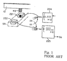
- Figure 1 illustrates the optical sensor matrix. Although the optical sensor matrix is used for eighty-eight black/ white keys, only one white key 10 is shown in figure 1.
- a shutter plate KS is attached to the lower surface of the white key 10, and is hatched in figure 1 for the purpose of discrimination.
- the prior art optical sensor matrix includes a light emitting sensor head 221, a light receiving sensor head 222, a light emitting diode array 224, a photo diode array 225 and bundles of optical fibers 226 and 227.
- the light emitting sensor head 221 and the light receiving sensor head 222 are fixed to a frame SB together with other light emitting sensor heads (not shown) and other photo detecting sensor heads 222 (not shown), and are spaced from one another.
- Twelve light emitting diodes form the array 224, and eight photo-detecting diodes form the other array 225.
- One of the light emitting diodes is connected through an optical fiber of the bundle 226 to the light emitting sensor head 221, and the light receiving sensor head 222 is connected through an optical fiber of the bundle 227 to one of the photo detecting diodes.
- Each of the light emitting diodes 224 is connected to eight optical fibers of the bundle 226, and twelve optical fibers of the bundle 227 are connected to each photo detecting diode 225. For this reason, eight light emitting sensor heads 221 concurrently radiate the eight optical beams, and the eight photo diodes 225 simultaneously receive the light transferred from the associated light receiving sensor heads 222 through the optical fibers 227.
- the combinations of the light emitting diodes 224 and the photo detecting diodes 225 are ninety-six, only eighty-eight combinations are used for the eight-eight black/ white keys.
- the light emitting diode 224 When the light emitting diode 224 is energized, the light emitting diode generates light. The light is propagated through the optical fiber 226 to the light emitting sensor head 221, and the light emitting sensor head 221 radiates a light beam to the light receiving sensor head 222 across the trajectory of the shutter plate KS. The light beam is 5 millimeter in diameter. The light receiving sensor head 222 receives the light beam, and the received light is propagated through the optical fiber 227 to the associated photo diode 225. The photo diode 225 converts the light to an electric signal Sa, and supplies the electric signal Sa to a controller (not shown).
- the electric signal Sa is representative of the amount of received light.
- a player is assumed to depress the white key 10.
- the white key 10 sinks toward the end position, and the shutter plate KS gradually intersects the light beam.
- the photo detecting diode 225 reduces the magnitude or the voltage of the electric signal Sa.
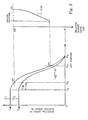
- the position-to-voltage converting characteristics of the prior art optical sensor matrix is represented by plots C1 in figure 2.
- the rest position of the white key 10 and the end position of the white key 10 are respectively abbreviated as “K R " and "K E " in figure 2.
- the shutter plate KS partially intersects the optical beam at the rest position K R , and the shutter plate KS is evacuated from the optical beam at position "K O ".
- the potential level of the electric signal Sa gradually falls from the rest position K R to the end position K E .
- the shutter plate KS allows part of the light beam to reach the light receiving sensor head 222, and the electric signal Sa still has a potential level.
- the shutter plate KS reaches the position K D , the shutter plate KS perfectly intersects the light beam, and the photo detecting diode 225 decreases the potential level of the electric signal Sa to zero.
- the white key 10 is moved between the rest position K R and the end position K E , and the photo detecting diode 225 varies the electric signal along the plots between the rest position K R and the end position K E .
- the position-to-voltage converting characteristics C1 is determined for a typical key during the fabrication of the automatic player piano, and pieces of control data information representative of the position-to-voltage converting characteristics C1 are stored in a non-volatile memory.
- the controller (not shown) determines the current key position on the basis of the position-to-voltage converting characteristics C1 during the recording, and digital codes representative of the pieces of music data information are produced from the current key position and the variance of the current key position.
- the performance reproduced in the playback is not consistent with the original performance. This is the problem inherent in the prior art automatic player piano.
- Each of the prior art optical key sensors was the combination of the light emitting diode 224, the optical fibers 226/ 227, the light emitting sensor head 221, the light receiving sensor head 222 and the photo detecting diode 225, and the position-to-voltage converting characteristics of one optical key sensor were usually different from the position-to-voltage converting characteristics of the others.
- the position-to-voltage converting characteristics were varied with time as indicated by plots C2 in figure 2. In this situation, if the controller determined the current key position on the basis of the position-to-voltage converting characteristics C1, the current key position unavoidably contained error, and the pieces of music data information did not exactly represent the original performance.
- the present inventors tried to rewrite the pieces of control data information from the position-to-voltage converting characteristics C1 to the position-to-voltage converting characteristics C2.
- the rewriting work was complicated, and only a few user could respond.
- the present inventors concluded that the approach was not feasible.
- the present inventors noticed that the position-to-voltage converting characteristics C2 had the profile analogous to that of the position-to-voltage converting characteristics C1. This meant that the position-to-voltage converting characteristics C2 were predictable. Otherwise, the electric power at the light emitting diodes 224 was made variable. If the position-to-voltage converting characteristics were varied from C1 to C2, increased electric power pushed up the position-to-voltage converting characteristics from C2 to C1.
- a musical instrument comprising plural manipulators movable within respective monitored ranges, and selectively manipulated by a player for specifying an attribute of sound and a position sensing device including plural sensors respectively provided for the plural manipulators and respectively creating the monitored ranges, a physical quantity in each of the monitored ranges being varied depending upon a current position of associated one of the manipulators and a controller storing a relation between the amount of the physical quantity and the current positions of the manipulators and determining the current position of each manipulated manipulator on the basis of the amount of physical quantity supplied from associated one of the plural sensors for determining the attribute of sound.
- a position sensing device comprising plural sensors respectively provided for plural manipulators and respectively creating monitored ranges where the plural manipulators are moved, a physical quantity in each of the monitored ranges being varied depending upon a current position of associated one of the manipulators and a controller storing a relation between the amount of the physical quantity and the current positions of the manipulators and determining the current position of each manipulated manipulator on the basis of the amount of physical quantity supplied from associated one of the plural sensors.
- a light-emitting controller for plural light-emitting elements, comprising a current-controlling circuit connected between a first source of power voltage and a power distribution line connected in parallel to the plural light-emitting elements and responsive to a first control signal for varying a resistance between the first source of power voltage and the power distribution line, a selector connected between the plural light-emitting elements and a second source of power voltage different in voltage level from the first source of power voltage, and responsive to a second control signal for sequentially connecting the plural light-emitting elements to the second source of power voltage and a signal generator supplying the first control signal and the second control signal to the current-controlling circuit and the selector so as to change the resistance optimum to selected one of the plural light-emitting elements.
- an automatic player piano embodying the present invention largely comprises an acoustic upright piano 1, a silent system 20 and an automatic playing system 30.
- a player fingers a piece of music on the acoustic upright piano 1, and the acoustic upright piano 1 generates acoustic sounds for the piece of music.
- the silent system 20 permits the player to finger the piece of music without the acoustic sounds, and generates electronic sounds in response to the fingering.
- the automatic playing system 30 records the performance, and reproduces the performance without the fingering of the player.
- word “front” is indicative of a relative position closer to a player than a "rear” position
- the direction between the front position and the rear position is modified by using word “longitudinal”.
- the lateral direction is perpendicular to the longitudinal direction.
- the acoustic upright piano 1 includes a keyboard 3.
- the keyboard 3 is placed on the key bed 4a, and includes black keys 3a and white keys 3b, a front rail 3c, a balance rail 3d and a back rail 3e.
- the front rail 3c, the balance rail 3d and the back rail 3e laterally extend in parallel on the key bed 4a, and are spaced from one another in the longitudinal direction.
- the black keys 3a and the white keys 3b are laid out on the well-known pattern, and are independently turnable around the balance rail 3d. Notes of a scale are assigned to the black/ white keys 3a/ 3b.
- Balance pins 3f keep the black keys 3a and the white keys 3b at the right positions. In this instance, eighty-eight black/ white keys 3a/ 3b are incorporated in the keyboard 3.
- the black keys 3a and the white keys 3b sink their rear ends on the back rail cloth adhered to the back rail 3e, and are staying in the rest positions, respectively.
- the black/ white keys 3a/ 3b are driven for rotation in the counter clockwise direction, and reach end positions, respectively.
- Capstan screws 3g project from the rear end portions of the black/ white keys 3a/ 3b.
- the acoustic upright piano 1 further comprises key action mechanisms 5, hammers 6, sets of strings 7 and damper mechanisms 8.
- the key action mechanisms 5 are associated with the black/ white keys 3a/ 3b, respectively, and the capstan screws 3g transfer the key motions to the associated key action mechanisms 5.
- the hammers 6 are connected to the key action mechanisms 5, respectively, and are driven for rotation. When the hammers 6 escape from a jack (not shown) forming a part of the associated key action mechanisms 5, the key action mechanisms 5 give the unique key touch to the fingers of the player.
- the hammer 6 strikes the associated set of strings 7, and the set of strings 7 generates the acoustic sound.
- a catcher projects from a butt of the hammer 6, and is linked with a bridle wire on a whippen assembly by means a bridle tape. After rebounding of the hammer 6 on the strings 7, the catcher is received by a back check block also projecting from the whippen, and the bridle tape makes the jack slide into the space beneath the butt.
- the damper mechanisms 8 are used for damping the vibrations of the strings 7.
- the damper mechanisms 8 are linked with the black/ white keys 3a/ 3b, respectively, and have respective damper heads.
- the damper heads When the associated black/ white keys 3a/ 3b are in the rest positions, the damper heads are held in contact with the sets of strings 7, and absorb the vibrations of the associated strings 7.
- a player depresses the black/ white key 3a/ 3b.
- the damper head is spaced from the associated set of strings 7, and the set of strings 7 is allowed to vibrate.
- the associated hammer 6 strikes the set of strings 7, and the strings 7 vibrate to generate the acoustic sound.
- the black/ white key 3a/ 3b starts to return toward the rest position.
- the damper head is brought into contact with the set of strings 7, again, and damps the vibrations.
- the silent system 20 includes a controller 100, a catcher stopper 20a and an actuator 20b.
- the controller 10 is shared between the silent system 20 and the automatic playing system 30, and will be described in detail hereinlater.
- the catcher stopper 20a is installed over the butt, and laterally extends.
- the catcher stopper 20a is connected to a rotatable shaft 20c of the actuator 20b, and the controller 100 energizes the actuator 20b so as to rotate the shaft 20c in one of the two directions.
- the catcher stopper 20a is rotated together with the shaft 20c, and is changed between a block position BP and a free position FP. In figure 3, the catcher stopper 20a is in the free position FP, and the catcher stopper 20a in the block position is drawn by broken lines.
- the catcher stopper 20a When the catcher stopper 20a reaches the block position BP, the catcher stopper 20a projects into the trajectory of the catcher.
- the catcher stopper 20a in the block position BP causes the catcher to rebound thereon between the escaping point and the striking point against the strings 7.
- the actuator 20b rotates the catcher stopper 20a in the opposite direction, the catcher stopper 20a reaches the free position FP, and is out of the trajectory of the catcher.
- the catcher stopper is not any obstacle, and the hammer 6 can strike the associated set of strings 7.
- the silent system 20 further includes plural key sensors 90.
- the plural key sensors 90 are associated with the black/ white keys 3a/ 3b, respectively, and the plural key sensors 90 are implemented by shutter plates 90a and an optical sensor matrix 90b.
- the shutter plates 90a are respectively attached to the lower surfaces of the black/ white keys 3a/ 3b, and the optical sensor matrix 90b is mounted on the key bed 4a.
- the optical sensor matrix 90b is similar in structure to the optical sensor matrix shown in figure 1, and light emitting diodes 90c, a bundle of optical fibers 90d, light emitting sensor heads 90e, light receiving sensor heads 90f, a bundle of optical fibers 90g and photo-detecting diodes 90h form in combination the optical sensor matrix 90b.
- the key sensors 90 detect current positions of the associated black/ white keys 3a/ 3b, and supply key position signals S1 representative of the current key positions to the controller 100.
- the controller 100 forms an audio signal S2 on the basis of the current key positions and variances thereof, and supplies the audio signal S2 to a headphone HH and/ or a speaker system SP.
- the headphone HH and/ or the speaker system SP generates electronic sound corresponding to the depressed keys 3a/ 3b.
- the key sensors 90 are shared between the silent system 20 and the automatic playing system 30 as will be described hereinbelow.
- the automatic playing system 30 includes the controller 100, the key sensors 90 and plural key actuators 30a.
- the key actuators 30a are respectively associated with the black/ white keys 3a/ 3b, and are mounted on the key bed 4a.
- the key actuator 30a has a solenoid 30b and a plunger 30c, and the plunger 30c is retracted in the solenoid 30b. When the solenoid 30b is energized, the plunger 30c projects from the solenoid 30b, and pushes up the associated black/ white key 3a/ 3b.
- the key sensors 90 reports the current key positions through the key position signals S1 to the controller 100, and the controller 100 produces music data codes representative of the performance on the basis of the key position signals S1 and the variance thereof.
- the music data codes are stored in a suitable memory such as, for example, a floppy disk 110 (see figure 4).
- the original performance is reproduced in a playback mode.
- the controller 100 reads out the music data codes from the memory 110, and produces a driving voltage signals S3 on the basis of the music data codes.
- the driving voltage signals S3 are selectively supplied to the key actuators 30a, and the plungers 30c move the black/ white keys 3a/ 3b.
- FIG 4 illustrates the controller 100.
- the controller 100 includes a central processing unit 100a, a read only memory 100b such as a flush memory, a random access memory 100c and a shared bus 100d.
- the central processing unit 100a, the read only memory 100b and the random access memory 100c are respectively abbreviated as "CPU", "ROM” and "RAM” in figure 4.
- the central processing unit 100a may be implemented by a microprocessor.
- the read only memory 100b stores programmed instructions, and various tables are defined in the read only memory 100b.
- the music data codes are temporarily stored in the random access memory 100c, and calculating results are also temporarily stored in the random access memory 100c.
- the central processing unit 100a, the read only memory 100b and the random access memory 100c are connected to the shared bus 100d.
- the central processing unit 100a sequentially fetches the programmed instructions through the shared bus 100d, and executes them for given jobs.
- the central processing unit 100c defines tables in the random access memory device during the execution of
- the controller 100 further includes a switch panel 100e, and a push button switch SW1 is incorporated in the switch panel 100e together with other switches (not shown).
- the switch panel 100e is connected to the shared bus 100d, and user gives instructions from the switch panel 100e through the shared bus 100d to the central processing unit 100a. The user shifts the catcher stopper 20a between the block position BP and the free position FP by using the push button switch SW1.
- the controller 100 further includes a maintenance switch panel 100f, and is also connected to the shared bus 100d.
- the maintenance switch panel 100f is provided inside the piano case, and is not exposed to the outside. For this reason, assembly workers and tuners usually manipulate switches SW2, SW3 and SW4 on the maintenance switch panel 100f. If the switches SW2, SW3 and SW4 are manipulated, the maximum voltage level L M2 , the voltage level L R2 at the rest position and the voltage level L E2 are measured.
- the controller 100 further includes a tone generator 100g. which is also connected to the shared bus 100d.
- the central processing unit 100a supplies the pieces of music data information representative of a key code, velocity, key-on event, key-off event and a release rate to the tone generator, and the tone generator 100g produces a tone signal on the basis of the pieces of music data information.
- the tone generator 100g has sixteen channels, and each tone signal is formed through one of the channels. When the piece of music data information representative of the key-on event is supplied to the channel, the channel imparts parts of envelope called as "attack”, “decay” and “sustain” to the tone signal. The channel controls the amplitude and the damping rate depending upon the velocity and the release rate, respectively.
- the tone signal is mixed with other tone signals, and these tone signals form the audio signal S2.
- the tone generator 100g concurrently produces sixteen tone signals at the maximum, and the headphone HH and/ or the speaker system SP can generate sixteen electronic sounds.
- the audio signal S2 is supplied to the headphone HH and/ or the speaker system SP, and the electronic sounds are radiated from the headphone HH and/ or the speaker system SP.
- the tone color may be like an acoustic piano sound.
- the controller 100 further includes an amplifier 100h, an analog-to-digital converter 100j and an LED driver 100k.
- the amplifier 100h is connected between the photo detecting diodes 90h and the analog-to-digital converter 100j, and the analog-to-digital converter 100j is connected to the shared bus 100d.
- the LED driver 100k is connected between the shared bus 100d and the light emitting diodes 90c.
- the central processing unit 100a instructs the LED driver 100k to sequentially energize the light emitting diodes 90c.
- the key position signals S1 are supplied through the amplifier 100h to the analog-to-digital converter 100j, and the analog-to-digital converter 100j converts the key position signals S to digital key position signals S4.
- the optical sensor matrix 90 has twelve light emitting diodes 90c and eight photo detecting diodes 90h.
- the twelve light emitting diodes 90c and the eight photo detecting diodes 90h results in ninety-six combinations, and eighty-eight combinations are assigned to the eighty-eight black/ white keys 3a/ 3b.
- the central processing unit 100a can specify the black/ white keys 3a/ 3b just radiated with the light beams.
- Each of the twelve light emitting diodes is connected to eight light emitting sensor heads 90e through the optical fibers 90d, and the light beams are concurrently radiated from the eight light emitting sensor heads 90e toward the associated light receiving sensor heads 90f.
- the eighty-eight light receiving sensor heads 90f are divided into twelve sensor head groups, and each sensor head group, i.e., the eight light receiving sensor heads 90f are respectively connected to the eight photo-detecting diodes 90h.
- the LED driver 100k sequentially energizes the twelve light emitting diodes 90c, and each light emitting diode 90c causes the eight light emitting sensor heads 90e to radiate the light beams toward the associated light receiving sensor heads 90f. For this reason, the eighty-eight black/ white keys 3a/ 3b are radiated with the light beams eight by eight.
- the radiation with the eight light beams is hereinbelow referred to as "scanning".
- the eight light receiving sensor heads 90f concurrently receive the light beams, and the eight optical fibers 90g propagate the light to the eight photo detecting diodes 90h.
- the eight key position signals S1 are concurrently supplied through the amplifier 100h to the analog-to-digital converter 100j.
- the eight key position signals S1 is divided into two groups, and the four key position signals S1 are concurrently converted to the four digital key position signals S4. For this reason, the central processing unit 100a fetches the four digital key position signals S4 twice a scanning.
- the central processing unit 100a repeatedly fetches the digital key position signals S4 representative of the current positions of the eighty-eight black/ white keys 3a/ 3b, and determines the key code, the velocity, the key-on event, the key-off event and the release rate for each of the depressed keys 3a/ 3b.
- the central processing unit 100a produces the music data codes from the pieces of music data information representative of the key code, the velocity, the key-on event, the key-of event and the release rate.
- the music data codes are formatted in accordance with the MIDI (Musical Instrument Digital Interface) standards.
- the controller 100 further includes a floppy disk driver 100m and a driver circuit 100n for the key actuators 30a.
- the music data codes are transferred to the floppy disk driver 100m in the recording mode, and the floppy disk driver 100m stores the music data codes in the floppy disk 110.
- the floppy disk driver 100m reads out the music data codes from the floppy disk 110, and transfers them to the random access memory 100c.
- the music data codes are temporarily stored in the random access memory 100c.
- the music data codes are sequentially read out from the random access memory 100c, and the central processing unit 100a instructs the driver circuit 100n to selectively supply the driving voltage signal S3 to the key actuators 30a.
- the solenoid 30b is energized with the driving voltage signal S3, and the plunger 30c projects from the solenoid 30b.
- the plunger 30c pushes up the associated black/ white key 3a/ 3b, and moves it without player's fingering.
- the black/ white key 3a/ 3b is moved in the predetermined range such as, for example, 10 millimeters
- the shutter plate 90a is also moved in the predetermined range such as, for example, 5 millimeters.
- the controller 100 further includes an angle detector 100p and a driver circuit 100q for the actuator 20b.
- the driver circuit 100q supplies electric power to the actuator 20b, and changes the polarity depending upon the rotating direction of the shaft 20c.
- the angle detector 100p monitors the catcher stopper 20a, and reports the current angular position of the catcher stopper 20a to the central processing unit 100a. When the catcher stopper 20a enters the block position BP or the free position FP, the central processing unit 100a instructs the driver circuit 100q to stop the rotation.
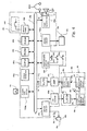
- Figure 5 illustrates the circuit configuration of the LED driver 100k, the optical sensor matrix 90, the amplifier 100h and the analog-to-digital converter 100j.
- the light emitting diodes 90c are individually labeled with 224-1, 224-2, 224-3, ... .., and the photo-detecting diodes 90h are individually labeled with 225-1, 225-2, ... and 225-8.
- the amplifier 100h has eight amplifier units 226-1, 226-2... 226-8, and the eight amplifier units 226-1 to 226-8 are similar in circuit configuration to one another. For this reason, only one amplifier unit 226-1 is detailed hereinbelow.
- An operational amplifier 226a and three resistors 226b, 226c and 226d form in combination the amplifier unit 226-1.
- the resistor 226b is connected between the anode of the associated photo detecting diode 225-1 and the ground line.
- the anode of the photo detecting diode 225-1 is connected to the inverted node of the operational amplifier 226a, and the ground line is connected through the resistor 226c to the non-inverted node of the operational amplifier 226a.
- the resistor 226d is connected between the output node AN1 of the operational amplifier 226a to the inverted node.
- photocurrent flows through the resistor 226b, and the resistor 226b converts the photo current to a voltage.
- the voltage is applied to the non-inverted node of the operational amplifier 226a.
- the operational amplifier 226a amplifies the voltage level at the non-inverted node, and the resistors 226c and 226d determine the gain of the operational amplifier 226a.
- the output voltage of the operational amplifier 226a is supplied from the output node AN1 to the analog-to-digital converter 100j.
- the LED driver 100k is broken down into a current controlling circuit 100k1 and a selector 100k2.
- the current controlling circuit 100k1 includes p-channel enhancement type field effect transistors 103/ 104, n-p-n bipolar transistors 108/ 109 and resistors 101/ 102/ 105/ 106/ 107.
- the resistor 105, the series combination of the n-p-n bipolar transistor 103 and the resistor 106 and the series combination of the n-p-n bipolar transistor 104 and the resistor 107 are connected in parallel between a power supply line PW and a power distribution line PW2.
- the power distribution line PW2 is connected to the anodes of the light emitting diodes 224-1, 224-2, 224-3, ... .
- the resistor 101 is associated with the p-channel enhancement type field effect transistor 103, and is connected between the source node and the gate electrode.
- the resistor 102 is associated with the other p-channel enhancement type field effect transistor 104, and is connected between the source node and the gate electrode.
- the n-p-n bipolar transistors 108/ 109 are connected between the gate electrodes of the p-channel enhancement type field effect transistors 103/ 104 and the ground line.
- the central processing unit 100a supplies control signals S A12 and S A13 to the base nodes of the n-p-n bipolar transistors 108/ 109, respectively.
- the resistors 105/ 106/ 107 are 330 ohms, 220 ohms and 150 ohms, respectively.
- the central processing unit 100a selectively changes the control signals S A12 and S A13 between the ground level and a positive high level.
- the central processing unit 100a keeps both control signals S A12 and S A13 in the ground level, the n-p-n bipolar transistors 108/ 109 are turned off, and cause the gate electrodes of the p-channel enhancement type field effect transistors 103/ 104 to be equal in voltage level to the source nodes.
- the p-channel enhancement type field effect transistors 103/ 104 are turned off, and the electric current flows form the power supply line PW1 through the resistor 105 to the power distribution line PW2.
- the central processing unit 100a changes the control signal S A12 to the positive high level, the n-p-n bipolar transistor 108 turns on, and electric current flows through the resistor 101 and the n-p-n bipolar transistor 108 to the ground line.
- the resistor 101 causes the gate electrode of the p-channel enhancement type field effect transistor 103 to be lower than the source node thereof, and the p-channel enhancement type field effect transistor 103 turns on.
- another current path is offered in parallel to the resistor 105, and the electric current flows through the p-channel enhancement type field effect transistor 103 and the resistor 106 into the power distribution line PW2.
- the total resistance against the electric current is equivalent to 132 ohms, i.e., 330// 220.
- the central processing unit 100a respectively changes the control signal lines S A12 and S A13 to the ground level and the positive high level, the other n-p-n bipolar transistor 109 turns on, and, accordingly, the associated p-channel enhancement type field effect transistor 104 turns on.
- the n-p-n bipolar transistor 108 and, accordingly, the p-channel enhancement type field effect transistor 103 turn off
- the p-channel enhancement type field effect transistor 104 and the resistor 107 offers another current path to the power distribution line PW2.
- the total resistance against the current is equal to 103 ohms.
- both n-p-n bipolar transistors 108/ 109 turn on, and, accordingly, both p-channel enhancement type field effect transistors 103/ 104 turn on, and the electric current flows through the three current paths into the power distribution line PW2.
- the total resistance against the electric current is equal to 70 ohms.
- the central processing unit 100a selectively changes the control signals S A12 and S A13 to the positive high level, and varies the amount of current flowing into the power distribution line PW2.
- the selector 100k2 includes series combinations of resistors 110-1/ 110-2/ 110-3/ ... . and n-p-n bipolar transistors 111-1/ 111-2/ 111-3/ ...
- the series combinations are connected between the cathodes of the light emitting diodes 224-1/ 224-2/ 224-3/.. and the ground line.
- the central processing unit 100a has twelve control signal lines S LED connected to the base nodes of the n-p-n bipolar transistors 111-1, 111-2, 111-3 ... . , and sequentially changes the twelve control signal lines S LED to the positive high level.
- the n-p-n bipolar transistors 111-1, 111-2, 111-3, ... sequentially turn on, and the light emitting diodes 224-1, 224-2, 224-3, ... are also sequentially energized so as to emit the light beams.
- An ideal operational amplifier has an inverted input node and a noninverted input node imaginary short-circuited.
- the photo detecting diode 90h is assumed to be associated with the ideal operational amplifier. While any light does not fall into the photo-detecting diode 90h, any electric current does not flow, and the input voltage and, accordingly, the output voltage are zero.
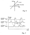
- the actual operational amplifiers 226a has input voltage-to-output voltage characteristics indicated by plots PL10 (see figure 6). Vin and Vout represent the input voltage and the output voltage, respectively.
- the plots PL10 does not pass the origin, and the output voltage Vout has a positive value.
- the positive value is the offset voltage.
- the output voltage Vout at the output node AN1 AN2/... / AN8 contains the offset voltage at all times.
- the central processing unit 100a In order to exactly determine the current key position on the basis of the key position signal S1, it is necessary to eliminate the offset voltage from the output voltage Vout. In this instance, the central processing unit 100a periodically measures the offset voltage as shown in figure 7. The central processing unit 100a sequentially changes the control signals S LED1 , S LED2 , ... and S LED12 to the positive high level. The control signals S LED1 , S LED2 , ... and S LED12 causes the light-emitting diodes 224-1, 224-2, 224-3, ... to radiate the light beams, respectively, as described hereinbefore. The time period for sequentially illuminating the light-emitting diodes 90c is hereinbelow referred to as "scanning cycle".
- the control signals S LED1 , S LED2 , ... and S LED12 have the pulse width of 0.01 millisecond, and each control signal S LED1 , S LED2 , ... or S LED12 regularly rises at intervals of 0.12 milliseconds. In this instance, the regular scanning cycle is 0.12 milliseconds.
- the central processing unit 100a prolongs the interval once a minute. Namely, an irregular scanning cycle of 0.13 milliseconds is inserted one a minute. This means that all the central processing unit 100a extinguishes all the light-emitting diodes 90c for 0.01 millisecond.
- the central processing unit 100a While the central processing unit 100a is extinguishing all the light-emitting diodes 90c, the input voltage Vin is zero, and the operational amplifiers 226a change the key position signals S1 to values of the offset voltage.
- the key position signals S1 are converted to the digital key position signals S4, and the central processing unit 100a fetches the digital key position signals S4 representative of the values of the offset voltage.
- the central processing unit 100a transfers the digital key position signals S4 to the random access memory 100c, and stores them in the random access memory 100c as pieces of control data information representative of the current values of the offset voltage.
- the central processing unit 100a renews the pieces of control data information at the intervals of one minute.
- the central processing unit 100a While the central processing unit 100a is recording a performance, the central processing unit 100a subtracts the current value of the offset voltage from the value of the digital key position signal S4 representative of the current key position. Thus, the central processing unit 100a compensates the digital key position signals S4 for the offset voltage of the associated operational amplifiers 226a, and produces the pieces of music data information free from the offset voltage.
- the current key position is, by way of example, used for calculation of a velocity of a depressed key 3a/ 3b.
- the central processing unit 100a requires two current key positions spaced apart on the trajectory of the depressed key, a time at which the one of the current key positions was measured and a time at which the other current key position was measured.
- the insertion of irregular scanning cycle delays the regular scanning cycles by 0.01 millisecond.
- the central processing unit 100a requires 0.12 milliseconds for the data acquisition from the eighty-eight black/ white keys 3a/ 3b. The delay of 0.01 millisecond is ignoreable.
- the central processing unit 100a may correct the time in the calculation of the velocity.
- the manufacturer determines initial position-to-voltage converting characteristics C1 (see figure 2) for each of the key sensors 90, and stores pieces of control data information representative of the initial characteristics C1 in the read only memory 100b or the flush memory.
- the manufacturer Before mounting the keyboard 3 on the key bed 4a, the manufacturer places the optical sensor matrix 90 on the key bed 4a, and attaches the shutter plates 90a to the piano case.
- the manufacturer moves the shutter plates 90a between the light-emitting sensor heads 90e and the associated light receiving sensor heads 90f.
- the shutter plates 90a are moved at intervals of 0.15 millimeter. In other words, the shutter plates 90a offer forth-seven sampling points on the trajectory of 7 millimeters.
- the central processing unit 100a instructs the LED driver 100k to sequentially radiate the light-emitting diodes 90c at every sampling point, and fetches the digital key position signals S4.
- the central processing unit 100a stores the values at every sampling point in the random access memory 100c.
- the central processing unit 100a calculates the moving average for smoothing.
- the central processing unit 100a reads out the values from the certain sampling point, the previous three sampling points and the next three sampling points, and the read-out values are averaged. As a result, the noise is eliminated from the sampling values. If the sampling values are saturated, the central processing unit 100a appropriately changes the control signals S A12 and S A13 so as to reduce the electric current supplied to the light-emitting diodes 90c. Thus, the central processing unit 100a optimizes the amount of electric current flowing into the light-emitting diodes 90c. If the maximum sampling value is out of the allowable range or the position-to-voltage converting characteristics C1 are quite different, the optical sensor matrix possibly contains defective part or parts, and the manufacturer replaces the defective parts with new parts.
- the central processing unit selects a sampling point at the mid point of the stroke of the shutter plate 90a as follows.
- the central processing unit 100a firstly determines the highest sampling point with the maximum value and the lowest sampling point with the minimum value. Subsequently, the central processing unit 100a selects the first sampling point, which has the sampling value 15 percent larger than the minimum sampling value. The central processing unit 100a further selects the second sampling point, which has the sampling value 15 percent smaller than the maximum sampling value.
- the central processing unit 100a calculates the mean value between the first sampling point and the second sampling point, and selects a sampling point with the sampling value closest to the mean value. The selected sampling point is the sampling point at the mid point.
- the central processing unit 100a selects sixty-four sampling points around the selected sampling point, and the sampling values at the sixty-four sampling points are stored in the read only memory 100b.
- the selected sampling value at the mid sampling point is stored at AD[31], and the sixty-four sampling values are stored at AD[0] to AD[63].
- the maximum sampling value is also stored in the read only memory 100b as the maximum level L M1 .
- the black/ white keys 3a/ 3b are depressed, and the shutter plates 90a reach the peripheries of the light beams. If the black/ white keys 3a/ 3b are further depressed, the sampling values are decreased.
- the central processing unit 100a determines the key position with the sampling value immediately before the decrease to be an open position Ko (see figure 2) for the black/ white key 3a/ 3b.
- the open positions Ko are stored in the read only memory 100b.
- the black/ white keys 3a/ 3b are further depressed.
- the central processing unit 100a determines the key position to be a perfectly closed position K D of the black/ white key 3a/ 3b.
- the perfectly closed position K D is stored in the read only memory 100b.
- the central processing unit 100a determines the position-to-voltage converting characteristics C1, the values of the maximum level LM1, the open positions Ko and the perfectly closed positions K D for all the black/ white keys 3a/ 3b.
- the manufacturer attaches the shutter plates 90a to the lower surfaces of the black/ white keys 3a/ 3b, and the keyboard 3 is mounted on the key bed 4a.
- the light-emitting diodes 90c vary the intensity due to the aged deterioration.
- the aged deterioration is observed during the fabrication of the automatic player piano. For this reason, the manufacturer manually regulates the position-to-voltage converting characteristics at the final stage of the fabrication as follows.
- the operator lifts up the keyboard 3, and the shutter plates 90a are sufficiently spaced from the light-emitting sensor heads 90e and the light receiving sensor heads 90f.
- the operator pushes the switch SW2.
- the central processing unit 100a instructs the LED driver 100k to sequentially energize the twelve light-emitting diodes 90c.
- the light-emitting sensor heads 90e respectively radiate the light beams to the light-receiving sensor heads 90f without any intersection of the shutter plates 90a, and the photo-detecting diodes 90h convert the received light to the key position signals S1.
- the key position signals S1 and, accordingly, the digital key position signals S4 are indicative of the maximum level L M2 .
- the values of the maximum level L M2 are stored in the random access memory 100c.
- the operator mounts the keyboard 3 on the key bed 4a, again, and pushes the switch SW3.
- the central processing unit 100a instructs the LED driver 100k to sequentially energize the twelve light-emitting diodes 90c, again.
- the digital key position signals S4 are indicative of the voltage levels L R2 at the rest position K R .
- the voltage levels L R2 are stored in the random access memory 100c.
- the operator depresses the eighty-eight black/ white keys 3a/ 3b, and the eighty-eight black/ white keys 3a/ 3b reach the end positions K E .
- the operator pushes the switch SW4.
- central processing unit 100a instructs the LED driver 100k to sequentially energize the twelve light-emitting diodes 90c, and the digital key position signals S4 are indicative of the voltage levels L E2 at the end positions K E .
- the voltage levels L E2 are stored in the random access memory 100c.
- the central processing unit 100a determines a rest position level L R1 and an end position level L E1 on the position-to-voltage converting characteristics C1.
- L E1 L E2 ⁇ L M1 / L M2
- the black/ white keys 3a/ 3b are equal in stroke to one another, and, accordingly, the shutter plates 90a are also equal to one another.
- the central processing unit 100a may determine only the end position level L E1 , because the central processing unit 100 can calculate the other levels.
- the central processing unit 100a may determine the rest position level L R1 instead of the end position level L E1 .
- the central processing unit 100a produces a linearization table represented by plots PL20.
- the abscissa is indicative of the shutter position
- the axis of coordinates is indicative of a relative output level SAR of the key sensors 90.
- the relative output level SAR has unit value equal to the quotient of a division where the difference between the binary value L R2 and binary value at the key position the K D i.e., zero, is divided by 256.
- the binary key position signal S4 reaches zero, the relative output level SAR is zero.
- the relative output level SAR is 256 at the binary value L R2 .
- the shutter position is determined on the basis of the position-to-voltage converting characteristics C1.
- the shutter position is zero at the end position K E and 255 at the rest position K R .
- the plots PL20 is obtained through the linear interpolation between the sampling points for the position-to-voltage converting characteristics.
- the shutter position is to be simply increased with respect to the relative output level SAR, there is a possibility that the interpolation results in decrease of the shutter position inversely to the relative output level SAR due to the noise imperfectly eliminated.
- a shutter position SPx is assumed to be decreased inversely to the relative position SARx.
- the central processing unit 100a assumes the shutter position SPx to be equal to the previous shutter position SPx-1 at the relative output level SARx-1, which is one point before the corresponding relative output level SARx.
- the central processing unit 100a instructs the LED driver 100k to sequentially energize the light-emitting diodes 90c, and the key sensors 90 check the eighty-eight black/ white keys 3a/ 3b to see whether they change the key positions.
- the key sensors 90 supply the key position signals S1 through the amplifier 100h to the analog-to-digital converter 100j, and the analog-to-digital converter 100j are fetched by the central processing unit 100a.
- the central processing unit 100a compensates the binary value of the digital key position signal S4 for the offset voltage.
- the central processing unit 100a determines the current key position of each black/ white key 3a/ 3b as follows.
- the relative output level SAR is rounded, and is represented by an integer.
- the central processing unit 100a checks the linearization table so as to determine the shutter position, i.e., the current key position.
- the central processing unit 100a stores the current key positions in the random access memory device 100c, and produces the music data codes from the current key positions and the variances of the current key positions.
- Japanese Patent Publication of Unexamined Application No. 9-54584 discloses how the central processing unit 100a determines a note-on timing, i.e., the key-on timing, a note-off timing, i.e., the key-off timing and the velocity. For this reason, no further description is hereinbelow incorporated for the sake of simplicity.
- the maximum level LM2, the output level L R2 at the rest position and the output level L E2 at the end position are stored in the memory 100b before the delivery from the factory. They may be renewed during the tuning work. In this instance, the voltage level L R2 is automatically renewed in the usual usage.
- the central processing unit 100a periodically checks the binary values of the digital key position signals S4 representative of the rest positions K R of the black/ white keys 3a/ 3b to see whether or not the digital key position signals S4 vary the binary values. If one of the key sensors 90 keeps the digital key position signal S4 at a certain binary value for a predetermined time period, the central processing unit 100a determines the certain binary value to indicate the current rest position K R , and changes the voltage level L R2 .
- the controller 100 according to the present invention can cope with the variation of the light intensity of the light-emitting diodes 90c in a short span.
- the light-emitting diodes 90c emit the light
- the light-emitting sensor heads 90e radiate the light beams to the light-receiving sensor heads 90f.
- Each of the light-receiving sensor heads 90f transfers the received light to the associated photo-detecting diode 90h, and the received light is converted to the key position signal S1.
- the amount of light received is converted to the magnitude of the key position signal S1.
- the reliability of the key position signal S1 is dependent on the stability of the light intensity of the light emitted from the light-emitting diodes 90c under the circumstances.
- the electric power-to-light converting characteristics of the light-emitting diodes 90c are unavoidably dispersed.
- the light-emitting diodes 90c do not always achieve a target light intensity under a well-regulated electric current.
- the amplified key position signal S1 exceeds the upper limit of the analog-to-digital converter 100j, and the central processing unit 100a can not exactly determine the current key position.
- the current controlling circuit 100k1 is well regulated to the light-emitting diode 90c with the maximum luminous efficiency, it is possible to restrict the amplified key position signals S1 under the upper limit of the analog-to-digital converter 100j.
- such a regulation is undesirable for the light-emitting diode 90c with the minimum luminous efficiency. Because, the key sensors 90 do not sufficiently swing the key position signals S1. This results in a low resolution of the current key position.
- the controller 100 stores optimum light-emitting conditions of each light-emitting diode 90c in the random access memory 100c.
- a combination of the control signals SA12/ SA13 define the light-emitting conditions.
- the central processing unit 100a selects one of the n-p-n bipolar transistors 111-1/ 111-2/ 111-3/ ... and, accordingly, the associated light-emitting diode 110-1/ 110-2/ 110-3/... .
- the central processing unit 100a reads out the optimum electric conditions from the random access memory 100c, and changes the control signals SA12/ SA13.
- every light-emitting diode 90c radiates the light under the optimum electric conditions, and the key sensors 90 swing the key position signals S1 in the full dynamic range of the analog-to-digital converter 100j without exceeding it.
- the light-emitting conditions for each light-emitting diode 90c is automatically regulated as follows.
- the central processing unit 100a monitors each of the digital key position signals S4 at all times to see whether or not the binary value thereof reaches the maximum binary value of the analog-to-digital converter 100j. If the binary value of a digital key position signal S4 reaches the maximum binary value, the central processing unit 100a chances the light-emitting conditions.
- the light-emitting conditions are assumed to require both control signals SA12/ SA13 at the positive high level for the optimum light-emitting conditions.
- the central processing unit 100a changes the optimum light-emitting conditions where one of the control signals SA12/ SA13 is changed to the inactive ground level.
- the associated digital key position signals S4 swings the binary values under the upper limit.
- the central processing unit 100a employs the different binary value as the output level L R2 .
- the central processing unit 100a changes the light-emitting conditions in such a manner as to decrease the equivalent resistance. As a result, the electric current is increased, and the output level L R2 is pulled up.
- the controller 100 automatically regulates the output level L R2 and the optimum light-emitting conditions.
- the central processing unit 100a stores the relation between the relative output level SAR and the current shutter/ key position, and determines the current shutter/ key position on the basis of the relative output level SAR. For this reason, the regulation of the optimum light emitting conditions does not have serious influence on the current shutter/ key position.
- the position sensing device according to the present invention is applied to the automatic player piano for exactly detecting the current key positions.
- the position sensing device is not limited to the detection of the current key positions.
- Various kinds of manipulators are incorporated in musical instruments, and the current position of the manipulator usually has influences on the sounds.
- the position sensing device according to the present invention enhances the reliability of the current position, and is desirable for the manipulators.
- the position sensing device is, by way of example, provided to foot pedals, i.e., a soft pedal and a damper pedal of an automatic player piano or a silent piano.
- the amount of light is the physical quantity varied together with the position of the manipulator.
- the black/ white keys 3a/ 3b serve as plural manipulators.
- the monitored range is equivalent to a region from Ko to K D .
- Attribute of sound means a note and loudness.
- the key sensors 90, the LED driver 100k, the amplifier 100h, the analog-to-digital converter 100j, the central processing unit 100a, the read only memory 100b and the random access memory 100c as a whole constitute the position sensing device.
- the current controlling circuit 100k1 serves as a variable power supply means.
- a first instruction is represented by the control signals S A12 / S A13 .
- a second instruction is represented by the control signals S LED .
- the position sensing device may be incorporated in a silent piano (see U.S. Patent No. 5,374,775, by way of example).
- the silent system may be eliminated from the automatic player piano according to the present invention.
- the position sensing device may be incorporated in an electric keyboard for electronically generating sounds.
- the current controlling circuit 100k1 may have more than two series combinations of the p-channel enhancement type field effect transistors 103/ 104 and the resistors 106/ 107 associated with the n-p-n bipolar transistors 108/ 109.
- the invention relates to a musical instrument comprising, plural manipulators (3a/3b) and a position sensing device including plural sensors (90), and a controller (100) characterized in that said controller (100) stores a relation (C1/ C2/ PL20) between the amount of a physical quantity and current positions of said manipulators.
Abstract
Description
- This invention relates to a musical instrument and, more particularly, to a keyboard musical instrument of the type having key sensors for detecting the current positions of keys, a position sensing device and a light-emitting controller both incorporated therein.
- An automatic player piano is an example of the keyboard musical instrument. The automatic player piano records a performance on the keyboard, and stores the performance in a suitable memory in the form of pieces of music data information. When a user requests the automatic player piano to reproduce the performance, the pieces of music data information are read out from the memory, and selectively energizes key actuators so as to move the black/ white keys without fingering. Thus, the automatic player piano has two modes of operation, i.e., the recording mode and the playback mode.
- Key sensors are provided under the black/ white keys, and convert the current key positions to positional signals. The positional signals are supplied to a controller, and the controller extracts the pieces of music data information to be required for the playback from the positional signals and variance thereof. Thus, the key sensors are important components of the automatic player piano.
- An optical key sensor is popular to the automatic player piano. A light-emitting diode is paired with a photo-detecting diode, and produces a light beam across a trajectory of a shutter plate attached to the black/ white key. If the optical key sensors are individually installed for the black/ white keys, the installation makes the price of the automatic player piano go up.
- An optical sensor matrix was proposed in Japanese Patent Application No. 7-270332, which was published, as Japanese Patent Publication of Unexamined Application No. 9-54584. Twelve light emitting diodes and eight photo diodes form in combination the optical sensor matrix for the keyboards, which usually consists of eighty-eight black/ white keys.
- Figure 1 illustrates the optical sensor matrix. Although the optical sensor matrix is used for eighty-eight black/ white keys, only one
white key 10 is shown in figure 1. A shutter plate KS is attached to the lower surface of thewhite key 10, and is hatched in figure 1 for the purpose of discrimination. The prior art optical sensor matrix includes a lightemitting sensor head 221, a lightreceiving sensor head 222, a lightemitting diode array 224, aphoto diode array 225 and bundles ofoptical fibers emitting sensor head 221 and the lightreceiving sensor head 222 are fixed to a frame SB together with other light emitting sensor heads (not shown) and other photo detecting sensor heads 222 (not shown), and are spaced from one another. Twelve light emitting diodes form thearray 224, and eight photo-detecting diodes form theother array 225. One of the light emitting diodes is connected through an optical fiber of thebundle 226 to the lightemitting sensor head 221, and the lightreceiving sensor head 222 is connected through an optical fiber of thebundle 227 to one of the photo detecting diodes. Each of thelight emitting diodes 224 is connected to eight optical fibers of thebundle 226, and twelve optical fibers of thebundle 227 are connected to eachphoto detecting diode 225. For this reason, eight lightemitting sensor heads 221 concurrently radiate the eight optical beams, and the eightphoto diodes 225 simultaneously receive the light transferred from the associated lightreceiving sensor heads 222 through theoptical fibers 227. Although the combinations of thelight emitting diodes 224 and thephoto detecting diodes 225 are ninety-six, only eighty-eight combinations are used for the eight-eight black/ white keys. - When the
light emitting diode 224 is energized, the light emitting diode generates light. The light is propagated through theoptical fiber 226 to the lightemitting sensor head 221, and the lightemitting sensor head 221 radiates a light beam to the lightreceiving sensor head 222 across the trajectory of the shutter plate KS. The light beam is 5 millimeter in diameter. The lightreceiving sensor head 222 receives the light beam, and the received light is propagated through theoptical fiber 227 to the associatedphoto diode 225. Thephoto diode 225 converts the light to an electric signal Sa, and supplies the electric signal Sa to a controller (not shown). - The electric signal Sa is representative of the amount of received light. A player is assumed to depress the
white key 10. Thewhite key 10 sinks toward the end position, and the shutter plate KS gradually intersects the light beam. As a result, the amount of received light is decreased, and, accordingly, thephoto detecting diode 225 reduces the magnitude or the voltage of the electric signal Sa. - The position-to-voltage converting characteristics of the prior art optical sensor matrix is represented by plots C1 in figure 2. The rest position of the
white key 10 and the end position of thewhite key 10 are respectively abbreviated as "KR" and "KE" in figure 2. The shutter plate KS partially intersects the optical beam at the rest position KR, and the shutter plate KS is evacuated from the optical beam at position "KO". The potential level of the electric signal Sa gradually falls from the rest position KR to the end position KE. When thewhite key 10 reaches the end position KE, the shutter plate KS allows part of the light beam to reach the lightreceiving sensor head 222, and the electric signal Sa still has a potential level. If the shutter plate KS reaches the position KD, the shutter plate KS perfectly intersects the light beam, and thephoto detecting diode 225 decreases the potential level of the electric signal Sa to zero. Thewhite key 10 is moved between the rest position KR and the end position KE, and thephoto detecting diode 225 varies the electric signal along the plots between the rest position KR and the end position KE. - The position-to-voltage converting characteristics C1 is determined for a typical key during the fabrication of the automatic player piano, and pieces of control data information representative of the position-to-voltage converting characteristics C1 are stored in a non-volatile memory. The controller (not shown) determines the current key position on the basis of the position-to-voltage converting characteristics C1 during the recording, and digital codes representative of the pieces of music data information are produced from the current key position and the variance of the current key position. However, the performance reproduced in the playback is not consistent with the original performance. This is the problem inherent in the prior art automatic player piano.
- It is therefore an important object of the present invention to provide an automatic player piano, which faithfully reproduces an original performance.
- It is also an important object of the present invention to provide a position sensing device, which exactly determines the current position of a moving object such as, for example, a black/ white key.
- The present inventors contemplated the problem inherent in the prior art automatic player piano, and noticed that the
light emitting diodes 224, theoptical fibers 226/ 227 and thephoto diodes 225 had individualities. The individualities were influential on the position-to-voltage converting characteristics. Each of the prior art optical key sensors was the combination of thelight emitting diode 224, theoptical fibers 226/ 227, the lightemitting sensor head 221, the lightreceiving sensor head 222 and thephoto detecting diode 225, and the position-to-voltage converting characteristics of one optical key sensor were usually different from the position-to-voltage converting characteristics of the others. Moreover, the position-to-voltage converting characteristics were varied with time as indicated by plots C2 in figure 2. In this situation, if the controller determined the current key position on the basis of the position-to-voltage converting characteristics C1, the current key position unavoidably contained error, and the pieces of music data information did not exactly represent the original performance. - Firstly, the present inventors tried to rewrite the pieces of control data information from the position-to-voltage converting characteristics C1 to the position-to-voltage converting characteristics C2. However, the rewriting work was complicated, and only a few user could respond. The present inventors concluded that the approach was not feasible.
- Second, the present inventors tried to map the position-to-voltage converting characteristics C1 to the position-to-voltage converting characteristics C2, because the variance of voltage from LR1 to LR1' = LR2 and from LE1 to LE1' =LE2 were easily measured. However, the profile between LR1' and LE1' was different from the profile between LR2 and LE2. Even though the position-to-voltage converting characteristics C1 were exactly mapped, the mapped characteristics did not give the exact current positions to the controller.
- The present inventors noticed that the position-to-voltage converting characteristics C2 had the profile analogous to that of the position-to-voltage converting characteristics C1. This meant that the position-to-voltage converting characteristics C2 were predictable. Otherwise, the electric power at the
light emitting diodes 224 was made variable. If the position-to-voltage converting characteristics were varied from C1 to C2, increased electric power pushed up the position-to-voltage converting characteristics from C2 to C1. - In accordance with one aspect of the present invention, there is provided a musical instrument comprising plural manipulators movable within respective monitored ranges, and selectively manipulated by a player for specifying an attribute of sound and a position sensing device including plural sensors respectively provided for the plural manipulators and respectively creating the monitored ranges, a physical quantity in each of the monitored ranges being varied depending upon a current position of associated one of the manipulators and a controller storing a relation between the amount of the physical quantity and the current positions of the manipulators and determining the current position of each manipulated manipulator on the basis of the amount of physical quantity supplied from associated one of the plural sensors for determining the attribute of sound.
- In accordance with another aspect of the present invention, there is provided a position sensing device comprising plural sensors respectively provided for plural manipulators and respectively creating monitored ranges where the plural manipulators are moved, a physical quantity in each of the monitored ranges being varied depending upon a current position of associated one of the manipulators and a controller storing a relation between the amount of the physical quantity and the current positions of the manipulators and determining the current position of each manipulated manipulator on the basis of the amount of physical quantity supplied from associated one of the plural sensors.
- In accordance with yet another aspect of the present invention, there is provided a light-emitting controller for plural light-emitting elements, comprising a current-controlling circuit connected between a first source of power voltage and a power distribution line connected in parallel to the plural light-emitting elements and responsive to a first control signal for varying a resistance between the first source of power voltage and the power distribution line, a selector connected between the plural light-emitting elements and a second source of power voltage different in voltage level from the first source of power voltage, and responsive to a second control signal for sequentially connecting the plural light-emitting elements to the second source of power voltage and a signal generator supplying the first control signal and the second control signal to the current-controlling circuit and the selector so as to change the resistance optimum to selected one of the plural light-emitting elements.
- The features and advantages of the keyboard musical instrument and the position sensing device will be more clearly understood from the following description taken in conjunction with the accompanying drawings in which:
- Fig. 1 is a schematic view showing the prior art optical sensor matrix;
- Fig. 2 is a graph showing the position-to-voltage converting characteristics varied with time and a rectifying curve according to the present invention;
- Fig. 3 is a schematic view showing the structure of an automatic player piano according to the present invention;
- Fig. 4 is a block diagram showing the circuit arrangement of a controller incorporated in the automatic player piano;
- Fig. 5 is a circuit diagram showing the circuit configuration of an LED driver, light-emitting diodes, photo-detecting diodes and an amplifier;
- Fig. 6 is a graph showing input voltage-to-output voltage characteristics of an operational amplifier incorporated in the amplifier; and
- Fig. 7 is a timing chart showing control signals for sequentially selecting the light-emitting diodes.
-
- Referring to figure 3 of the drawings, an automatic player piano embodying the present invention largely comprises an
acoustic upright piano 1, asilent system 20 and anautomatic playing system 30. A player fingers a piece of music on theacoustic upright piano 1, and theacoustic upright piano 1 generates acoustic sounds for the piece of music. Thesilent system 20 permits the player to finger the piece of music without the acoustic sounds, and generates electronic sounds in response to the fingering. Theautomatic playing system 30 records the performance, and reproduces the performance without the fingering of the player. In the following description, word "front" is indicative of a relative position closer to a player than a "rear" position, and the direction between the front position and the rear position is modified by using word "longitudinal". The lateral direction is perpendicular to the longitudinal direction. - The
acoustic upright piano 1 includes akeyboard 3. Thekeyboard 3 is placed on thekey bed 4a, and includesblack keys 3a andwhite keys 3b, a front rail 3c, abalance rail 3d and aback rail 3e. The front rail 3c, thebalance rail 3d and theback rail 3e laterally extend in parallel on thekey bed 4a, and are spaced from one another in the longitudinal direction. Theblack keys 3a and thewhite keys 3b are laid out on the well-known pattern, and are independently turnable around thebalance rail 3d. Notes of a scale are assigned to the black/white keys 3a/ 3b.Balance pins 3f keep theblack keys 3a and thewhite keys 3b at the right positions. In this instance, eighty-eight black/white keys 3a/ 3b are incorporated in thekeyboard 3. - While any force is not exerted on the
black keys 3a and thewhite keys 3b, theblack keys 3a and thewhite keys 3b sink their rear ends on the back rail cloth adhered to theback rail 3e, and are staying in the rest positions, respectively. When a player depresses the black/white keys 3a/ 3b, the black/white keys 3a/ 3b are driven for rotation in the counter clockwise direction, and reach end positions, respectively. Capstan screws 3g project from the rear end portions of the black/white keys 3a/ 3b. - The
acoustic upright piano 1 further comprises key action mechanisms 5, hammers 6, sets ofstrings 7 anddamper mechanisms 8. The key action mechanisms 5 are associated with the black/white keys 3a/ 3b, respectively, and thecapstan screws 3g transfer the key motions to the associated key action mechanisms 5. Thehammers 6 are connected to the key action mechanisms 5, respectively, and are driven for rotation. When thehammers 6 escape from a jack (not shown) forming a part of the associated key action mechanisms 5, the key action mechanisms 5 give the unique key touch to the fingers of the player. Thehammer 6 strikes the associated set ofstrings 7, and the set ofstrings 7 generates the acoustic sound. Though not shown in the drawings, a catcher projects from a butt of thehammer 6, and is linked with a bridle wire on a whippen assembly by means a bridle tape. After rebounding of thehammer 6 on thestrings 7, the catcher is received by a back check block also projecting from the whippen, and the bridle tape makes the jack slide into the space beneath the butt. - The
damper mechanisms 8 are used for damping the vibrations of thestrings 7. Thedamper mechanisms 8 are linked with the black/white keys 3a/ 3b, respectively, and have respective damper heads. When the associated black/white keys 3a/ 3b are in the rest positions, the damper heads are held in contact with the sets ofstrings 7, and absorb the vibrations of the associated strings 7. A player depresses the black/white key 3a/ 3b. Then, the damper head is spaced from the associated set ofstrings 7, and the set ofstrings 7 is allowed to vibrate. The associatedhammer 6 strikes the set ofstrings 7, and thestrings 7 vibrate to generate the acoustic sound. When the player releases the black/white key 3a/ 3b, the black/white key 3a/ 3b starts to return toward the rest position. The damper head is brought into contact with the set ofstrings 7, again, and damps the vibrations. - The
silent system 20 includes acontroller 100, acatcher stopper 20a and anactuator 20b. Thecontroller 10 is shared between thesilent system 20 and theautomatic playing system 30, and will be described in detail hereinlater. Thecatcher stopper 20a is installed over the butt, and laterally extends. Thecatcher stopper 20a is connected to arotatable shaft 20c of theactuator 20b, and thecontroller 100 energizes theactuator 20b so as to rotate theshaft 20c in one of the two directions. Thecatcher stopper 20a is rotated together with theshaft 20c, and is changed between a block position BP and a free position FP. In figure 3, thecatcher stopper 20a is in the free position FP, and thecatcher stopper 20a in the block position is drawn by broken lines. - When the
catcher stopper 20a reaches the block position BP, thecatcher stopper 20a projects into the trajectory of the catcher. Thecatcher stopper 20a in the block position BP causes the catcher to rebound thereon between the escaping point and the striking point against thestrings 7. On the other hand, when theactuator 20b rotates thecatcher stopper 20a in the opposite direction, thecatcher stopper 20a reaches the free position FP, and is out of the trajectory of the catcher. The catcher stopper is not any obstacle, and thehammer 6 can strike the associated set ofstrings 7. - The
silent system 20 further includes pluralkey sensors 90. The pluralkey sensors 90 are associated with the black/white keys 3a/ 3b, respectively, and the pluralkey sensors 90 are implemented byshutter plates 90a and anoptical sensor matrix 90b. Theshutter plates 90a are respectively attached to the lower surfaces of the black/white keys 3a/ 3b, and theoptical sensor matrix 90b is mounted on thekey bed 4a. Theoptical sensor matrix 90b is similar in structure to the optical sensor matrix shown in figure 1, andlight emitting diodes 90c, a bundle ofoptical fibers 90d, light emitting sensor heads 90e, light receivingsensor heads 90f, a bundle ofoptical fibers 90g and photo-detectingdiodes 90h form in combination theoptical sensor matrix 90b. Thekey sensors 90 detect current positions of the associated black/white keys 3a/ 3b, and supply key position signals S1 representative of the current key positions to thecontroller 100. Thecontroller 100 forms an audio signal S2 on the basis of the current key positions and variances thereof, and supplies the audio signal S2 to a headphone HH and/ or a speaker system SP. The headphone HH and/ or the speaker system SP generates electronic sound corresponding to thedepressed keys 3a/ 3b. Thekey sensors 90 are shared between thesilent system 20 and theautomatic playing system 30 as will be described hereinbelow. - The
automatic playing system 30 includes thecontroller 100, thekey sensors 90 and pluralkey actuators 30a. Thekey actuators 30a are respectively associated with the black/white keys 3a/ 3b, and are mounted on thekey bed 4a. Thekey actuator 30a has asolenoid 30b and aplunger 30c, and theplunger 30c is retracted in thesolenoid 30b. When thesolenoid 30b is energized, theplunger 30c projects from thesolenoid 30b, and pushes up the associated black/white key 3a/ 3b. - While the
automatic playing system 30 is recording a performance on thekeyboard 3, thekey sensors 90 reports the current key positions through the key position signals S1 to thecontroller 100, and thecontroller 100 produces music data codes representative of the performance on the basis of the key position signals S1 and the variance thereof. The music data codes are stored in a suitable memory such as, for example, a floppy disk 110 (see figure 4). The original performance is reproduced in a playback mode. Thecontroller 100 reads out the music data codes from thememory 110, and produces a driving voltage signals S3 on the basis of the music data codes. The driving voltage signals S3 are selectively supplied to thekey actuators 30a, and theplungers 30c move the black/white keys 3a/ 3b. - Figure 4 illustrates the
controller 100. Thecontroller 100 includes acentral processing unit 100a, a read onlymemory 100b such as a flush memory, arandom access memory 100c and a sharedbus 100d. Thecentral processing unit 100a, the read onlymemory 100b and therandom access memory 100c are respectively abbreviated as "CPU", "ROM" and "RAM" in figure 4. Thecentral processing unit 100a may be implemented by a microprocessor. The read onlymemory 100b stores programmed instructions, and various tables are defined in the read onlymemory 100b. The music data codes are temporarily stored in therandom access memory 100c, and calculating results are also temporarily stored in therandom access memory 100c. Thecentral processing unit 100a, the read onlymemory 100b and therandom access memory 100c are connected to the sharedbus 100d. Thecentral processing unit 100a sequentially fetches the programmed instructions through the sharedbus 100d, and executes them for given jobs. Thecentral processing unit 100c defines tables in the random access memory device during the execution of the programmed instructions. - The
controller 100 further includes aswitch panel 100e, and a push button switch SW1 is incorporated in theswitch panel 100e together with other switches (not shown). Theswitch panel 100e is connected to the sharedbus 100d, and user gives instructions from theswitch panel 100e through the sharedbus 100d to thecentral processing unit 100a. The user shifts thecatcher stopper 20a between the block position BP and the free position FP by using the push button switch SW1. - The
controller 100 further includes amaintenance switch panel 100f, and is also connected to the sharedbus 100d. Themaintenance switch panel 100f is provided inside the piano case, and is not exposed to the outside. For this reason, assembly workers and tuners usually manipulate switches SW2, SW3 and SW4 on themaintenance switch panel 100f. If the switches SW2, SW3 and SW4 are manipulated, the maximum voltage level LM2, the voltage level LR2 at the rest position and the voltage level LE2 are measured. - The
controller 100 further includes a tone generator 100g. which is also connected to the sharedbus 100d. Thecentral processing unit 100a supplies the pieces of music data information representative of a key code, velocity, key-on event, key-off event and a release rate to the tone generator, and thetone generator 100g produces a tone signal on the basis of the pieces of music data information. Thetone generator 100g has sixteen channels, and each tone signal is formed through one of the channels. When the piece of music data information representative of the key-on event is supplied to the channel, the channel imparts parts of envelope called as "attack", "decay" and "sustain" to the tone signal. The channel controls the amplitude and the damping rate depending upon the velocity and the release rate, respectively. The tone signal is mixed with other tone signals, and these tone signals form the audio signal S2. Thus, thetone generator 100g concurrently produces sixteen tone signals at the maximum, and the headphone HH and/ or the speaker system SP can generate sixteen electronic sounds. The audio signal S2 is supplied to the headphone HH and/ or the speaker system SP, and the electronic sounds are radiated from the headphone HH and/ or the speaker system SP. The tone color may be like an acoustic piano sound. - The
controller 100 further includes anamplifier 100h, an analog-to-digital converter 100j and anLED driver 100k. Theamplifier 100h is connected between thephoto detecting diodes 90h and the analog-to-digital converter 100j, and the analog-to-digital converter 100j is connected to the sharedbus 100d. TheLED driver 100k is connected between the sharedbus 100d and thelight emitting diodes 90c. Thecentral processing unit 100a instructs theLED driver 100k to sequentially energize thelight emitting diodes 90c. The key position signals S1 are supplied through theamplifier 100h to the analog-to-digital converter 100j, and the analog-to-digital converter 100j converts the key position signals S to digital key position signals S4. - The
optical sensor matrix 90 has twelve light emittingdiodes 90c and eightphoto detecting diodes 90h. The twelvelight emitting diodes 90c and the eightphoto detecting diodes 90h results in ninety-six combinations, and eighty-eight combinations are assigned to the eighty-eight black/white keys 3a/ 3b. Thecentral processing unit 100a can specify the black/white keys 3a/ 3b just radiated with the light beams. Each of the twelve light emitting diodes is connected to eight light emitting sensor heads 90e through theoptical fibers 90d, and the light beams are concurrently radiated from the eight light emitting sensor heads 90e toward the associated light receivingsensor heads 90f. The eighty-eight light receivingsensor heads 90f are divided into twelve sensor head groups, and each sensor head group, i.e., the eight light receivingsensor heads 90f are respectively connected to the eight photo-detectingdiodes 90h. - The
LED driver 100k sequentially energizes the twelvelight emitting diodes 90c, and eachlight emitting diode 90c causes the eight light emitting sensor heads 90e to radiate the light beams toward the associated light receivingsensor heads 90f. For this reason, the eighty-eight black/white keys 3a/ 3b are radiated with the light beams eight by eight. The radiation with the eight light beams is hereinbelow referred to as "scanning". The eight light receivingsensor heads 90f concurrently receive the light beams, and the eightoptical fibers 90g propagate the light to the eightphoto detecting diodes 90h. Thus, the eight key position signals S1 are concurrently supplied through theamplifier 100h to the analog-to-digital converter 100j. However, only four analog-to-digital converting units are incorporated in the analog-to-digital converter 100j. The eight key position signals S1 is divided into two groups, and the four key position signals S1 are concurrently converted to the four digital key position signals S4. For this reason, thecentral processing unit 100a fetches the four digital key position signals S4 twice a scanning. - The
central processing unit 100a repeatedly fetches the digital key position signals S4 representative of the current positions of the eighty-eight black/white keys 3a/ 3b, and determines the key code, the velocity, the key-on event, the key-off event and the release rate for each of thedepressed keys 3a/ 3b. Thecentral processing unit 100a produces the music data codes from the pieces of music data information representative of the key code, the velocity, the key-on event, the key-of event and the release rate. In this instance, the music data codes are formatted in accordance with the MIDI (Musical Instrument Digital Interface) standards. - The
controller 100 further includes afloppy disk driver 100m and adriver circuit 100n for thekey actuators 30a. The music data codes are transferred to thefloppy disk driver 100m in the recording mode, and thefloppy disk driver 100m stores the music data codes in thefloppy disk 110. On the other hand, thefloppy disk driver 100m reads out the music data codes from thefloppy disk 110, and transfers them to therandom access memory 100c. The music data codes are temporarily stored in therandom access memory 100c. The music data codes are sequentially read out from therandom access memory 100c, and thecentral processing unit 100a instructs thedriver circuit 100n to selectively supply the driving voltage signal S3 to thekey actuators 30a. Thesolenoid 30b is energized with the driving voltage signal S3, and theplunger 30c projects from thesolenoid 30b. Theplunger 30c pushes up the associated black/white key 3a/ 3b, and moves it without player's fingering. In this instance, the black/white key 3a/ 3b is moved in the predetermined range such as, for example, 10 millimeters, and theshutter plate 90a is also moved in the predetermined range such as, for example, 5 millimeters. - The
controller 100 further includes anangle detector 100p and a driver circuit 100q for theactuator 20b. The driver circuit 100q supplies electric power to theactuator 20b, and changes the polarity depending upon the rotating direction of theshaft 20c. Theangle detector 100p monitors thecatcher stopper 20a, and reports the current angular position of thecatcher stopper 20a to thecentral processing unit 100a. When thecatcher stopper 20a enters the block position BP or the free position FP, thecentral processing unit 100a instructs the driver circuit 100q to stop the rotation. - Figure 5 illustrates the circuit configuration of the
LED driver 100k, theoptical sensor matrix 90, theamplifier 100h and the analog-to-digital converter 100j. Thelight emitting diodes 90c are individually labeled with 224-1, 224-2, 224-3, ... .., and the photo-detectingdiodes 90h are individually labeled with 225-1, 225-2, ... and 225-8. - The
amplifier 100h has eight amplifier units 226-1, 226-2... 226-8, and the eight amplifier units 226-1 to 226-8 are similar in circuit configuration to one another. For this reason, only one amplifier unit 226-1 is detailed hereinbelow. An operational amplifier 226a and threeresistors resistor 226b is connected between the anode of the associated photo detecting diode 225-1 and the ground line. The anode of the photo detecting diode 225-1 is connected to the inverted node of the operational amplifier 226a, and the ground line is connected through theresistor 226c to the non-inverted node of the operational amplifier 226a. Theresistor 226d is connected between the output node AN1 of the operational amplifier 226a to the inverted node. When the light beam is incident on the associated photo detecting diode 225-1, photocurrent flows through theresistor 226b, and theresistor 226b converts the photo current to a voltage. The voltage is applied to the non-inverted node of the operational amplifier 226a. The operational amplifier 226a amplifies the voltage level at the non-inverted node, and theresistors - The
LED driver 100k is broken down into a current controlling circuit 100k1 and a selector 100k2. The current controlling circuit 100k1 includes p-channel enhancement typefield effect transistors 103/ 104, n-p-nbipolar transistors 108/ 109 andresistors 101/ 102/ 105/ 106/ 107. Theresistor 105, the series combination of the n-p-nbipolar transistor 103 and the resistor 106 and the series combination of the n-p-nbipolar transistor 104 and theresistor 107 are connected in parallel between a power supply line PW and a power distribution line PW2. The power distribution line PW2 is connected to the anodes of the light emitting diodes 224-1, 224-2, 224-3, ... . Theresistor 101 is associated with the p-channel enhancement typefield effect transistor 103, and is connected between the source node and the gate electrode. Similarly, theresistor 102 is associated with the other p-channel enhancement typefield effect transistor 104, and is connected between the source node and the gate electrode. The n-p-nbipolar transistors 108/ 109 are connected between the gate electrodes of the p-channel enhancement typefield effect transistors 103/ 104 and the ground line. Thecentral processing unit 100a supplies control signals SA12 and SA13 to the base nodes of the n-p-nbipolar transistors 108/ 109, respectively. In this instance, theresistors 105/ 106/ 107 are 330 ohms, 220 ohms and 150 ohms, respectively. - The
central processing unit 100a selectively changes the control signals SA12 and SA13 between the ground level and a positive high level. When thecentral processing unit 100a keeps both control signals SA12 and SA13 in the ground level, the n-p-nbipolar transistors 108/ 109 are turned off, and cause the gate electrodes of the p-channel enhancement typefield effect transistors 103/ 104 to be equal in voltage level to the source nodes. As a result, the p-channel enhancement typefield effect transistors 103/ 104 are turned off, and the electric current flows form the power supply line PW1 through theresistor 105 to the power distribution line PW2. If thecentral processing unit 100a changes the control signal SA12 to the positive high level, the n-p-nbipolar transistor 108 turns on, and electric current flows through theresistor 101 and the n-p-nbipolar transistor 108 to the ground line. Theresistor 101 causes the gate electrode of the p-channel enhancement typefield effect transistor 103 to be lower than the source node thereof, and the p-channel enhancement typefield effect transistor 103 turns on. As a result, another current path is offered in parallel to theresistor 105, and the electric current flows through the p-channel enhancement typefield effect transistor 103 and the resistor 106 into the power distribution line PW2. The total resistance against the electric current is equivalent to 132 ohms, i.e., 330// 220. - When the
central processing unit 100a respectively changes the control signal lines SA12 and SA13 to the ground level and the positive high level, the other n-p-nbipolar transistor 109 turns on, and, accordingly, the associated p-channel enhancement typefield effect transistor 104 turns on. The n-p-nbipolar transistor 108 and, accordingly, the p-channel enhancement typefield effect transistor 103 turn off The p-channel enhancement typefield effect transistor 104 and theresistor 107 offers another current path to the power distribution line PW2. The total resistance against the current is equal to 103 ohms. - When the
central processing unit 100a changes both control signal lines SA12 and SA13 to the positive high level, both n-p-nbipolar transistors 108/ 109 turn on, and, accordingly, both p-channel enhancement typefield effect transistors 103/ 104 turn on, and the electric current flows through the three current paths into the power distribution line PW2. The total resistance against the electric current is equal to 70 ohms. Thus, thecentral processing unit 100a selectively changes the control signals SA12 and SA13 to the positive high level, and varies the amount of current flowing into the power distribution line PW2. - The selector 100k2 includes series combinations of resistors 110-1/ 110-2/ 110-3/ ... . and n-p-n bipolar transistors 111-1/ 111-2/ 111-3/ ... The series combinations are connected between the cathodes of the light emitting diodes 224-1/ 224-2/ 224-3/.. and the ground line. The
central processing unit 100a has twelve control signal lines SLED connected to the base nodes of the n-p-n bipolar transistors 111-1, 111-2, 111-3 ... . , and sequentially changes the twelve control signal lines SLED to the positive high level. The n-p-n bipolar transistors 111-1, 111-2, 111-3, ... sequentially turn on, and the light emitting diodes 224-1, 224-2, 224-3, ... are also sequentially energized so as to emit the light beams. - An ideal operational amplifier has an inverted input node and a noninverted input node imaginary short-circuited. The
photo detecting diode 90h is assumed to be associated with the ideal operational amplifier. While any light does not fall into the photo-detectingdiode 90h, any electric current does not flow, and the input voltage and, accordingly, the output voltage are zero. However, the actual operational amplifiers 226a has input voltage-to-output voltage characteristics indicated by plots PL10 (see figure 6). Vin and Vout represent the input voltage and the output voltage, respectively. The plots PL10 does not pass the origin, and the output voltage Vout has a positive value. The positive value is the offset voltage. The output voltage Vout at the output node AN1 AN2/... / AN8 contains the offset voltage at all times. - In order to exactly determine the current key position on the basis of the key position signal S1, it is necessary to eliminate the offset voltage from the output voltage Vout. In this instance, the
central processing unit 100a periodically measures the offset voltage as shown in figure 7. Thecentral processing unit 100a sequentially changes the control signals SLED1, SLED2 , ... and SLED12 to the positive high level. The control signals SLED1, SLED2 , ... and SLED12 causes the light-emitting diodes 224-1, 224-2, 224-3, ... to radiate the light beams, respectively, as described hereinbefore. The time period for sequentially illuminating the light-emittingdiodes 90c is hereinbelow referred to as "scanning cycle". The control signals SLED1, SLED2 , ... and SLED12 have the pulse width of 0.01 millisecond, and each control signal SLED1, SLED2 , ... or SLED12 regularly rises at intervals of 0.12 milliseconds. In this instance, the regular scanning cycle is 0.12 milliseconds. Thecentral processing unit 100a prolongs the interval once a minute. Namely, an irregular scanning cycle of 0.13 milliseconds is inserted one a minute. This means that all thecentral processing unit 100a extinguishes all the light-emittingdiodes 90c for 0.01 millisecond. While thecentral processing unit 100a is extinguishing all the light-emittingdiodes 90c, the input voltage Vin is zero, and the operational amplifiers 226a change the key position signals S1 to values of the offset voltage. The key position signals S1 are converted to the digital key position signals S4, and thecentral processing unit 100a fetches the digital key position signals S4 representative of the values of the offset voltage. Thecentral processing unit 100a transfers the digital key position signals S4 to therandom access memory 100c, and stores them in therandom access memory 100c as pieces of control data information representative of the current values of the offset voltage. Thus, thecentral processing unit 100a renews the pieces of control data information at the intervals of one minute. - While the
central processing unit 100a is recording a performance, thecentral processing unit 100a subtracts the current value of the offset voltage from the value of the digital key position signal S4 representative of the current key position. Thus, thecentral processing unit 100a compensates the digital key position signals S4 for the offset voltage of the associated operational amplifiers 226a, and produces the pieces of music data information free from the offset voltage. - The current key position is, by way of example, used for calculation of a velocity of a
depressed key 3a/ 3b. Thecentral processing unit 100a requires two current key positions spaced apart on the trajectory of the depressed key, a time at which the one of the current key positions was measured and a time at which the other current key position was measured. The insertion of irregular scanning cycle delays the regular scanning cycles by 0.01 millisecond. However, thecentral processing unit 100a requires 0.12 milliseconds for the data acquisition from the eighty-eight black/white keys 3a/ 3b. The delay of 0.01 millisecond is ignoreable. Of course, thecentral processing unit 100a may correct the time in the calculation of the velocity. - The manufacturer determines initial position-to-voltage converting characteristics C1 (see figure 2) for each of the
key sensors 90, and stores pieces of control data information representative of the initial characteristics C1 in the read onlymemory 100b or the flush memory. - Before mounting the
keyboard 3 on thekey bed 4a, the manufacturer places theoptical sensor matrix 90 on thekey bed 4a, and attaches theshutter plates 90a to the piano case. The manufacturer moves theshutter plates 90a between the light-emitting sensor heads 90e and the associated light receivingsensor heads 90f. Theshutter plates 90a are moved at intervals of 0.15 millimeter. In other words, theshutter plates 90a offer forth-seven sampling points on the trajectory of 7 millimeters. Thecentral processing unit 100a instructs theLED driver 100k to sequentially radiate the light-emittingdiodes 90c at every sampling point, and fetches the digital key position signals S4. Thecentral processing unit 100a stores the values at every sampling point in therandom access memory 100c. - Subsequently, the
central processing unit 100a calculates the moving average for smoothing. When thecentral processing unit 100a calculates the moving average at a certain sampling point, thecentral processing unit 100a reads out the values from the certain sampling point, the previous three sampling points and the next three sampling points, and the read-out values are averaged. As a result, the noise is eliminated from the sampling values. If the sampling values are saturated, thecentral processing unit 100a appropriately changes the control signals SA12 and SA13 so as to reduce the electric current supplied to the light-emittingdiodes 90c. Thus, thecentral processing unit 100a optimizes the amount of electric current flowing into the light-emittingdiodes 90c. If the maximum sampling value is out of the allowable range or the position-to-voltage converting characteristics C1 are quite different, the optical sensor matrix possibly contains defective part or parts, and the manufacturer replaces the defective parts with new parts. - Subsequently, the central processing unit selects a sampling point at the mid point of the stroke of the
shutter plate 90a as follows. Thecentral processing unit 100a firstly determines the highest sampling point with the maximum value and the lowest sampling point with the minimum value. Subsequently, thecentral processing unit 100a selects the first sampling point, which has the sampling value 15 percent larger than the minimum sampling value. Thecentral processing unit 100a further selects the second sampling point, which has the sampling value 15 percent smaller than the maximum sampling value. Thecentral processing unit 100a calculates the mean value between the first sampling point and the second sampling point, and selects a sampling point with the sampling value closest to the mean value. The selected sampling point is the sampling point at the mid point. - Subsequently, the
central processing unit 100a selects sixty-four sampling points around the selected sampling point, and the sampling values at the sixty-four sampling points are stored in the read onlymemory 100b. The selected sampling value at the mid sampling point is stored at AD[31], and the sixty-four sampling values are stored at AD[0] to AD[63]. The maximum sampling value is also stored in the read onlymemory 100b as the maximum level LM1. - The black/
white keys 3a/ 3b are depressed, and theshutter plates 90a reach the peripheries of the light beams. If the black/white keys 3a/ 3b are further depressed, the sampling values are decreased. Thecentral processing unit 100a determines the key position with the sampling value immediately before the decrease to be an open position Ko (see figure 2) for the black/white key 3a/ 3b. The open positions Ko are stored in the read onlymemory 100b. - The black/
white keys 3a/ 3b are further depressed. When the sampling value reaches zero, thecentral processing unit 100a determines the key position to be a perfectly closed position KD of the black/white key 3a/ 3b. The perfectly closed position KD is stored in the read onlymemory 100b. The above-described steps are repeated, and thecentral processing unit 100a determines the position-to-voltage converting characteristics C1, the values of the maximum level LM1, the open positions Ko and the perfectly closed positions KD for all the black/white keys 3a/ 3b. Subsequently, the manufacturer attaches theshutter plates 90a to the lower surfaces of the black/white keys 3a/ 3b, and thekeyboard 3 is mounted on thekey bed 4a. - The light-emitting
diodes 90c vary the intensity due to the aged deterioration. The aged deterioration is observed during the fabrication of the automatic player piano. For this reason, the manufacturer manually regulates the position-to-voltage converting characteristics at the final stage of the fabrication as follows. - First, the operator lifts up the
keyboard 3, and theshutter plates 90a are sufficiently spaced from the light-emitting sensor heads 90e and the light receivingsensor heads 90f. The operator pushes the switch SW2. Then, thecentral processing unit 100a instructs theLED driver 100k to sequentially energize the twelve light-emittingdiodes 90c. The light-emitting sensor heads 90e respectively radiate the light beams to the light-receivingsensor heads 90f without any intersection of theshutter plates 90a, and the photo-detectingdiodes 90h convert the received light to the key position signals S1. The key position signals S1 and, accordingly, the digital key position signals S4 are indicative of the maximum level LM2. The values of the maximum level LM2 are stored in therandom access memory 100c. - Subsequently, the operator mounts the
keyboard 3 on thekey bed 4a, again, and pushes the switch SW3. Then, thecentral processing unit 100a instructs theLED driver 100k to sequentially energize the twelve light-emittingdiodes 90c, again. The digital key position signals S4 are indicative of the voltage levels LR2 at the rest position KR. The voltage levels LR2 are stored in therandom access memory 100c. - Finally, the operator depresses the eighty-eight black/
white keys 3a/ 3b, and the eighty-eight black/white keys 3a/ 3b reach the end positions KE. The operator pushes the switch SW4. Then,central processing unit 100a instructs theLED driver 100k to sequentially energize the twelve light-emittingdiodes 90c, and the digital key position signals S4 are indicative of the voltage levels LE2 at the end positions KE. The voltage levels LE2 are stored in therandom access memory 100c. - The
central processing unit 100a determines a rest position level LR1 and an end position level LE1 on the position-to-voltage converting characteristics C1. The rest position level LR1 and the end position level LE1 are given aswhite keys 3a/ 3b are equal in stroke to one another, and, accordingly, theshutter plates 90a are also equal to one another. Thecentral processing unit 100a may determine only the end position level LE1, because thecentral processing unit 100 can calculate the other levels. Thecentral processing unit 100a may determine the rest position level LR1 instead of the end position level LE1. - Subsequently, the
central processing unit 100a produces a linearization table represented by plots PL20. The abscissa is indicative of the shutter position, and the axis of coordinates is indicative of a relative output level SAR of thekey sensors 90. The relative output level SAR has unit value equal to the quotient of a division where the difference between the binary value LR2 and binary value at the key position the KD i.e., zero, is divided by 256. When the binary key position signal S4 reaches zero, the relative output level SAR is zero. The relative output level SAR is 256 at the binary value LR2. The shutter position is determined on the basis of the position-to-voltage converting characteristics C1. The shutter position is zero at the end position KE and 255 at the rest position KR. The plots PL20 is obtained through the linear interpolation between the sampling points for the position-to-voltage converting characteristics. Although the shutter position is to be simply increased with respect to the relative output level SAR, there is a possibility that the interpolation results in decrease of the shutter position inversely to the relative output level SAR due to the noise imperfectly eliminated. A shutter position SPx is assumed to be decreased inversely to the relative position SARx. Thecentral processing unit 100a assumes the shutter position SPx to be equal to the previous shutter position SPx-1 at the relative output level SARx-1, which is one point before the corresponding relative output level SARx. - While a player is performing a tune on the
keyboard 3, thecentral processing unit 100a instructs theLED driver 100k to sequentially energize the light-emittingdiodes 90c, and thekey sensors 90 check the eighty-eight black/white keys 3a/ 3b to see whether they change the key positions. Thekey sensors 90 supply the key position signals S1 through theamplifier 100h to the analog-to-digital converter 100j, and the analog-to-digital converter 100j are fetched by thecentral processing unit 100a. Thecentral processing unit 100a compensates the binary value of the digital key position signal S4 for the offset voltage. Thecentral processing unit 100a determines the current key position of each black/white key 3a/ 3b as follows. First, thecentral processing unit 100a determines the relative output level SAR ascentral processing unit 100a checks the linearization table so as to determine the shutter position, i.e., the current key position. - The
central processing unit 100a stores the current key positions in the randomaccess memory device 100c, and produces the music data codes from the current key positions and the variances of the current key positions. Japanese Patent Publication of Unexamined Application No. 9-54584 discloses how thecentral processing unit 100a determines a note-on timing, i.e., the key-on timing, a note-off timing, i.e., the key-off timing and the velocity. For this reason, no further description is hereinbelow incorporated for the sake of simplicity. - The maximum level LM2, the output level LR2 at the rest position and the output level LE2 at the end position are stored in the
memory 100b before the delivery from the factory. They may be renewed during the tuning work. In this instance, the voltage level LR2 is automatically renewed in the usual usage. Thecentral processing unit 100a periodically checks the binary values of the digital key position signals S4 representative of the rest positions KR of the black/white keys 3a/ 3b to see whether or not the digital key position signals S4 vary the binary values. If one of thekey sensors 90 keeps the digital key position signal S4 at a certain binary value for a predetermined time period, thecentral processing unit 100a determines the certain binary value to indicate the current rest position KR, and changes the voltage level LR2. As a result, thecontroller 100 according to the present invention can cope with the variation of the light intensity of the light-emittingdiodes 90c in a short span. - As described hereinbefore, the light-emitting
diodes 90c emit the light, and the light-emitting sensor heads 90e radiate the light beams to the light-receivingsensor heads 90f. Each of the light-receivingsensor heads 90f transfers the received light to the associated photo-detectingdiode 90h, and the received light is converted to the key position signal S1. Thus, the amount of light received is converted to the magnitude of the key position signal S1. The reliability of the key position signal S1 is dependent on the stability of the light intensity of the light emitted from the light-emittingdiodes 90c under the circumstances. However, the electric power-to-light converting characteristics of the light-emittingdiodes 90c are unavoidably dispersed. This means that the light-emittingdiodes 90c do not always achieve a target light intensity under a well-regulated electric current. When the light intensity is too large, the amplified key position signal S1 exceeds the upper limit of the analog-to-digital converter 100j, and thecentral processing unit 100a can not exactly determine the current key position. Of course, if the current controlling circuit 100k1 is well regulated to the light-emittingdiode 90c with the maximum luminous efficiency, it is possible to restrict the amplified key position signals S1 under the upper limit of the analog-to-digital converter 100j. However, such a regulation is undesirable for the light-emittingdiode 90c with the minimum luminous efficiency. Because, thekey sensors 90 do not sufficiently swing the key position signals S1. This results in a low resolution of the current key position. - The
controller 100 stores optimum light-emitting conditions of each light-emittingdiode 90c in therandom access memory 100c. A combination of the control signals SA12/ SA13 define the light-emitting conditions. When thecentral processing unit 100a selects one of the n-p-n bipolar transistors 111-1/ 111-2/ 111-3/ ... and, accordingly, the associated light-emitting diode 110-1/ 110-2/ 110-3/... . , thecentral processing unit 100a reads out the optimum electric conditions from therandom access memory 100c, and changes the control signals SA12/ SA13. As a result, every light-emittingdiode 90c radiates the light under the optimum electric conditions, and thekey sensors 90 swing the key position signals S1 in the full dynamic range of the analog-to-digital converter 100j without exceeding it. - The light-emitting conditions for each light-emitting
diode 90c is automatically regulated as follows. Thecentral processing unit 100a monitors each of the digital key position signals S4 at all times to see whether or not the binary value thereof reaches the maximum binary value of the analog-to-digital converter 100j. If the binary value of a digital key position signal S4 reaches the maximum binary value, thecentral processing unit 100a chances the light-emitting conditions. The light-emitting conditions are assumed to require both control signals SA12/ SA13 at the positive high level for the optimum light-emitting conditions. When the binary value reaches the upper limit under the optimum light-emitting conditions, thecentral processing unit 100a changes the optimum light-emitting conditions where one of the control signals SA12/ SA13 is changed to the inactive ground level. As a result, the associated digital key position signals S4 swings the binary values under the upper limit. - As described hereinbefore, if the digital key position signal S4 at the rest position changes the binary value to a different binary value for a certain period, the
central processing unit 100a employs the different binary value as the output level LR2. When the output level LR2 is too low, thecentral processing unit 100a changes the light-emitting conditions in such a manner as to decrease the equivalent resistance. As a result, the electric current is increased, and the output level LR2 is pulled up. - As will be understood from the foregoing description, the
controller 100 according to the present invention automatically regulates the output level LR2 and the optimum light-emitting conditions. The automatic regulations enhance the stability of the total amount of light radiated from the light-emittingdiodes 90c and the reliability of the relation between the relative output level SAR and the shutter/ current key position. If thecentral processing unit 100a directly determines the current key position on the basis of the binary value of the digital key position signal S4, the regulation of the optimum light emitting conditions destroys the relation between the binary value and the current key position, and thecentral processing unit 100a can not exactly determine the current key position. However, thecentral processing unit 100a calculates the relative output level SAR by usingcentral processing unit 100a stores the relation between the relative output level SAR and the current shutter/ key position, and determines the current shutter/ key position on the basis of the relative output level SAR. For this reason, the regulation of the optimum light emitting conditions does not have serious influence on the current shutter/ key position. - The position sensing device according to the present invention is applied to the automatic player piano for exactly detecting the current key positions. However, the position sensing device is not limited to the detection of the current key positions. Various kinds of manipulators are incorporated in musical instruments, and the current position of the manipulator usually has influences on the sounds. The position sensing device according to the present invention enhances the reliability of the current position, and is desirable for the manipulators. The position sensing device is, by way of example, provided to foot pedals, i.e., a soft pedal and a damper pedal of an automatic player piano or a silent piano.
- In the above-described embodiment, the amount of light is the physical quantity varied together with the position of the manipulator. The black/
white keys 3a/ 3b serve as plural manipulators. The monitored range is equivalent to a region from Ko to KD . Attribute of sound means a note and loudness. Thekey sensors 90, theLED driver 100k, theamplifier 100h, the analog-to-digital converter 100j, thecentral processing unit 100a, the read onlymemory 100b and therandom access memory 100c as a whole constitute the position sensing device. The current controlling circuit 100k1 serves as a variable power supply means. A first instruction is represented by the control signals SA12/ SA13. A second instruction is represented by the control signals SLED. - Although a particular embodiment of the present invention has been shown and described, it will be obvious to those skilled in the art that various changes and modifications may be made without departing from the spirit and scope of the present invention.
- For example, the position sensing device may be incorporated in a silent piano (see U.S. Patent No. 5,374,775, by way of example). The silent system may be eliminated from the automatic player piano according to the present invention. The position sensing device may be incorporated in an electric keyboard for electronically generating sounds.
- The current controlling circuit 100k1 may have more than two series combinations of the p-channel enhancement type
field effect transistors 103/ 104 and the resistors 106/ 107 associated with the n-p-nbipolar transistors 108/ 109. - According to its broadest aspect the invention relates to a musical instrument comprising, plural manipulators (3a/3b) and a position sensing device including plural sensors (90), and a controller (100) characterized in that said controller (100) stores a relation (C1/ C2/ PL20) between the amount of a physical quantity and current positions of said manipulators.
- It should be noted that the objects and advantages of the invention may be attained by means of any compatible combination(s) particularly pointed out in the items of the following summary of the invention and the appended claims.
-
- 1. A musical instrument comprising:
- plural manipulators (3a/ 3b) movable within respective monitored ranges, and selectively manipulated by a player for specifying an attribute of sound; and
- a position sensing device including
- plural sensors (90) respectively provided for said plural manipulators and respectively creating said monitored ranges, a physical quantity in each of said monitored ranges being varied depending upon a current position (K) of associated one of said manipulators, and
- a controller (100) determining the current position of each manipulated manipulator on the basis of the amount of physical quantity supplied from associated one of said plural sensors, characterized in that
- said controller (100) stores a relation (C1/ C2/ PL20) between the amount of said physical quantity and the current positions of said manipulators so as to determine the current position of each manipulated manipulator on the basis of the amount of physical quantity supplied from associated one of said plural sensors, thereby determining said attribute of sound.
- 2. The musical instrument in which said controller (100) stores a first relation (C1/ C2) between said amount of physical quantity (Sa) and said current positions (K) of said manipulators and a second relation (PL20) between a relative value (SAR) of said amount of physical quantity and said current positions of said manipulators, and calculates said relative value (SAR) from said amount of physical quantity (Sa) supplied from said associated one of said plural sensors (90) for determining said current position of said each manipulated manipulator.
- 3. The musical instrument in which said first relation (C1/C2) is variable together with time, and said controller (100) changes said second relation (PL20) when said first relation is varied.
- 4. The musical instrument in which a reference value
(LR2) of said amount of physical quantity is predetermined at a reference current
position (KR) in said first relation, and said controller calculates said relative
value (SAR) by using an equation expressed as
- 5. The musical instrument in which said controller (100) periodically checks said reference value (LR2) to see whether or not said reference value is varied to a new reference value, and uses said new reference value if said new reference value is continued for a certain time period.
- 6. The musical instrument in which said position sensing device further includes a variable power supply means (100k1) connected to said plural sensors and responsive to a first instruction (SA12/ SA13) of said controller for varying the maximum physical quantity generated by said plural sensors and a selector (100k2) connected to said plural sensors and responsive to a second instruction (SLED) of said controller for selectively activating said plural sensors, and said controller stores first pieces of control data information representative of optimum powers to be applied to said plural sensors, respectively, so as to energize each of said plural sensors with the optimum power when said selector selects said each of said plural sensors.
- 7. The musical instrument in which said controller periodically checks said physical quantity in each of said monitored range to see whether or not the optimum power is appropriate to associated one of said plural sensors, and changes said optimum power if said optimum power is inappropriate.
- 8. The musical instrument in which said plural manipulators are keys (3a/ 3b) movable between respective rest positions and respective end positions along trajectories, and each of said plural sensors has a light-to-electric signal converting element (90f/ 90h) (or generating a key position signal (S1) and a light-emitting element (90c/ 90e) for radiating a light beam to said light-to-electric signal converting element.
- 9. The musical instrument further comprising
- key action mechanisms (5) respectively connected to said keys,
- hammers (6) respectively connected to said key action mechanisms and driven for rotation by said key action mechanisms when the associated keys are moved from said respective rest positions to said respective end positions,
- strings (7) respectively struck with said hammers for generating acoustic sounds, and
- key actuators (30a) provided for said keys, respectively, and selectively energized with driving signals (S3) by said controller for moving the associated keys, said controller regulating one of said driving signals so as to give said attribute to the acoustic sound.
- 10. The keyboard musical instrument further comprising
- key action mechanisms (5) respectively connected to said keys,
- hammers (6) respectively connected to said key action mechanisms and driven for rotation by said key action mechanisms when the associated keys are moved from said respective rest positions to said respective end positions,
- strings (7) respectively struck with said hammers for generating acoustic sounds, and
- a stopper (20a) changed between a block position and a free position, said stopper in said block position causing said hammers to rebound thereon before striking the associated strings, said stopper in said free position allowing said hammer to strike said associated strings.
- 11. A position sensing device comprising:
- plural sensors (90) respectively provided for plural manipulators (3a/ 3b) and respectively creating monitored ranges where said plural manipulators are moved, a physical quantity in each of said monitored ranges being varied depending upon a current position of associated one of said manipulators, and
- a controller (100) determining the current position of each manipulated
manipulator on the basis of the amount of physical quantity supplied from associated
one of said plural sensors,
characterized in that - said controller (100) stores a relation (C1/ C2/ PL20) between the amount of said physical quantity and the current positions of said manipulators so as to determine the current position of each manipulated manipulator on the basis of the amount of physical quantity supplied from associated one of said plural sensors, thereby determining said attribute of sound.
- 12. The position sensing device in which said controller (100) stores a first relation (C1/ C2) between said amount of physical quantity and said current positions of said manipulators and a second relation (PL20) between a relative value of said amount of physical quantity and said current positions of said manipulators, and calculates said relative value from said amount of physical quantity supplied from said associated one of said plural sensors for determining said current position of said each manipulated manipulator.
- 13. The musical instrument in which said first relation is variable together with time, and said controller changes said second relation when said first relation is varied.
- 14. The musical instrument in which a reference
value of said amount of physical quantity is predetermined at a reference current
position in said first relation, and said controller calculates said relative
value by using an equation expressed as
- 15. A light-emitting controller for plural light-emitting elements (90c),
characterized by comprising - a current-controlling circuit (100k1) connected between a first source (PW1) of power voltage and a power distribution line (PW2) connected in parallel to said plural light-emitting elements and responsive to a first control signal (SA12/ SA13) for varying a resistance between said first source of power voltage and said power distribution line,
- a selector (100k2) connected between said plural light-emitting elements and a second source of power voltage different in voltage level from said first source of power voltage, and responsive to a second control signal (SLED) for sequentially connecting said plural light-emitting elements to said second source of power voltage, and
- a signal generator (100a) supplying said first control signal and said second control signal to said current-controlling circuit and said selector so as to change said resistance optimum to selected one of said plural light-emitting elements.
- 16. The light-emitting controller in which said plural light-emitting elements (90c) vary the intensity of light depending upon the amount of current flowing therethrough, and said signal generator determines said first control signal depending upon said intensity of light.
- 17. The light-emitting controller in which said signal generator supplies said first control signal representative of increase of said electric current to said current-controlling circuit when said intensity of light is decreased.
-
Claims (10)
- A musical instrument comprising:plural manipulators (3a/ 3b) movable within respective monitored ranges, and selectively manipulated by a player for specifying an attribute of sound; anda position sensing device includingcharacterized in thatplural sensors (90) respectively provided for said plural manipulators and respectively creating said monitored ranges, a physical quantity in each of said monitored ranges being varied depending upon a current position (K) of associated one of said manipulators, anda controller (100) determining the current position of each manipulated manipulator on the basis of the amount of physical quantity supplied from associated one of said plural sensors,said controller (100) stores a relation (C1/ C2/ PL20) between the amount of said physical quantity and the current positions of said manipulators so as to determine the current position of each manipulated manipulator on the basis of the amount of physical quantity supplied from associated one of said plural sensors, thereby determining said attribute of sound.
- The musical instrument as set forth in claim 1, in which said controller (100) stores a first relation (C1/ C2) between said amount of physical quantity (Sa) and said current positions (K) of said manipulators and a second relation (PL20) between a relative value (SAR) of said amount of physical quantity and said current positions of said manipulators, and calculates said relative value (SAR) from said amount of physical quantity (Sa) supplied from said associated one of said plural sensors (90) for determining said current position of said each manipulated manipulator.
- The musical instrument as set forth in claim 2, in which said first relation (C1/C2) is variable together with time, and said controller (100) changes said second relation (PL20) when said first relation is varied.
- The musical instrument as set forth in any of the preceding claims in which a reference value ((LR2) of said amount of physical quantity is predetermined at a reference current position (KR) in said first relation, and said controller calculates said relative value (SAR) by using an equation expressed asand/or in which preferably said controller (100) periodically checks said reference value (LR2) to see whether or not said reference value is varied to a new reference value, and uses said new reference value if said new reference value is continued for a certain time period,and/or in which preferably said position sensing device further includes a variable power supply means (100k1) connected to said plural sensors and responsive to a first instruction (SA12/ SA13) of said controller for varying the maximum physical quantity generated by said plural sensors and a selector (100k2) connected to said plural sensors and responsive to a second instruction (SLED) of said controller for selectively activating said plural sensors, and said controller stores first pieces of control data information representative of optimum powers to be applied to said plural sensors, respectively, so as to energize each of said plural sensors with the optimum power when said selector selects said each of said plural sensors,and/or in which preferably said controller periodically checks said physical quantity in each of said monitored range to see whether or not the optimum power is appropriate to associated one of said plural sensors, and changes said optimum power if said optimum power is inappropriate.
- The musical instrument as set forth in any of the preceding claims in which said plural manipulators are keys (3a/3b) movable between respective rest positions and respective end positions along trajectories, and each of said plural sensors has a light-to-electric signal converting element (90f/ 90h) for generating a key position signal (S1) and a light-emitting clement (90c/ 90e) for radiating a light beam to said light-to-electric signal converting element,and/or further preferably comprisingkey action mechanisms (5) respectively connected to said keys,hammers (6) respectively connected to said key action mechanisms and driven for rotation by said key action mechanisms when the associated keys are moved from said respective rest positions to said respective end positions,strings (7) respectively struck with said hammers for generating acoustic sounds, andkey actuators (30a) provided for said keys, respectively, and selectively energized with driving signals (S3) by said controller for moving the associated keys, said controller regulating one of said driving signals so as to give said attribute to the acoustic sound,and/or further preferably comprisingkey action mechanisms (5) respectively connected to said keys,hammers (6) respectively connected to said key action mechanisms and driven for rotation by said key action mechanisms when the associated keys are moved from said respective rest positions to said respective end positions,strings (7) respectively struck with said hammers for generating acoustic sounds, anda stopper (20a) changed between a block position and a free position, said stopper in said block position causing said hammers to rebound thereon before striking the associated strings, said stopper in said free position allowing said hammer to strike said associated strings.
- A position sensing device comprising:plural sensors (90) respectively provided for plural manipulators (3a/ 3b) and respectively creating monitored ranges where said plural manipulators are moved, a physical quantity in each of said monitored ranges being varied depending upon a current position of associated one of said manipulators, anda controller (100) determining the current position of each manipulated manipulator on the basis of the amount of physical quantity supplied from associated one of said plural sensors,
characterized in thatsaid controller (100) stores a relation (C1/ C2/ PL20) between the amount of said physical quantity and the current positions of said manipulators so as to determine the current position of each manipulated manipulator on the basis of the amount of physical quantity supplied from associated one of said plural sensors, thereby determining said attribute of sound. - The position sensing device as set forth in any of the preceding claims in which said controller (100) stores a first relation (C1/C2) between said amount of physical quantity and said current positions of said manipulators and a second relation (PL20) between a relative value of said amount of physical quantity and said current positions of said manipulators, and calculates said relative value from said amount of physical quantity supplied from said associated one of said plural sensors for determining said current position of said each manipulated manipulator,and/or in which preferably said first relation is variable together with time, and said controller changes said second relation when said first relation is varied,and/or in which preferably a reference value of said amount of physical quantity is predetermined at a reference current position in said first relation, and said controller calculates said relative value by using an equation expressed as
- A light-emitting controller for plural light-emitting elements (90c),
characterized by comprisinga current-controlling circuit (100k1) connected between a first source (PW1) of power voltage and a power distribution line (PW2) connected in parallel to said plural light-emitting elements and responsive to a first control signal (SA12/ SA13) for varying a resistance between said first source of power voltage and said power distribution line,a selector (100k2) connected between said plural light-emitting elements and a second source of power voltage different in voltage level from said first source of power voltage, and responsive to a second control signal (SLED) for sequentially connecting said plural light-emitting elements to said second source of power voltage, anda signal generator (100a) supplying said first control signal and said second control signal to said current-controlling circuit and said selector so as to change said resistance optimum to selected one of said plural light-emitting elements. - The light-emitting controller as set forth in any of the preceding claims in which said plural light-emitting elements (90c) vary the intensity of light depending upon the amount of current flowing therethrough, and said signal generator determines said first control signal depending upon said intensity of light,and/or in which preferably said signal generator supplies said first control signal representative of increase of said electric current to said current-controlling circuit when said intensity of light is decreased.
- A musical instrument comprising:plural manipulators (3a/3b) anda position sensing device includingcharacterized in thatplural sensors (90), anda controller (100)said controller (100) stores a relation (C1/ C2/ PL20) between the amount of a physical quantity and current positions of said manipulators.
Applications Claiming Priority (8)
| Application Number | Priority Date | Filing Date | Title |
|---|---|---|---|
| JP26553298 | 1998-09-18 | ||
| JP26553598 | 1998-09-18 | ||
| JP26553598 | 1998-09-18 | ||
| JP26553298 | 1998-09-18 | ||
| JP5944599 | 1999-03-05 | ||
| JP5944399 | 1999-03-05 | ||
| JP05944599A JP4066550B2 (en) | 1998-09-18 | 1999-03-05 | Light emission control device and position calculation device |
| JP05944399A JP4075195B2 (en) | 1998-09-18 | 1999-03-05 | Object position measuring device |
Publications (2)
| Publication Number | Publication Date |
|---|---|
| EP0987677A1 true EP0987677A1 (en) | 2000-03-22 |
| EP0987677B1 EP0987677B1 (en) | 2006-06-28 |
Family
ID=27463765
Family Applications (1)
| Application Number | Title | Priority Date | Filing Date |
|---|---|---|---|
| EP99118575A Expired - Lifetime EP0987677B1 (en) | 1998-09-18 | 1999-09-20 | Keyboard musical instrument, position sensing device and light-emitting controller both incorporated therein |
Country Status (5)
| Country | Link |
|---|---|
| US (1) | US6229081B1 (en) |
| EP (1) | EP0987677B1 (en) |
| CN (1) | CN1143261C (en) |
| DE (1) | DE69932124T2 (en) |
| TW (1) | TW454165B (en) |
Cited By (3)
| Publication number | Priority date | Publication date | Assignee | Title |
|---|---|---|---|---|
| EP1553559A2 (en) * | 2004-01-06 | 2005-07-13 | Yamaha Corporation | Optical transducer system having light emitting elements and light detecting elements both regulable in output characteristics |
| EP1638076A1 (en) * | 2004-09-15 | 2006-03-22 | Yamaha Corporation | Sensor aging correction, musical instrument using the same and method used therein |
| WO2010010338A3 (en) * | 2008-07-21 | 2010-04-01 | Eigenlabs Limited | A sound-creation interface |
Families Citing this family (20)
| Publication number | Priority date | Publication date | Assignee | Title |
|---|---|---|---|---|
| JP3887978B2 (en) * | 1998-12-25 | 2007-02-28 | ヤマハ株式会社 | Performance support device, performance support method, and recording medium recording performance support program |
| JP4232325B2 (en) * | 2000-06-21 | 2009-03-04 | ヤマハ株式会社 | Locking device |
| US20040003708A1 (en) * | 2002-06-28 | 2004-01-08 | Buchla Donald Frederick | Device and method for sensing positions and/or velocities of keys and pedals of a piano |
| JP4531415B2 (en) * | 2004-02-19 | 2010-08-25 | 株式会社河合楽器製作所 | Automatic performance device |
| JP4661143B2 (en) * | 2004-09-15 | 2011-03-30 | ヤマハ株式会社 | A musical instrument performance driving apparatus, a method for driving a musical instrument performance operator by feedback control, and a control program for executing the method by a computer. |
| US7843575B1 (en) | 2007-01-15 | 2010-11-30 | Midi9 LLC | Reflective piano keyboard scanner |
| JP5209287B2 (en) * | 2007-12-13 | 2013-06-12 | ローランド株式会社 | Electronic musical instrument operation position detection device |
| US7825312B2 (en) * | 2008-02-27 | 2010-11-02 | Steinway Musical Instruments, Inc. | Pianos playable in acoustic and silent modes |
| US20090282962A1 (en) * | 2008-05-13 | 2009-11-19 | Steinway Musical Instruments, Inc. | Piano With Key Movement Detection System |
| US8541673B2 (en) | 2009-04-24 | 2013-09-24 | Steinway Musical Instruments, Inc. | Hammer stoppers for pianos having acoustic and silent modes |
| US8148620B2 (en) * | 2009-04-24 | 2012-04-03 | Steinway Musical Instruments, Inc. | Hammer stoppers and use thereof in pianos playable in acoustic and silent modes |
| US8519252B2 (en) * | 2011-03-16 | 2013-08-27 | Waleed Sami Haddad | Optoelectronic pickup for musical instruments |
| US9047851B2 (en) * | 2012-09-19 | 2015-06-02 | Light4Sound | Optoelectronic pickup for musical instruments |
| US8717202B1 (en) * | 2013-03-14 | 2014-05-06 | Aimpad, LLC | Force sensitive input devices and methods |
| WO2018012590A1 (en) * | 2016-07-13 | 2018-01-18 | ヤマハ株式会社 | Musical instrument practice system, performance practice implementing device, content playback system, content playback device |
| US11409375B2 (en) | 2016-11-11 | 2022-08-09 | Pixart Imaging Inc. | Method and apparatus for adjusting optical setting of optical input device and related optical input device |
| TWI742011B (en) * | 2016-11-11 | 2021-10-11 | 原相科技股份有限公司 | Method and apparatus for use in configuring optical input device and related optical input system |
| CN108089717B (en) * | 2016-11-23 | 2021-07-16 | 原相科技股份有限公司 | Method for setting optical input device, setting device and optical input system |
| JP7230413B2 (en) * | 2018-10-05 | 2023-03-01 | ヤマハ株式会社 | SOUND SIGNAL GENERATOR, SOUND SIGNAL GENERATING METHOD AND SOUND SIGNAL GENERATING PROGRAM |
| US11061482B2 (en) | 2019-01-04 | 2021-07-13 | Aimpad, LLC | Force sensitive input devices and methods |
Citations (5)
| Publication number | Priority date | Publication date | Assignee | Title |
|---|---|---|---|---|
| US4899631A (en) * | 1988-05-24 | 1990-02-13 | Baker Richard P | Active touch keyboard |
| EP0696790A1 (en) * | 1994-08-01 | 1996-02-14 | Yamaha Corporation | Keyboard musical instrument estimating hammer impact and timing for tone-generation from one of hammer motion and key motion |
| WO1996030891A1 (en) * | 1995-03-29 | 1996-10-03 | Kabushiki Kaisha Kawai Gakki Seisakusho | Piano with built-in electronic musical instrument |
| US5567902A (en) * | 1995-01-06 | 1996-10-22 | Baldwin Piano And Organ Company | Method and apparatus for optically sensing the position and velocity of piano keys |
| US5619005A (en) * | 1993-12-28 | 1997-04-08 | Yamaha Corporation | Electronic musical instrument capable of controlling tone on the basis of detection of key operating style |
Family Cites Families (8)
| Publication number | Priority date | Publication date | Assignee | Title |
|---|---|---|---|---|
| US5258931A (en) * | 1988-07-08 | 1993-11-02 | Parker-Hannifin Corporation | Precision electronic absolute and relative position sensing device and method of using same |
| US5239297A (en) * | 1990-08-20 | 1993-08-24 | Kley Victor B | Position-encoded screw and method and system for calibrating a position-encoded screw |
| JPH05173570A (en) * | 1991-10-07 | 1993-07-13 | Yamaha Corp | Optical sensor controller |
| GB9205575D0 (en) * | 1992-03-13 | 1992-04-29 | Lucas Ind Plc | Position encoder |
| US5629490A (en) * | 1993-09-27 | 1997-05-13 | Kabushiki Kaisha Kawai Gakki Seisakusho | Piano |
| US5524521A (en) * | 1995-02-27 | 1996-06-11 | Burgett, Inc. | Method and apparatus for optically determining note characteristics in a keyboard operated musical instrument |
| JP3552366B2 (en) | 1995-06-09 | 2004-08-11 | ヤマハ株式会社 | Music control device |
| JP3627322B2 (en) * | 1995-11-07 | 2005-03-09 | ヤマハ株式会社 | Automatic piano |
-
1999
- 1999-09-14 US US09/396,097 patent/US6229081B1/en not_active Expired - Lifetime
- 1999-09-15 TW TW088115936A patent/TW454165B/en not_active IP Right Cessation
- 1999-09-18 CN CNB991223802A patent/CN1143261C/en not_active Expired - Fee Related
- 1999-09-20 EP EP99118575A patent/EP0987677B1/en not_active Expired - Lifetime
- 1999-09-20 DE DE69932124T patent/DE69932124T2/en not_active Expired - Lifetime
Patent Citations (6)
| Publication number | Priority date | Publication date | Assignee | Title |
|---|---|---|---|---|
| US4899631A (en) * | 1988-05-24 | 1990-02-13 | Baker Richard P | Active touch keyboard |
| US5619005A (en) * | 1993-12-28 | 1997-04-08 | Yamaha Corporation | Electronic musical instrument capable of controlling tone on the basis of detection of key operating style |
| EP0696790A1 (en) * | 1994-08-01 | 1996-02-14 | Yamaha Corporation | Keyboard musical instrument estimating hammer impact and timing for tone-generation from one of hammer motion and key motion |
| US5567902A (en) * | 1995-01-06 | 1996-10-22 | Baldwin Piano And Organ Company | Method and apparatus for optically sensing the position and velocity of piano keys |
| WO1996030891A1 (en) * | 1995-03-29 | 1996-10-03 | Kabushiki Kaisha Kawai Gakki Seisakusho | Piano with built-in electronic musical instrument |
| US5925844A (en) * | 1995-03-29 | 1999-07-20 | Kabushiki Kaisha Kawai Gakki Seisakusho | Piano with built-in electronic musical instrument |
Cited By (7)
| Publication number | Priority date | Publication date | Assignee | Title |
|---|---|---|---|---|
| EP1553559A2 (en) * | 2004-01-06 | 2005-07-13 | Yamaha Corporation | Optical transducer system having light emitting elements and light detecting elements both regulable in output characteristics |
| EP1553559A3 (en) * | 2004-01-06 | 2006-06-21 | Yamaha Corporation | Optical transducer system having light emitting elements and light detecting elements both regulable in output characteristics |
| US7161137B2 (en) | 2004-01-06 | 2007-01-09 | Yamaha Corporation | Optical transducer system having light emitting elements and light detecting elements both regulable in output characteristics |
| EP1638076A1 (en) * | 2004-09-15 | 2006-03-22 | Yamaha Corporation | Sensor aging correction, musical instrument using the same and method used therein |
| US7361827B2 (en) | 2004-09-15 | 2008-04-22 | Yamaha Corporation | Transducer free from aged deterioration, musical instrument using the same and method used therein |
| WO2010010338A3 (en) * | 2008-07-21 | 2010-04-01 | Eigenlabs Limited | A sound-creation interface |
| US8934088B2 (en) | 2008-07-21 | 2015-01-13 | Eigenlabs Limited | Sound-creation interface |
Also Published As
| Publication number | Publication date |
|---|---|
| DE69932124T2 (en) | 2006-11-23 |
| US6229081B1 (en) | 2001-05-08 |
| DE69932124D1 (en) | 2006-08-10 |
| EP0987677B1 (en) | 2006-06-28 |
| TW454165B (en) | 2001-09-11 |
| CN1143261C (en) | 2004-03-24 |
| CN1251457A (en) | 2000-04-26 |
Similar Documents
| Publication | Publication Date | Title |
|---|---|---|
| EP0987677A1 (en) | Keyboard musical instrument, position sensing device and light-emitting controller both incorporated therein | |
| US6359207B1 (en) | Position transducer system with built-in calibrator for moving object, method for accurately determining position of moving object and keyboard musical instrument equipped with the position transducer system | |
| US6297437B1 (en) | Keyboard musical instrument and information processing system incorporated therein for discriminating different kinds of key motion | |
| US6969791B2 (en) | Automatic player keyboard musical instrument equipped with key sensors shared between automatic playing system and recording system | |
| US6515213B2 (en) | Keyboard musical instrument for exactly producing tones and hammer sensor varying output signal exactly representing physical quantity of hammer | |
| KR100193780B1 (en) | Sound control device | |
| US7411124B2 (en) | Self-calibrating transducer system and musical instrument equipped with the same | |
| US7435895B2 (en) | Automatic playing system used for musical instruments and computer program used therein for self-teaching | |
| US6245985B1 (en) | Data converter for enhancing resolution, method for converting data codes and keyboard musical instrument equipped with the data converter | |
| US6403872B2 (en) | Keyboard musical instrument faithfully reproducing original performance without complicated tuning and music data generating system incorporated therein | |
| US6992241B2 (en) | Automatic player musical instrument for exactly reproducing performance and automatic player incorporated therein | |
| US7361827B2 (en) | Transducer free from aged deterioration, musical instrument using the same and method used therein | |
| US7202409B2 (en) | Musical instrument automatically performing music passage through hybrid feedback control loop containing plural sorts of sensors | |
| US7598448B2 (en) | Preliminary data producer correlating music data with actual motion, automatic player and musical instrument | |
| JP2006251633A (en) | Keyboard musical instrument | |
| US20070169608A1 (en) | Automatic player musical instrument producing short tones without missing tone and automatic playing system used therein | |
| EP1553559B1 (en) | Optical transducer system having light emitting elements and light detecting elements both regulable in output characteristics | |
| US6420642B1 (en) | Automatic player incorporated in keyboard musical instrument and plunger sensor for detecting motion of plunger | |
| KR100690466B1 (en) | Musical instrument recording advanced music data codes for playback, music data generator and music data source for the musical instrument |
Legal Events
| Date | Code | Title | Description |
|---|---|---|---|
| PUAI | Public reference made under article 153(3) epc to a published international application that has entered the european phase |
Free format text: ORIGINAL CODE: 0009012 |
|
| AK | Designated contracting states |
Kind code of ref document: A1 Designated state(s): DE GB |
|
| AX | Request for extension of the european patent |
Free format text: AL;LT;LV;MK;RO;SI |
|
| 17P | Request for examination filed |
Effective date: 20000922 |
|
| AKX | Designation fees paid |
Free format text: DE GB |
|
| 17Q | First examination report despatched |
Effective date: 20040602 |
|
| GRAP | Despatch of communication of intention to grant a patent |
Free format text: ORIGINAL CODE: EPIDOSNIGR1 |
|
| GRAS | Grant fee paid |
Free format text: ORIGINAL CODE: EPIDOSNIGR3 |
|
| GRAA | (expected) grant |
Free format text: ORIGINAL CODE: 0009210 |
|
| AK | Designated contracting states |
Kind code of ref document: B1 Designated state(s): DE GB |
|
| REG | Reference to a national code |
Ref country code: GB Ref legal event code: FG4D |
|
| REF | Corresponds to: |
Ref document number: 69932124 Country of ref document: DE Date of ref document: 20060810 Kind code of ref document: P |
|
| PLBE | No opposition filed within time limit |
Free format text: ORIGINAL CODE: 0009261 |
|
| STAA | Information on the status of an ep patent application or granted ep patent |
Free format text: STATUS: NO OPPOSITION FILED WITHIN TIME LIMIT |
|
| 26N | No opposition filed |
Effective date: 20070329 |
|
| PGFP | Annual fee paid to national office [announced via postgrant information from national office to epo] |
Ref country code: GB Payment date: 20160914 Year of fee payment: 18 |
|
| GBPC | Gb: european patent ceased through non-payment of renewal fee |
Effective date: 20170920 |
|
| PG25 | Lapsed in a contracting state [announced via postgrant information from national office to epo] |
Ref country code: GB Free format text: LAPSE BECAUSE OF NON-PAYMENT OF DUE FEES Effective date: 20170920 |
|
| PGFP | Annual fee paid to national office [announced via postgrant information from national office to epo] |
Ref country code: DE Payment date: 20180920 Year of fee payment: 20 |
|
| REG | Reference to a national code |
Ref country code: DE Ref legal event code: R071 Ref document number: 69932124 Country of ref document: DE |