EP0986079A2 - Photo-electrochemical cell - Google Patents
Photo-electrochemical cell Download PDFInfo
- Publication number
- EP0986079A2 EP0986079A2 EP99117116A EP99117116A EP0986079A2 EP 0986079 A2 EP0986079 A2 EP 0986079A2 EP 99117116 A EP99117116 A EP 99117116A EP 99117116 A EP99117116 A EP 99117116A EP 0986079 A2 EP0986079 A2 EP 0986079A2
- Authority
- EP
- European Patent Office
- Prior art keywords
- group
- photo
- compound
- electrochemical cell
- formula
- Prior art date
- Legal status (The legal status is an assumption and is not a legal conclusion. Google has not performed a legal analysis and makes no representation as to the accuracy of the status listed.)
- Granted
Links
Images
Classifications
-
- H—ELECTRICITY
- H01—ELECTRIC ELEMENTS
- H01G—CAPACITORS; CAPACITORS, RECTIFIERS, DETECTORS, SWITCHING DEVICES, LIGHT-SENSITIVE OR TEMPERATURE-SENSITIVE DEVICES OF THE ELECTROLYTIC TYPE
- H01G9/00—Electrolytic capacitors, rectifiers, detectors, switching devices, light-sensitive or temperature-sensitive devices; Processes of their manufacture
- H01G9/20—Light-sensitive devices
- H01G9/2027—Light-sensitive devices comprising an oxide semiconductor electrode
- H01G9/2031—Light-sensitive devices comprising an oxide semiconductor electrode comprising titanium oxide, e.g. TiO2
-
- H—ELECTRICITY
- H01—ELECTRIC ELEMENTS
- H01G—CAPACITORS; CAPACITORS, RECTIFIERS, DETECTORS, SWITCHING DEVICES, LIGHT-SENSITIVE OR TEMPERATURE-SENSITIVE DEVICES OF THE ELECTROLYTIC TYPE
- H01G9/00—Electrolytic capacitors, rectifiers, detectors, switching devices, light-sensitive or temperature-sensitive devices; Processes of their manufacture
- H01G9/20—Light-sensitive devices
- H01G9/2004—Light-sensitive devices characterised by the electrolyte, e.g. comprising an organic electrolyte
-
- H—ELECTRICITY
- H10—SEMICONDUCTOR DEVICES; ELECTRIC SOLID-STATE DEVICES NOT OTHERWISE PROVIDED FOR
- H10K—ORGANIC ELECTRIC SOLID-STATE DEVICES
- H10K85/00—Organic materials used in the body or electrodes of devices covered by this subclass
- H10K85/30—Coordination compounds
-
- H—ELECTRICITY
- H10—SEMICONDUCTOR DEVICES; ELECTRIC SOLID-STATE DEVICES NOT OTHERWISE PROVIDED FOR
- H10K—ORGANIC ELECTRIC SOLID-STATE DEVICES
- H10K85/00—Organic materials used in the body or electrodes of devices covered by this subclass
- H10K85/30—Coordination compounds
- H10K85/311—Phthalocyanine
-
- H—ELECTRICITY
- H10—SEMICONDUCTOR DEVICES; ELECTRIC SOLID-STATE DEVICES NOT OTHERWISE PROVIDED FOR
- H10K—ORGANIC ELECTRIC SOLID-STATE DEVICES
- H10K85/00—Organic materials used in the body or electrodes of devices covered by this subclass
- H10K85/30—Coordination compounds
- H10K85/341—Transition metal complexes, e.g. Ru(II)polypyridine complexes
- H10K85/344—Transition metal complexes, e.g. Ru(II)polypyridine complexes comprising ruthenium
-
- H—ELECTRICITY
- H10—SEMICONDUCTOR DEVICES; ELECTRIC SOLID-STATE DEVICES NOT OTHERWISE PROVIDED FOR
- H10K—ORGANIC ELECTRIC SOLID-STATE DEVICES
- H10K85/00—Organic materials used in the body or electrodes of devices covered by this subclass
- H10K85/60—Organic compounds having low molecular weight
- H10K85/649—Aromatic compounds comprising a hetero atom
- H10K85/652—Cyanine dyes
-
- Y—GENERAL TAGGING OF NEW TECHNOLOGICAL DEVELOPMENTS; GENERAL TAGGING OF CROSS-SECTIONAL TECHNOLOGIES SPANNING OVER SEVERAL SECTIONS OF THE IPC; TECHNICAL SUBJECTS COVERED BY FORMER USPC CROSS-REFERENCE ART COLLECTIONS [XRACs] AND DIGESTS
- Y02—TECHNOLOGIES OR APPLICATIONS FOR MITIGATION OR ADAPTATION AGAINST CLIMATE CHANGE
- Y02E—REDUCTION OF GREENHOUSE GAS [GHG] EMISSIONS, RELATED TO ENERGY GENERATION, TRANSMISSION OR DISTRIBUTION
- Y02E10/00—Energy generation through renewable energy sources
- Y02E10/50—Photovoltaic [PV] energy
- Y02E10/542—Dye sensitized solar cells
Definitions
- This invention relates to a photo-electrochemical cell using a semiconductor.
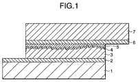
- the proposed cell comprises a photoelectric device serving as a negative electrode, a charge transporting layer, and a counter electrode.
- the photoelectric conversion device is composed of an electrically conductive substrate and a photosensitive layer containing a semiconductor having a dye adsorbed on the surface thereof, a charge transporting layer and a counter electrode.
- the charge transporting layer is made of a redox system serving for charge transport between the negative electrode and the counter electrode, i.e., a positive electrode.
- the photo-electrochemical cell disclosed in the U.S. Patent is a wet type solar cell using an aqueous solution containing an electrolyte salt, such as potassium iodide, (i.e., an electrolytic solution) as a charge transporting layer.
- an electrolyte salt such as potassium iodide
- electrolytic solution i.e., an electrolytic solution
- This system is promising in that the energy conversion efficiency (i.e., the photoelectric conversion efficiency) attained is relatively high for the cost.
- the problem is that the conversion efficiency is not sufficient because of a low open circuit voltage and that, because the charge transporting layer comprises an electrolytic solution containing a low-boiling solvent in a large proportion, such as a potassium iodide aqueous solution, there is a fear that the cell will be short of the electrolytic solution due to evaporation in long-term use only to have a seriously deteriorated photoelectric conversion efficiency or fail to function as a cell.
- a low-boiling solvent such as a potassium iodide aqueous solution
- J. Phys. Chem. B. , vol. 101, p. 2576 (1977) discloses a method for improving photoelectric conversion efficiency of a wet type solar cell, teaching that a treatment with 4-t-butylpyridine, 2-vinylpyridine or poly(2-vinylpyridine) brings about an increase in open circuit voltage. It has turned out, however, that the short circuit current density attained by this method is insufficient for reaching a satisfactory level of conversion efficiency. Besides, the durability of the cell was still insufficient.
- An object of the present invention is to provide a photo-electrochemical cell excellent in photoelectric conversion characteristics such as photoelectric conversion efficiency, particularly open circuit voltage, and durability.
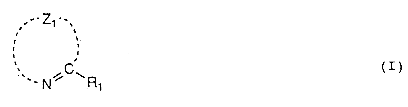
- a photo-electrochemical cell comprising a semiconductor responsive to a radiant ray, a charge transporting layer, and a counter electrode, wherein the cell contains a compound represented by formula (I) having a molecular weight of 1000 or less.
- R 1 represents an alkyl group, a cycloalkyl group, an aralkyl group, an aryl group, a heterocyclic group, an alkoxy group, an aryloxy group or an acylamino group
- Z 1 represents an atomic group necessary to form a 5- or 6-membered aromatic ring together with the nitrogen atom and the carbon atom.
- a photo-electrochemical cell which exhibits excellent photoelectric conversion characteristics and hardly undergoes deterioration in characteristics with time can be obtained.
- the photo-electrochemical cell according to the invention preferably comprises an electrically conductive substrate, a semiconductor layer (photosensitive layer), a charge transporting layer, and a counter electrode.
- the charge transporting layer preferably comprises an ion-transporting electrolyte.
- the photo-electrochemical cell of the invention is characterized by containing the compound represented by formula (I) (hereinafter referred to as compound (I)).
- the compound (I) is preferably basic.
- R 1 represents an alkyl group, a cycloalkyl group, an aralkyl group, an aryl group, a heterocyclic group, an alkoxy group, an aryloxy group or an acylamino group.
- the alkyl group may be either straight or branched and substituted or unsubstituted and preferably contains 1 to 20 carbon atoms.
- alkyl groups examples include methyl, ethyl, propyl, isopropyl, butyl, t-butyl, 3-pentyl, hexyl, heptyl, 2-ethylhexyl, undecyl, dodecyl, chloromethyl, trifluoroethyl, hydroxyethyl, acetoxyethyl, propoxyethyl, isopropyloxyethyl, hydroxypropyl, acetoxypropyl, benzoyloxypropyl, ethoxypropyl, and butoxypropyl groups.
- the cycloalkyl group may be substituted or unsubstituted and may be a condensed ring.
- Preferred cycloalkyl groups are those containing 3 to 20 carbon atoms, such as cyclohexyl and cyclopentyl groups.
- the aralkyl group may be substituted or unsubstituted.
- the aryl moiety may be a condensed ring, and the alkylene moiety may be straight or branched.
- Preferred aralkyl groups are those containing 7 to 27 carbon atoms, such as benzyl, 4-butoxybenzyl and phenethyl groups.
- the aryl group may be substituted or unsubstituted and may be a condensed ring.
- Preferred aryl groups are those containing 6 to 26 carbon atoms, such as phenyl, 2-naphthyl, 4-methoxyphenyl, and 3-chlorophenyl groups.
- the heterocyclic group may be substituted or unsubstituted and may have a condensed ring.
- Preferred heterocyclic groups are those containing 2 to 20 carbon atoms, such as 2-pyridyl, 4-pyridyl, 2-pyrimidyl, 1-methyl-2-imidazolyl, and 3-imidazolyl groups.
- the alkoxy group may be substituted or unsubstituted, and the alkyl moiety thereof may be straight or branched.
- Preferred alkoxy groups are those containing 1 to 20 carbon atoms, such as methoxy, ethoxy, butoxy, isopropyloxy, 2-ethylhexyloxy, and benzyloxy groups.
- the aryloxy group may be substituted or unsubstituted, and the aryl moiety thereof may be a condensed ring.
- Preferred aryloxy groups are those containing 6 to 26 carbon atoms, such as phenoxy, 2-naphthoxy, and 4-methoxyphenoxy groups.
- the acylamino group preferably contains 1 to 20 carbon atoms. Examples of preferred acylamino groups include acetylamino, valerylamino, and benzoylamino groups.
- R 1 preferably represents an alkyl group, an aralkyl group, an aryl group or an alkoxy group. An alkyl group and an aralkyl group are still preferred as R 1 .
- Z 1 represents an atomic group necessary to form a 5- or 6-membered aromatic ring together with the nitrogen and the carbon atoms.
- the aromatic ring is preferably formed by at least one atom selected from the group consisting of carbon, hydrogen, nitrogen, oxygen, and sulfur.
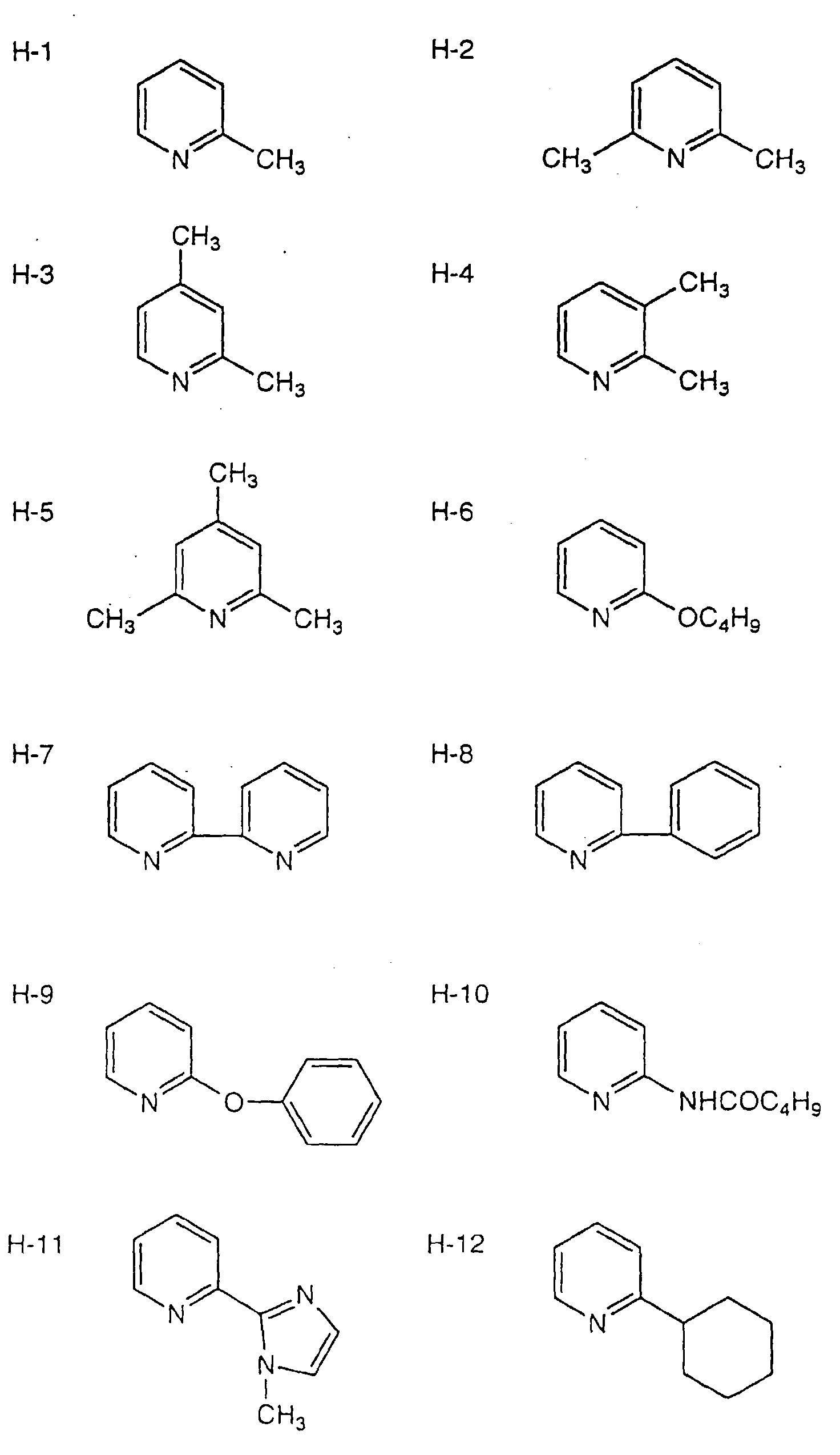
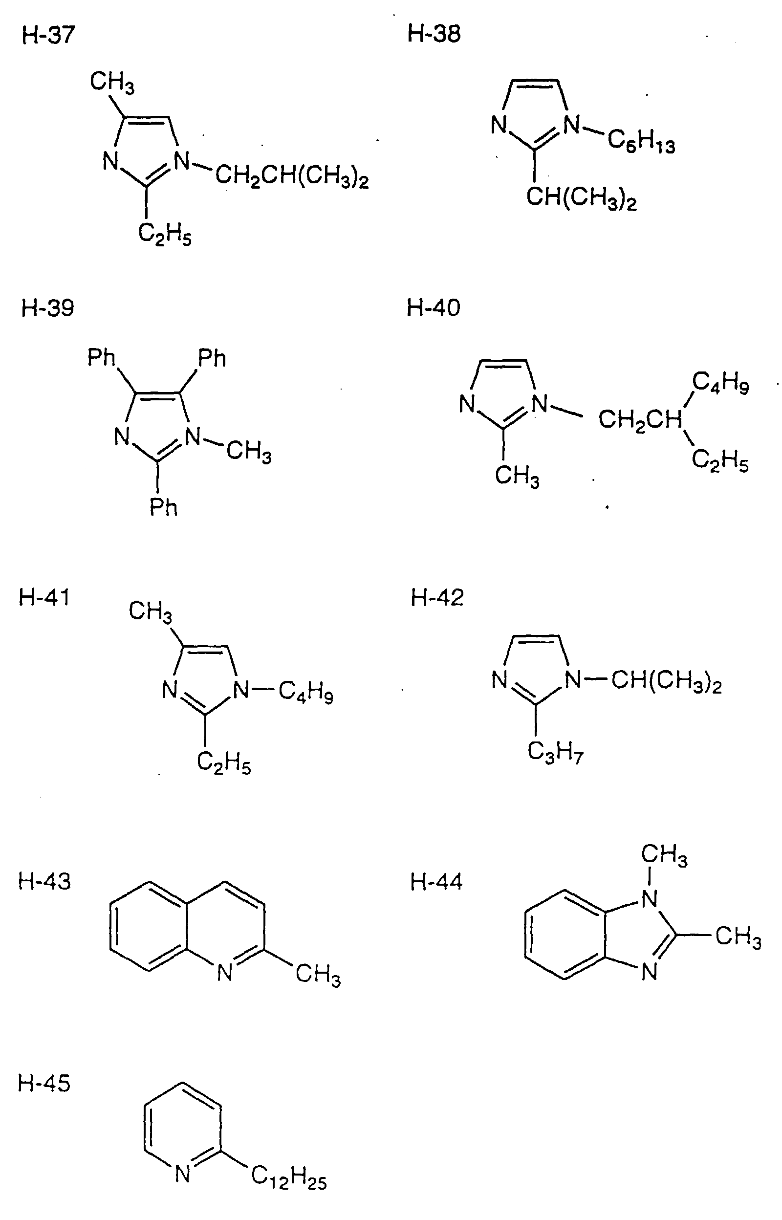
- the aromatic ring made up of Z 1 , nitrogen, and carbon may have a condensed ring. Examples of preferred aromatic rings include pyridine, pyrimidine, pyrazine, pyridazine, quinoline, benzimidazole, triazine, imidazole, oxazole, thiazole, thiadiazole, triazole, and pyrazole rings.
- Pyridine, pyrimidine, pyrazine, quinoline, imidazole, and oxazole rings are still preferred, with pyridine and imidazole rings being particularly preferred.
- a pyridine ring is the most preferred.
- These aromatic rings may have other substituents, such as an alkyl group, in addition to R 1 .
- R 1 on a pyridine ring is preferably an alkyl group or a benzyl group, still preferably a methyl, ethyl, n-propyl, 3-pentyl, isopropyloxyethyl, propyloxyethyl or benzyl group.
- R 1 on an imidazole ring is preferably an alkyl group or an aryl group, still preferably a methyl, ethyl, isopropyl, undecyl or phenyl group.
- the compounds (I) can be used either individually or as a mixture of two or more thereof.
- the compound (I) can be incorporated into the photo-electrochemical cell by addition to an electrolyte or by impregnating a prepared electrode in the compound (I), followed by supplying an electrolyte. Addition direct to an electrolyte is preferred. Whichever manner is followed, the compound (I) comes to be present in the electrolyte, that is, the charge transporting layer to increase the open circuit voltage (i.e., the maximum voltage generated) to improve the conversion efficiency.
- the compound (I) which is basic While it is preferred to use the compound (I) which is basic, it is not favorable that the basic compound (I) has too strong or too weak basicity.
- a preferred basicity, in terms of pKa of the conjugate acid in 25°C water, is 2 to 12, more preferably 3 to 10, particularly preferably 5 to 8. From this standpoint, the compound (I) is preferably a pyridine derivative or an imidazole derivative.
- the compound (I) is preferably added in an amount of 1 to 30%, more preferably 1 to 20%, particularly preferably 5 to 15%, by weight based on the weight of the electrolyte.
- Such well-known additives as 4-t-butylpyridine are not favorable in case where the electrolyte contains iodine, bromine, etc. because they react with iodine, bromine, etc. to reduce the short circuit current density in a photo-electrochemical cell.
- the compound (I) having a substituent on the carbon atom at the ⁇ -position (of the nitrogen atom) is less reactive with iodine, bromine, etc. and therefore less causative of reduction in short circuit current density.
- a compound having an alkenyl group, e.g., a vinyl group, as R 1 is not favorable because the conjugate acid has a high pKa, and the effect on the open circuit voltage is not good enough.
- the compound (I) should have a molecular weight of 1000 or less, preferably 800 or less, still preferably 500 or less. While not limiting, the lower limit of the molecular weight is about 80.
- the molecular weight is so defined that the compound (I) can penetrate easily into the pores of a particulate semiconductor. If the molecular weight exceeds 1000, the compound penetrates into the pores with difficulty, hardly producing the effect of the invention.
- the electrolyte forming the charge transporting layer in the photo-electrochemical cell of the invention comprises an electrolyte component.
- electrolyte components include a metal iodide, such as LiI, NaI, KI, CsI or CaI 2 ; an iodine salt of a quaternary ammonium compound (e.g., an imidazolium compound, a pyridinium compound or a tetraalkylammonium compound); Br 2 and a metal bromide, such as LiBr, NaBr, KBr, CsBr or CaBr 2 ; Br 2 and a bromine salt of a quaternary ammonium compound, such as a tetraalkylammonium bromide or pyridinium bromide; a metal complex, such as a ferrocyananate-ferricyanate or a ferrocene-ferricinium ion; a sulfur compound, such as poly(so
- a metal iodide such as LiI, NaI, KI, CsI or CaI 2
- an iodine salt of a quanternary ammonium compound such as an iodine salt of an imidazolium compound, an iodine salt of a pyridinium compound, and an iodine salt of a tetraalkylammonium compound.
- the electrolyte component is preferably used in a concentration of 0.05 mol/l to 1.5 mol/l, particularly 0.1 mol/l to 0.8 mol/l. Iodine can be added to the electrolyte to previously form a redox pair.
- iodine is preferably added in a concentration of 0.01 to 0.2 mol/l, which will bring about improved effects.
- concentration of the electrolyte component diminishes, the function as an electron carrier tends to be insufficient. Higher concentrations of the electrolyte component than necessary would not bring about further improvement in effect and, moreover, result in reduction of photoelectric current density due to an elevation of viscosity.
- a solvent that can be used in the electrolyte is preferably a compound having excellent ion conductivity.
- To have a low viscosity leads to an improvement in ion mobility.
- To have a high dielectric constant brings about an increase in effective carrier concentration.
- suitable solvents include carbonate compounds, e.g., ethylene carbonate and propylene carbonate; heterocyclic compounds, e.g., 3-methyl-2-oxazolidinone; ether compounds, e.g., dioxane and diethyl ether; chain ethers, e.g., ethylene glycol dialkyl ether, propylene glycol dialkyl ether, polyethylene glycol dialkyl ether, and polypropylene glycol dialkyl ether; alcohols, e.g., methanol, ethanol, ethylene glycol monoalkyl ether, propylene glycol monoalkyl ether, polyethylene glycol monoalkyl ether, and polypropylene glycol monoalkyl ether; polyhydric alcohols, e.g., ethylene glycol, propylene glycol, polyethylene glycol, polypropylene glycol, and glycerol; nitrile compounds, e.g., acetonitrile, glutarod
- carbonate compounds such as ethylene carbonate and propylene carbonate
- heterocyclic compounds such as 3-methyl-2-oxazolidinone
- nitrile compounds such as acetonitrile, glutarodinitrile, methoxyacetonitrile, propionitrile, and benzonitrile
- esters can be used either individually or as a combination of two or more thereof.
- the boiling point of the solvent is preferably 200°C or higher, still preferably 250°C or higher, particularly preferably 270°C or higher, under atmospheric pressure (i.e., 1 atm). Accordingly, S-5 and S-6 are preferred.
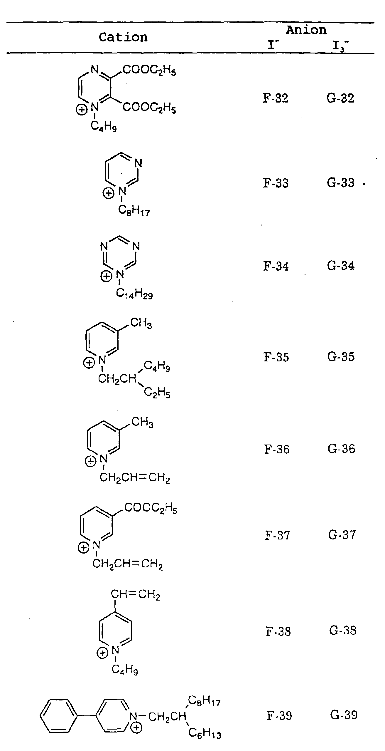
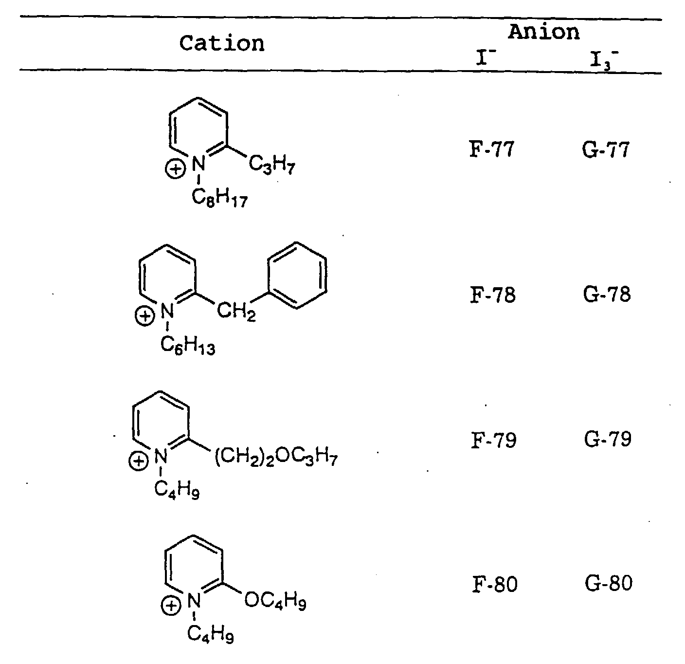
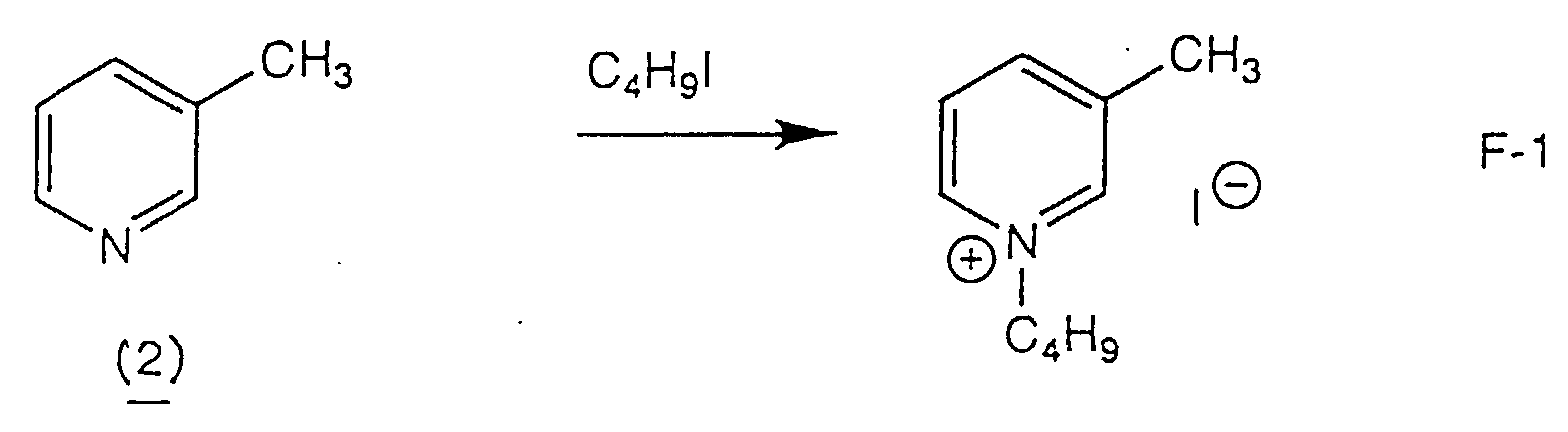
- the photoelectric conversion efficiency and durability that generally 50% by weight or more, desirably 70% by weight or more, more desirably 80% by weight or more, the most desirably 90% by weight or more, of the electrolyte which forms the charge transporting layer is a compound represented by formula (II) (hereinafter simply referred to as the compound (II)): wherein Z 2 represents an atomic group necessary to form a 5- or 6-membered aromatic ring cation together with the nitrogen atom; R 2 represents an alkyl group or an alkenyl group; and a represents 1 or 3.
- formula (II) hereinafter simply referred to as the compound (II): wherein Z 2 represents an atomic group necessary to form a 5- or 6-membered aromatic ring cation together with the nitrogen atom; R 2 represents an alkyl group or an alkenyl group; and a represents 1 or 3.
- the compound (I) is added directly to the electrolyte, it is preferred that 50% by weight or more of the electrolyte exclusive of the compound (I) be the compound (II).
- the compound (II) is preferably a salt that is liquid at 25°C or solid having a low melting point, which is called a molten salt.
- the electrolyte can be comprised solely of such a molten salt, requiring almost no solvent. Having an extremely higher boiling point than general solvents, the compound (II) exhibits low volatility and is effective in preventing deterioration of cell performance by volatilization. Since the compound (II) shows a high short circuit current density as well as improved durability, it provides a photo-electrochemical cell having excellent photoelectric conversion characteristics with high suitability to production.
- the compound (II) preferably has a melting point of 100°C or lower, more preferably 80°C or lower, particularly preferably 60°C or lower.
- the compounds (II) include those which are liquid at 25°C, as stated above.
- the compound (II) preferably has a boiling point (normal boiling point) of 300°C or higher, particularly 400°C or higher.
- the compounds (II) which are solid at 25°C can be incorporated into the electrode of a photo-electrochemical cell in various manners. For example, many of them can be liquefied by addition of the solvent, the compound (II), water or other additives to satisfy the performance requirements as an electrolyte. In some cases, the compound (II) can melt on heating of itself and penetrate into the electrode. Or, the compound (II) can be dissolved in a low-boiling point solvent (e.g., methanol, acetonitrile or methylene chloride) and, after penetration into the electrode, the solvent is removed by heating. Many of the compounds (II) have some hygroscopicity. They can be used as having a water content of about 0.1 to 15% by weight.
- a low-boiling point solvent e.g., methanol, acetonitrile or methylene chloride
- Z 2 represents an atomic group necessary to form a cation of a 5- or 6-membered aromatic ring together with the nitrogen.
- atoms that constitute the aromatic ring preferably include carbon, hydrogen, nitrogen, oxygen, and sulfur.
- the 6-membered aromatic ring completed by Z 2 preferably includes pyridine, pyrimidine, pyridazine, pyrazine, and triazine rings, with a pyridine ring being particularly preferred.
- the 5-membered aromatic ring completed by Z 2 preferably includes oxazole, thiazole, imidazole, pyrazole, isoxazole, thiadiazole, oxadiazole, and triazole rings, with oxazole, thiazole, and imidazole rings being preferred.
- Oxazole and imidazole rings are particularly preferred. These rings can have a substituent(s), such as an alkyl group, an acyloxy group, a heterocyclic group, a cyano group, an alkoxycarbonyl group, a halogen atom, an alkoxy group, an alkenyl group, and an aryl group.
- R 2 represents a substituted or unsubstituted alkyl group or a substituted or unsubstituted alkenyl group.
- the alkyl group may be straight or branched and preferably includes those containing 1 to 24 carbon atoms, e.g., methyl, ethyl, propyl, butyl, isopropyl, pentyl, hexyl, octyl, 2-ethylhexyl, t-octyl, decyl, dodecyl, tetradecyl, 2-hexyldecyl, octadecyl, benzyl, 2-ethoxyethyl, 2-butoxyethyl, heptafluoropropyl, cyanomethyl, methoxycarbonylmethyl, ethoxycarbonylmethyl, imidazoliumhexyl, ethoxycarbonylpropyl, and pyridiniumdo
- the alkenyl group may be straight or branched and preferably includes those having 2 to 24 carbon atoms, such as vinyl and allyl groups.
- R 2 is preferably an alkyl group having 3 to 18 carbon atoms or an alkenyl group having 2 to 18 carbon atoms, still preferably an unsubstituted alkyl group having 4 to 12 carbon atoms, a vinyl group, or an allyl group, particularly preferably an unsubstituted alkyl group having 4 to 12 carbon atoms.
- a represents 1 or 3.
- Ia - represents I - , i.e., a reducing substance in the electrolyte.
- Ia - represents I 3 - , i.e., an oxidizing substance.
- R 2 or other substituents on the 5- or 6-membered aromatic ring completed by Z 2 can have the same quaternary salt of the nitrogen-containing 5- or 6-membered aromatic ring in the formula (II).
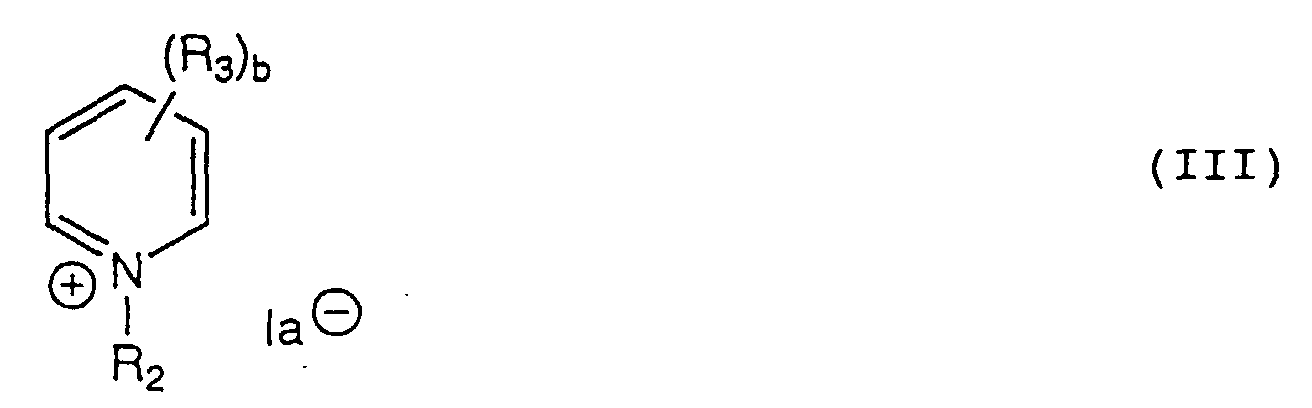
- the compound (II) is preferably a compound represented by formula (III) or (IV) (hereinafter simply referred to as the compound (III) or (IV)): wherein R 2 and a are as defined above; E represents oxygen, sulfur or -NR 5 -; R 3 , R 4 , and R 5 each represent a substituent, preferably a substituted or unsubstituted and straight-chain or branched alkyl group, a substituted or unsubstituted and straight-chain or branched alkenyl group, a substituted or unsubstituted aryl group which may have a condensed ring, a substituted or unsubstituted heterocyclic group which may have a condensed ring, an alkoxy group, an acyloxy group, an alkoxycarbonyl group, a cyano group, or a halogen atom; b represents an integer of 0 to 5; and c represents an integer of 0 to 3.
- the alkyl group preferably has 1 to 24 carbon atoms and includes methyl, ethyl, isopropyl, butyl, t-butyl, octyl, 2-methoxyethyl, benzyl, trifluoromethyl, cyanomethyl, ethoxycarbonylmethyl, 6-(3-octylimidazolium-1-yl)hexyl, 3-(1-octylpyridinium-4-yl)propyl, and 3-(1-butyl-3-methylpyridinium-4-yl)propyl groups.
- the alkenyl group preferably has 2 to 24 carbon atoms and includes vinyl and allyl groups.
- the aryl group preferably has 6 to 24 carbon atoms and includes phenyl, 4-methylphenyl, 3-cyanophenyl, 2-chlorophenyl, and 2-naphthyl groups.
- the heterocyclic group preferably contains 2 to 24 carbon atoms. Where it is a nitrogen-containing heterocyclic group, the nitrogen atom in the ring may be quaternized.
- the heterocyclic group includes 4-pyridyl, 2-pyridyl, 1-octylpyridinium-4-yl, 2-pyrimidyl, 2-imidazolyl, and 2-thiazolyl groups.
- the alkoxy group preferably has 1 to 24 carbon atoms and includes methoxy, ethoxy, butoxy, and octyloxy groups.
- the acyloxy group preferably has 1 to 24 carbon atoms and includes acetyloxy and benzoyloxy groups.
- the alkoxycarbonyl group preferably has 2 to 24 carbon atoms and includes methoxycarbonyl and ethoxycarbonyl groups.
- the halogen atom includes chlorine and bromine.
- R 3 , R 4 , and R 5 each more preferably represents an alkyl group, an alkenyl group, an alkoxy group, an alkoxycarbonyl group, a cyano group or a halogen atom.
- R 3 still preferably represents an alkyl group, an alkenyl group, an alkoxycarbonyl group or a cyano group, and particularly preferably a methyl group, an ethyl group, a cyanomethyl group, an alkoxycarbonylmethyl group, a vinyl group or an alkoxycarbonyl group.
- a methyl group is the most preferred as R 3 .
- R 4 still preferably represents an unsubstituted alkyl group having 1 to 12 carbon atoms or an alkenyl group having 2 to 12 carbon atoms.
- a methyl group is particularly preferred as R 4 .
- R 5 still preferably represents an alkyl group or an alkenyl group, particularly preferably an unsubstituted alkyl group having 1 to 12 carbon atoms, a vinyl group or an allyl group.
- b is an integer 0 to 5, preferably an integer 0 to 2, particularly 0 or 1.
- E preferably represents oxygen or -NR 5 -, and c is an integer 0 to 3, preferably 0 to 2.
- c is preferably 1 or 2.
- E is -NR 5 -, c is preferably 0.
- R 2 and R 3 in formula (III) may have the same pyridinium salt as in formula (III).
- R 2 , R 4 and R 5 in formula (IV) may have the same oxazolium salt, thiazolium salt or imidazolium salt as in formula (IV).
- the compounds (II) can be used either individually or as a mixture thereof. It is preferred to use a mixture of compounds (II) having the same cation and different anions at an arbitrary I 3 - to I - ratio.
- the ratio of I 3 - to I - is preferably 0.1 to 50 mol%, more preferably 0.1 to 20 mol%, further more preferably 0.5 to 10 mol%, particularly 0.5 to 5 mol%.
- the compounds (II) those having I - are generally synthesized with ease by reacting an alkyl iodide, an alkenyl iodide, etc., with a nitrogen-containing 5- or 6-membered aromatic ring compound, such as pyridine, under heating.
- Those having I 3 - are easily synthesized by adding I 2 to the compound (II) having I - . Accordingly, the above-described mixture is conveniently prepared by previously synthesizing a compound having I - and, on use as an electrolyte, adding a predetermined amount of I 2 .
- the charge transporting layer has a thickness of preferably 0.001 to 200 ⁇ m, still preferably 0.1 to 100 ⁇ m.
- the electrolyte may be penetrated into the semiconductor layer.
- the semiconductor used in the invention serves as a photoreceptor that absorbs light to generate electrons and positive holes.
- the semiconductor which can be used in the invention includes simple substance semiconductors, e.g., Si or Ge, compound semiconductors, such as metal chalcogenides (e.g., oxides, sulfides, and selenides), and perovskite semiconductors.
- the metal chalcogenides include an oxide of titanium, tin, zinc, iron, tungsten, zirconium, hafnium, strontium, indium, cerium, yttrium, lanthanum, vanadium, niobium or tantalum; a sulfide of cadmium, zinc, lead, silver, antimony or bismuth; a selenide of cadmium or lead; and cadmium telluride.
- Other compound semiconductors include a phosphide of zinc, potassium, indium or cadmium, gallium arsenide, copper indium selenide, and copper indium sulfide.
- the perovskite semiconductors include strontium titanate, calcium titanate, sodium titanate, barium titanate, and potassium niobate.
- Preferred semiconductors for use in the invention include Si, TiO 2 , SnO 2 , Fe 2 O 3 , WO 3 , ZnO, Nb 2 O 5 , CdS, ZnS, Pbs, Bi 2 S 3 , CdSe, GaP, InP, GaAs, CdTe, CuInS 2 , and CuInSe 2 . Still preferred are TiO 2 , ZnO, SnO 2 , Fe 2 O 3 , WO 3 , Nb 2 O 5 , CdS, PbS, CdSe, InP, GaAs, CuInS 2 , and CuInSe 2 .
- the semiconductor may be a single crystal or polycrystalline.
- a single crystal is preferred for conversion efficiency, while a polycrystalline semiconductor is preferred from the standpoint of production cost, supply of raw materials, and an energy payback time.
- Finely particulate semiconductors having a particle size on the order of nanometers to microns are particularly preferred.
- the particulate semiconductors preferably have an average primary particle size of 5 to 200 nm, particularly 8 to 100 nm, in terms of a projected circle-equivalent diameter.
- the semiconductor particles in a dispersed state preferably have an average particle size of 0.01 to 100 ⁇ m.
- the particulate semiconductors particularly metal oxide semiconductors
- dyes For example, TiO 2 , ZnO, SnO 2 , Fe 2 O 3 , WO 3 , and Nb 2 O 5 are preferred for semiconductors to be dye-sensitized.
- TiO 2 is particularly preferred to be dye-sensitized.
- the photo-electrochemical cells using dye-sensitized semiconductor particles will be illustrated in more detail.
- the photo-electrochemical cell using dye-sensitized semiconductor particles (sometimes, called a dye-sensitized photoelectric conversion device) is preferably composed of an electrically conductive substrate, a photosensitive layer provided on the conductive substrate (i.e., a layer of semiconductor particles having adsorbed thereon a dye), a charge transporting layer, and a counter electrode.
- the electrically conductive substrate includes a substrate made of a conductive material, such as metal, and a nonconductive substrate made of glass or plastics having on the surface thereof an electrical conductor layer.
- Preferred conductors for use in the latter type of conductive substrates include metals (e.g., platinum, gold, silver, copper, aluminum, rhodium, and indium), carbon, and electrically conducting metal oxides (e.g., indium tin oxide and F-doped tin oxide).
- metals e.g., platinum, gold, silver, copper, aluminum, rhodium, and indium
- carbon e.g., aluminum rhodium, and indium
- electrically conducting metal oxides e.g., indium tin oxide and F-doped tin oxide
- a conductive glass substrate obtained by depositing F-doped tin dioxide on a transparent substrate made of inexpensive soda-lime float glass.
- the conductor layer preferably has a thickness of about 0.
- the conductive substrate preferably has as low a surface resistivity as possible.
- a desirable surface resistivity is 100 ⁇ /cm 2 or smaller, particularly 40 ⁇ /cm 2 or smaller. While not limiting, the practically possible minimal surface resistivity is about 0.1 ⁇ /cm 2 .
- the conductive substrate be substantially transparent to light.
- substantially transparent means that the light transmission is at least 10%, preferably 50% or more, still preferably 70% or more.
- a glass or plastic substrate having an electrically conductive metal oxide layer is preferred as a transparent substrate.
- the amount of the conductive metal oxide is preferably 0.01 to 100 g/m 2 .
- the transparent conductive substrate is preferably used in such a manner that incident light enters from the side of the glass or plastic substrate.
- the semiconductor particles are applied to the conductive substrate by, for example, a method comprising coating the conductive substrate with a dispersion or colloidal solution of the semiconductor particles or a sol-gel process comprising applying a precursor of the semiconductor particles onto the conductive substrate and hydrolyzing the precursor with moisture in air to form a particulate semiconductor film.
- a dispersion of the semiconductor particles is prepared by the above-mentioned sol-gel process, a method comprising grinding a semiconductor in a mortar, or a method comprising wet grinding a semiconductor in a mill.
- a synthetic semiconductor as precipitated in a solvent in the form of fine particles can also be used as such.
- Useful dispersing media include water and various organic solvents, such as methanol, ethanol, isopropyl alcohol, dichloromethane, acetone, acetonitrile, and ethyl acetate.
- organic solvents such as methanol, ethanol, isopropyl alcohol, dichloromethane, acetone, acetonitrile, and ethyl acetate.
- a polymer, a surface active agent, an acid, a chelating agent, and the like may be added as a dispersant if desired.
- the semiconductor particles it is preferable for the semiconductor particles to have a large surface area so that they may adsorb as large an amount of a dye as possible.
- the surface area of the semiconductor particles in the state applied to the conductive substrate is preferably 10 times or more, still preferably 100 times or more, the projected area.
- the upper limit of the surface area is, while not limited, practically about 1000 times the projected area.
- the thickness of the particulate semiconductor layer increases, the amount of the supported dye per unit projected area increases to show increased ability of capturing light, but the distance of diffusion of generated electrons also increases, which results in an increased loss due to re-coupling of charges. Accordingly, there is a favorable thickness range for the particulate semiconductor layer, which is typically from 0.1 to 100 ⁇ m.
- the thickness is preferably 1 to 30 ⁇ m, still preferably 3 to 20 ⁇ m. It is preferred that the semiconductor particles applied to the substrate be calcined so that the particles may be brought into electronic contact among themselves to secure improved film strength and improved adhesion to the substrate.
- a preferred calcined temperature is 40°C or higher and lower than 700°C, particularly from 40 to 650°C.
- the calcined time is usually from 10 minutes to about 10 hours.
- the calcined particulate semiconductor layer can be subjected to chemical plating with a titanium tetrachloride aqueous solution or electrochemical plating with a titanium trichloride aqueous solution.
- the amount of the semiconductor particles to be applied is preferably 0.5 to 500 g/m 2 , still preferably 5 to 100 g/m 2 .
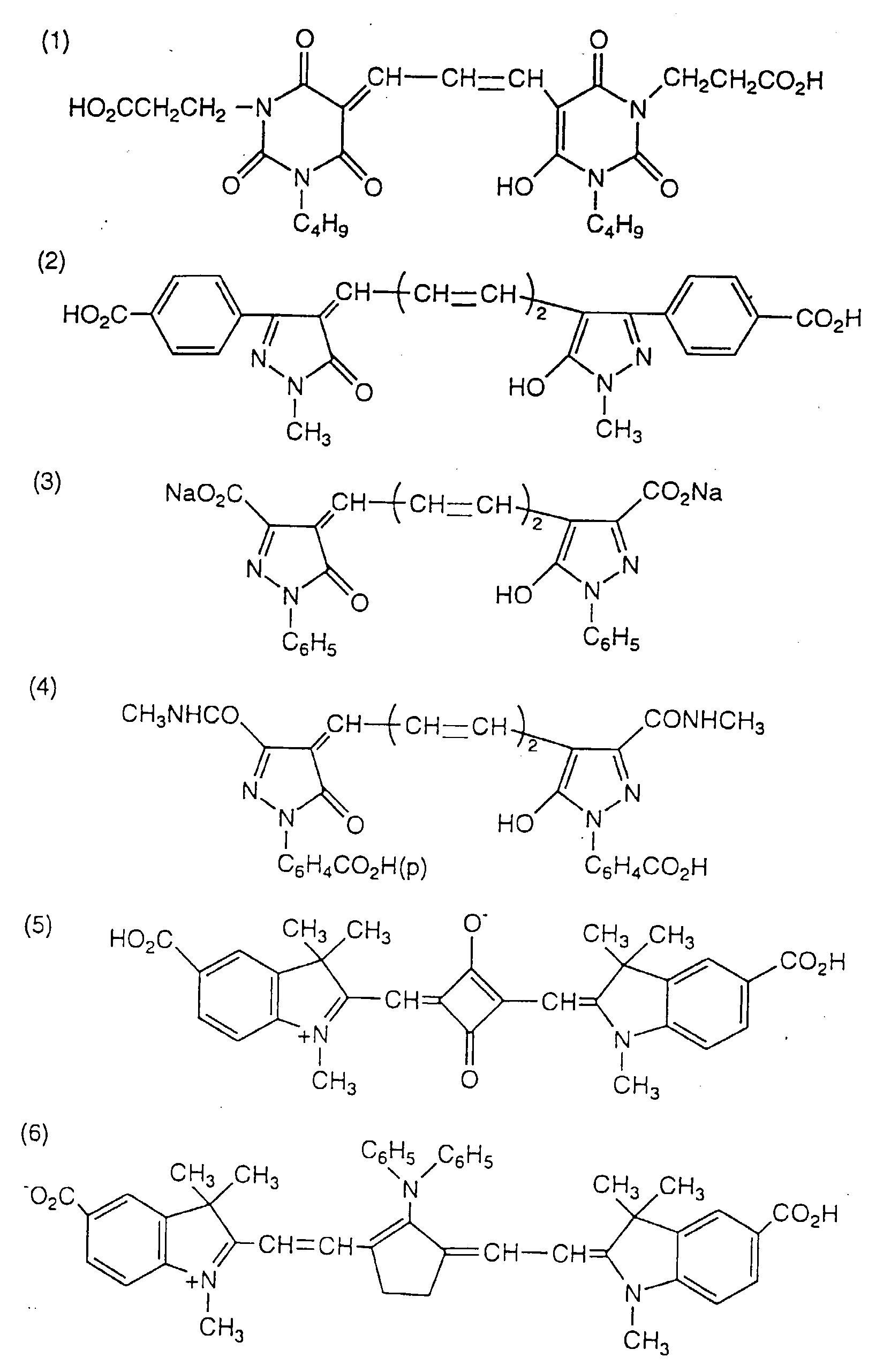
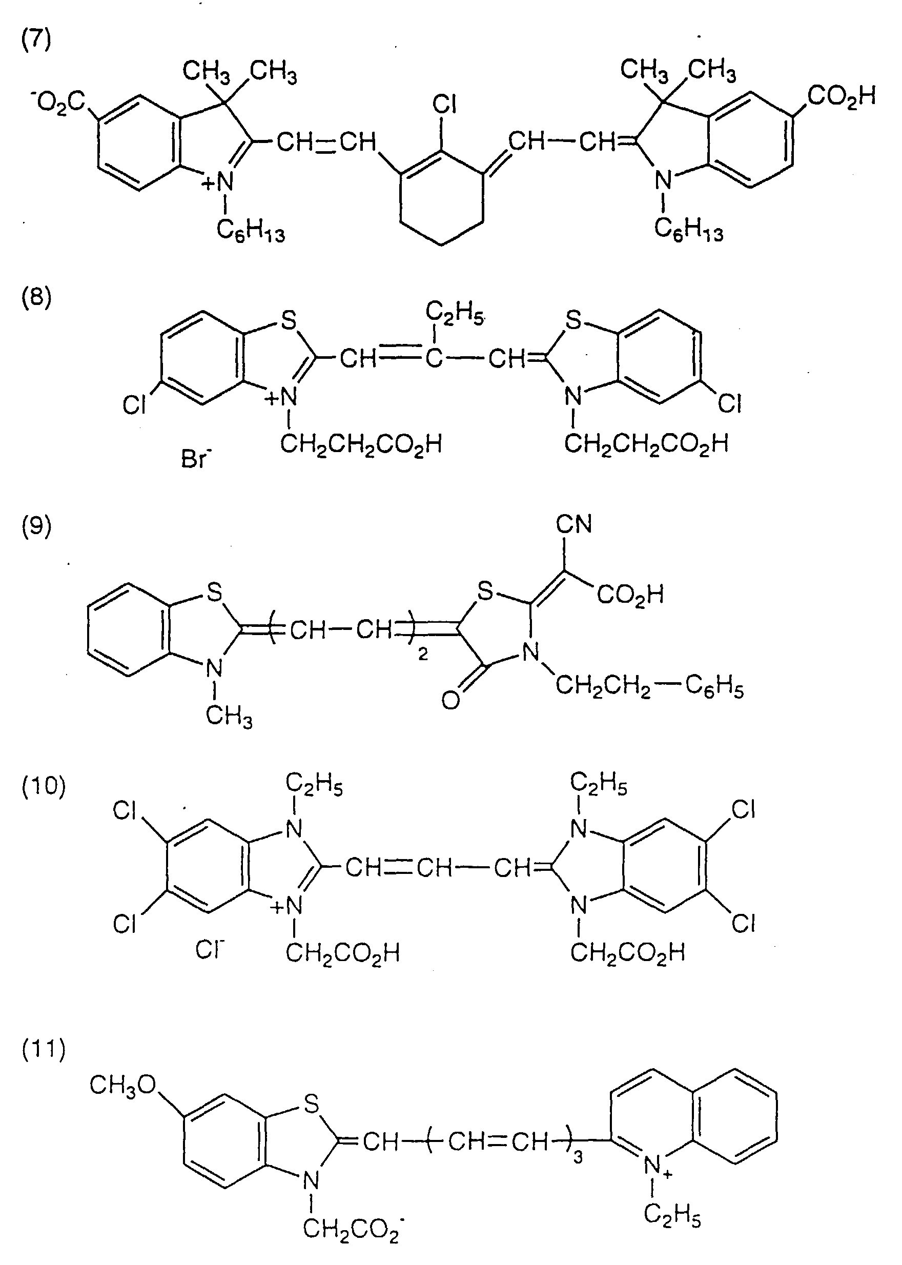
- the dye which can be used in the present invention preferably includes complex dyes (particularly metal complex dyes) and/or polymethine dyes. It is preferred for the dye to have an appropriate interlocking group for linking to the surface of the semiconductor particles.
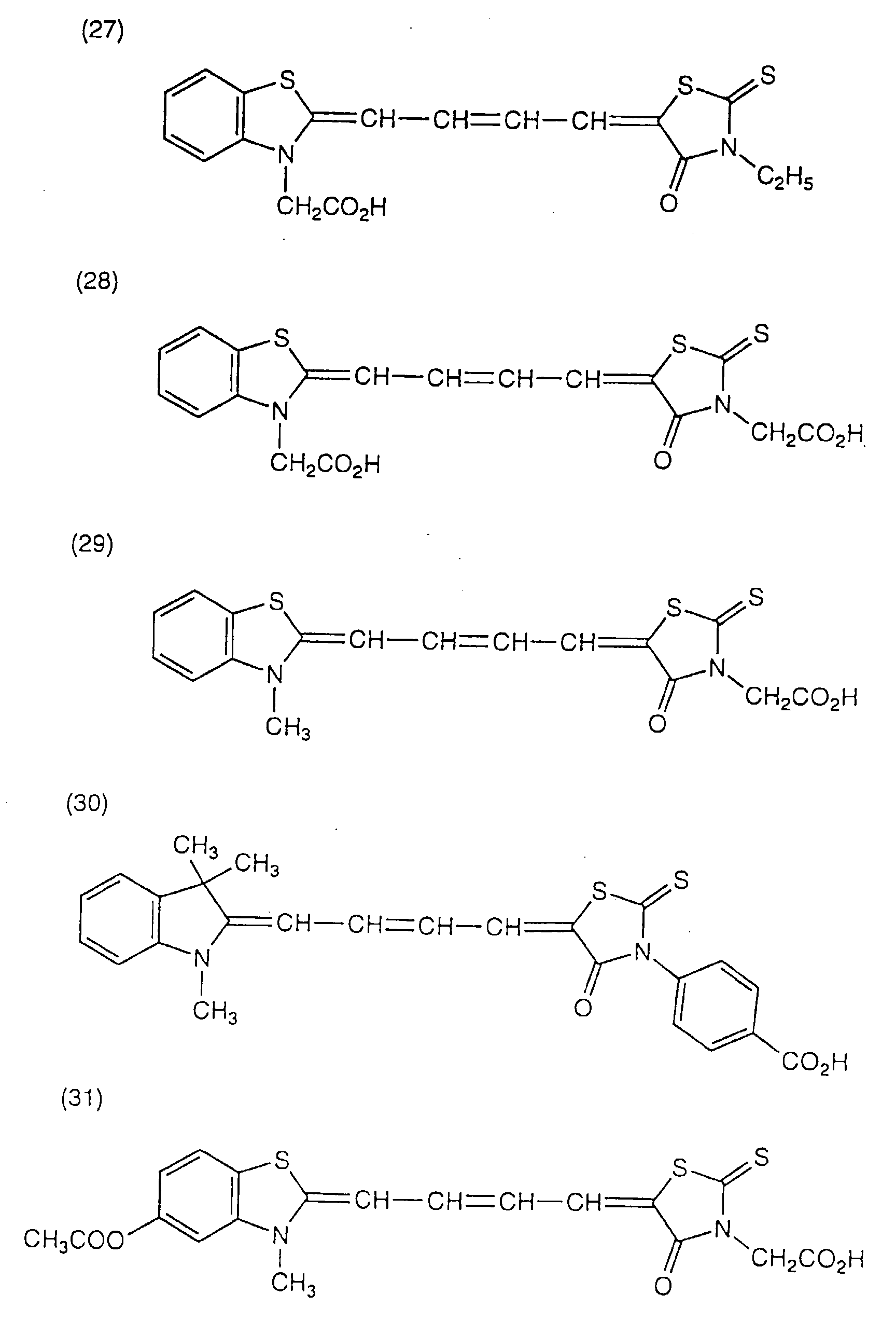
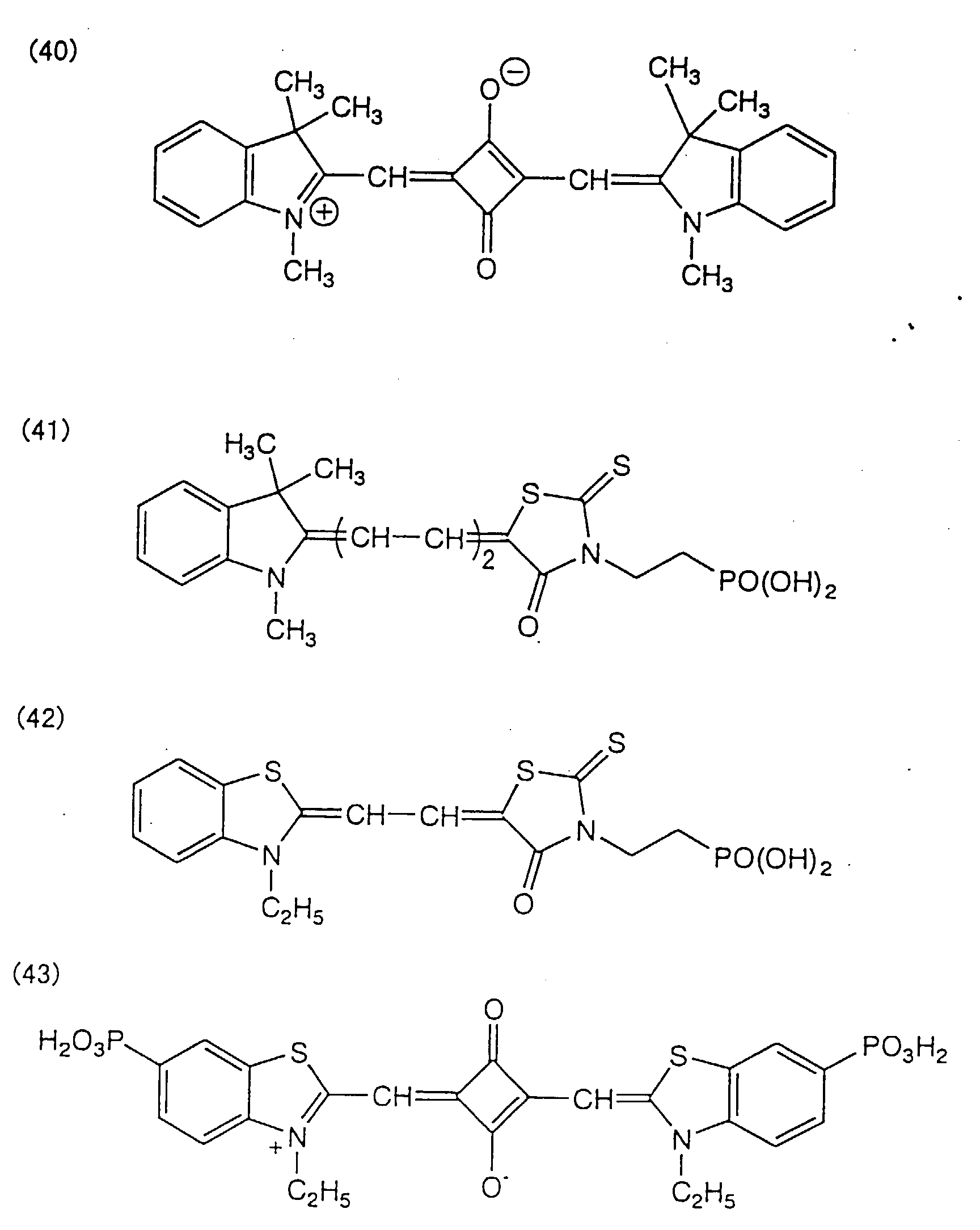
- Preferred interlocking groups include -COOH, -SO 3 H, a cyano group, -P(O)(OH) 2 , -OP(O)(OH) 2 , and chelating groups having pi conductivity, such as oxime, dioxime, hydroxyquinoline, salicylate and ⁇ -keto-enolate groups. Particularly preferred of them are -COOH, -P(O)(OH) 2 , and -OP(O)(OH) 2 .
- the interlocking group may be in the form of a salt with an alkali metal, etc. or an intramolecular salt.
- the methine chain of a polymethine dye has an acidic group as in the case where the methine chain forms a squarylium ring or a croconium ring, that moiety can be used as a interlocking group.
- the metal complex dyes preferably include ruthenium complex dyes. Those represented by formula (V) are still preferred.
- (Y 1 ) p RuB a B b B c wherein Y 1 represents a ligand selected from the group consisting of Cl, SCN, H 2 O, Br, I, CN, -NCO and SeCN; p represents an integer of 0 to 2, preferably 2; and B a , B b , and B c each represent an organic ligand selected from B-1 to B-8 shown below.
- R a represents a hydrogen atom, a halogen atom, a substituted or unsubstituted alkyl group having 1 to 12 carbon atoms, a substituted or unsubstituted aralkyl group having 7 to 12 carbon atoms or a substituted or unsubstituted aryl group having 6 to 12 carbon atoms.
- the alkyl group and the alkyl moiety of the aralkyl group may be either straight or branched, and the aryl group and the aryl moiety of the aralkyl group may be either monocyclic or polycyclic (condensed rings or independent rings).
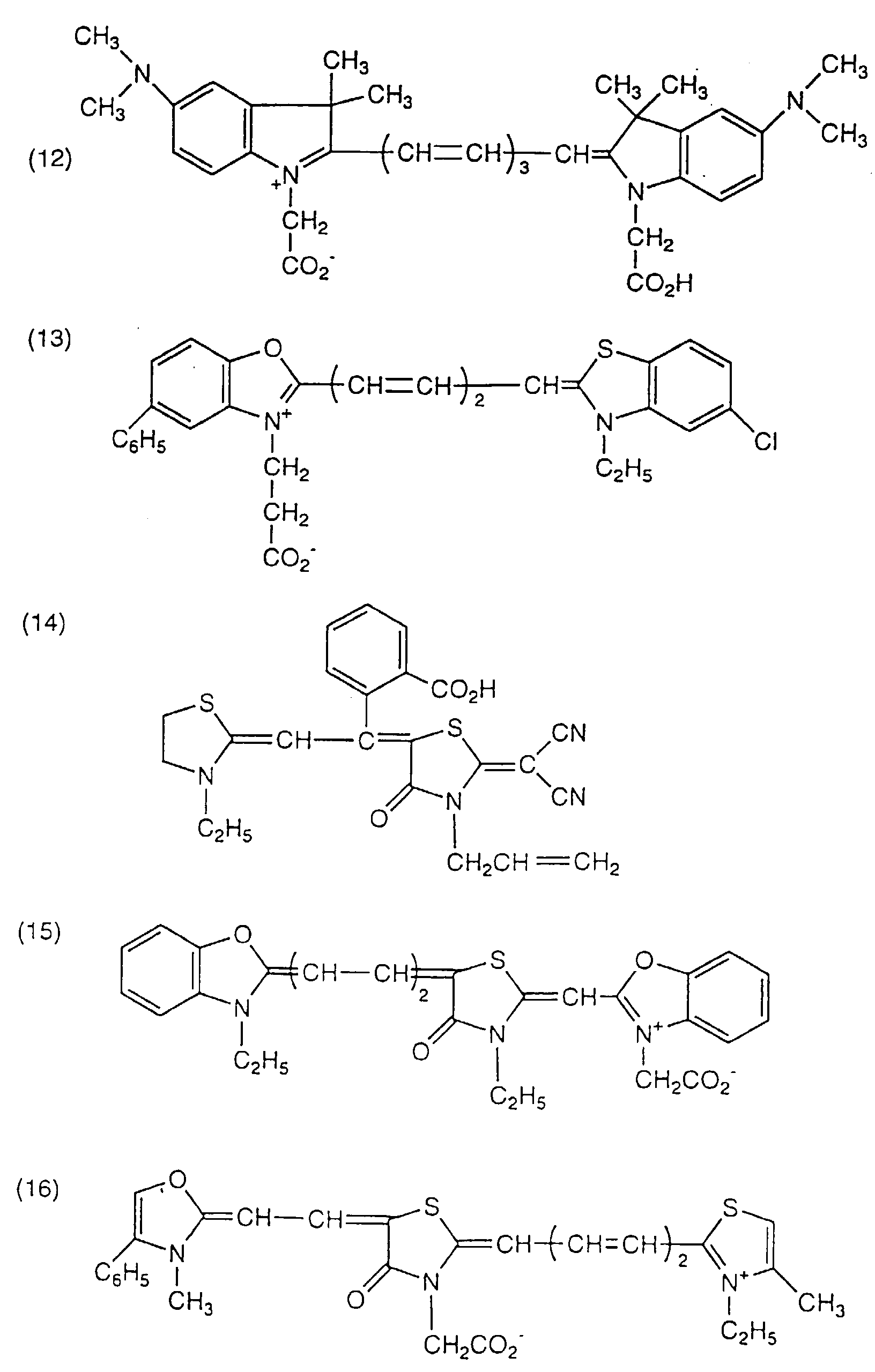
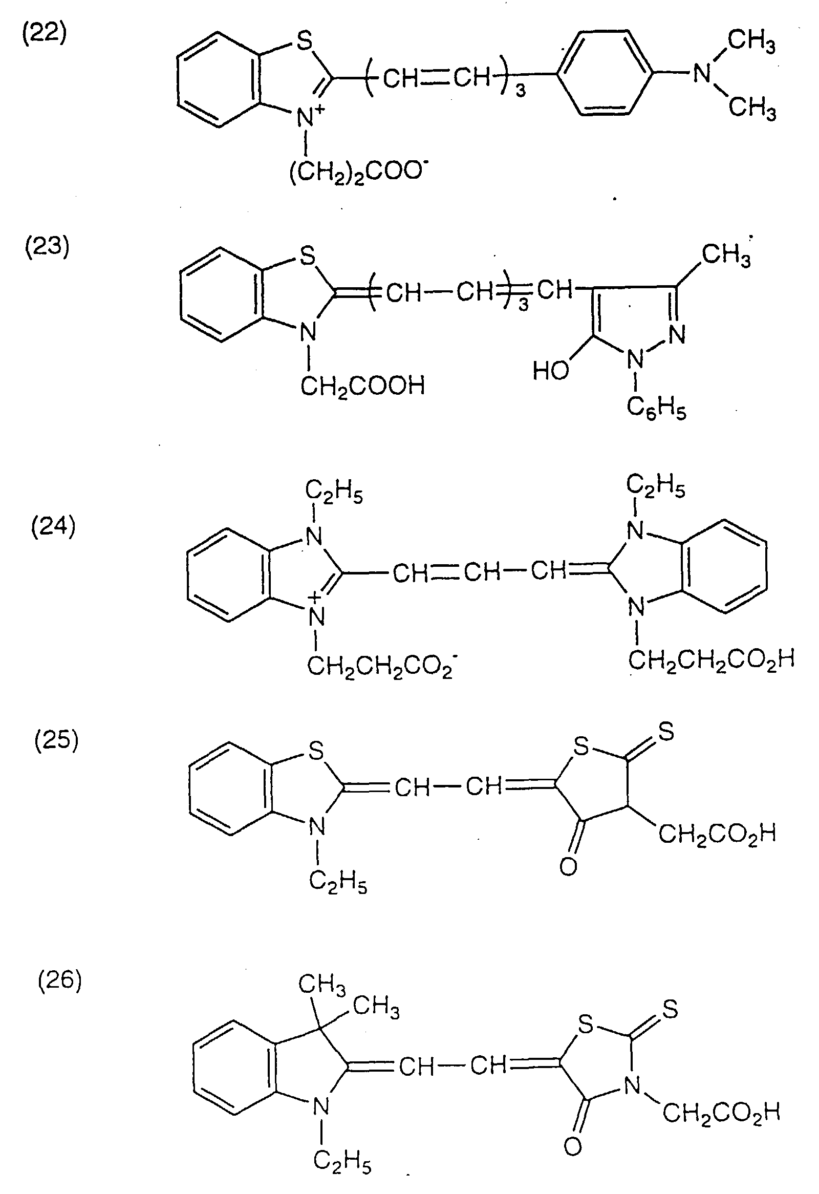
- the polymethine dyes preferably include those represented by formulae (VI) and (VII) shown below.
- R b and R f each represent a hydrogen atom, an alkyl group, an aryl group or a heterocyclic group
- R c , R d , and R e each represent a hydrogen atom or a substituent
- R b , R c , R d , R e , and R f may appropriately be taken together to form a ring
- X 11 and X 12 each represent a nitrogen atom, an oxygen atom, a sulfur atom, a selenium atom or a tellurium atom
- n11 and n13 each represent an integer of 0 to 2
- n12 represents an integer of 1 to 6.
- the compound of formula (VI) may have a counter ion in agreement with the charge quantity of the whole molecule.
- the alkyl, aryl, and heterocyclic groups may have a substituent; the alkyl group may be straight or branched; the aryl and heterocyclic groups may be monocyclic or polycyclic (condensed rings); and the ring formed of R b , R c , R d , R e , and R f may have a substituent and may be monocyclic or polycyclic.
- Z a represents a non-metal atomic group necessary to form a nitrogen-containing heterocyclic group
- R g represents an alkyl group or an aryl group
- Q represents a mono- or polymethine group necessary to complete a (poly)methine dye
- X 13 represents a counter ion in balance
- n14 represents a number of from 0 up to 10 that is necessary to neutralize the charge of the molecule.
- the nitrogen-containing heterocyclic ring formed by Za may have a substitutent and may be a single ring or a condensed ring; the alkyl or aryl groups may have a substituent; the alkyl group may be straight or branched; and the aryl group may be monocyclic or polycyclic (condensed rings).
- the dyes represented by formula (VII) preferably include those represented by formulae (VIII-a) through (VIII-d): wherein R 11 , R 12 , R 13 , R 14 , R 15 , R 21 , R 22 , R 23 , R 24 , R 31 , R 32 , R 33 , R 41 , R 42 , and R 43 each represent a hydrogen atom, an alkyl group, an aryl group or a heterocyclic group; Y 11 , Y 12 , Y 21 , Y 22 , Y 31 , Y 32 , Y 33 , Y 34 , Y 35 , Y 41 , Y 42 , Y 43 , Y 44 , Y 45 , and Y 46 each represent an oxygen atom, a sulfur atom, a selenium atom, a tellurium atom, -CR 16 R 17 - or -NR 18 -; R 16 , R 17 , and R 18 each represent a
- the compounds represented by formulae (VIII-a) through (VIII-d) may have a counter ion in agreement with the charge quantity of the whole molecule.
- the alkyl, aryl, and heterocyclic groups may have a substituent; the alkyl group may be straight or branched; and the aryl or heterocyclic group may be monocyclic or polycyclic (condensed rings).
- the compounds of formulae (VI) and (VII) can be synthesized in accordance with the methods described, e.g., in F.M. Harmer, Heterocyclic Compounds-Cyanine Dyes and Related Compounds , John Wiley & Sons, New York & London (1964); D.M. Sturmer, Heterocyclic Compounds-Special topics in heterocyclic chemistry , Ch. 18, ⁇ 14, Items 482-515, John Wiley & Sons, New York & London (1977); Rodd's Chemistry of Carbon Compounds , 2nd Ed., vol. IV, part B, Ch. 15, Items 369-422, Elsevier Science Publishing Co., Inc., New York (1977); and British Patent 1,077,611.
- Adsorption of the dye onto semiconductor particles is usually effected by immersing well-dried semiconductor particles in a dye solution for several hours at room temperature or, as taught in JP-A-7-249790, while refluxing.
- Dye adsorption may be carried out either before or after applying the semiconductor particles to the substrate or simultaneously with application of the semiconductor particles.
- the unadsorbed dye is preferably removed by washing.
- dye adsorption is preferably conducted after the calcining. It is particularly preferred that the dye be adsorbed quickly before water is adsorbed to the surface of the calcined semiconductor layer.
- the dyes may be used either individually or as a combination of two or more thereof.
- the dyes to be combined can be selected so as to maximize the breadth of the wavelength region for photoelectric conversion.
- the dye or dyes are preferably used in an amount of 0.01 to 100 mmol per m 2 of the substrate and 0.01 to 1 mmol per gram of the semiconductor particles. With too small an amount of the dye, the sensitizing effect would be insufficient. If the dye is used in too large an amount, the non-adsorbed dye will float to reduce the sensitizing effect.
- a colorless compound may be adsorbed together with the dye so as to lessen the interaction among dye molecules, such as association.
- Hydrophobic compounds such as carboxyl-containing steroid compounds (e.g., cholic acid) can be used for this purpose.
- the counter electrode in the photo-electrochemical cell functions as a positive electrode.
- the counter electrode usually has a conductive substrate, such as those described above, but a substrate is not always required as far as sufficient strength is secured. For achieving air tightness, use of a substrate is advantageous, though.
- At least one of the conductive substrate of the semiconductor electrode and the counter electrode must be substantially transparent so that incident light can reach the photosensitive layer. It is preferred for the photo-electrochemical cell of the invention that the conductive substrate of the semiconductor electrode be transparent and that light be incident upon this side. In this case, it is still preferred that the counter electrode have light reflecting properties.
- the counter electrode that can be used in the photo-electrochemical cell includes glass or plastic having metal or a conductive oxide deposited thereon. Metal can be deposited by vacuum evaporation, sputtering or a like technique for thin film formation to obtain a deposit thickness of 5 ⁇ m or smaller, preferably 5 nm to 3 ⁇ m.
- a preferred counter electrode is a glass plate having platinum deposited thereon by vacuum evaporation or a metal thin film formed by vacuum evaporation or sputtering.
- the photosensitive layer may have a single layer structure or a multilayer structure as designed according to the end use.
- a single photosensitive layer may have a dye of a kind or a mixture of two or more kinds of dyes.
- the photo-electrochemical cell of the invention may have its sides sealed with a polymer, an adhesive, etc. to prevent oxidative deterioration.
- Synthesis Example 1 presents a process for synthesizing Compound H-21.
- Electrically conductive glass having an F-doped tin oxide coat (TCO Glass-U, produced by Asahi Glass Co., Ltd.; surface resistivity: about 30 ⁇ /cm 2 ) was cut to squares with 20 mm-sides.
- the titanium dioxide dispersion prepared in item 1) was applied with a glass bar to the conductive side of 8 glass pieces at a time in the following manner.
- An adhesive tape was stuck to one end (over a 3 mm width from the edge) of the conductive surface of each glass piece, and 8 glass pieces were aligned in two lines without gap to make a 4 cm wide and 8 cm long strip with their adhesive tape-stuck edges making both sides (8 cm long) of the strip as spacers.
- the coating weight of the titanium dioxide particles was adjusted to 20 g/m 2 . After coating, the adhesive tape was removed. The coating layer was air-dried at room temperature for 1 day and then calcined in an electric muffle furnace (Model FP-32, manufactured by Yamato Kagaku) at 450°C for 30 minutes. After being cooled out of the furnace, the coated glass substrate was immersed in a 3 ⁇ 10 -4 mol/l ethanol solution of the dye shown in Table 2 below for 3 hours. The amount of the dye coated was selected appropriately from 0.1 to 10 mmol/m 2 according to the dye.
- the dyed glass substrate was then immersed in 4-t-butylpyridine, the compound (I) shown in Table 2, or 2-vinylpyridine as a base for 15 minutes and dried spontaneously.
- the amount of the base introduced was 5 to 10 wt% based on the electrolyte introduced later. Comparative cells containing no base were prepared without this immersion step.
- the thickness of the thus obtained photosensitive layer was 10 ⁇ m.
- An electrolyte was prepared by dissolving the salt shown in Table 2 and iodine in the organic solvent shown in Table 2 in concentrations of 0.7 mol/l and 0.035 mol/l, respectively.
- the dye-sensitized TiO 2 electrode prepared above and a Pt-deposited glass substrate (counter electrode) were brought into contact with the TiO 2 electrode layer 3 and the Pt deposit layer 6 facing each other.
- the electrolyte was introduced by penetration into the TiO 2 electrode sandwiched in between the glass substrates by use of osmotic pressure to form an electrolyte layer.
- photo-electrochemical cells 101 to 131 composed of a conductive glass substrate (glass 1 having a conductor layer 2), a TiO 2 electrode 3, a dye layer 4, an electrolyte layer 5, a Pt layer 6, and glass 7 in this order.
- Photo-electrochemical cells 201 to 232 were prepared in the same manner as in Example 1, except that the immersion treatment of the TiO 2 electrode with a base was not conducted and that the electrolyte was prepared by mixing the compound (II) (salt) shown in Table 3 below and the solvent shown in Table 3 (the weight ratio of the salt to the total amount of the salt and the solvent is shown in parentheses in Table 3) and adding thereto 20 mol%, based on the compound (II), of the compound (I) (base) or a comparative base and 2 mol%, based on the compound (II), of iodine.
- the electrolyte was prepared by mixing the compound (II) (salt) shown in Table 3 below and the solvent shown in Table 3 (the weight ratio of the salt to the total amount of the salt and the solvent is shown in parentheses in Table 3) and adding thereto 20 mol%, based on the compound (II), of the compound (I) (base) or a comparative base and 2 mol%
- the photoelectric characteristics of the photo-electrochemical cells prepared in Examples 1 and 2 were evaluated as follows.
- the conductive glass 1 and the Pt-deposited glass 7 were connected by means of alligator clips, and the cell was irradiated with pseudo-sunlight containing no ultraviolet rays having an intensity of 86 mW/cm 2 which was obtained by cutting light from a 500 W xenon lamp (produced by Ushio Inc.) through AM1.5 Filter (produced by Oriel) and a sharp cut filter (Kenko L-42).
- Tables 3 and 5 prove that the photo-electrochemical cells in which the electrolyte comprises 50 wt% or more of the compound (II) and contains the compound (I) exhibit excellent improvements in short circuit current density, conversion efficiency and durability as compared with those containing no compound (I). It is also seen that the conversion efficiency and the durability are further improved with an increase of the weight ratio of the compound (II).
- the effects produced by poly(2-vinylpyridine), which is a conventional additive, are not good enough.
Landscapes
- Engineering & Computer Science (AREA)
- Power Engineering (AREA)
- Microelectronics & Electronic Packaging (AREA)
- Chemical & Material Sciences (AREA)
- Chemical Kinetics & Catalysis (AREA)
- Electrochemistry (AREA)
- Hybrid Cells (AREA)
- Photovoltaic Devices (AREA)
Abstract
Description


| (Y1)pRuBaBbBc | ||||||
| No. | Y1 | p | Ba | Bb | Bc | Ra |
| R-1 | SCN | 2 | B-1 | B-1 | - | - |
| R-2 | CN | 2 | B-1 | B-1 | - | - |
| R-3 | Cl | 2 | B-1 | B-1 | - | - |
| R-4 | Br | 2 | B-1 | B-1 | - | - |
| R-5 | I | 2 | B-1 | B-1 | - | - |
| R-6 | SCN | 2 | B-1 | B-2 | - | H |
| R-7 | SCN | 1 | B-1 | B-3 | - | - |
| R-8 | Cl | 1 | B-1 | B-4 | - | H |
| R-9 | I | 2 | B-1 | B-5 | - | H |
| R-10 | SCN | 2 | B-1 | B-6 | - | H |
| R-11 | CN | 2 | B-1 | B-7 | - | H |
| R-12 | Cl | 1 | B-1 | B-8 | - | H |
| R-13 | - | 0 | B-1 | B-1 | B-1 | - |


| Sample No. | Dye | Solvent (volume ratio) | Salt | Base | Remark |
| 101 | R-1 | S-4/S-1=8/2 | (C4H9)4NI | - | comparison |
| 102 | R-1 | S-4/S-1=8/2 | (C4H9)4NI | " | |
| 103 | R-1 | S-4/S-1=8/2 | (C4H9)4NI | H-1 | invention |
| 104 | R-1 | S-4/S-1=8/2 | (C4H9)4NI | H-17 | " |
| 105 | R-1 | S-4/S-1=8/2 | F-59 | - | comparison |
| 106 | R-1 | S-4/S-1=8/2 | F-59 | " | |
| 107 | R-1 | S-4/S-1=8/2 | F-59 | H-1 | invention |
| 108 | R-1 | S-4/S-1=8/2 | F-59 | H-17 | " |
| 109 | R-1 | S-5 | F-59 | H-1 | " |
| 110 | R-1 | S-5 | F-59 | H-17 | " |
| 111 | R-1 | S-6 | F-59 | H-1 | " |
| 112 | R-1 | S-6 | F-59 | H-2 | " |
| 113 | R-1 | S-6 | F-59 | H-6 | " |
| 114 | R-1 | S-6 | F-59 | H-16 | " |
| 115 | R-1 | S-6 | F-59 | H-17 | " |
| 116 | R-13 | S-6 | F-59 | H-1 | " |
| 117 | (1) | S-4/S-1=8/2 | F-59 | H-21 | " |
| 118 | (3) | S-2 | F-59 | H-22 | " |
| 119 | (5) | S-6 | F-59 | H-1 | " |
| 120 | (5) | S-6 | F-59 | H-16 | " |
| 121 | (5) | S-5 | F-59 | H-17 | " |
| 122 | (26) | S-6 | F-59 | H-26 | " |
| 123 | (26) | S-3 | F-59 | H-5 | " |
| 124 | (29) | S-6 | F-59 | H-6 | " |
| 125 | (32) | S-6 | F-59 | H-23 | " |
| 126 | (37) | S-6 | F-59 | H-1 | " |
| 127 | (37) | S-5 | F-59 | H-16 | " |
| 128 | (37) | S-6 | F-59 | H-17 | " |
| 129 | (40) | S-6 | F-59 | H-35 | " |
| 130 | (43) | S-6 | F-59 | H-3 | " |
| 131 | R-1 | S-4/S-1=8/2 | (C4H9)4NI | comparison |
| Sample No. | Dye | Solvent (volume ratio) | Salt (wt%) | Base | Remark |
| 201 | R-1 | S-4/S-1=8/2 | F-59 (80) | - | comparison |
| 202 | R-1 | S-4/S-1=8/2 | F-59 (80) | H-17 | invention |
| 203 | R-1 | - | F-59 (100) | - | comparison |
| 204 | R-1 | - | F-59 (100) | H-17 | invention |
| 205 | R-1 | - | F-1 (100) | - | comparison |
| 206 | R-1 | - | F-1 (100) | H-17 | invention |
| 207 | R-1 | S-6 | F-1 (80) | H-17 | " |
| 208 | R-1 | S-5 | F-1 (80) | H-17 | " |
| 209 | R-1 | - | F-1 (100) | H-1 | " |
| 210 | R-1 | - | F-1 (100) | H-2 | " |
| 211 | R-1 | - | F-1 (100) | H-6 | " |
| 212 | R-1 | - | F-1 (100) | H-16 | " |
| 213 | R-1 | - | F-6 (100) | H-16 | " |
| 214 | R-1 | - | F-15 (100) | H-16 | " |
| 215 | R-1 | - | F-41 (100) | H-16 | " |
| 216 | R-1 | S-5 | F-1 (80) | H-1 | " |
| 217 | R-13 | - | F-4 (100) | H-1 | " |
| 218 | (1) | - | F-5 (100) | H-1 | " |
| 219 | (3) | S-6 | F-13 (80) | H-2 | " |
| 220 | (5) | - | F-1 (100) | H-17 | " |
| 221 | (5) | - | F-15 (100) | H-17 | " |
| 222 | (5) | - | F-41 (100) | H-17 | " |
| 223 | (26) | - | F-1 (100) | H-17 | " |
| 224 | (29) | - | F-15 (100) | H-17 | " |
| 225 | (32) | S-6 | F-41 (80) | H-6 | " |
| 226 | (37) | - | F-6 (100) | H-16 | " |
| 227 | (37) | - | F-15 (100) | H-16 | " |
| 228 | (37) | S-6 | F-61 (80) | H-16 | " |
| 229 | (40) | S-6 | F-60 (80) | H-1 | " |
| 230 | (43) | S-6 | F-72 (80) | H-2 | " |
| 231 | R-1 | S-4/S-1=8/2 | F-59 (80) | comparison |
| Cell No. | JSC (mA/cm2) | VOC (V) | FF | η (%) | JSC after 240 hrs (mA/cm2) | JSC Reduction (%) | Remark |
| 101 | 9.84 | 0.55 | 0.58 | 3.65 | 4.62 | 53 | comparison |
| 102 | 9.68 | 0.63 | 0.57 | 4.04 | 2.71 | 72 | " |
| 103 | 10.58 | 0.65 | 0.58 | 4.64 | 6.14 | 42 | invention |
| 104 | 10.77 | 0.64 | 0.57 | 4.57 | 6.89 | 36 | " |
| 105 | 10.63 | 0.55 | 0.59 | 4.01 | 5.42 | 49 | comparison |
| 106 | 10.60 | 0.63 | 0.58 | 4.50 | 3.18 | 70 | " |
| 107 | 11.23 | 0.65 | 0.59 | 5.01 | 6.85 | 39 | invention |
| 108 | 11.27 | 0.64 | 0.59 | 4.95 | 7.66 | 32 | " |
| 109 | 11.95 | 0.68 | 0.58 | 5.48 | 9.80 | 18 | " |
| 110 | 11.79 | 0.67 | 0.59 | 5.42 | 10.72 | 12 | " |
| 111 | 11.99 | 0.72 | 0.58 | 5.82 | 9.71 | 19 | " |
| 112 | 11.46 | 0.70 | 0.58 | 5.41 | 9.97 | 13 | " |
| 113 | 11.20 | 0.68 | 0.57 | 5.05 | 9.18 | 18 | " |
| 114 | 11.99 | 0.71 | 0.58 | 5.74 | 10.19 | 15 | " |
| 115 | 11.97 | 0.70 | 0.58 | 5.65 | 10.53 | 12 | " |
| 116 | 4.70 | 0.59 | 0.57 | 1.84 | 3.85 | 18 | " |
| 117 | 2.98 | 0.62 | 0.58 | 1.25 | 1.85 | 38 | invention |
| 118 | 3.65 | 0.63 | 0.58 | 1.55 | 2.77 | 24 | " |
| 119 | 7.98 | 0.69 | 0.59 | 3.78 | 6.22 | 22 | " |
| 120 | 7.97 | 0.68 | 0.59 | 3.72 | 6.54 | 18 | " |
| 121 | 7.85 | 0.68 | 0.59 | 3.66 | 6.59 | 16 | " |
| 122 | 5.38 | 0.67 | 0.58 | 2.43 | 4.52 | 16 | " |
| 123 | 5.24 | 0.67 | 0.58 | 2.37 | 4.20 | 20 | " |
| 124 | 6.49 | 0.66 | 0.59 | 2.94 | 5.32 | 18 | " |
| 125 | 7.07 | 0.68 | 0.59 | 3.30 | 5.94 | 16 | " |
| 126 | 8.17 | 0.74 | 0.59 | 4.15 | 6.45 | 21 | " |
| 127 | 8.07 | 0.73 | 0.59 | 4.04 | 6.78 | 16 | " |
| 128 | 8.30 | 0.72 | 0.59 | 4.10 | 6.97 | 16 | " |
| 129 | 6.90 | 0.76 | 0.61 | 3.72 | 4.97 | 28 | " |
| 130 | 7.46 | 0.72 | 0.58 | 3.62 | 5.96 | 20 | " |
| 131 | 9.67 | 0.59 | 0.58 | 3.84 | 2.42 | 75 | comparison |
| Cell No. | JSC (mA/cm2) | VOC (V) | FF | η (%) | JSC after 720 hrs (mA/cm2) | JSC Reduction (%) | Remark |
| 201 | 10.51 | 0.52 | 0.59 | 3.75 | 7.99 | 24 | comparison |
| 202 | 10.52 | 0.64 | 0.58 | 4.54 | 8.63 | 18 | invention |
| 203 | 10.74 | 0.52 | 0.59 | 3.84 | 8.59 | 20 | comparison |
| 204 | 10.75 | 0.64 | 0.59 | 4.72 | 9.25 | 14 | invention |
| 205 | 12.90 | 0.53 | 0.61 | 4.85 | 10.19 | 21 | comparison |
| 206 | 12.92 | 0.65 | 0.60 | 5.86 | 12.14 | 6 | invention |
| 207 | 12.06 | 0.68 | 0.60 | 5.72 | 10.97 | 9 | " |
| 208 | 12.34 | 0.66 | 0.60 | 5.68 | 11.11 | 10 | " |
| 209 | 13.01 | 0.67 | 0.59 | 5.98 | 11.32 | 13 | " |
| 210 | 12.45 | 0.65 | 0.59 | 5.55 | 11.45 | 8 | " |
| 211 | 12.46 | 0.64 | 0.58 | 5.38 | 10.96 | 12 | " |
| 212 | 13.05 | 0.66 | 0.59 | 5.91 | 12.14 | 7 | " |
| 213 | 13.56 | 0.65 | 0.56 | 5.74 | 12.34 | 9 | " |
| 214 | 13.36 | 0.66 | 0.60 | 6.15 | 12.02 | 10 | " |
| 215 | 11.88 | 0.65 | 0.58 | 5.21 | 11.15 | 6 | " |
| 216 | 12.24 | 0.67 | 0.60 | 5.72 | 10.77 | 12 | " |
| 217 | 4.54 | 0.59 | 0.56 | 1.74 | 4.18 | 8 | invention |
| 218 | 3.14 | 0.63 | 0.59 | 1.36 | 2.61 | 17 | " |
| 219 | 3.52 | 0.63 | 0.59 | 1.52 | 2.96 | 16 | " |
| 220 | 8.26 | 0.68 | 0.60 | 3.92 | 7.19 | 13 | " |
| 221 | 8.60 | 0.68 | 0.59 | 4.01 | 7.31 | 15 | " |
| 222 | 7.88 | 0.68 | 0.60 | 3.74 | 6.86 | 13 | " |
| 223 | 5.57 | 0.68 | 0.59 | 2.59 | 4.85 | 13 | " |
| 224 | 6.62 | 0.68 | 0.59 | 3.09 | 5.56 | 16 | " |
| 225 | 6.98 | 0.70 | 0.60 | 3.41 | 5.93 | 15 | " |
| 226 | 9.32 | 0.67 | 0.56 | 4.07 | 7.92 | 15 | " |
| 227 | 9.04 | 0.68 | 0.60 | 4.29 | 7.68 | 15 | " |
| 228 | 8.67 | 0.68 | 0.56 | 3.84 | 7.37 | 15 | " |
| 229 | 7.78 | 0.68 | 0.59 | 3.63 | 6.61 | 15 | " |
| 230 | 7.46 | 0.67 | 0.59 | 3.43 | 6.56 | 12 | " |
| 231 | 10.35 | 0.60 | 0.54 | 3.90 | 8.07 | 22 | comparison |
Claims (4)
- A photo-electrochemical cell comprising a semiconductor responsive to a radiant ray, a charge transporting layer, and a counter electrode, wherein said cell contains a compound represented by formula (I) having a molecular weight of 1000 or less.wherein R1 represents an alkyl group, a cycloalkyl group, an aralkyl group, an aryl group, a heterocyclic group, an alkoxy group, an aryloxy group or an acylamino group; and Z1 represents an atomic group necessary to form a 5- or 6-membered aromatic ring together with the nitrogen atom and the carbon atom.

- The photo-electrochemical cell as in claim 1, wherein 50% by weight or more of the electrolyte which forms the charge transporting layer is a compound represented by formula (II):wherein Z2 represents an atomic group necessary to form a 5- or 6-membered aromatic ring cation together with the nitrogen atom; R2 represents an alkyl group or an alkenyl group; and a is 1 or 3.

- The photo-electrochemical cell as in claim 2, wherein the compound represented by formula (II) is a compound represented by formula (III):wherein R2 represents an alkyl group or an alkenyl group; a represents 1 or 3; R3 represents a substituent; and b represents an integer of 0 to 5; when b is 2 or greater, the R3's may be the same or different;
or a compound represented by formula (IV):wherein R2 and a are as defined above; E represents oxygen, sulfur or -NR5-; R4 and R5 each represent a substituent; and c represents an integer of 0 to 3; when c is 2 or greater, the R4's may be the same or different.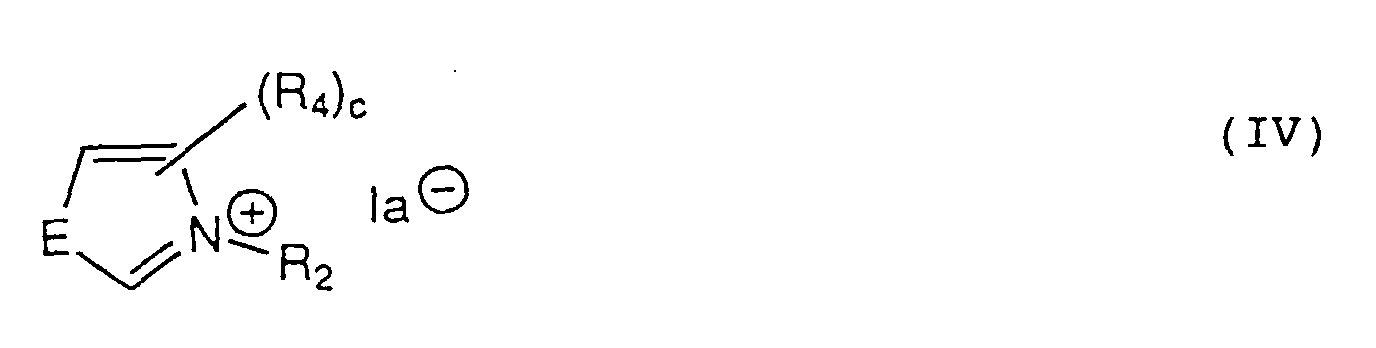
- The photo-electrochemical cell as in claim 1, wherein the semiconductor is a dye-sensitized particulate semiconductor.
Applications Claiming Priority (2)
| Application Number | Priority Date | Filing Date | Title |
|---|---|---|---|
| JP10272611A JP2000090991A (en) | 1998-09-09 | 1998-09-09 | Photoelectrochemical battery |
| JP27261198 | 1998-09-09 |
Publications (3)
| Publication Number | Publication Date |
|---|---|
| EP0986079A2 true EP0986079A2 (en) | 2000-03-15 |
| EP0986079A3 EP0986079A3 (en) | 2004-04-21 |
| EP0986079B1 EP0986079B1 (en) | 2006-04-12 |
Family
ID=17516353
Family Applications (1)
| Application Number | Title | Priority Date | Filing Date |
|---|---|---|---|
| EP99117116A Expired - Lifetime EP0986079B1 (en) | 1998-09-09 | 1999-08-31 | Photo-electrochemical cell |
Country Status (4)
| Country | Link |
|---|---|
| EP (1) | EP0986079B1 (en) |
| JP (1) | JP2000090991A (en) |
| AT (1) | ATE323318T1 (en) |
| DE (1) | DE69930805T2 (en) |
Cited By (22)
| Publication number | Priority date | Publication date | Assignee | Title |
|---|---|---|---|---|
| WO2002013216A1 (en) * | 2000-08-04 | 2002-02-14 | Siemens Axiva Gmbh & Co. Kg | Novel electrolytes for electrolytic capacitors and the use thereof |
| EP1075005A3 (en) * | 1999-08-04 | 2004-04-28 | Fuji Photo Film Co., Ltd. | Electrolyte composition, and photo-electro-chemical cell |
| EP1134759A3 (en) * | 2000-03-16 | 2004-12-29 | Fuji Photo Film Co., Ltd. | Electrolyte composition for photo-electrochemical cells |
| EP1507307A4 (en) * | 2002-05-20 | 2005-04-20 | Hitachi Maxell | PHOTOELECTRIC IMPLEMENTING DEVICE |
| WO2007093961A1 (en) | 2006-02-13 | 2007-08-23 | Ecole Polytechnique Federale De Lausanne (Epfl) | Ionic liquid electrolyte |
| EP2325913A1 (en) | 2006-03-23 | 2011-05-25 | Ecole Polytechnique Fédérale de Lausanne (EPFL) | A method for preparing a solar cell |
| WO2011085964A1 (en) | 2010-01-18 | 2011-07-21 | Merck Patent Gmbh | Electrolyte formulations |
| WO2011085967A1 (en) | 2010-01-18 | 2011-07-21 | Merck Patent Gmbh | Compounds containing perfluoroalkyl-cyano-alkoxy-borate anions or perfluoroalkyl-cyano-alkoxy-fluoro-borate anions |
| WO2011085965A1 (en) | 2010-01-18 | 2011-07-21 | Merck Patent Gmbh | Electrolyte formulations |
| EP2388853A1 (en) | 2010-05-20 | 2011-11-23 | Fundacion Cidetec | Ionic liquid based electrolytes containing sulfide/polysulfide redox couple and uses thereof |
| WO2012041437A2 (en) | 2010-09-30 | 2012-04-05 | Merck Patent Gmbh | Electrolyte formulations |
| WO2012048772A1 (en) | 2010-09-27 | 2012-04-19 | Merck Patent Gmbh | Functionalized fluoroalkyl fluorophosphate salts |
| WO2012076093A1 (en) | 2010-12-08 | 2012-06-14 | Merck Patent Gmbh | Additives for dye-sensitized solar cells |
| WO2012163490A1 (en) | 2011-05-31 | 2012-12-06 | Merck Patent Gmbh | Electrolyte formulations |
| EP2453516A4 (en) * | 2010-06-18 | 2013-01-16 | Sony Corp | PHOTOELECTRIC CONVERSION ELEMENT AND METHOD FOR PRODUCING THE SAME, AND ELECTRONIC DEVICE |
| WO2013010640A1 (en) | 2011-07-15 | 2013-01-24 | Merck Patent Gmbh | Compounds containing alkyl-alkoxy-cyano-borate anions |
| WO2013010641A1 (en) | 2011-07-15 | 2013-01-24 | Merck Patent Gmbh | Compounds containing alkyl-cyano-borate or alkyl-cyano-fluoroborate anions |
| WO2013026563A1 (en) | 2011-08-25 | 2013-02-28 | Merck Patent Gmbh | Additives for dye-sensitized solar cells |
| EP2883881A1 (en) | 2013-12-12 | 2015-06-17 | Merck Patent GmbH | Cobaltcomplex salts and mixtures of Cobaltcomplex salts for use in DSSC |
| EP1528580B2 (en) † | 2003-01-15 | 2015-07-01 | Nippon Shokubai Co., Ltd. | Dye-sensitized type solar cell |
| DE102013021029A1 (en) | 2013-12-17 | 2015-07-02 | Julius-Maximilians-Universität Würzburg | Cobalt complex salts |
| WO2017067631A1 (en) | 2015-10-23 | 2017-04-27 | Merck Patent Gmbh | Blue optoelectronic device |
Families Citing this family (8)
| Publication number | Priority date | Publication date | Assignee | Title |
|---|---|---|---|---|
| JP4493921B2 (en) * | 2003-02-13 | 2010-06-30 | 株式会社豊田中央研究所 | Dye-sensitized solar cell |
| JP4650257B2 (en) * | 2005-12-22 | 2011-03-16 | パナソニック電工株式会社 | Switch device |
| CN102265453B (en) | 2008-10-29 | 2014-10-01 | 富士胶片株式会社 | Dye, photoelectric conversion element using the same, photoelectrochemical cell, and method for producing the dye |
| JP5620081B2 (en) | 2009-09-28 | 2014-11-05 | 富士フイルム株式会社 | Method for manufacturing photoelectric conversion element |
| JP5524557B2 (en) | 2009-09-28 | 2014-06-18 | 富士フイルム株式会社 | Method for producing photoelectric conversion element, photoelectric conversion element, and photoelectrochemical cell |
| JP5614272B2 (en) | 2010-12-21 | 2014-10-29 | コニカミノルタ株式会社 | Photoelectric conversion element and dye-sensitized solar cell |
| JP5972811B2 (en) | 2013-02-22 | 2016-08-17 | 富士フイルム株式会社 | Photoelectric conversion element, method for producing photoelectric conversion element, and dye-sensitized solar cell |
| JP2015053149A (en) * | 2013-09-05 | 2015-03-19 | 富士フイルム株式会社 | Photoelectric conversion element, dye-sensitized solar cell, and back migration preventing agent of electron for photoelectric conversion element |
Family Cites Families (2)
| Publication number | Priority date | Publication date | Assignee | Title |
|---|---|---|---|---|
| WO1994005025A1 (en) * | 1992-08-17 | 1994-03-03 | Sandoz Ltd. | Use of optical brighteners and phthalocyanines as photosensitizers |
| WO1997002252A1 (en) * | 1995-06-30 | 1997-01-23 | Covalent Associates, Inc. | Hydrophobic ionic liquids |
-
1998
- 1998-09-09 JP JP10272611A patent/JP2000090991A/en active Pending
-
1999
- 1999-08-31 DE DE69930805T patent/DE69930805T2/en not_active Expired - Lifetime
- 1999-08-31 AT AT99117116T patent/ATE323318T1/en not_active IP Right Cessation
- 1999-08-31 EP EP99117116A patent/EP0986079B1/en not_active Expired - Lifetime
Cited By (28)
| Publication number | Priority date | Publication date | Assignee | Title |
|---|---|---|---|---|
| EP1075005A3 (en) * | 1999-08-04 | 2004-04-28 | Fuji Photo Film Co., Ltd. | Electrolyte composition, and photo-electro-chemical cell |
| EP1134759A3 (en) * | 2000-03-16 | 2004-12-29 | Fuji Photo Film Co., Ltd. | Electrolyte composition for photo-electrochemical cells |
| WO2002013216A1 (en) * | 2000-08-04 | 2002-02-14 | Siemens Axiva Gmbh & Co. Kg | Novel electrolytes for electrolytic capacitors and the use thereof |
| EP1507307A4 (en) * | 2002-05-20 | 2005-04-20 | Hitachi Maxell | PHOTOELECTRIC IMPLEMENTING DEVICE |
| EP1528580B2 (en) † | 2003-01-15 | 2015-07-01 | Nippon Shokubai Co., Ltd. | Dye-sensitized type solar cell |
| US8114318B2 (en) | 2006-02-13 | 2012-02-14 | Ecole Polytechnique Federale De Lausanne (Epfl) | Ionic liquid electrolyte |
| WO2007093961A1 (en) | 2006-02-13 | 2007-08-23 | Ecole Polytechnique Federale De Lausanne (Epfl) | Ionic liquid electrolyte |
| EP2325913A1 (en) | 2006-03-23 | 2011-05-25 | Ecole Polytechnique Fédérale de Lausanne (EPFL) | A method for preparing a solar cell |
| US8901340B2 (en) | 2010-01-18 | 2014-12-02 | Merck Patent Gmbh | Compounds containing perfluoroalkyl-cyano-alkoxy-borate anions or perfluoroalkyl-cyano-alkoxy-fluoro-borate anions |
| WO2011085965A1 (en) | 2010-01-18 | 2011-07-21 | Merck Patent Gmbh | Electrolyte formulations |
| WO2011085964A1 (en) | 2010-01-18 | 2011-07-21 | Merck Patent Gmbh | Electrolyte formulations |
| WO2011085967A1 (en) | 2010-01-18 | 2011-07-21 | Merck Patent Gmbh | Compounds containing perfluoroalkyl-cyano-alkoxy-borate anions or perfluoroalkyl-cyano-alkoxy-fluoro-borate anions |
| US8835667B2 (en) | 2010-01-18 | 2014-09-16 | Merck Patent Gmbh | Electrolyte formulations |
| WO2011144697A1 (en) | 2010-05-20 | 2011-11-24 | Fundacion Cidetec | Ionic liquid based electrolytes containing sulfide/polysulfide redox couple and uses thereof |
| EP2388853A1 (en) | 2010-05-20 | 2011-11-23 | Fundacion Cidetec | Ionic liquid based electrolytes containing sulfide/polysulfide redox couple and uses thereof |
| EP2453516A4 (en) * | 2010-06-18 | 2013-01-16 | Sony Corp | PHOTOELECTRIC CONVERSION ELEMENT AND METHOD FOR PRODUCING THE SAME, AND ELECTRONIC DEVICE |
| WO2012048772A1 (en) | 2010-09-27 | 2012-04-19 | Merck Patent Gmbh | Functionalized fluoroalkyl fluorophosphate salts |
| WO2012041437A2 (en) | 2010-09-30 | 2012-04-05 | Merck Patent Gmbh | Electrolyte formulations |
| WO2012076093A1 (en) | 2010-12-08 | 2012-06-14 | Merck Patent Gmbh | Additives for dye-sensitized solar cells |
| WO2012163490A1 (en) | 2011-05-31 | 2012-12-06 | Merck Patent Gmbh | Electrolyte formulations |
| WO2013010640A1 (en) | 2011-07-15 | 2013-01-24 | Merck Patent Gmbh | Compounds containing alkyl-alkoxy-cyano-borate anions |
| WO2013010641A1 (en) | 2011-07-15 | 2013-01-24 | Merck Patent Gmbh | Compounds containing alkyl-cyano-borate or alkyl-cyano-fluoroborate anions |
| WO2013026563A1 (en) | 2011-08-25 | 2013-02-28 | Merck Patent Gmbh | Additives for dye-sensitized solar cells |
| US9159499B2 (en) | 2011-08-25 | 2015-10-13 | Merck Patent Gmbh | Additives for dye-sensitized solar cells |
| US9390864B2 (en) | 2011-08-25 | 2016-07-12 | Merck Patent Gmbh | Additives for dye-sensitized solar cells |
| EP2883881A1 (en) | 2013-12-12 | 2015-06-17 | Merck Patent GmbH | Cobaltcomplex salts and mixtures of Cobaltcomplex salts for use in DSSC |
| DE102013021029A1 (en) | 2013-12-17 | 2015-07-02 | Julius-Maximilians-Universität Würzburg | Cobalt complex salts |
| WO2017067631A1 (en) | 2015-10-23 | 2017-04-27 | Merck Patent Gmbh | Blue optoelectronic device |
Also Published As
| Publication number | Publication date |
|---|---|
| DE69930805D1 (en) | 2006-05-24 |
| EP0986079A3 (en) | 2004-04-21 |
| EP0986079B1 (en) | 2006-04-12 |
| JP2000090991A (en) | 2000-03-31 |
| DE69930805T2 (en) | 2006-11-16 |
| ATE323318T1 (en) | 2006-04-15 |
Similar Documents
| Publication | Publication Date | Title |
|---|---|---|
| EP0986079B1 (en) | Photo-electrochemical cell | |
| US6495067B1 (en) | Liquid crystal compound, liquid crystal mixture or composition, electrolyte comprising the same, electrochemical cell and photo-electrochemical cell containing the electrolyte | |
| US6586670B2 (en) | Photoelectric conversion device and method for producing same | |
| JP4222466B2 (en) | Charge transport material, photoelectric conversion element and photovoltaic cell using the same, and pyridine compound | |
| EP0986080B1 (en) | Method for producing an electrolyte containing a crosslinked polymer and a photo-electrochemical cell using the electrolyte | |
| EP1083582B1 (en) | Dye sensitized photoelectrochemical cell | |
| US20020015881A1 (en) | Photoelectric conversion device and photo cell | |
| EP1176618B1 (en) | Ruthenium complex dye, photoelectric conversion device and photoelectric cell | |
| JP4443713B2 (en) | Semiconductor fine particles, photoelectric conversion element and photovoltaic cell | |
| JP4500420B2 (en) | Photoelectric conversion element and photovoltaic cell | |
| JP2002008741A (en) | Photoelectric conversion element and photocell | |
| JP2000319260A (en) | Liquid crystal compound, liquid crystal mixture, liquid crystal composition, electrolyte, electrochemical cell and photoelectrochemical cell | |
| JP4111360B2 (en) | Gel electrolyte, gel electrolyte for photoelectrochemical cell, and photoelectrochemical cell | |
| JP2003031270A (en) | Electrolyte composition, photoelectric conversion element and photocell | |
| JP4162116B2 (en) | Photoelectric conversion element and photoelectrochemical cell | |
| JP4763120B2 (en) | Photoelectric conversion element and photovoltaic cell using the same | |
| EP1385182B1 (en) | Pyridinium compounds and their use in a photoelectrochemical cell | |
| JP2003017148A (en) | Electrolyte component, photoelectric conversion element, and photoelectric chemical cell | |
| JP4772192B2 (en) | Photoelectric conversion element, photovoltaic cell and complex dye | |
| EP1017070B1 (en) | Photo-electrochemical cell | |
| JP2003100357A (en) | Method for manufacturing photoelectric conversion element, photoelectric conversion element and photovoltaic cell | |
| JP2000036332A (en) | Electrolyte, photoelectric conversion element, and photo-regenerative photo-electrochemical battery | |
| JP4578695B2 (en) | Method for creating photoelectric conversion element | |
| JP2000058891A (en) | Electrolyte, electrolyte for photoelectric chemical cell, photoelectric chemical battery and pyridinium compound | |
| JP4497395B2 (en) | Method for producing photoelectric conversion element and photoelectric conversion element |
Legal Events
| Date | Code | Title | Description |
|---|---|---|---|
| PUAI | Public reference made under article 153(3) epc to a published international application that has entered the european phase |
Free format text: ORIGINAL CODE: 0009012 |
|
| AK | Designated contracting states |
Kind code of ref document: A2 Designated state(s): AT BE CH CY DE DK ES FI FR GB GR IE IT LI LU MC NL PT SE |
|
| AX | Request for extension of the european patent |
Free format text: AL;LT;LV;MK;RO;SI |
|
| PUAL | Search report despatched |
Free format text: ORIGINAL CODE: 0009013 |
|
| AK | Designated contracting states |
Kind code of ref document: A3 Designated state(s): AT BE CH CY DE DK ES FI FR GB GR IE IT LI LU MC NL PT SE |
|
| AX | Request for extension of the european patent |
Extension state: AL LT LV MK RO SI |
|
| 17P | Request for examination filed |
Effective date: 20040615 |
|
| 17Q | First examination report despatched |
Effective date: 20040907 |
|
| AKX | Designation fees paid |
Designated state(s): AT BE CH CY DE DK ES FI FR GB GR IE IT LI LU MC NL PT SE |
|
| GRAP | Despatch of communication of intention to grant a patent |
Free format text: ORIGINAL CODE: EPIDOSNIGR1 |
|
| GRAS | Grant fee paid |
Free format text: ORIGINAL CODE: EPIDOSNIGR3 |
|
| GRAA | (expected) grant |
Free format text: ORIGINAL CODE: 0009210 |
|
| AK | Designated contracting states |
Kind code of ref document: B1 Designated state(s): AT BE CH CY DE DK ES FI FR GB GR IE IT LI LU MC NL PT SE |
|
| PG25 | Lapsed in a contracting state [announced via postgrant information from national office to epo] |
Ref country code: NL Free format text: LAPSE BECAUSE OF FAILURE TO SUBMIT A TRANSLATION OF THE DESCRIPTION OR TO PAY THE FEE WITHIN THE PRESCRIBED TIME-LIMIT Effective date: 20060412 Ref country code: LI Free format text: LAPSE BECAUSE OF FAILURE TO SUBMIT A TRANSLATION OF THE DESCRIPTION OR TO PAY THE FEE WITHIN THE PRESCRIBED TIME-LIMIT Effective date: 20060412 Ref country code: IT Free format text: LAPSE BECAUSE OF FAILURE TO SUBMIT A TRANSLATION OF THE DESCRIPTION OR TO PAY THE FEE WITHIN THE PRE;WARNING: LAPSES OF ITALIAN PATENTS WITH EFFECTIVE DATE BEFORE 2007 MAY HAVE OCCURRED AT ANY TIME BEFORE 2007. THE CORRECT EFFECTIVE DATE MAY BE DIFFERENT FROM THE ONE RECORDED.SCRIBED TIME-LIMIT Effective date: 20060412 Ref country code: FI Free format text: LAPSE BECAUSE OF FAILURE TO SUBMIT A TRANSLATION OF THE DESCRIPTION OR TO PAY THE FEE WITHIN THE PRESCRIBED TIME-LIMIT Effective date: 20060412 Ref country code: CH Free format text: LAPSE BECAUSE OF FAILURE TO SUBMIT A TRANSLATION OF THE DESCRIPTION OR TO PAY THE FEE WITHIN THE PRESCRIBED TIME-LIMIT Effective date: 20060412 Ref country code: BE Free format text: LAPSE BECAUSE OF FAILURE TO SUBMIT A TRANSLATION OF THE DESCRIPTION OR TO PAY THE FEE WITHIN THE PRESCRIBED TIME-LIMIT Effective date: 20060412 Ref country code: AT Free format text: LAPSE BECAUSE OF FAILURE TO SUBMIT A TRANSLATION OF THE DESCRIPTION OR TO PAY THE FEE WITHIN THE PRESCRIBED TIME-LIMIT Effective date: 20060412 |
|
| REG | Reference to a national code |
Ref country code: GB Ref legal event code: FG4D |
|
| REG | Reference to a national code |
Ref country code: CH Ref legal event code: EP |
|
| REF | Corresponds to: |
Ref document number: 69930805 Country of ref document: DE Date of ref document: 20060524 Kind code of ref document: P |
|
| REG | Reference to a national code |
Ref country code: IE Ref legal event code: FG4D |
|
| PG25 | Lapsed in a contracting state [announced via postgrant information from national office to epo] |
Ref country code: SE Free format text: LAPSE BECAUSE OF FAILURE TO SUBMIT A TRANSLATION OF THE DESCRIPTION OR TO PAY THE FEE WITHIN THE PRESCRIBED TIME-LIMIT Effective date: 20060712 Ref country code: DK Free format text: LAPSE BECAUSE OF FAILURE TO SUBMIT A TRANSLATION OF THE DESCRIPTION OR TO PAY THE FEE WITHIN THE PRESCRIBED TIME-LIMIT Effective date: 20060712 |
|
| PG25 | Lapsed in a contracting state [announced via postgrant information from national office to epo] |
Ref country code: ES Free format text: LAPSE BECAUSE OF FAILURE TO SUBMIT A TRANSLATION OF THE DESCRIPTION OR TO PAY THE FEE WITHIN THE PRESCRIBED TIME-LIMIT Effective date: 20060723 |
|
| PG25 | Lapsed in a contracting state [announced via postgrant information from national office to epo] |
Ref country code: MC Free format text: LAPSE BECAUSE OF NON-PAYMENT OF DUE FEES Effective date: 20060831 Ref country code: IE Free format text: LAPSE BECAUSE OF NON-PAYMENT OF DUE FEES Effective date: 20060831 |
|
| PG25 | Lapsed in a contracting state [announced via postgrant information from national office to epo] |
Ref country code: PT Free format text: LAPSE BECAUSE OF FAILURE TO SUBMIT A TRANSLATION OF THE DESCRIPTION OR TO PAY THE FEE WITHIN THE PRESCRIBED TIME-LIMIT Effective date: 20060912 |
|
| NLV1 | Nl: lapsed or annulled due to failure to fulfill the requirements of art. 29p and 29m of the patents act | ||
| REG | Reference to a national code |
Ref country code: CH Ref legal event code: PL |
|
| PLBE | No opposition filed within time limit |
Free format text: ORIGINAL CODE: 0009261 |
|
| STAA | Information on the status of an ep patent application or granted ep patent |
Free format text: STATUS: NO OPPOSITION FILED WITHIN TIME LIMIT |
|
| GBPC | Gb: european patent ceased through non-payment of renewal fee |
Effective date: 20060831 |
|
| EN | Fr: translation not filed | ||
| 26N | No opposition filed |
Effective date: 20070115 |
|
| RAP2 | Party data changed (patent owner data changed or rights of a patent transferred) |
Owner name: FUJIFILM CORPORATION |
|
| PG25 | Lapsed in a contracting state [announced via postgrant information from national office to epo] |
Ref country code: GB Free format text: LAPSE BECAUSE OF NON-PAYMENT OF DUE FEES Effective date: 20060831 |
|
| PG25 | Lapsed in a contracting state [announced via postgrant information from national office to epo] |
Ref country code: GR Free format text: LAPSE BECAUSE OF FAILURE TO SUBMIT A TRANSLATION OF THE DESCRIPTION OR TO PAY THE FEE WITHIN THE PRESCRIBED TIME-LIMIT Effective date: 20060713 Ref country code: FR Free format text: LAPSE BECAUSE OF FAILURE TO SUBMIT A TRANSLATION OF THE DESCRIPTION OR TO PAY THE FEE WITHIN THE PRESCRIBED TIME-LIMIT Effective date: 20070309 |
|
| PG25 | Lapsed in a contracting state [announced via postgrant information from national office to epo] |
Ref country code: LU Free format text: LAPSE BECAUSE OF NON-PAYMENT OF DUE FEES Effective date: 20060831 |
|
| PG25 | Lapsed in a contracting state [announced via postgrant information from national office to epo] |
Ref country code: FR Free format text: LAPSE BECAUSE OF FAILURE TO SUBMIT A TRANSLATION OF THE DESCRIPTION OR TO PAY THE FEE WITHIN THE PRESCRIBED TIME-LIMIT Effective date: 20060412 Ref country code: CY Free format text: LAPSE BECAUSE OF FAILURE TO SUBMIT A TRANSLATION OF THE DESCRIPTION OR TO PAY THE FEE WITHIN THE PRESCRIBED TIME-LIMIT Effective date: 20060412 |
|
| PGFP | Annual fee paid to national office [announced via postgrant information from national office to epo] |
Ref country code: DE Payment date: 20150825 Year of fee payment: 17 |
|
| REG | Reference to a national code |
Ref country code: DE Ref legal event code: R119 Ref document number: 69930805 Country of ref document: DE |
|
| PG25 | Lapsed in a contracting state [announced via postgrant information from national office to epo] |
Ref country code: DE Free format text: LAPSE BECAUSE OF NON-PAYMENT OF DUE FEES Effective date: 20170301 |