EP0986030B1 - Electronic coin selector - Google Patents
Electronic coin selector Download PDFInfo
- Publication number
- EP0986030B1 EP0986030B1 EP98118878A EP98118878A EP0986030B1 EP 0986030 B1 EP0986030 B1 EP 0986030B1 EP 98118878 A EP98118878 A EP 98118878A EP 98118878 A EP98118878 A EP 98118878A EP 0986030 B1 EP0986030 B1 EP 0986030B1
- Authority
- EP
- European Patent Office
- Prior art keywords
- coin
- data
- selector
- genuine
- key
- Prior art date
- Legal status (The legal status is an assumption and is not a legal conclusion. Google has not performed a legal analysis and makes no representation as to the accuracy of the status listed.)
- Expired - Lifetime
Links
Images


Classifications
-
- G—PHYSICS
- G07—CHECKING-DEVICES
- G07D—HANDLING OF COINS OR VALUABLE PAPERS, e.g. TESTING, SORTING BY DENOMINATIONS, COUNTING, DISPENSING, CHANGING OR DEPOSITING
- G07D5/00—Testing specially adapted to determine the identity or genuineness of coins, e.g. for segregating coins which are unacceptable or alien to a currency
Definitions
- This invention relates to a coin selector for sorting electronically coins which are currency. Especially, this invention relates to a coin selector which can change simply and store various data which relate to desired genuine coins. Furthermore, this invention relates to a key type electronic coin selector which can lock the memory of data which relate to genuine coins, concretely.
- the term "coin” in this specification includes small disc bodies, such as coins which are currency, medals or tokens for games.
- an electronic coin selector can not be simply changed into another desired genuine coin selector from the set genuine coin selector.
- the disadvantage of a conventional electronic coin selector as mentioned above is that one can not change the set genuine coin data into desired other genuine coin data in a simple way.
- Another disadvantage of a conventional electronic coin selector is that the genuine coin data can be changed by a person other than a manager in the same way.
- one disadvantage of a conventional electronic coin selector is that the security is not sufficient, since the warranty for the reliability and the safety, i.e., the security, is the same.
- EP 0 072 189 A discloses a coin validation apparatus as an electronic coin selector, comprising a coin testing section for detecting an inserted coin electronically to obtain data, a programmed memory for storing data relating to standard values of coins to be detected, and a programmed computer for comparing measured values of an inserted coin with computed reference values, to judge whether an inserted coin is a genuine coin.
- EP 0 602 474 A1, WO 97/46984 A1, and US 5 462 149 each disclose a method for determining calibration or validation data for coins to be detected as genuine or non-genuine.
- This invention was developed with the objective of eliminating the above-mentioned problems.
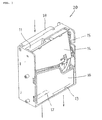
- a coin selector 20 according to an embodiment of this invention is shown in a schematic manner in Fig. 1.
- the selector 20 is of the slender box type.
- the top part of selector 20 provides the insertion opening 11 for coins.
- the bottom of selector 20 provides the accommodation opening 12 for receiving genuine coins in the inside of, for example, a game machine (not shown).
- selector 20 provides the return opening 13 for discharging dummy coins etc. out of the game machine.
- the fairly large trapezoid board shown in the upper part of Fig. 1 is a door 14.
- the door 14 is pivotable by means of a pivot axis 15 shown at the right-hand side in Fig. 1, and is usually closed with a spring (not shown).
- the trapezoid board shown below in Fig. 1 is a cover 16, which is removably fixed to the selector 20.
- the horizontal-direction J type lever 18 made from resin is pivoted at the nearly central part in the upper part of Fig. 1.
- the coin which is input through the insertion opening 11 performs a natural drop in a diagonal path (not shown) formed inside selector 20.
- the coin which performs the natural drop is detected by three pairs of coils 21, 22, and 23 (refer to Fig. 2) arranged inside of the upper part of selector 20.
- a solenoid 24 (refer to Fig. 2) in the lower-part inside selector 20 is switched on.
- the dropped genuine coin is contained in the cash box (not shown) for genuine coins installed inside the game machine.
- a signal S indicating the detecting of a coin is output from a sensor 25 (refer to Fig. 2) arranged in selector 20 near accommodation opening 12.
- the solenoid 24 is switched off by the detecting-signal S and the gate for the diagonal paths is closed.
- Fig. 2 is a block diagram of the electronic circuit built in the selector 20 of Fig. 1.
- the coil 21 for a detection detects the material of the inserted coin.
- the coil 21 for a detection is connected to an oscillation circuit 26 of a comparatively low frequency.
- the coil 22 for a detection detects thickness of the inserted coin.
- the coil 22 for a detection is connected to an oscillation circuit 27 of a comparatively high frequency.
- the coil 23 for a detection detects the diameter of the inserted coin.
- the coil 23 for a detection is connected to an oscillation circuit 28 of a comparatively high frequency.
- Each signal from oscillation circuits 26-28 is rectified by a corresponding one of rectifier circuits 31, 32, and 33 containing detection means.
- the reference number 34 in the center of Fig. 2 indicates a circuit which converts an analog signal to a digital signal.
- the converting circuit 34 respectively performs the sampling of the analog signal from each of rectifier circuits 31-33, and converts it to a digital signal, and outputs the digital signals.
- a signal-processing unit 35 is a CPU or a microcomputer concretely, and processes a digital signal.
- a memory 36 stores various data, and the memory 36 of the embodiment stores key data 41 which relate to a coin type key, i.e., a key which is formed like a coin.
- the key data 41 are input into the signal-processing unit 35 from external through an input terminal 37, for example, and are stored in the memory 36.
- the key data 41 is desirably stored in the memory 36 previously.
- the coin type key used is concretely a medal of silver, a medal of gold, a special alloy medal, a magnetic medal, etc.
- a memory 36 may store various genuine coin data 42 which relate to inserted genuine coins as mentioned below.
- a reference symbol MS on the right-hand side of the center in Fig. 2 is a switch for mode selections.
- the switch MS chooses either a storing mode for a genuine coin data 42 in memory 36 or an operating mode of selector 20.
- Switch 500S is for setting a genuine coin data 42 of a coin of 500 yen.
- the switch 500S is on, the coin data of a coin of 500 yen is stored in a memory area 42.
- Switch 100S is for setting a genuine coin data 42 of a coin of 100 yen.
- the coin data of a coin of 100 yen is stored in memory area 42.
- switch 50S is for setting the coin data 42 of a coin of 50 yen
- switch 10S is for setting the coin data 42 of a coin of 10 yen.
- a signal 100 is output to a game machine etc. in the selector operation mode, when the inserted coin is a genuine coin of 100 yen.
- a signal 50 is output to a game machine etc., when the inserted coin is a genuine coin of 50 yen.
- a signal 10 is output to a game machine etc., when the inserted coin is a genuine coin of 10 yen.
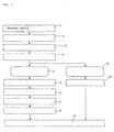
- Fig. 3 is a flowchart for explaining an operation of Fig. 2.
- the initialization of the selector 20 is automatically performed (step 52).
- the selecting switch MS for modes is used to choose the data production/memory mode, and the coin type setting switch 100S for coins of 100 yen is chosen or switched on.
- Step 70 when the coin type key is judged to be genuine, i.e. to be the correct key coin, a data production mode will be performed. (Step 70).
- step 54 if a coin of 100 yen is inserted into the insertion opening 11 (step 54), the number of inserted 100 yen coins will be counted "one" (step 55).
- sampling data of the inserted coin of 100 yen are obtained (step 56) by means of coils 21 to 23, and so on.
- the coin data 42 of a coin of 100 yen will be statistically processed by the signal-processing unit 35 (step 58).
- the 100 yen coin data 42 are stored into the memory 36 (step 59).
- the modification switch MS is used to choose the collector mode of the electronic coin selector 20 after the above-mentioned preparation.
- step 61 If a coin is inserted into the insertion opening 11 in the above-mentioned situation (step 61), the data of the inserted coin will be obtained by the sampling (step 62).
- the sampling data of the inserted coin are compared with the 100 yen coin data 42 of memory 36 (step 63).
- step 65 When the sampling data of coin coincides with the coin data 42 of a coin of 100 yen, it is judged that the coin is genuine (step 65).
- the solenoid 24 for the gate for receiving a genuine coin is switched on (step 66).
- the genuine coin passes through the sensor 25 (step 67), and the solenoid 24 for the gate for receiving a genuine coin turns off (step 68).
- the signal 100 for a genuine 100 yen coin shown in Fig. 2 is simultaneously output (step 69).
- the game machine which is equipped with the electronic coin selector 20 gets into the situation in which a game is possible.
- Fig. 4 is a perspective diagram showing another embodiment of this invention.
- Fig. 5 is a block circuit diagram built into Fig. 4.
- Fig. 6 is a flowchart for explaining an operation of Fig. 5.
- the collector shown in Fig. 4 is equipped with almost the same components as the collector of Fig. 1. Therefore, the same parts have the same reference numbers.
- a coin C which is input through the insertion opening 11 drops naturally the perpendicular path (not shown) formed inside selector 20.
- the coin C which performs a natural drop is detected by three coils 21, 22 and 23 (refer to Fig. 5) arranged in the upper part of selector 20.
- the detected coin C is judged by the block circuit of Fig. 5 as after-mentioned whether it is genuine.
- gate GT (refer to Fig. 5) for a perpendicular path opens.
- a signal S indicating a coin detection is output from the sensor 25 (refer to Fig. 5) arranged in the selector 20 near the accommodation opening.
- the solenoid 24 is turned off through the detecting-signal S and gate GT for a perpendicular path is closed.
- the dummy coin FC drops from a return opening (not shown) through a diagonal path (illustration abridging).
- the dummy coin FC is discharged out of the game machine.
- Fig. 5 is a block diagram of the electronic circuit built in the selector 20 of Fig. 4.
- the coils 21-23 for a detection respectively detect the material, the thickness and the diameter of the inserted coin.
- the coils 21-23 for a detection are respectively connected to oscillation circuits 26-28.
- Each signal from oscillation circuits 26-28 respectively is rectified by the corresponding end of rectifier circuits 31-33 through detector circuits D1, D2, D3.
- a converting circuit 34 respectively performs the sampling of the analog signals from each of rectifier circuits 31-33, and converts it to a digital signal, and outputs the signals.
- the signal-processing unit 35 processes the digital signals.
- a memory 36 stores key data 41 which relate to the coin type key.
- the key data 41 are input into the signal-processing unit 35 by an external, through an input terminal 37 for setting a key coin, and are stored in the memory 36.
- the key data 41 are previously stored in the memory 36. Furthermore, the memory 36 stores various coin data 42 which relate to the inserted genuine coins after-mentioned.
- the switch MS for selecting mode chooses whether a coin data 42 is either stored in memory 36 or an ussual operation of selector 20 is performed.
- a setting means ST for coin type to be accepted is a plurality of switches 500S, 100S, 50S, and 10S (not shown) as shown in Fig. 2, concretely.
- switch 500S is for setting the coin data 42 of a coin of 500 yen, and for storing the coin data of a coin of 500 yen in the memory 36.
- switch 100S is for setting the coin data 42 of a coin of 100 yen, and for storing the coin data 42 of a coin of 100 yen.
- Switch 50S is for setting the coin data 42 of a coin of 50 yen, and for storing the coin data of a coin of 50 yen.
- the signal 500 on the right-hand side of the center in Fig. 5 is output when the inserted coin is a genuine coin of 500 yen.
- a signal 100 is output when the inserted coin is a genuine coin of 100 yen.
- a signal 50 is output when the inserted coin is a genuine coin of 50 yen.
- a signal 10 is output when the inserted coin is a genuine coin of 10 yen.
- Fig. 6 is a flowchart for explaining an operation of Fig. 5.
- the power supply switch (not shown) of selector 20 is switched on, and then the operation starts (step 51).
- the initialization of the selector 20 is automatically performed (step 52).
- this diagram describes the case in which the selector 20 is used for an exclusive use of 50 yen coins, for example.
- the mode selecting switch MS is used to choose the data production/memory mode. And the switch for the 50 yen coin type of the setting means ST (not shown) is actuated.
- step 57 This operation is repeated until coins of 50 yen are continuously inserted into the insertion opening 11 to a total number of inserted coins which reaches a predetermined number (step 57), for example sixteen coins or sixteen times of insertion of 50 yen coins.
- the coin data 42 of the coins of 50 yen will be statistically processed by the signal-processing unit 35 (step 58).
- the electronic coin selector 20 chooses the selector mode of the switch MS and is used in the selector mode.
- step 61 If a coin is inserted into the insertion opening 11 in the above-mentioned situation (step 61), the data of the inserted coin will be obtained by the sampling.
- sampling data of the inserted coin are compared with the 50 yen coin data 42 of memory 36.
- the coin is judged to be genuine (step 65).
- the signal 50 for a genuine coin shown in Fig. 5 is output simultaneously (step 69).
- the game machine (not shown) equipped with the electronic coin selector 20, by the output of the genuine coin, comes into the situation in which a game is possible.
- the first example of Fig. 1 and the second example of Fig. 4 explain a key-locking function which respectively relates to the data modification for a genuine coin.
- the key-locking function of the electronic coin selector which uses the coin key according to this invention is not limited to an above-mentioned example.
- the number data for an identification of the selector 20 can respectively be stored in the memory 36.
- an accumulation process of the accumulation number of sheets of time data and genuine coin etc. is performed for every output of genuine coin 100 and 50. And, the result can be stored in the memory 36.
- data can also be obtained only by a coin type key being inserted into the selector arranged to the game machine, for example.
- Fig. 7 is a flowchart for explaining another operation of the device of Fig. 5.
- a program switch e.g. the mode switching means MS and a key coin setting means 37 are turned on for equal to or more than 3 seconds.
- step 72 the orange of a LED (not shown) blinks.
- step 73 the program switch, i.e. the mode switching means MS and key coin setting means 37 are made off.
- step 70 a registered coin-shaped key is inserted.
- step 74 it is confirmed that the inserted coin is registered on as the coin-shaped key.
- step 75 the red and green of LED are alternatively blinking.
- step 76 a new coin-shaped key is inserted four times or 16 times.
- step 77 the green of LED is lit up.
- step 78 the data of the new coin-shaped key is registered and the change of registration data is completed.
- step 79 a coin sorting-out mode is chosen.
- step 81 it is confirmed that the inserted coin is not registered on as the coin-shaped key.
- step 82 the green of LED is lit up.
- the genuine coin data in an electronic coin selector can be simply changed into another desired genuine coin, only by inserting key coin, by adding a simple component.
Landscapes
- Physics & Mathematics (AREA)
- General Physics & Mathematics (AREA)
- Testing Of Coins (AREA)
- Slot Machines And Peripheral Devices (AREA)
Description
- This invention relates to a coin selector for sorting electronically coins which are currency. Especially, this invention relates to a coin selector which can change simply and store various data which relate to desired genuine coins. Furthermore, this invention relates to a key type electronic coin selector which can lock the memory of data which relate to genuine coins, concretely. In addition, the term "coin" in this specification includes small disc bodies, such as coins which are currency, medals or tokens for games.
- Hitherto, various coin selectors were developed.
- For example, Japanese Patent Application No. 9-213789 which the applicant filed previously describes an electronic coin selector.
- Conventionally, this variety of electronic coin selectors can not store simply the various data which relate to desired genuine coins.
- In other words, an electronic coin selector can not be simply changed into another desired genuine coin selector from the set genuine coin selector.
- Therefore, the disadvantage of a conventional electronic coin selector as mentioned above is that one can not change the set genuine coin data into desired other genuine coin data in a simple way.
- Concretely, another disadvantage of a conventional electronic coin selector is that the genuine coin data can be changed by a person other than a manager in the same way.
- That is, one disadvantage of a conventional electronic coin selector is that the security is not sufficient, since the warranty for the reliability and the safety, i.e., the security, is the same.
- EP 0 072 189 A discloses a coin validation apparatus as an electronic coin selector, comprising a coin testing section for detecting an inserted coin electronically to obtain data, a programmed memory for storing data relating to standard values of coins to be detected, and a programmed computer for comparing measured values of an inserted coin with computed reference values, to judge whether an inserted coin is a genuine coin.
- EP 0 602 474 A1, WO 97/46984 A1, and US 5 462 149 each disclose a method for determining calibration or validation data for coins to be detected as genuine or non-genuine.
- This invention was developed with the objective of eliminating the above-mentioned problems.
- This object is achieved by an electronic coin selector as claimed in claim 1.
- Further developments of the invention are given in the dependent claims.
- Further features and advantages follow from the following examples referring to the appending drawings, of which:
- Fig. 1 is a perspective diagram showing one example according to this invention;
- Fig. 2 is a block circuit diagram of a control device built into the device of Fig. 1;
- Fig. 3 is a flowchart for explaining an operation of the device of Fig. 2;
- Fig. 4 is a perspective diagram showing another example of this invention;
- Fig. 5 is a block circuit diagram of a control device built into the device of Fig. 4;
- Fig. 6 is a flowchart for explaining an operation of Fig. 5; and
- Fig. 7 is a flowchart for explaining another operation of the device of Fig. 5.
-
- A
coin selector 20 according to an embodiment of this invention is shown in a schematic manner in Fig. 1. - The
selector 20 is of the slender box type. The top part ofselector 20 provides the insertion opening 11 for coins. - The bottom of
selector 20 provides the accommodation opening 12 for receiving genuine coins in the inside of, for example, a game machine (not shown). - And, the bottom of
selector 20 provides the return opening 13 for discharging dummy coins etc. out of the game machine. - The fairly large trapezoid board shown in the upper part of Fig. 1 is a
door 14. - The
door 14 is pivotable by means of apivot axis 15 shown at the right-hand side in Fig. 1, and is usually closed with a spring (not shown). The trapezoid board shown below in Fig. 1 is acover 16, which is removably fixed to theselector 20. - The horizontal-direction
J type lever 18 made from resin is pivoted at the nearly central part in the upper part of Fig. 1. - In addition, although omitted for details, when the
lever 18 is pushed downward, thedoor 14 is opened and a dummy coin from inside ofselector 20 is returned through thereturn opening 13. - Here, when a coin is inserted into the
selector 20, the usual operation of the selector is as follows. - First, the coin which is input through the
insertion opening 11 performs a natural drop in a diagonal path (not shown) formed insideselector 20. - The coin which performs the natural drop is detected by three pairs of
coils selector 20. - It is judged whether the inserted coin is genuine or not by means of the circuit shown in Fig. 2 as after-mentioned.
- When the coin is judged to be genuine, a solenoid 24 (refer to Fig. 2) in the lower-part inside
selector 20 is switched on. - When the
solenoid 24 is operated, the gate for the diagonal path (not shown) opens. - Therefore, the genuine coin drops through the accommodation opening 12 of
selector 20. - The dropped genuine coin is contained in the cash box (not shown) for genuine coins installed inside the game machine.
- In addition, at this time, a signal S indicating the detecting of a coin is output from a sensor 25 (refer to Fig. 2) arranged in
selector 20 nearaccommodation opening 12. - The
solenoid 24 is switched off by the detecting-signal S and the gate for the diagonal paths is closed. - When the inserted coin is judged to be a dummy coin, the
solenoid 24 does not operate. For this reason, the gate for the diagonal path is kept closed. - Therefore, a dummy coin drops from the return opening 13 through an under path (not shown).
- In other words, a dummy coin is discharged out of the game machine.
- Fig. 2 is a block diagram of the electronic circuit built in the
selector 20 of Fig. 1. - The
coil 21 for a detection detects the material of the inserted coin. - The
coil 21 for a detection is connected to anoscillation circuit 26 of a comparatively low frequency. - The
coil 22 for a detection detects thickness of the inserted coin. Thecoil 22 for a detection is connected to anoscillation circuit 27 of a comparatively high frequency. - The
coil 23 for a detection detects the diameter of the inserted coin. Thecoil 23 for a detection is connected to anoscillation circuit 28 of a comparatively high frequency. - Each signal from oscillation circuits 26-28 is rectified by a corresponding one of
rectifier circuits - The
reference number 34 in the center of Fig. 2 indicates a circuit which converts an analog signal to a digital signal. - The converting
circuit 34 respectively performs the sampling of the analog signal from each of rectifier circuits 31-33, and converts it to a digital signal, and outputs the digital signals. - A signal-
processing unit 35 is a CPU or a microcomputer concretely, and processes a digital signal. - A
memory 36 stores various data, and thememory 36 of the embodiment storeskey data 41 which relate to a coin type key, i.e., a key which is formed like a coin. - The
key data 41 are input into the signal-processing unit 35 from external through aninput terminal 37, for example, and are stored in thememory 36. - The
key data 41, in other words, is desirably stored in thememory 36 previously. - In addition, the coin type key used is concretely a medal of silver, a medal of gold, a special alloy medal, a magnetic medal, etc.
- Furthermore, a
memory 36 may store variousgenuine coin data 42 which relate to inserted genuine coins as mentioned below. - A reference symbol MS on the right-hand side of the center in Fig. 2 is a switch for mode selections.
- The switch MS chooses either a storing mode for a
genuine coin data 42 inmemory 36 or an operating mode ofselector 20. -
Switch 500S is for setting agenuine coin data 42 of a coin of 500 yen. When theswitch 500S is on, the coin data of a coin of 500 yen is stored in amemory area 42. -
Switch 100S is for setting agenuine coin data 42 of a coin of 100 yen. When theswitch 100S is on, the coin data of a coin of 100 yen is stored inmemory area 42. - Similarly, switch 50S is for setting the
coin data 42 of a coin of 50 yen, and switch 10S is for setting thecoin data 42 of a coin of 10 yen. - In the operation mode of
selector 20, when the inserted coin is a genuine coin of 500 yen, asignal 500 on the right-hand side in the upper part of Fig. 2 is output to a game machine etc.. - Similarly, a
signal 100 is output to a game machine etc. in the selector operation mode, when the inserted coin is a genuine coin of 100 yen. - A
signal 50 is output to a game machine etc., when the inserted coin is a genuine coin of 50 yen. Asignal 10 is output to a game machine etc., when the inserted coin is a genuine coin of 10 yen. - Fig. 3 is a flowchart for explaining an operation of Fig. 2.
- When the power supply switch (not shown) of
selector 20 is switched ON, the operation starts (step 51). - At the start of the operation the initialization of the
selector 20 is automatically performed (step 52). - As to an initialization concretely the checks of whether the
solenoid 24 of the gate operates normally and whether thesensor 25 operates normally are done automatically. - The case in which the
selector 20 is only used for 100 yen coins is described as follows: - In this case, first, the selecting switch MS for modes is used to choose the data production/memory mode, and the coin
type setting switch 100S for coins of 100 yen is chosen or switched on. - Therefore, if
initialization step 52 is completed, a data production mode will be chosen bymode confirmation step 53. - In this situation, if the coin type key is inserted into opening 11 of
selector 20, the data of the key coin and thekey data 41 ofmemory 36 will be compared. - As a result of the comparison, when the coin type key is judged to be genuine, i.e. to be the correct key coin, a data production mode will be performed. (Step 70).
- That is, if a coin of 100 yen is inserted into the insertion opening 11 (step 54), the number of inserted 100 yen coins will be counted "one" (step 55).
- And, the sampling data of the inserted coin of 100 yen are obtained (step 56) by means of
coils 21 to 23, and so on. - Above-mentioned operating is repeated and coins of 100 yen are continuously inserted into the
insertion opening 11 until the total number of inserted coins reaches a predetermined number N (fromstep 57 to step 54), for example 16, i.e. sixteen times of 100 yen coin insertion. - If the predetermined number N is reached, the
coin data 42 of a coin of 100 yen will be statistically processed by the signal-processing unit 35 (step 58). - And, the 100
yen coin data 42 are stored into the memory 36 (step 59). - The modification switch MS is used to choose the collector mode of the
electronic coin selector 20 after the above-mentioned preparation. - If a coin is inserted into the
insertion opening 11 in the above-mentioned situation (step 61), the data of the inserted coin will be obtained by the sampling (step 62). - The sampling data of the inserted coin are compared with the 100
yen coin data 42 of memory 36 (step 63). - When the sampling data of coin coincides with the
coin data 42 of a coin of 100 yen, it is judged that the coin is genuine (step 65). - When the 100 yen coin is judged to be genuine, the
solenoid 24 for the gate for receiving a genuine coin is switched on (step 66). - The genuine coin passes through the sensor 25 (step 67), and the
solenoid 24 for the gate for receiving a genuine coin turns off (step 68). - The
signal 100 for a genuine 100 yen coin shown in Fig. 2 is simultaneously output (step 69). - In addition, when the
signal 100 for a genuine 100 yen coin is output, the game machine which is equipped with theelectronic coin selector 20 gets into the situation in which a game is possible. - Fig. 4 is a perspective diagram showing another embodiment of this invention.
- Fig. 5 is a block circuit diagram built into Fig. 4.
- Fig. 6 is a flowchart for explaining an operation of Fig. 5.
- In addition, the collector shown in Fig. 4 is equipped with almost the same components as the collector of Fig. 1. Therefore, the same parts have the same reference numbers.
- An operation in which a coin is inserted into the
selector 20 is explained simply as follows. - A coin C which is input through the
insertion opening 11 drops naturally the perpendicular path (not shown) formed insideselector 20. - The coin C which performs a natural drop is detected by three
coils selector 20. - And, the detected coin C is judged by the block circuit of Fig. 5 as after-mentioned whether it is genuine.
- When the coin is judged to be genuine, the solenoids 24 (refer to Fig. 5) for a gate drive which exists down inside the
selector 20 is switched on. - When the
solenoid 24 operates, gate GT (refer to Fig. 5) for a perpendicular path opens. - Therefore, genuine coin TC drops perpendicularly and passes along the accommodation opening (not shown) of
selector 20. - Genuine coin TC which dropped perpendicularly is contained in the cash box (not shown) for genuine coins installed inside the game machine.
- In addition, at this time, a signal S indicating a coin detection is output from the sensor 25 (refer to Fig. 5) arranged in the
selector 20 near the accommodation opening. - The
solenoid 24 is turned off through the detecting-signal S and gate GT for a perpendicular path is closed. - When the inserted coin is judged to be a dummy coin, the
solenoid 24 does not operate. For this reason, slanting gate GT in the perpendicular path maintains a closed situation. - Therefore, the dummy coin FC drops from a return opening (not shown) through a diagonal path (illustration abridging).
- In other words, the dummy coin FC is discharged out of the game machine.
- Fig. 5 is a block diagram of the electronic circuit built in the
selector 20 of Fig. 4. - The coils 21-23 for a detection respectively detect the material, the thickness and the diameter of the inserted coin. The coils 21-23 for a detection are respectively connected to oscillation circuits 26-28.
- Each signal from oscillation circuits 26-28 respectively is rectified by the corresponding end of rectifier circuits 31-33 through detector circuits D1, D2, D3.
- A converting
circuit 34 respectively performs the sampling of the analog signals from each of rectifier circuits 31-33, and converts it to a digital signal, and outputs the signals. - The signal-processing
unit 35 processes the digital signals. - A
memory 36 storeskey data 41 which relate to the coin type key. - For example, the
key data 41 are input into the signal-processingunit 35 by an external, through aninput terminal 37 for setting a key coin, and are stored in thememory 36. - In other words, it is desirable that the
key data 41 are previously stored in thememory 36. Furthermore, thememory 36 storesvarious coin data 42 which relate to the inserted genuine coins after-mentioned. - The switch MS for selecting mode chooses whether a
coin data 42 is either stored inmemory 36 or an ussual operation ofselector 20 is performed. - A setting means ST for coin type to be accepted is a plurality of
switches - As explained in Fig. 2, switch 500S is for setting the
coin data 42 of a coin of 500 yen, and for storing the coin data of a coin of 500 yen in thememory 36. - Similarly, switch 100S is for setting the
coin data 42 of a coin of 100 yen, and for storing thecoin data 42 of a coin of 100 yen.Switch 50S is for setting thecoin data 42 of a coin of 50 yen, and for storing the coin data of a coin of 50 yen. - The
signal 500 on the right-hand side of the center in Fig. 5 is output when the inserted coin is a genuine coin of 500 yen. Asignal 100 is output when the inserted coin is a genuine coin of 100 yen. - Similarly, a
signal 50 is output when the inserted coin is a genuine coin of 50 yen. Asignal 10 is output when the inserted coin is a genuine coin of 10 yen. - Fig. 6 is a flowchart for explaining an operation of Fig. 5. The power supply switch (not shown) of
selector 20 is switched on, and then the operation starts (step 51). - At the start of the operation, the initialization of the
selector 20 is automatically performed (step 52). - Below, this diagram describes the case in which the
selector 20 is used for an exclusive use of 50 yen coins, for example. - In this case, the mode selecting switch MS is used to choose the data production/memory mode. And the switch for the 50 yen coin type of the setting means ST (not shown) is actuated.
- Therefore, if
initialization step 52 is completed, a data production mode will be chosen bymode confirmation step 53. - In this situation, if a coin type key is inserted into the
insertion opening 11 ofselector 20, the data of the key coin and thekey data 41 ofmemory 36 will be compared. - As a result of this comparison, when the coin type key is judged to be genuine, a data production mode is executed (step 70).
- That is, if a coin of 50 yen is inserted into the
insertion opening 11, the number of inserted 50 yen coins will be counted "one", and the sampling data of a coin of 50 yen will be obtained. - This operation is repeated until coins of 50 yen are continuously inserted into the
insertion opening 11 to a total number of inserted coins which reaches a predetermined number (step 57), for example sixteen coins or sixteen times of insertion of 50 yen coins. - If the predetermined number of coins is reached, the
coin data 42 of the coins of 50 yen will be statistically processed by the signal-processing unit 35 (step 58). - And, the
coin data 42 are stored into thememory 36. - After above-mentioned preparation, the
electronic coin selector 20 chooses the selector mode of the switch MS and is used in the selector mode. - If a coin is inserted into the
insertion opening 11 in the above-mentioned situation (step 61), the data of the inserted coin will be obtained by the sampling. - The sampling data of the inserted coin are compared with the 50
yen coin data 42 ofmemory 36. - When the sampling data of the inserted coin coincide with the
coin data 42 of a coin of 50 yen, the coin is judged to be genuine (step 65). - When the coin is judged to be genuine, the
solenoid 24 of gate GT is switched on, and genuine coin TC drops perpendicularly. - If the dropping genuine coin TC passes the
sensor 25, thesolenoid 24 of gate GT will be turned off. It will return to an original situation (step 68). - The
signal 50 for a genuine coin shown in Fig. 5 is output simultaneously (step 69). - In addition, the game machine (not shown) equipped with the
electronic coin selector 20, by the output of the genuine coin, comes into the situation in which a game is possible. - The first example of Fig. 1 and the second example of Fig. 4 explain a key-locking function which respectively relates to the data modification for a genuine coin.
- However, the key-locking function of the electronic coin selector which uses the coin key according to this invention is not limited to an above-mentioned example.
- For example, the number data for an identification of the
selector 20, the accumulation data of genuine coins, time data, etc. can respectively be stored in thememory 36. - And, an accumulation process of the accumulation number of sheets of time data and genuine coin etc. is performed for every output of
genuine coin memory 36. - Furthermore, data can also be obtained only by a coin type key being inserted into the selector arranged to the game machine, for example.
- Consequently, it can be simply investigated immediately what quantity of coins is inserted into the coin cash box inside the game machine by an external.
- In other words, moreover, the sales sum of each charged game machine can be simply investigated immediately, that is, how many coins have been inserted.
- Fig. 7 is a flowchart for explaining another operation of the device of Fig. 5.
- That is, the case to change the registered
key data 41 about the coin-shaped key is shown. - In
step 71, a program switch, e.g. the mode switching means MS and a key coin setting means 37 are turned on for equal to or more than 3 seconds. - In
step 72, the orange of a LED (not shown) blinks. - In
step 73, the program switch, i.e. the mode switching means MS and key coin setting means 37 are made off. - In
step 70, a registered coin-shaped key is inserted. - In
step 74, it is confirmed that the inserted coin is registered on as the coin-shaped key. - In
step 75, the red and green of LED are alternatively blinking. - In
step 76, a new coin-shaped key is inserted four times or 16 times. - In
step 77, the green of LED is lit up. - In
step 78, the data of the new coin-shaped key is registered and the change of registration data is completed. - In
step 79, a coin sorting-out mode is chosen. - In
step 81, it is confirmed that the inserted coin is not registered on as the coin-shaped key. - In
step 82, the green of LED is lit up. - As mentioned above, by this invention the genuine coin data in an electronic coin selector can be simply changed into another desired genuine coin, only by inserting key coin, by adding a simple component.
- In other words, a person except a manager can not change the genuine coin data in an electronic coin selector. Therefore, security, such as the reliability, the safety, etc. of a selector, improves greatly.
-
- 20:
- Electronic coin selector.
- --
- means for storing key data.
- 36:
- memory.
- 41:
- key data,
- --
- means for obtaining the data of coin,
- 21, 22, and 23:
- sensing coil,
- 26, 27, and 28:
- oscillation circuit,
- 31, 32, and 33:
- rectifier circuit,
- 34:
- converting circuit,
- 35:
- signal-processing unit,
- --
- means for judging whether it is key coin,
- 35:
- signal-processing unit
- 36:
- memory, and
- 41:
- key data.
-
- step 51:
- start,
- step 52:
- initial setting,
- step 53:
- mode confirmation (selection),
- step 70:
- coin-type key inserted,
- step 54:
- coin inserted,
- step 55:
- counting of inserted coin,
- step 56:
- sampling of coin data,
- step 57:
- number of inserted coin N=n,
- step 58:
- statistically processing of data,
- step 59:
- data stored in memory.
- step 61:
- coin inserted,
- step 62:
- sampling of coin data,
- step 63:
- comparing with data in memory,
- step 65:
- genuine coin?
- step 66:
- accept gate on,
- step 67:
- sensor passed?
- step 68:
- accept gate off, and
- step 69:
- genuine coin signal output.
-
- step 51:
- start,
- step 52:
- initial setting,
- step 53:
- mode confirmation (selection),
- step 61:
- coin inserted,
- step 65:
- genuine coin?
- step 68:
- gate operation,
- step 69:
- signal output,
- step 70:
- coin-type key?
- step 57:
- coin data collection, and
- step 58:
- processing of data for coin selection.
Claims (4)
- An electronic coin selector, comprising at least: detecting means (21, 22, 23) for detecting an inserted coin electronically to obtain data,detecting means (21, 22, 23) for detecting an inserted coin electronically to obtain data,memory means (36) for storing data (41,42) including key data (41) which relate to a key in the form of a coin, said key allowing access to at least somme of the data (41,42) stored in said memory means (36), andcomparing means (35) for comparing the data of the inserted coin and the key data (41) to judge whether the inserted coin is a key coin.
- The electronic coin selector as claimed in claim 1, wherein the key data (41) are previously stored in the memory means (36).
- The electronic coin selector as claimed in claim 1 or 2, further comprising memory means (36) for storing coin data (42) which relate to genuine coins to be inserted and changing means (MS, ST) for changing the coin data (42) when the inserted coin is judged to be the key coin.
- The electronic coin selector according to one of claims 1 to 3, further comprising changing means (37, MS, 35) for changing the key data (41) stored in the memory means (36).
Applications Claiming Priority (3)
| Application Number | Priority Date | Filing Date | Title |
|---|---|---|---|
| JP23483698A JP4171828B2 (en) | 1998-07-16 | 1998-07-16 | Standard data creation method for electronic coin selector |
| JP23483698 | 1998-07-16 | ||
| ZA989198A ZA989198B (en) | 1998-07-16 | 1998-10-08 | Electronic coin selector |
Publications (2)
| Publication Number | Publication Date |
|---|---|
| EP0986030A1 EP0986030A1 (en) | 2000-03-15 |
| EP0986030B1 true EP0986030B1 (en) | 2001-02-21 |
Family
ID=26531789
Family Applications (1)
| Application Number | Title | Priority Date | Filing Date |
|---|---|---|---|
| EP98118878A Expired - Lifetime EP0986030B1 (en) | 1998-07-16 | 1998-10-06 | Electronic coin selector |
Country Status (3)
| Country | Link |
|---|---|
| EP (1) | EP0986030B1 (en) |
| JP (1) | JP4171828B2 (en) |
| ZA (1) | ZA989198B (en) |
Citations (2)
| Publication number | Priority date | Publication date | Assignee | Title |
|---|---|---|---|---|
| WO1990007755A1 (en) * | 1988-12-23 | 1990-07-12 | Coin Controls Limited | Improved security system |
| DE4021772A1 (en) * | 1990-07-06 | 1992-01-09 | Trenner D Wh Muenzpruefer | Coded token identification system for slot vending machine - has stamped concentric rings of variable dimension passing detector heads and processing unit to enhance security |
Family Cites Families (7)
| Publication number | Priority date | Publication date | Assignee | Title |
|---|---|---|---|---|
| DE3274914D1 (en) * | 1981-08-10 | 1987-02-05 | Aeronautical General Instr | A method and apparatus for calibrating a coin validation apparatus |
| GB2250621B (en) * | 1990-12-07 | 1995-04-19 | Mars Inc | Money validators |
| JP2924404B2 (en) * | 1992-02-03 | 1999-07-26 | 富士電機株式会社 | Mode setting method of money discriminator |
| DE4242639C2 (en) * | 1992-12-17 | 1996-12-12 | Nat Rejectors Gmbh | Method of calibrating an electronic coin validator |
| GB9611659D0 (en) * | 1996-06-05 | 1996-08-07 | Coin Controls | Coin validator calibration |
| JPH10134220A (en) * | 1996-09-04 | 1998-05-22 | Asahi Seiko Co Ltd | Coin discriminator |
| JP3350897B2 (en) * | 1997-04-09 | 2002-11-25 | 旭精工株式会社 | Electronic selector with coin-shaped key |
-
1998
- 1998-07-16 JP JP23483698A patent/JP4171828B2/en not_active Expired - Lifetime
- 1998-10-06 EP EP98118878A patent/EP0986030B1/en not_active Expired - Lifetime
- 1998-10-08 ZA ZA989198A patent/ZA989198B/en unknown
Patent Citations (2)
| Publication number | Priority date | Publication date | Assignee | Title |
|---|---|---|---|---|
| WO1990007755A1 (en) * | 1988-12-23 | 1990-07-12 | Coin Controls Limited | Improved security system |
| DE4021772A1 (en) * | 1990-07-06 | 1992-01-09 | Trenner D Wh Muenzpruefer | Coded token identification system for slot vending machine - has stamped concentric rings of variable dimension passing detector heads and processing unit to enhance security |
Also Published As
| Publication number | Publication date |
|---|---|
| JP2000036067A (en) | 2000-02-02 |
| JP4171828B2 (en) | 2008-10-29 |
| ZA989198B (en) | 1999-06-30 |
| EP0986030A1 (en) | 2000-03-15 |
Similar Documents
| Publication | Publication Date | Title |
|---|---|---|
| CA1275475C (en) | Tokens and apparatus for handling tokens | |
| US4096933A (en) | Coin-operated vending systems | |
| US5042635A (en) | Rapid coin acceptor | |
| EP0560827B1 (en) | Money validators | |
| EP0737345A1 (en) | Coin discriminator | |
| AU715263B2 (en) | Coin validator calibration | |
| CA2245283C (en) | Key type electronic coin selector | |
| US6076649A (en) | Programmable multiple coin tube changer | |
| EP0986030A1 (en) | Electronic coin selector | |
| US20070007105A1 (en) | Coin metal-processing device and method of controlling the device | |
| US5950795A (en) | Exact change coin collection device | |
| US5971128A (en) | Apparatus for validating items of value, and method of calibrating such apparatus | |
| EP0781439B2 (en) | Apparatus for validating items of value, and method of calibrating such apparatus | |
| EP0294068B1 (en) | Coin-released apparatus | |
| JP3350897B2 (en) | Electronic selector with coin-shaped key | |
| GB2403330A (en) | A coin validator and an external setting unit therefor | |
| JPH1125311A (en) | Coin selector with amount setting | |
| US6907976B2 (en) | Time increment selector | |
| EP0919962B1 (en) | Currency validation apparatus and method | |
| JPH11232532A (en) | Coin selector with display device | |
| JP3175359B2 (en) | Coin mechanism with change adjustment function | |
| JPH08147535A (en) | Coin processor |
Legal Events
| Date | Code | Title | Description |
|---|---|---|---|
| PUAI | Public reference made under article 153(3) epc to a published international application that has entered the european phase |
Free format text: ORIGINAL CODE: 0009012 |
|
| 17P | Request for examination filed |
Effective date: 19990416 |
|
| AK | Designated contracting states |
Kind code of ref document: A1 Designated state(s): DE GB NL |
|
| AX | Request for extension of the european patent |
Free format text: AL;LT;LV;MK;RO;SI |
|
| GRAG | Despatch of communication of intention to grant |
Free format text: ORIGINAL CODE: EPIDOS AGRA |
|
| AKX | Designation fees paid |
Free format text: DE GB NL |
|
| GRAG | Despatch of communication of intention to grant |
Free format text: ORIGINAL CODE: EPIDOS AGRA |
|
| GRAH | Despatch of communication of intention to grant a patent |
Free format text: ORIGINAL CODE: EPIDOS IGRA |
|
| GRAH | Despatch of communication of intention to grant a patent |
Free format text: ORIGINAL CODE: EPIDOS IGRA |
|
| GRAA | (expected) grant |
Free format text: ORIGINAL CODE: 0009210 |
|
| AK | Designated contracting states |
Kind code of ref document: B1 Designated state(s): DE GB NL |
|
| REF | Corresponds to: |
Ref document number: 69800534 Country of ref document: DE Date of ref document: 20010329 |
|
| EN | Fr: translation not filed | ||
| PLBE | No opposition filed within time limit |
Free format text: ORIGINAL CODE: 0009261 |
|
| STAA | Information on the status of an ep patent application or granted ep patent |
Free format text: STATUS: NO OPPOSITION FILED WITHIN TIME LIMIT |
|
| REG | Reference to a national code |
Ref country code: GB Ref legal event code: IF02 |
|
| 26N | No opposition filed | ||
| PGFP | Annual fee paid to national office [announced via postgrant information from national office to epo] |
Ref country code: NL Payment date: 20101013 Year of fee payment: 13 |
|
| PGFP | Annual fee paid to national office [announced via postgrant information from national office to epo] |
Ref country code: DE Payment date: 20101022 Year of fee payment: 13 |
|
| PGFP | Annual fee paid to national office [announced via postgrant information from national office to epo] |
Ref country code: GB Payment date: 20101021 Year of fee payment: 13 |
|
| REG | Reference to a national code |
Ref country code: NL Ref legal event code: V1 Effective date: 20120501 |
|
| GBPC | Gb: european patent ceased through non-payment of renewal fee |
Effective date: 20111006 |
|
| PG25 | Lapsed in a contracting state [announced via postgrant information from national office to epo] |
Ref country code: NL Free format text: LAPSE BECAUSE OF NON-PAYMENT OF DUE FEES Effective date: 20120501 Ref country code: DE Free format text: LAPSE BECAUSE OF NON-PAYMENT OF DUE FEES Effective date: 20120501 |
|
| REG | Reference to a national code |
Ref country code: DE Ref legal event code: R119 Ref document number: 69800534 Country of ref document: DE Effective date: 20120501 |
|
| PG25 | Lapsed in a contracting state [announced via postgrant information from national office to epo] |
Ref country code: GB Free format text: LAPSE BECAUSE OF NON-PAYMENT OF DUE FEES Effective date: 20111006 |