EP0984903B1 - Removal of technetium impurities from uranium hexafluoride - Google Patents
Removal of technetium impurities from uranium hexafluoride Download PDFInfo
- Publication number
- EP0984903B1 EP0984903B1 EP98915443A EP98915443A EP0984903B1 EP 0984903 B1 EP0984903 B1 EP 0984903B1 EP 98915443 A EP98915443 A EP 98915443A EP 98915443 A EP98915443 A EP 98915443A EP 0984903 B1 EP0984903 B1 EP 0984903B1
- Authority
- EP
- European Patent Office
- Prior art keywords
- technetium
- trap
- liquid
- uranium hexafluoride
- removal
- Prior art date
- Legal status (The legal status is an assumption and is not a legal conclusion. Google has not performed a legal analysis and makes no representation as to the accuracy of the status listed.)
- Expired - Lifetime
Links
- SANRKQGLYCLAFE-UHFFFAOYSA-H uranium hexafluoride Chemical compound F[U](F)(F)(F)(F)F SANRKQGLYCLAFE-UHFFFAOYSA-H 0.000 title claims abstract description 115
- 229910052713 technetium Inorganic materials 0.000 title claims abstract description 29
- GKLVYJBZJHMRIY-UHFFFAOYSA-N technetium atom Chemical compound [Tc] GKLVYJBZJHMRIY-UHFFFAOYSA-N 0.000 title claims abstract description 28
- 239000012535 impurity Substances 0.000 title description 4
- GKLVYJBZJHMRIY-OUBTZVSYSA-N Technetium-99 Chemical compound [99Tc] GKLVYJBZJHMRIY-OUBTZVSYSA-N 0.000 claims abstract description 61
- ORUIBWPALBXDOA-UHFFFAOYSA-L magnesium fluoride Chemical compound [F-].[F-].[Mg+2] ORUIBWPALBXDOA-UHFFFAOYSA-L 0.000 claims abstract description 48
- 239000007788 liquid Substances 0.000 claims abstract description 47
- 229910001635 magnesium fluoride Inorganic materials 0.000 claims abstract description 45
- 238000000034 method Methods 0.000 claims abstract description 36
- 229910001512 metal fluoride Inorganic materials 0.000 claims abstract description 28
- 230000008569 process Effects 0.000 claims abstract description 26
- 239000008188 pellet Substances 0.000 claims description 13
- 238000012545 processing Methods 0.000 claims description 12
- 239000007787 solid Substances 0.000 claims description 11
- 229910052770 Uranium Inorganic materials 0.000 claims description 6
- 238000009792 diffusion process Methods 0.000 claims description 6
- JFALSRSLKYAFGM-UHFFFAOYSA-N uranium(0) Chemical compound [U] JFALSRSLKYAFGM-UHFFFAOYSA-N 0.000 claims description 5
- 229910052731 fluorine Inorganic materials 0.000 claims description 3
- 239000011737 fluorine Substances 0.000 claims description 3
- YCKRFDGAMUMZLT-UHFFFAOYSA-N Fluorine atom Chemical compound [F] YCKRFDGAMUMZLT-UHFFFAOYSA-N 0.000 claims 1
- 239000000126 substance Substances 0.000 abstract description 17
- 238000012360 testing method Methods 0.000 description 49
- 239000007789 gas Substances 0.000 description 9
- 238000012546 transfer Methods 0.000 description 9
- IJGRMHOSHXDMSA-UHFFFAOYSA-N Atomic nitrogen Chemical compound N#N IJGRMHOSHXDMSA-UHFFFAOYSA-N 0.000 description 8
- 239000012071 phase Substances 0.000 description 8
- KLZUFWVZNOTSEM-UHFFFAOYSA-K Aluminium flouride Chemical compound F[Al](F)F KLZUFWVZNOTSEM-UHFFFAOYSA-K 0.000 description 4
- 239000000463 material Substances 0.000 description 4
- 229910052757 nitrogen Inorganic materials 0.000 description 4
- 239000003463 adsorbent Substances 0.000 description 3
- 239000000356 contaminant Substances 0.000 description 3
- 230000007423 decrease Effects 0.000 description 3
- XLYOFNOQVPJJNP-UHFFFAOYSA-N water Substances O XLYOFNOQVPJJNP-UHFFFAOYSA-N 0.000 description 3
- PXGOKWXKJXAPGV-UHFFFAOYSA-N Fluorine Chemical compound FF PXGOKWXKJXAPGV-UHFFFAOYSA-N 0.000 description 2
- BQCADISMDOOEFD-UHFFFAOYSA-N Silver Chemical compound [Ag] BQCADISMDOOEFD-UHFFFAOYSA-N 0.000 description 2
- 239000003795 chemical substances by application Substances 0.000 description 2
- 150000001875 compounds Chemical class 0.000 description 2
- 238000010276 construction Methods 0.000 description 2
- 230000001419 dependent effect Effects 0.000 description 2
- 238000001514 detection method Methods 0.000 description 2
- 238000005516 engineering process Methods 0.000 description 2
- 238000001914 filtration Methods 0.000 description 2
- 150000002222 fluorine compounds Chemical class 0.000 description 2
- 238000002844 melting Methods 0.000 description 2
- 230000008018 melting Effects 0.000 description 2
- 230000004048 modification Effects 0.000 description 2
- 238000012986 modification Methods 0.000 description 2
- 230000009467 reduction Effects 0.000 description 2
- 229910052709 silver Inorganic materials 0.000 description 2
- 239000004332 silver Substances 0.000 description 2
- KRHYYFGTRYWZRS-UHFFFAOYSA-M Fluoride anion Chemical compound [F-] KRHYYFGTRYWZRS-UHFFFAOYSA-M 0.000 description 1
- 229910021587 Nickel(II) fluoride Inorganic materials 0.000 description 1
- 229910052782 aluminium Inorganic materials 0.000 description 1
- XAGFODPZIPBFFR-UHFFFAOYSA-N aluminium Chemical compound [Al] XAGFODPZIPBFFR-UHFFFAOYSA-N 0.000 description 1
- 238000011109 contamination Methods 0.000 description 1
- 230000003247 decreasing effect Effects 0.000 description 1
- 230000004992 fission Effects 0.000 description 1
- 239000000446 fuel Substances 0.000 description 1
- PRVOBRCYHYXCMU-UHFFFAOYSA-H hexafluorotechnetium Chemical compound F[Tc](F)(F)(F)(F)F PRVOBRCYHYXCMU-UHFFFAOYSA-H 0.000 description 1
- 230000006872 improvement Effects 0.000 description 1
- 238000009434 installation Methods 0.000 description 1
- 230000002452 interceptive effect Effects 0.000 description 1
- 238000002386 leaching Methods 0.000 description 1
- 239000007791 liquid phase Substances 0.000 description 1
- 239000000155 melt Substances 0.000 description 1
- 238000012544 monitoring process Methods 0.000 description 1
- DBJLJFTWODWSOF-UHFFFAOYSA-L nickel(ii) fluoride Chemical compound F[Ni]F DBJLJFTWODWSOF-UHFFFAOYSA-L 0.000 description 1
- 230000000737 periodic effect Effects 0.000 description 1
- 238000011084 recovery Methods 0.000 description 1
- 239000000523 sample Substances 0.000 description 1
- 238000005070 sampling Methods 0.000 description 1
- 238000000926 separation method Methods 0.000 description 1
- 239000007790 solid phase Substances 0.000 description 1
- 238000010998 test method Methods 0.000 description 1
- 229910021561 transition metal fluoride Inorganic materials 0.000 description 1
Images


Classifications
-
- G—PHYSICS
- G21—NUCLEAR PHYSICS; NUCLEAR ENGINEERING
- G21F—PROTECTION AGAINST X-RADIATION, GAMMA RADIATION, CORPUSCULAR RADIATION OR PARTICLE BOMBARDMENT; TREATING RADIOACTIVELY CONTAMINATED MATERIAL; DECONTAMINATION ARRANGEMENTS THEREFOR
- G21F9/00—Treating radioactively contaminated material; Decontamination arrangements therefor
- G21F9/02—Treating gases
-
- C—CHEMISTRY; METALLURGY
- C01—INORGANIC CHEMISTRY
- C01G—COMPOUNDS CONTAINING METALS NOT COVERED BY SUBCLASSES C01D OR C01F
- C01G43/00—Compounds of uranium
- C01G43/04—Halides of uranium
- C01G43/06—Fluorides
- C01G43/063—Hexafluoride (UF6)
-
- G—PHYSICS
- G21—NUCLEAR PHYSICS; NUCLEAR ENGINEERING
- G21F—PROTECTION AGAINST X-RADIATION, GAMMA RADIATION, CORPUSCULAR RADIATION OR PARTICLE BOMBARDMENT; TREATING RADIOACTIVELY CONTAMINATED MATERIAL; DECONTAMINATION ARRANGEMENTS THEREFOR
- G21F9/00—Treating radioactively contaminated material; Decontamination arrangements therefor
- G21F9/007—Recovery of isotopes from radioactive waste, e.g. fission products
-
- G—PHYSICS
- G21—NUCLEAR PHYSICS; NUCLEAR ENGINEERING
- G21F—PROTECTION AGAINST X-RADIATION, GAMMA RADIATION, CORPUSCULAR RADIATION OR PARTICLE BOMBARDMENT; TREATING RADIOACTIVELY CONTAMINATED MATERIAL; DECONTAMINATION ARRANGEMENTS THEREFOR
- G21F9/00—Treating radioactively contaminated material; Decontamination arrangements therefor
- G21F9/04—Treating liquids
- G21F9/06—Processing
- G21F9/12—Processing by absorption; by adsorption; by ion-exchange
Definitions
- the present invention relates to methods of purifying uranium hexafluoride by removing technetium-99 impurities.
- Technetium-99 is a contaminant that is typically present in an enriched UF 6 product in low concentrations. This contaminant originates from the fission of 235 uranium and is contained in reactor return uranium. Process equipment surfaces in gaseous diffusion plants which process UF 6 hold the 99 Tc as one or more volatile compounds which are slowly released over time. As a result, the enriched UF 6 product which is withdrawn from diffusion plants invariably contains low concentrations of 99 Tc, due to a slow leaching from equipment surfaces. The concentrations of the 99 Tc impurity, although low, may easily exceed product specification limits, making the uranium hexafluoride product unacceptable to fuel fabricators. Presently, the specification limit for 99 Tc in UF 6 product is only 0.2 ⁇ g/g 23S U or, assuming 5% 235 U enrichment, 0.010 ⁇ g 99 Tc/g U (0.010 ppm, U basis).
- Methods for the removal of 99 Tc from UF 6 have typically involved gas phase operation (contacting gaseous UF 6 with a metal fluoride, typically magnesium fluoride adsorbent). These methods are not effective at the low 99 Tc concentrations which impact customer acceptance. For example, the lowest concentrations amenable to gas phase removal are above 0.1 ⁇ g 99 Tc/g U. Additionally, sufficient throughput must be maintained to provide adequate quantities of the purified UF 6 . The throughput for UF 6 processing which can be obtained with gas phase operations is only about 100-500 lbs/ft 2 /hour- If the gas velocity is increased to increase UF 6 processing rates, 99 Tc removal efficiency decreases sharply. Conversely, if gas velocity is decreased to maintain high 99 Tc removal, processing rates suffer.
- US 3,165,376 discloses a process for the separation and recovery of technetium and nepturium fluorides from reprocessed UF 6 .
- the present invention provides processes according to claim 1 for the removal of technetium from contaminated uranium hexafluoride containing technetium, typically technetium-99 which is present in several chemical forms or compounds.
- Some common volatile forms are pertechnetyl fluoride (TcO 3 F), technetium hexafluoride (TcF 6 ) and technetium oxytetrafluoride (TcOF 4 ).
- Less volatile forms of technetium include TCO 2 and TcF 4 or TcF 5 . Volatility is a relative property and depends upon the temperature of the process. It is generally the 99 Tc compounds which are volatile at UF 6 handling temperatures that are present in the UF 6 product.
- the processes of the present invention involve:
- This invention disclosure describes a process modification which leads to unexpectedly large improvement in the removal of 99 Tc from UF 6.
- the process reduces 99 Tc in UF 6 to below product specification levels for UF 6 and further provides high UF 6 throughputs.
- the methods described herein can be applied to control the removal of 99 Tc at UF 6 product withdrawal stations and/or UF 6 liquid transfer facilities on a scale that is attractive for installation at uranium enrichment plants.
- the present invention is based on the surprising discovery that when liquid UF 6 (rather than gaseous UF 6 ) is passed through a trap containing solid MgF 2 , a remarkable boost in 99 Tc removal efficiency is realized at low 99 Tc concentrations. As one example, at an initial concentration 0.018 ⁇ g/g U, 99 Tc is reduced to 0.0008 ⁇ g/g U. In other demonstration tests, reductions to below the detection limit (0.0004 ⁇ g/g U) are readily obtained. These high efficiencies were not expected considering the state of the art for MgF 2 trapping technology. Furthermore, UF 6 processing rates are well over 14650 kg/m 2 /hour (3000 lbs/ft 2 /hour).
- the present invention provides a process for removal of technetium ( 99 Tc), from contaminated enriched uranium hexafluoride which is withdrawn from a diffusion plant containing the technetium.
- This process comprises:
- Uranium hexafluoride is a volatile white crystalline solid which melts at about 64-65oC, but which sublimes at about 56-57oC under pressure of about 101 kPa (1 atmosphere). Accordingly, liquified uranium hexafluoride can be obtained under pressure of about 152 kPa (1.5 atmospheres) and at working temperatures (typically provided in cylinders). Uranium hexafluoride also reacts vigorously with water and care should be taken to remove air and moisture from the trapping system.
- Metal fluorides which are suitable for the removal of technetium from UF 6 are generally high melting ionic solids with very low solubility in UF6 .
- a particularly preferred metal fluoride is magnesium fluoride (MgF 2 ) which is recognized for its technetium removal properties.
- MgF 2 magnesium fluoride
- other metal fluorides can also be used, such as AlF 3 , transition metal fluorides such as NiF 2 and related high melting fluorides which are solids at temperatures at which UF 6 begins to melt to a liquid.
- the metal fluoride used in the invention can be a combination of different metal fluorides (e.g .,. a combination of MgF 2 and AlF 3 ).
- the method of contacting the contaminated uranium hexafluoride with a metal fluoride typically involves placing a metal fluoride chemical trap in the UF 6 flow line extending from the source of UF 6 to a suitable receptacle for purified UF 6 .
- Figures 1-3 provide illustrations of the types of apparatus which can be used in the present invention. One of skill in the art will understand that other apparatuses could also be used to provide the necessary contact between liquid UF 6 and the metal fluoride.
- a flow rate of about 2.8 x 10 -7 m 3 /s (1.0 x 10 -5 ft 3 /sec) to about 9.9 x 10 -7 m 3 /s (3.5 x 10 -5 ft 3 /sec) is useful.
- These flow rates result in chemical trap residence (or contact) times of about 350 seconds to about 100 seconds.
- Other filters and chemical traps which operate on this same premise, including those versions which are of a larger or smaller scale and of greater or lesser trap voidage, will be known to those of skill in the art.
- the amount and physical form (specific surface area and pellet size) of the metal fluoride used in the chemical traps will be dependent on a number of factors including the amount of UF 6 to be purified, the size of the trap and the flow rate required.
- the metal fluoride is MgF 2 which is in the form of pellets, preferably about 0.32 cm (1/8 inch) to about 0.95 cm (3/8) inch pellets, more preferably about 0.64 cm (1/4 inch) pellets.
- the magnesium fluoride is in the form of 6-15 mesh, preferably 8-12 mesh.
- the amount of magnesium fluoride used will depend on the level of contamination of UF 6 with 99 Tc. Typically, magnesium fluoride will adsorb up to about 0.03 g 99 Tc per g MgF 2 . Periodic monitoring of the chemical trap contents will determine whether the chemical trapping agent, MgF 2 , is in need of replacement.
- the resultant purified liquid UF 6 is removed from the trap.
- the removal occurs as a matter of course as the liquid UF 6 (first contaminated, then purified) is pumped or transferred through the system.
- a cold trap attached to the effluent port of the chemical trap is a cold trap for containing the purified UF 6 .
- the cold trap is typically a cylinder for longer term storage of the purified UF 6 which is immersed in a cold temperature bath, for example a liquid nitrogen bath (-196°C).
- a cold temperature bath for example a liquid nitrogen bath (-196°C).
- the direction of liquid flow may be vertically upward or downward.
- a set of tests was designed to test the removal of 99 Tc from liquid UF 6 utilizing a MgF 2 chemical trap.
- the tests consisted of transferring liquid UF 6 , containing a high concentration of 99 Tc through a chemical trap and cold trapping the outlet of the trap.
- the trap contents were varied and a duplicate trap was operated for comparison.
- the outlet cold traps were subsampled and analyzed for 99 Tc and the results evaluated for 99 Tc removal efficiencies.
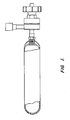
- Two identical MgF 2 chemical craps were constructed using "15" cylinder bodies (see Figure 1 ). Both ends were drilled and a 10 micron filter (see Figure 2 ) was silver soldered into the outlet of the traps. A cajon fitting was silver soldered to the inlet, which allowed access to the trap interior to facilitate trapping material changeouts. The 10 micron filter kept trapping material from contaminating the UF 6 .
- the traps were pressure checked at 1380 kPa gauge (200 psig), leak checked and passivated with fluorine.
- the traps were wrapped with a heat tape and connected to a Variac to control temperature at -100°C.
- the control test is a preliminary filter test in which no MgF 2 trapping media is used. The test is used to determine the amounts of 99 Tc which can be removed on a 10 micron filter in the absence of any trapping media. The test was conducted on traps 1 and 2 with the feed cylinder heel. The traps were washed and the liquid was sent for 99 Tc analysis.
- the 10 micron filters were not effective in trapping 99 Tc from liquid UF 6 .
- the average percent of 99 Tc removal from the liquid UF 6 was about 10 percent with equal amounts of 99 Tc found in the filters and the feed cylinders. This indicated no selective removal of 99 Tc by the filter in the empty trap.
- This example illustrates the effectiveness of a MgF 2 trapping agent in removing 99 Tc from liquid uranium hexafluoride.
- the chemical traps were cleaned and filled with 0.64 cm (1/4") MgF 2 pellets that were manufactured at the Portsmouth Gaseous Diffusion Plant in Piketon, Ohio.
- the filters were evacuated to a vacuum with heat applied, then treated with fluorine several times to remove excess water.
- the inlet UF 6 pressure was throttled at 206 kPa (30 psig).
- the average flow rate of the liquid UF 6 was estimated to be 9.40 x 10 -7 m 3 /s (3.32 x 10 -5 ft 3 /sec) and the residence time was 150 seconds.
- the traps again behaved differently with resultant Tc removal very similar to the results of Test Number 1.
- the trap material was removed and the interior of the trap inspected by a video probe to verify that there was no difference in the trap construction.
- the inequality in Tc removal efficiency may be the result of the 0.64 cm (1/4") pellets allowing channelling through the 3.81 cm (1 1/2") diameter trap body.
- a subsequent test was established to determine if a smaller mesh MgF 2 would provide more consistent results.
- This example illustrates the use of 8-12 mesh MgF 2 for the removal of 99 Tc from liquid UF 6 .
- the increased surface area and bed density of the small mesh MgF 2 produced consistent 99 Tc trapping efficiency of greater than 90 percent.
- the flow rates of the liquid UF 6 through the traps was estimated at 8.8x 10 -7 m 3 /s (3.1 x 10 -5 ft 3 /sec) and did not seem to be affected by the smaller mesh size of the MgF 2 .
- This example illustrates the trapping consistency of the system in Example 3, through several cylinders of UF 6 .
- This example illustrates the removal of 99 Tc from four cylinders of UF 6 containing different concentrations of the contaminant.
- Test Number 5 consisted of running four more cylinders of UF 6 through trap #2. The gaskets were changed as a precaution. The trap was evacuated after UF 6 from each cylinder was passed through the trap.
- Trap #2 removed 96% of the 99 Tc from the four cylinders of UF 6 .
- the flow rate of the liquid UF 6 was estimated at 9.57 x 10 -7 m 3 /s (3.38 x 10 -5 ft 3 /sec) and the residence time was 146 seconds.
- the trapping efficiency discrepancies seen in earlier tests were probably a result of the wet-air inleakage experienced when the filter cooled and the aluminum gasket loosened. As a precaution the gaskets were changed and the trap was immediately evacuated and buffered with nitrogen for the remaining tests.
- This example illustrates the efficiency of the present method using twelve cylinders of contaminated UF 6 .
- the 12 test cylinders used in this test had ⁇ 99% of the 99 Tc removed. The results were consistent at the 98-99% removal efficiency for the total 16,659 grams of UF 6 .
- the flow rate of the liquid UF 6 was estimated to be 1.17 x 10 -6 m 3 /s (4.13 x 10 -5 ft 3 /sec) and the residence time was 120 seconds..
Landscapes
- Physics & Mathematics (AREA)
- Engineering & Computer Science (AREA)
- General Engineering & Computer Science (AREA)
- High Energy & Nuclear Physics (AREA)
- Chemical & Material Sciences (AREA)
- Organic Chemistry (AREA)
- Life Sciences & Earth Sciences (AREA)
- General Life Sciences & Earth Sciences (AREA)
- Geology (AREA)
- Inorganic Chemistry (AREA)
- Inorganic Compounds Of Heavy Metals (AREA)
Abstract
Description
- This invention was made with Government support under Contract No. USEC-96-C-0001, awarded to the United States Enrichment Corporation. The Government has certain rights in this invention.
- The present invention relates to methods of purifying uranium hexafluoride by removing technetium-99 impurities.
- Technetium-99 (99Tc) is a contaminant that is typically present in an enriched UF6 product in low concentrations. This contaminant originates from the fission of 235uranium and is contained in reactor return uranium. Process equipment surfaces in gaseous diffusion plants which process UF6 hold the 99Tc as one or more volatile compounds which are slowly released over time. As a result, the enriched UF6 product which is withdrawn from diffusion plants invariably contains low concentrations of 99Tc, due to a slow leaching from equipment surfaces. The concentrations of the 99Tc impurity, although low, may easily exceed product specification limits, making the uranium hexafluoride product unacceptable to fuel fabricators. Presently, the specification limit for 99Tc in UF6 product is only 0.2 µg/g 23SU or, assuming 5% 235U enrichment, 0.010 µg 99Tc/g U (0.010 ppm, U basis).
- Methods for the removal of 99Tc from UF6 have typically involved gas phase operation (contacting gaseous UF6 with a metal fluoride, typically magnesium fluoride adsorbent). These methods are not effective at the low 99Tc concentrations which impact customer acceptance. For example, the lowest concentrations amenable to gas phase removal are above 0.1 µg 99Tc/g U. Additionally, sufficient throughput must be maintained to provide adequate quantities of the purified UF6. The throughput for UF6 processing which can be obtained with gas phase operations is only about 100-500 lbs/ft2/hour- If the gas velocity is increased to increase UF6 processing rates, 99Tc removal efficiency decreases sharply. Conversely, if gas velocity is decreased to maintain high 99Tc removal, processing rates suffer. In short, existing methods (gaseous UF6 with MgF2 adsorbent) are insufficient to combine both high removal efficiency of 99Tc for direct control at concentrations applicable to market acceptance, and high UP6 processing rates to produce an economic process without burdensome equipment size.
-
US 3,165,376 discloses a process for the separation and recovery of technetium and nepturium fluorides from reprocessed UF6. - What is needed in the art are new methods of removing 99Tc from uranium hexafluoride which overcome the problems associated with existing methods. The present invention provides such processes.
- The present invention provides processes according to claim 1 for the removal of technetium from contaminated uranium hexafluoride containing technetium, typically technetium-99 which is present in several chemical forms or compounds. Some common volatile forms are pertechnetyl fluoride (TcO3F), technetium hexafluoride (TcF6) and technetium oxytetrafluoride (TcOF4). Less volatile forms of technetium include TCO2 and TcF4 or TcF5. Volatility is a relative property and depends upon the temperature of the process. It is generally the 99Tc compounds which are volatile at UF6 handling temperatures that are present in the UF6 product.
- The processes of the present invention involve:
- a) contacting contaminated uranium hexafluoride in liquid form with a solid metal fluoride, typically magnesium fluoride (MgF2), for a period of time sufficient for the technetium to become adsorbed onto the metal fluoride solid thereby producing a purified uranium hexafluoride liquid wherein the rate of UF6 processing is at least 2440 kg/m2/hour (500 lbs/ft2/hour) ; and
- b) removing the purified uranium hexafluoride liquid from the solid metal fluoride, typically magnesium fluoride solid, having adsorbed technetium.
-
-
Figure 1 illustrates a UF6 cylinder "1S" which is used in the Examples. -
Figure 2 shows a liquid UF6 filtering apparatus containing 8-12 mesh MgF2 as an adsorbent and a 10 micron filter. -
Figure 3 illustrates a vacuum manifold system for filtering liquid UF6 and trapping the purified UF6 in a cooled collection vessel. - This invention disclosure describes a process modification which leads to unexpectedly large improvement in the removal of 99Tc from UF6. The process reduces 99Tc in UF6 to below product specification levels for UF6 and further provides high UF6 throughputs. The methods described herein can be applied to control the removal of 99Tc at UF6 product withdrawal stations and/or UF6 liquid transfer facilities on a scale that is attractive for installation at uranium enrichment plants.
- As noted in the Background, existing technology employs magnesium fluoride (MgF2) in the form of pellets which are placed in a reactor. Uranium hexafluoride is passed through the reactor in the gas phase at atmospheric pressures or less. Gas chase operation in itself is inherently limiting in UF6 throughputs or processing rates. Furthermore, this mode of operation fails to perform efficiently as 99Tc concentrations decrease. The lower concentration limit for useful removal and/or control of 99Tc varies with gas velocity and is estimated to be above 0.1 µg/g U and probably much higher. (A typical result in gas phase operation at 13.8 kPa (2 psia) is 2.2 µg/g being reduced by 59% to 0.9 µg/g). It is not possible to obtain UF6 processing rates above about 2440 kg/m2/hour (500 lbs/ft2/hour) at atmospheric pressure or below and still achieve acceptable reduction at concentration below 0.1 µg/g U.
- The present invention is based on the surprising discovery that when liquid UF6 (rather than gaseous UF6) is passed through a trap containing solid MgF2, a remarkable boost in 99Tc removal efficiency is realized at low 99Tc concentrations. As one example, at an initial concentration 0.018 µg/g U, 99Tc is reduced to 0.0008 µg/g U. In other demonstration tests, reductions to below the detection limit (0.0004 µg/g U) are readily obtained. These high efficiencies were not expected considering the state of the art for MgF2 trapping technology. Furthermore, UF6 processing rates are well over 14650 kg/m2/hour (3000 lbs/ft2 /hour). Rates as high as 22460 kg/m2/hour(4600 lbs/fts2/hour) have been successfully demonstrated with no apparent decrease in efficiency. These rates have considerable economic impact as it is now feasible to install a reasonably sized 99Tc removal apparatus at any existing product withdrawal station or UF6 liquid transfer facility without significantly interfering with present operations. Accordingly, direct control of 99Tc in UF6 product is possible and results in further cost savings due to greater flexibility of diffusion operations. The highly purified UF6 product which is obtained using the methods herein, further assures customer acceptance of the UF6 product.
- In view of the above surprising discovery, the present invention provides a process for removal of technetium (99Tc), from contaminated enriched uranium hexafluoride which is withdrawn from a diffusion plant containing the technetium. This process comprises:
- (a) contacting the contaminated uranium hexafluoride in liquid form with a metal fluoride in solid form for a period of time sufficient for the technetium to become adsorbed onto the metal fluoride thereby producing a purified uranium hexafluoride liquid, wherein the rate of UF6 processing is at least 2440 kg/m2/hour (500 lbs/ft2/hour); and
- b) removing the purified uranium hexafluoride liquid from the aolid metal fluoride having adsorbed technetium.
- The present invention utilizes UF6 in liquid form to achieve the significant results provided in the Examples below. Uranium hexafluoride is a volatile white crystalline solid which melts at about 64-65ºC, but which sublimes at about 56-57ºC under pressure of about 101 kPa (1 atmosphere). Accordingly, liquified uranium hexafluoride can be obtained under pressure of about 152 kPa (1.5 atmospheres) and at working temperatures (typically provided in cylinders). Uranium hexafluoride also reacts vigorously with water and care should be taken to remove air and moisture from the trapping system.
- Metal fluorides which are suitable for the removal of technetium from UF6 are generally high melting ionic solids with very low solubility in UF6 . A particularly preferred metal fluoride is magnesium fluoride (MgF2) which is recognized for its technetium removal properties. However, other metal fluorides can also be used, such as AlF3, transition metal fluorides such as NiF2 and related high melting fluorides which are solids at temperatures at which UF6 begins to melt to a liquid. In other embodiments, the metal fluoride used in the invention can be a combination of different metal fluorides (e.g.,. a combination of MgF2 and AlF3).
- The method of contacting the contaminated uranium hexafluoride with a metal fluoride typically involves placing a metal fluoride chemical trap in the UF6 flow line extending from the source of UF6 to a suitable receptacle for purified UF6.
Figures 1-3 provide illustrations of the types of apparatus which can be used in the present invention. One of skill in the art will understand that other apparatuses could also be used to provide the necessary contact between liquid UF6 and the metal fluoride. By allowing the contaminated uranium hexafluoride to pass through, for example, a MgF2 chemical trap, contact is made between the MgF2 and the contaminated UF6, and technetium impurities are adsorbed onto the MgF2. Particular flow rates and contact times (between liquid UF6 and MgF2) will be dependent on the system requirements and capabilities. The examples below provide an indication of flow rates and contact times (or residence times) for a system comprising a "2S" or "1S" feed cylinder of UF6, a MgF2 chemical trap constructed from a "1S" cylinder body, and an attached "2S" cold trap. For this system, a flow rate of about 2.8 x 10⁻⁷ m3/s (1.0 x 10⁻⁵ ft3/sec) to about 9.9 x 10⁻⁷ m3/s (3.5 x 10⁻⁵ ft3/sec) is useful. These flow rates result in chemical trap residence (or contact) times of about 350 seconds to about 100 seconds. Other filters and chemical traps which operate on this same premise, including those versions which are of a larger or smaller scale and of greater or lesser trap voidage, will be known to those of skill in the art. - The amount and physical form (specific surface area and pellet size) of the metal fluoride used in the chemical traps will be dependent on a number of factors including the amount of UF6 to be purified, the size of the trap and the flow rate required. In one group of embodiments, the metal fluoride is MgF2 which is in the form of pellets, preferably about 0.32 cm (1/8 inch) to about 0.95 cm (3/8) inch pellets, more preferably about 0.64 cm (1/4 inch) pellets. In other embodiments, the magnesium fluoride is in the form of 6-15 mesh, preferably 8-12 mesh. The amount of magnesium fluoride used will depend on the level of contamination of UF6 with 99Tc. Typically, magnesium fluoride will adsorb up to about 0.03 g 99Tc per g MgF2. Periodic monitoring of the chemical trap contents will determine whether the chemical trapping agent, MgF2, is in need of replacement.
- Following contacting the contaminated UF6 with the metal fluoride chemical trap, the resultant purified liquid UF6 is removed from the trap. Typically, in a flow-through system, the removal occurs as a matter of course as the liquid UF6 (first contaminated, then purified) is pumped or transferred through the system. Accordingly, attached to the effluent port of the chemical trap is a cold trap for containing the purified UF6. The cold trap is typically a cylinder for longer term storage of the purified UF6 which is immersed in a cold temperature bath, for example a liquid nitrogen bath (-196°C). In a flow-through system the direction of liquid flow may be vertically upward or downward. Alternative modes of liquid-solid contact are also useful, including co-current, countercurrent and unicurrent flow of the liquid and solid phases. The unicurrent flow implies one of the phases is fixed, while the other is mobile. Both phases can be temporarily fixed (no flow) and either one of the two phases is then removed at a later time.
- The following examples are offered solely for the purposes of illustration, and are intended neither to limit nor to define the invention.
- A set of tests was designed to test the removal of 99Tc from liquid UF6 utilizing a MgF2 chemical trap. The tests consisted of transferring liquid UF6, containing a high concentration of 99Tc through a chemical trap and cold trapping the outlet of the trap. The trap contents were varied and a duplicate trap was operated for comparison. The outlet cold traps were subsampled and analyzed for 99Tc and the results evaluated for 99Tc removal efficiencies.
- Two identical MgF2 chemical craps were constructed using "15" cylinder bodies (see
Figure 1 ). Both ends were drilled and a 10 micron filter (seeFigure 2 ) was silver soldered into the outlet of the traps. A cajon fitting was silver soldered to the inlet, which allowed access to the trap interior to facilitate trapping material changeouts. The 10 micron filter kept trapping material from contaminating the UF6. The traps were pressure checked at 1380 kPa gauge (200 psig), leak checked and passivated with fluorine. The traps were wrapped with a heat tape and connected to a Variac to control temperature at -100°C. - Testing was conducted using a vacuum manifold system typically used for liquid UF6 subsampling. The trap was connected to the cajon fitting used for subsampling UF6 cylinders. Tubing extended from the outlet end of the trap to a "2S" container immersed in a liquid nitrogen bath. The liquid UF6 was supplied in "2S" containers. The following steps were used in each test conducted.
- 1. Liquified "2S" feed cylinder.
- 2. Attached cold trap "2S" to manifold
- 3. Attached liquified "2S" feed cylinder to manifold
- 4. pressure and leak checked apparatus
- 5. Applied liquid nitrogen to cold trap
- 6. initiated liquid UF6 flow through filter
- 7. Maintained established pressure limits
- 8. Recorded transfer time and pressures
- 9. subsampled filtered UP6
- 10. Analyzed filtered (purified) UF6 for 99Tc.
- The control test is a preliminary filter test in which no MgF2 trapping media is used. The test is used to determine the amounts of 99Tc which can be removed on a 10 micron filter in the absence of any trapping media.
The test was conducted on traps 1 and 2 with the feed cylinder heel. The traps were washed and the liquid was sent for 99Tc analysis. -
Trap No. Tc Inlet* Concentrations Tc Outlet* Concentrations % Tc Removal Trap #1 0.488 0.429 12.1 Trap #2 0.560 0.510 8-9 * µg Tc/g 235U Wash Solutions Trap No. Feet "2S" Wash Filter* Wash Trap #1 0.966 1.266 Trap #2 1.56 0.741 * µg Tc Total - As can be seen from the above data, the 10 micron filters were not effective in trapping 99Tc from liquid UF6. The average percent of 99Tc removal from the liquid UF6 was about 10 percent with equal amounts of 99Tc found in the filters and the feed cylinders. This indicated no selective removal of 99Tc by the filter in the empty trap.
- This example illustrates the effectiveness of a MgF2 trapping agent in removing 99Tc from liquid uranium hexafluoride.
- The chemical traps were cleaned and filled with 0.64 cm (1/4") MgF2 pellets that were manufactured at the Portsmouth Gaseous Diffusion Plant in Piketon, Ohio. The filters were evacuated to a vacuum with heat applied, then treated with fluorine several times to remove excess water.
- The inlet UF6 pressure was throttled at 206 kPa (30 psig).
-
MgF2 FILTER TEST #1 Trap no. Transfer Wt. Gms. Tc Inlet* Concentrations Tc Outlet* Concentrations µg Tc Removed Tc% Removal Trap #1 1494 0.429 0.0286 20.1 93.5 Trap #2 1729 0.51 0.219 14.2 57.5 * Ug Tc/g 235U - As the above data indicates, the traps removed 99Tc in much greater amounts than the controls. The amounts removed in Traps #1 and #2 differed significantly, however. The inequality may have been due to the difference in weight of MgF2 in the traps.
- This example illustrates the impact of unequal eights of MgF2 on the ability of the traps to sequester 99Tc. In view of the results in Example 1, this test utilized equal amounts of MgF2 in the two traps.
- Two traps were loaded equally with 40 grams of 0.64 cm (1/4") MgF2 pellets, then heated, evacuated, and fluorinated as described above. A pressure gauge was added to the outlet line of the traps. The pressure differentials were recorded to indicate any pressure drop occurring through the MgF2 trap. The flow rate of the liquid UF6 was estimated to be 4.59 x 10⁻⁷ m3/s (1.62 x 10⁻⁵ ft3/sec) and the residence time was about 306 seconds.
-
MgF2 FILTER TEST #2 Trap no. Transfer Wt. Gms. Tc Inlet* Concentrations Tc Outlet* Concentrations µg Tc Removed Tc % Removal Trap #1 2036 0.437 0.078 20.5 82.3 Trap #2 1741 0.440 0.198 11.7 55.2 * µg Tc/g 235U - The average flow rate of the liquid UF6 was estimated to be 9.40 x 10⁻⁷ m3/s (3.32 x 10⁻⁵ ft3/sec) and the residence time was 150 seconds. The traps again behaved differently with resultant Tc removal very similar to the results of Test Number 1. The trap material was removed and the interior of the trap inspected by a video probe to verify that there was no difference in the trap construction. The inequality in Tc removal efficiency may be the result of the 0.64 cm (1/4") pellets allowing channelling through the 3.81 cm (1 1/2") diameter trap body. A subsequent test was established to determine if a smaller mesh MgF2 would provide more consistent results.
- This example illustrates the use of 8-12 mesh MgF2 for the removal of 99Tc from liquid UF6.
- In this test the two traps were each loaded with 106grams of 8-12 mesh MgF2. The traps were evacuated under heat and fluorinated as described above.
-
MgF2 FILTER TEST #3 Smaller Pellets 8 - 12 Mesh Trap no. Transfer Wt. Gms. Tc Inlet* Concentrations Tc Outlet* Concentrations µg Tc Removed Tc % Removal Trap #1 1816 0.379 0.286 18.4 92.6 Trap #2 1648 0.3906 0.0174 19.6 95.6 * µg Tc/g 238U - The increased surface area and bed density of the small mesh MgF2 produced consistent 99Tc trapping efficiency of greater than 90 percent. The flow rates of the liquid UF6 through the traps was estimated at 8.8x 10⁻⁷ m3/s (3.1 x 10⁻⁵ ft3/sec) and did not seem to be affected by the smaller mesh size of the MgF2.
- This example illustrates the trapping consistency of the system in Example 3, through several cylinders of UF6.
- Testing was continued by running several "2S" containers of UF6 through trap #2 to determine consistency of 99Tc removal efficiency. It must be noted that the trap experienced a wet-air inleakage following cooldown after Test Number 3 (above). The gasket was changed and Test Number 4 was conducted.
-
MgF2 FILTER TEST #4 Cylinder Number Transfer W1. Gms. Tc Inlet* Concentrations Tc Outlet* Concentrations µg Tc Removed Tc % Removal 2 1690 0.219 0.039 8.61 82.5 3 1687 0.188 0.029 8.1 85.5 4 1607 0.0174 0.035 -0.85 No Removal * µg Tc/g 235U - More than 80 percent of the 99Tc was removed in two of the test cylinders. However, this amount is 10% less than the results seen in Test Number 3. The flow rate of the liquid UF6, was estimated at 1.03 x 10⁻⁶ m3/s (3.65 x 10⁻⁵ ft3/sec) and the residence time was 136 seconds. The wet-air inleakage may have affected the results. More UF6 may have hydrolyzed on water sites of the MgF2 pellets taking up sites for 99Tc trapping to occur. Cylinder 4 was tested to see how the MgF2 would remove even low level 99Tc from liquid UF6. The 99Tc outlet concentrations were the same as previous tests which was apparently due to release of material from previous tests. However, the results could indicate sampling and detection errors at such low levels of technetium.
- This example illustrates the removal of 99Tc from four cylinders of UF6 containing different concentrations of the contaminant.
- Test Number 5 consisted of running four more cylinders of UF6 through trap #2. The gaskets were changed as a precaution. The trap was evacuated after UF6 from each cylinder was passed through the trap.
- Four cylinders containing several different concentrations of 99Tc were used for this test.
-
FILTER 2 Cylinder Number Transfer Wt. Gms. Tc Inlet* Concentrations Tc Outlet* Concentrations µg To Removed Tc % Removal 6 1568 0.465 <0.02 9.6 95.8 6 1469 0.408 0.016 9.7 96.1 7 1909 0.19 <0.008 11.8 95.8 8 301 1.40 0.021 5.7 98.6 * µg Tc/g 235U - Trap #2 removed 96% of the 99Tc from the four cylinders of UF6. The flow rate of the liquid UF6 was estimated at 9.57 x 10⁻⁷ m3/s (3.38 x 10⁻⁵ ft3/sec) and the residence time was 146 seconds. The trapping efficiency discrepancies seen in earlier tests were probably a result of the wet-air inleakage experienced when the filter cooled and the aluminum gasket loosened. As a precaution the gaskets were changed and the trap was immediately evacuated and buffered with nitrogen for the remaining tests.
- This example illustrates the efficiency of the present method using twelve cylinders of contaminated UF6.
- Twelve "2S" cylinders containing 1.303 µg Tc/g 235U were trapped consecutively in this test. The trap was evacuated after each cylinder was transferred. Trap #2 was used with the same trapping media as used in the previous tests.
-
Cylinder Number Transfer Wt. grams Tc Inlet* Concentrations Tc Outlet* Concentrations µg 99Tc Removed Percent Removal 9 1213 1.303 0.011 47.2 99.2 10 1449 1.303 0.011 56.3 99.2 11 1187 1.303 0.015 46.0 98.9 12 1248 1.303 0.013 48.4 99.0 13 1132 1.303 0.018 43.8 98.6 14 2181 1.303 0.009 85.0 99.3 15 1195 1.303 0.020 48.1 98.5 16 1352 1.303 0.009 52.7 99.3 17 1199 1.303 0.009 46.7 99.3 18 1160 1.303 0.025 44.6 98.1 19 1799 1.303 0.031 68.8 97.6 20 1542 1.303 0.016 59.7 98.8 16,657 645.3 - The 12 test cylinders used in this test had ≈99% of the 99Tc removed. The results were consistent at the 98-99% removal efficiency for the total 16,659 grams of UF6. The flow rate of the liquid UF6 was estimated to be 1.17 x 10⁻⁶ m3/s (4.13 x 10⁻⁵ ft3/sec) and the residence time was 120 seconds..
- The total 99Tc contained in chemical trap #2, after a total of 20 "25" cylinders were filtered, was theoretically 718 µg Tc. The high percentage removal of Tc indicates that saturation was not approached. These results further indicate that UF6 contact with MgF2 is more important than flow rates and residence time within the boundaries of our tests. This series of tests has demonstrated that with the 8-12 mesh MgF2 and a trap bed of 106 grams in the 7 x 3.81 cm (1 1/2 inch) chambers in excess of 28 Kg of UF6, were successfully stripped of 99Tc.
- Although the foregoing invention has been described in some detail by way of illustration and example for purposes of clarity of understanding, it will be obvious that certain changes and modifications may be practiced within the scope of the appended claims.
Claims (11)
- A process for the removal of technetium from contaminated enriched uranium hexafluoride which is withdrawn from a diffusion plant containing said technetium, said process comprising:(a) contacting said contaminated uranium hexafluoride in liquid form with metal fluoride in solid form for a period of time sufficient for said technetium to become adsorbed onto said metal fluoride thereby producing a purified uranium hexafluoride liquid, wherein the rate of UF6 processing is at least 2440 kg/m2/hour (500 lbs/ft2/hour); and(b) removing said purified uranium hexafluoride liquid from said metal fluoride having adsorbed technetium.
- A process in accordance with claim 1, wherein said technetium is technetium-99.
- A process in accordance with claim 1, wherein said metal fluoride is magnesium fluoride in the form of pellets.
- A process in accordance with claim 1, wherein said metal fluoride is magnesium fluoride in the form of 0.32 cm to 0.95 cm (1/8" to 3/8") pellets.
- A process in accordance with claim 1, wherein said metal fluoride is magnesium fluoride in the form of 8-12 mesh pellets.
- A process in accordance with claim 1, wherein said metal fluoride is present in a trap and is treated with fluorine prior to said contacting step (a).
- A process in accordance with claim 1, wherein the rate of UF6 processing is at least 14650 kg/m2/hour (3000 lbs/ft2/hour).
- A process in accordance with claim 1, wherein the rate of UF6 processing is at least 22460 kg/m2/hour (4600 lbs/ft2/hour).
- A process in accordance with claim 1, wherein said purified uranium hexafluoride liquid contains less than about 0.1 µg technetium/g uranium.
- A process in accordance with claim 1, wherein said purified uranium hexafluoride liquid contains less than about 0.01 µg technetium/g uranium.
- A process in accordance with claim 1, wherein said purified uranium hexafluoride liquid contains less than about 0.001 µg technetium/g uranium.
Applications Claiming Priority (3)
| Application Number | Priority Date | Filing Date | Title |
|---|---|---|---|
| US08/860,000 US5826163A (en) | 1997-05-21 | 1997-05-21 | Removal of technetium impurities from uranium hexafluoride |
| US860000 | 1997-05-21 | ||
| PCT/US1998/007163 WO1998052872A1 (en) | 1997-05-21 | 1998-04-09 | Removal of technetium impurities from uranium hexafluoride |
Publications (3)
| Publication Number | Publication Date |
|---|---|
| EP0984903A1 EP0984903A1 (en) | 2000-03-15 |
| EP0984903A4 EP0984903A4 (en) | 2005-02-16 |
| EP0984903B1 true EP0984903B1 (en) | 2012-02-01 |
Family
ID=25332272
Family Applications (1)
| Application Number | Title | Priority Date | Filing Date |
|---|---|---|---|
| EP98915443A Expired - Lifetime EP0984903B1 (en) | 1997-05-21 | 1998-04-09 | Removal of technetium impurities from uranium hexafluoride |
Country Status (5)
| Country | Link |
|---|---|
| US (1) | US5826163A (en) |
| EP (1) | EP0984903B1 (en) |
| JP (1) | JP4183759B2 (en) |
| AU (1) | AU6962498A (en) |
| WO (1) | WO1998052872A1 (en) |
Families Citing this family (12)
| Publication number | Priority date | Publication date | Assignee | Title |
|---|---|---|---|---|
| AU2007363064B2 (en) | 2007-12-26 | 2014-02-13 | Thorium Power Inc. | Nuclear reactor (variants), fuel assembly consisting of driver-breeding modules for a nuclear reactor (variants) and a fuel cell for a fuel assembly |
| US8116423B2 (en) | 2007-12-26 | 2012-02-14 | Thorium Power, Inc. | Nuclear reactor (alternatives), fuel assembly of seed-blanket subassemblies for nuclear reactor (alternatives), and fuel element for fuel assembly |
| JP5755568B2 (en) | 2008-12-25 | 2015-07-29 | トリウム・パワー、インクThorium Power,Inc. | Light water reactor nuclear fuel assembly and light water reactor |
| US10170207B2 (en) | 2013-05-10 | 2019-01-01 | Thorium Power, Inc. | Fuel assembly |
| WO2011143172A1 (en) | 2010-05-11 | 2011-11-17 | Thorium Power, Inc. | Fuel assembly with metal fuel alloy kernel and method of manufacturing thereof |
| US10192644B2 (en) | 2010-05-11 | 2019-01-29 | Lightbridge Corporation | Fuel assembly |
| FR2976281B1 (en) | 2011-06-09 | 2014-06-13 | Comurhex Soc Pour La Conversion De L Uranium En Metal Et Hexafluorure | USE OF KMGF3 COMPOUND FOR PIEGING METALS PRESENT IN THE FORM OF FLUORIDES AND / OR OXYFLUORIDES IN A GAS OR LIQUID PHASE |
| US9108867B2 (en) | 2012-08-22 | 2015-08-18 | Areva Inc. | Immobilization of Technetium by Electroless Plating |
| US9443627B1 (en) * | 2013-05-08 | 2016-09-13 | Sandia Corporation | Apatite sequestration of technetium |
| US9440217B1 (en) * | 2013-05-08 | 2016-09-13 | Sandia Corporation | Apatite sequestration of selenium |
| EP2899725B1 (en) * | 2014-01-27 | 2018-04-25 | Urenco Limited | Controlling the temperature of uranium material in a uranium enrichment facility |
| CN115608023A (en) * | 2022-10-31 | 2023-01-17 | 中核四0四有限公司 | A device for filtering and purifying liquid-phase uranium hexafluoride |
Family Cites Families (5)
| Publication number | Priority date | Publication date | Assignee | Title |
|---|---|---|---|---|
| DE1250801B (en) | 1962-04-02 | 1967-09-28 | United States Atomic Energy Commission, Washington, D.C. (V. St. A.) | Process for the separation of volatile fluoride impurities from uranium hexafluoride |
| FR2091897B1 (en) * | 1970-04-08 | 1973-08-10 | Commissariat Energie Atomique | |
| CA978669A (en) * | 1971-06-03 | 1975-11-25 | Moser Manufacturing Co. Ltd. | Cushion inner spring and its method of manufacture |
| US3848048A (en) * | 1973-07-12 | 1974-11-12 | Atomic Energy Commission | Recovery of fission-produced technetium,palladium,rhodium and ruthenium |
| US5613186A (en) * | 1996-01-11 | 1997-03-18 | General Electric Company | Method for monitoring the ADU process for technetium |
-
1997
- 1997-05-21 US US08/860,000 patent/US5826163A/en not_active Expired - Lifetime
-
1998
- 1998-04-09 WO PCT/US1998/007163 patent/WO1998052872A1/en not_active Ceased
- 1998-04-09 JP JP55035398A patent/JP4183759B2/en not_active Expired - Lifetime
- 1998-04-09 EP EP98915443A patent/EP0984903B1/en not_active Expired - Lifetime
- 1998-04-09 AU AU69624/98A patent/AU6962498A/en not_active Abandoned
Also Published As
| Publication number | Publication date |
|---|---|
| EP0984903A1 (en) | 2000-03-15 |
| JP4183759B2 (en) | 2008-11-19 |
| US5826163A (en) | 1998-10-20 |
| JP2001525785A (en) | 2001-12-11 |
| WO1998052872A1 (en) | 1998-11-26 |
| AU6962498A (en) | 1998-12-11 |
| EP0984903A4 (en) | 2005-02-16 |
Similar Documents
| Publication | Publication Date | Title |
|---|---|---|
| US5826163A (en) | Removal of technetium impurities from uranium hexafluoride | |
| DE2426764C2 (en) | Process for separating krypton from a radioactive exhaust gas mixture and gas separation system for carrying out the process | |
| EP0366078B1 (en) | Method for Purifying nitrogen trifluoride gas | |
| US4863493A (en) | High purity acetylene gas | |
| US5032218A (en) | Sulfuric acid reprocessor | |
| US8795411B2 (en) | Method for recovering high-value components from waste gas streams | |
| US7396381B2 (en) | Storage and delivery systems for gases held in liquid medium | |
| DE60114348T2 (en) | Process for the purification of gases | |
| WO2002045846A1 (en) | Method and materials for purifying hydride gases, inert gases, and non-reactive gases | |
| US7514588B2 (en) | Purification of organic solvents | |
| EP3569573A1 (en) | Method for producing polycrystalline silicon | |
| CA1318108C (en) | Process for purifying nitrogen trifluoride gas | |
| JPS59107910A (en) | Method for purifying gaseous argon | |
| JP5542315B2 (en) | Fluid storage and transport system consisting of high capacity physical adsorbent | |
| US4555318A (en) | Removal of fluoride impurities from UF6 gas | |
| JPH11506411A (en) | On-site ammonia purification for electronic component manufacturing. | |
| DE2621598A1 (en) | METHOD OF TREATMENT OF RADIOACTIVE EMISSIONS | |
| JPS6354402B2 (en) | ||
| US2863718A (en) | Plutonium concentration and decontamination method | |
| US4347214A (en) | Failed fuel detection and location apparatus | |
| JPH05255154A (en) | Isopropyl alcohol | |
| USH808H (en) | Removal of I, Rn, Xe and Kr from off gas streams using PTFE membranes | |
| US20040038803A1 (en) | Adsorbent for removing water vapor during corrosive gas purification and method for preparing the adsorbent | |
| JPH07122058B2 (en) | Solvent consisting of high quality methylene chloride | |
| JP3472658B2 (en) | Regeneration method of anion exchange resin |
Legal Events
| Date | Code | Title | Description |
|---|---|---|---|
| PUAI | Public reference made under article 153(3) epc to a published international application that has entered the european phase |
Free format text: ORIGINAL CODE: 0009012 |
|
| 17P | Request for examination filed |
Effective date: 19991209 |
|
| AK | Designated contracting states |
Kind code of ref document: A1 Designated state(s): DE FR GB |
|
| A4 | Supplementary search report drawn up and despatched |
Effective date: 20050104 |
|
| RIC1 | Information provided on ipc code assigned before grant |
Ipc: 7G 21F 9/12 B Ipc: 7G 21F 9/02 B Ipc: 7G 21F 9/00 B Ipc: 7C 01G 43/06 A |
|
| GRAP | Despatch of communication of intention to grant a patent |
Free format text: ORIGINAL CODE: EPIDOSNIGR1 |
|
| GRAS | Grant fee paid |
Free format text: ORIGINAL CODE: EPIDOSNIGR3 |
|
| GRAA | (expected) grant |
Free format text: ORIGINAL CODE: 0009210 |
|
| AK | Designated contracting states |
Kind code of ref document: B1 Designated state(s): DE FR GB |
|
| REG | Reference to a national code |
Ref country code: GB Ref legal event code: FG4D |
|
| REG | Reference to a national code |
Ref country code: DE Ref legal event code: R096 Ref document number: 69842583 Country of ref document: DE Effective date: 20120329 |
|
| PLBE | No opposition filed within time limit |
Free format text: ORIGINAL CODE: 0009261 |
|
| STAA | Information on the status of an ep patent application or granted ep patent |
Free format text: STATUS: NO OPPOSITION FILED WITHIN TIME LIMIT |
|
| 26N | No opposition filed |
Effective date: 20121105 |
|
| REG | Reference to a national code |
Ref country code: DE Ref legal event code: R097 Ref document number: 69842583 Country of ref document: DE Effective date: 20121105 |
|
| REG | Reference to a national code |
Ref country code: FR Ref legal event code: PLFP Year of fee payment: 19 |
|
| REG | Reference to a national code |
Ref country code: FR Ref legal event code: PLFP Year of fee payment: 20 |
|
| PGFP | Annual fee paid to national office [announced via postgrant information from national office to epo] |
Ref country code: FR Payment date: 20170313 Year of fee payment: 20 |
|
| PGFP | Annual fee paid to national office [announced via postgrant information from national office to epo] |
Ref country code: DE Payment date: 20170404 Year of fee payment: 20 Ref country code: GB Payment date: 20170405 Year of fee payment: 20 |
|
| REG | Reference to a national code |
Ref country code: DE Ref legal event code: R071 Ref document number: 69842583 Country of ref document: DE |
|
| REG | Reference to a national code |
Ref country code: GB Ref legal event code: PE20 Expiry date: 20180408 |
|
| PG25 | Lapsed in a contracting state [announced via postgrant information from national office to epo] |
Ref country code: GB Free format text: LAPSE BECAUSE OF EXPIRATION OF PROTECTION Effective date: 20180408 |