EP0984392B1 - Image processor and image processing method - Google Patents
Image processor and image processing method Download PDFInfo
- Publication number
- EP0984392B1 EP0984392B1 EP98921774A EP98921774A EP0984392B1 EP 0984392 B1 EP0984392 B1 EP 0984392B1 EP 98921774 A EP98921774 A EP 98921774A EP 98921774 A EP98921774 A EP 98921774A EP 0984392 B1 EP0984392 B1 EP 0984392B1
- Authority
- EP
- European Patent Office
- Prior art keywords
- polygons
- constituting elements
- region
- processing
- polygon
- Prior art date
- Legal status (The legal status is an assumption and is not a legal conclusion. Google has not performed a legal analysis and makes no representation as to the accuracy of the status listed.)
- Expired - Lifetime
Links
Images








Classifications
-
- G—PHYSICS
- G06—COMPUTING OR CALCULATING; COUNTING
- G06T—IMAGE DATA PROCESSING OR GENERATION, IN GENERAL
- G06T15/00—Three-dimensional [3D] image rendering
- G06T15/50—Lighting effects
- G06T15/80—Shading
-
- G—PHYSICS
- G06—COMPUTING OR CALCULATING; COUNTING
- G06T—IMAGE DATA PROCESSING OR GENERATION, IN GENERAL
- G06T1/00—General purpose image data processing
-
- G—PHYSICS
- G06—COMPUTING OR CALCULATING; COUNTING
- G06T—IMAGE DATA PROCESSING OR GENERATION, IN GENERAL
- G06T1/00—General purpose image data processing
- G06T1/20—Processor architectures; Processor configuration, e.g. pipelining
Definitions
- the present invention relates to an image processor and an image processing method for computer graphics.
- fragment In the field of computer graphics, to realize a higher capability of image processing, there has been known a method of processing by which a screen is divided into tiny rectangular regions (hereinafter referred to as "fragments") and processing is done fragment by fragment.
- each polygon is divided by frames of fragments and memorized with the fragments containing the polygons known.
- Fig.14 there are fifteen fragments arranged in a matrix of 3x5, on which polygons A, B and C are defined. Concerning the polygon A, it corresponds to eight fragments, as shown in Fig.15.
- These fragments are stored in a buffer memory shown in Fig.16 according to their coordinates ⁇ , ⁇ , ⁇ , etc.
- ⁇ 1 and ⁇ 2 in Fig.15 are stored in the memory area ⁇ of the buffer memory
- ⁇ 1 and ⁇ 2 in Fig.15 are stored in the memory area ⁇ of the buffer memory
- ⁇ 1 and ⁇ 2 in Fig.15 are stored in the memory area ⁇ of the buffer memory. The same is applied to the remaining coordinates.
- fragments covered by a polygon currently concerned are computed and painted.
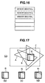
- a fragment ⁇ 1 is first painted toward the polygon A (see Fig.17(b)), painted toward the polygon B (see Fig.17(c)), and finally painted toward the polygon C (see Fig.17(d)).
- Such operation is repeated until the final polygon is processed or the fragment is totally covered. And the forgoing processing is performed for all the fragments.
- a storage of a greater capacity needs to be arranged to memorize information to be produced about polygons which have been divided.
- the storage should be faster in operation, raising the cost for the storage.
- the present invention is intended to resolve the foregoing problems, and aims to enable processing of data of image elements to be performed efficiently and rapidly in computer graphic systems and to obtain higher-quality images at a lower cost than in conventional systems.
- One method to realize such an aim is based on dividing a screen into tiny regions (fragments) for processing, and efficiently retrieving polygons included in regions concerned.
- a system and a method according to the invention can provide images of higher quality at a lower cost than in the conventional systems.
- the invention provides an image processor in which a screen is divided into regions of a predetermined size and processing on polygon data is performed region by region, comprising first rearranging means for providing constituting elements of a plurality of polygons, falling into individual regions on the screen in a direction vertical to a scanning line, with vertical links mutually linking constituting elements of a polygon, and for rearranging links to constituting elements falling into the same region, thus linking these elements; second rearranging means for providing constituting elements of a plurality of polygons, falling into individual regions on the screen in the direction of the scanning line, with horizontal links mutually linking constituting elements of a polygon, and for rearranging links to constituting elements falling into the same region, thus linking these elements; and an image processing means for retrieving and processing constituting elements of diverse polygons falling in a given region, the sequence of constituting elements being given by rearranged links.
- the first rearranging means is operable to perform the rearrangement based on minimum or maximum values of the constituting elements with reference to the vertical direction; and the second rearranging means is operable to perform the rearrangement based on minimum or maximum values of the constituting elements with reference to the horizontal direction, in vertical coordinates of a region to be processed by the first rearranging means.
- the first and second rearranging means determine whether or not, after completion of the processing of a polygon in the image processing means for a said region, the constituting elements for said polygon to be used by the image processing means are included in a region to be image-processed at the next processing, and perform link update processing which removes from the link the constituting elements which are determined to not be included.
- the image processing means as to image processing for each divided region, not only sections polygons to be processed into opaque polygons, polygons with transparent pixels, and semitransparent polygons but also processes in the order of the opaque polygons, polygons with transparent pixels, and semitransparent polygons.
- the invention provides an image processing method by which a screen is divided into regions of a predetermined size, and processing on polygon data is performed region by region,the method comprising the steps of a first rearranging step of providing constituting elements of a plurality of polygons, falling into individual regions on the screen in a direction vertical to a scanning line, with vertical links mutually linking constituting elements of a polygon, and rearranging links to constituting elements falling into the same region, thus linking these elements; a second rearranging step of providing constituting elements of a plurality of polygons, falling into individual regions on the screen in the direction of the scanning line, with horizontal links mutually linking constituting elements of a polygon, and rearranging links to constituting elements falling into the same region, thus linking these elements; and an image processing step of retrieving and processing constituting elements of diverse polygons falling in a given region, the sequence of constituting elements being given by rearranged links.
- the rearrangement in the first rearranging step, is performed based on minimum or maximum values of the constituting elements with reference to the vertical direction, and in the second rearranging step, the rearrangement is performed based on minimum or maximum values of the constituting elements with reference to the horizontal direction, in vertical coordinates of a region to be processed in the first rearranging step.
- link update processing is performed to invalidate an unnecessary region among the regions corresponding to the constituting elements.
- the image processing for each divided region is performed with polygons to be processed sectioned into opaque polygons, polygons with transparent pixels, and semitransparent polygons, and performed in the order of the opaque polygons, polygons with transparent pixels, and semitransparent polygons.
- Fig. 1 is an outlined functional block diagram of an image processor according to the embodiment of the present invention.
- a reference 1 is a CPU (central processing unit), which is used to operate for objects in a virtual space, to obtain operating information, and to perform a variety of controls.
- a reference 2 shows a geometry processor that performs high speed geometric conversion (i.e. calculation in vector quantities), such as coordinate conversion of polygons, clipping, perspective conversion in the three-dimensional computer graphics and/or intensity calculation.
- a reference 2a is a polygon/material/light buffer memory (polygon/material/light buffer RAM), which is used to memorize valid polygon data, material data, and light data for one frame by the geometry processor 2 under operation.
- the polygons are polyhedrons constituting solids in the virtual space.
- the contents of data stored into the buffer memory 2a are as follows:
- a reference 3 is a fill processor that is in charge of hidden-surface elimination processing.
- the fill processor 3 paints polygons existing within a region in order to acquire pixel by pixel each piece of information on a polygon that is placed in the foreground position.
- a reference 4 is a texture processor.
- the texture processor 4 maps textures on each pixel in a region. Texture mapping is processing that, for producing images, maps textures defined differently from the shape of an object onto the surface of the object of which shape is defined.
- a reference 4a is a texture memory (texture RAM), in which texture maps used in the processing of the texture processor 4 are preserved.
- a reference 5 shows a shading processor.
- the shading is a technique that expresses shades or the like on objects composed of polygons in consideration of normal vectors of polygons, locations and colors of a light source, locations of a view point, directions of a line of sight, and others.
- the shading processor 5 calculates intensities of each pixel within a region.
- a reference 5a is a frame buffer into which image data for one screen are stored. Data are read in sequence from the frame buffer 5a, and then converted from digital data to analog signals, before supplied to such displays as a CRT, liquid crystal display, plasma display device, which are not shown in the figure.
- a reference 6 represents a program work/polygon buffer memory (program work/polygon buffer RAM) memorizing commands (such as database of polygons and display lists) to a graphic processor as well as programs to the CPU 1.
- the buffer memory 6 also serves as a work memory for the CPU 1.
- the fill processor 3, texture processor 4 and shading processor 5 are arranged for processing referred to as rendering.
- the rendering starts sequentially from its upper left position of the screen.
- the geometry enables objects to be located in the virtual space coordinates, and perspective-converts them onto a screen.
- pictures are produced by processing data defined on the screen coordinate.
- the rendering is repeated by the number of regions.
- Fig. 2 is a functional block diagram of the geometry processor 2.
- a reference 21 is a data dispatcher that not only reads commands from the buffer memory 6 but also analyzes them, controls a vector engine 22 and a clipping engine 24 based on the analyzed results, and provides a sort engine 27 with processed data.
- a reference 22 shows a vector engine performing vector calculation. Vectors handled by the engine are stored in a vector register 23.
- a reference 23 is a vector register, which preserves vector data which the vector engine 22 calculates.
- a reference 24 is a clipping engine for clipping.
- a reference 25 indicates a Y-sort index (Y-sort INDEX) preserving Y-indices used in Y-sorting executed by a sort engine 27.
- a reference 26 expresses an X-sort index (X-sort INDEX) preserving X-indices used in X-sorting executed by a sort engine 27.
- a reference 27 shows a sort engine that carries out X-sorting and Y-sorting, retrieving from the buffer 6 polygons falling into a fragment concerned.
- the retrieved polygons are not merely stored into the buffer memory 2a but also sent to the fill processor 3 for rendering.
- the sort engine 27 is also in charge of control of both a polygon TAG 28 and a polygon cache 34.
- a reference 28 is a polygon TAG for preserving TAG of the polygon cache 34.
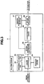
- Fig.3 shows a functional block diagram of the fill processor 3.
- a reference 31 is a cache controller controlling later-described material caches 42, 45, 51b, 52a and 53a and a light cache 51a.
- a reference 32 is a material TAG, which preserves TAGs of later-described material caches 42, 45, 51b, 52a and 53a and a light cache 51a.
- a reference 33 is a light TAG, which is a buffer preserving TAG of a light cache 51a described later.
- a reference 34 represents a polygon cache, serving as a cache memory of polygon data.
- a reference 35 shows an initial parameter calculator used for obtaining an initial value of DDA.
- a reference 36 shows a Z-comparator array, which is responsible for the Z-comparison between polygons for hidden-surface elimination loading as well as processing polygon IDs and an interior division ratio of t0, t1 and t2.
- the Z-comparator array 36 is composed of 64 (8x8) Z-comparators. These comparators operate in parallel, which enables 64 pixels to be processed concurrently.
- One Z-comparator preserves data of a polygon. For example, these data include polygon ID, iz, t0, t1, t2, window, stencil, and shadow.
- a reference 37 is a vertex parameter buffer, which preserves parameters at the vertexes of polygons.
- the buffer has a capability of memorizing data of 64 polygons.
- a reference 38 is an interpolator that calculates parameters of pixels by interpolation on the basis of the results t0, t1, t2 and iz calculated by the Z-buffer array 36 and the contents of the vertex parameter buffer 37.
- Fig.4 is a functional block diagram of the texture processor 4.
- a reference 41 is a density calculator calculating a blend ratio necessary for fog and depth queuing.
- a reference 42 shows a material cache where data regarding depth information are stored.
- a reference 43 indicates a window register to preserve pieces of information concerning windows. Such information is expressed in the form of kz, cz, fog function, fog density, and fog end z, for example.
- a reference 44 is an address generator calculating addresses on a texture map using texture coordinates Tx, Ty and LOD.
- a reference 45 shows a material cache in which data concerning materials are preserved.
- a reference 46 is a TLMMI calculator (TLMMI: Tri Linear MIP Map Interpolation) that performs "Tri Linear MIP Map interpolation" adopted as three-dimensional interpolation.
- TLMMI Tri Linear MIP Map Interpolation
- the "MIP Map” is a technique eliminating anti aliasing, that is, jags of textures in mapping textures. This technique relies upon the following principle. In principle, the color (intensity) of the surface of an object projected onto one pixel should be a mean value over the colors of corresponding mapping regions thereto. If not so, jags become apparent, severely deteriorating the quality of textures. Processing to obtain each mean value leads to enormous quantities of calculation load, with the result that processing takes a longer time or a fast processor is required. The MIP Map is a solution to this situation.
- mapping data of which width is a multiple of two are prepared in advance.
- the sizes of all mapping regions in association with one pixel become values that exist between any two data produced by multiplying them by a multiple of two.
- the colors of the corresponding mapping regions are obtained. For instance, if there are a one-time screen A and a 1/2-time screen B, each pixel of both the screens A and B corresponding to each pixel of a 1/1.5-time screen C is obtained.
- the color of each pixel of the screen C equals a medium color between the pixels of both the screens A and B.
- a reference 47 is a color converter converting colors in 4-bit texel processing.
- a reference 48 shows a color pallet in which color information is preserved in 4-bit texel processing.
- the color pallet 48 is used to store colors for graphic drawing. On the basis of the contents of the color pallet 48, a color available to each pixel is determined.
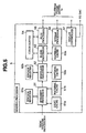
- Fig.5 is a functional block diagram of the shading processor 5.
- a reference 51 is an intensity processor that calculates intensities of polygons on which texture mapping has been completed.
- a reference 51a is a light cache to memorize information on light.
- a reference 51b shows a material cache to memorize information about materials. This information includes Shinies, Material specular, and material emission.
- a reference 51c is a window register to preserve information about windows. Such information is formed from Screen center, Focus, Scene ambient, and others.
- a reference 52 indicates a modulate processor that performs associating polygon colors with texture colors, intensity modulation, and fog processing.
- a reference 52a is a material cache in which information on materials is stored. Such information includes Polygon color and Texture mode.
- a reference 52b is a window register to preserve information on windows. This information includes Fog colors.
- a reference 53 represents a blend processor that performs blending with data stored in a color buffer 54 and writes the result into the color buffer 54.
- the blend processor 53 blends a current pixel color and a pixel color of a frame buffer on the basis of a blend rate register, and then writes the blended result into a frame buffer of a bank represented by a write bank register.
- a reference 53a is a material cache in which information regarding materials is stored. This information includes "blend mode.”
- a reference 54 shows a color buffer having the same size "8x8" as the fragments, which is made up of a double-bank structure.
- a reference 55 is a plot processor that writes data in the color buffer 54 into the frame buffer 5a.
- a reference 56 is a bitmap processor performing bitmap processing.
- a reference 57 represents a display controller, which reads data in the frame buffer 5a, and provides them to a DAC (Digital to Analogue Converter) in order to show them on a not-shown display.
- DAC Digital to Analogue Converter
- polygons are rearranged in both the vertical direction (hereinafter referred to as the Y-direction) and the horizontal direction (hereinafter referred to as the X-direction) to a scanning line, resulting in that polygons included in each fragment can be retrieved.
- this retrieved information makes it possible to process polygons every fragment concerned currently, enabling the processing without the foregoing division of the polygons. Accordingly, processing time is shortened and it is possible to realize the processing using an apparatus of which the memory device is smaller in capacity.
- the polygons are divided into types of opaque polygons, semitransparent polygons, and polygons with transparent pixels, and the semitransparent polygons are processed at the final step, which makes it possible to process the semitransparent polygons.
- Polygon data to be transmitted to the rendering section are rearranged by a minimum Y-coordinate value of the polygons, and written into the buffer (ST1).
- Polygon data agreeing with the Y-coordinate value of a fragment concerned currently are rearranged by a minimum X-coordinate value of a concerned Y-region of polygons (ST2).
- Rendering is performed toward all the opaque polygons whose coordinate agree with X- and Y-coordinates of a currently concerned fragment (ST3).
- Rendering is performed toward all the transparent polygons whose coordinates agree with X- and Y-coordinates of a currently concerned fragment (ST4).
- the steps ST4 and ST5 may be executed in the opposite order. Actually, it may be more practical to execute them in the order of steps ST5 to ST4.
- polygon data are first rearranged by Y, then the rearranged data are rearranged by minimum values of X in a region Y before proceeding to processing of each line.
- the position of a fragment of a polygon, which is to be processed at first is found. Accordingly, it is first found which fragment includes the polygon.
- each polygon undergoes link update processing (later described), by which polygons unnecessary for the fragments to be processed subsequently are removed, so that only necessary polygons are included in pieces of information on polygons included in the next fragment. Accordingly tracing back all the links that have been made so far allows all the polygons falling into each fragment to be retrieved. Without dividing the polygons every fragment in order to produce newly processed polygons, information about polygons included in each fragment can be read and processed.
- the link update processing is a technique that examines whether or not, after completing the processing of a polygon processing for a fragment concerned, the polygon becomes invalid in the fragments that will be subsequently concerned, and the examined polygon is removed from the link if it becomes invalid.
- the processing unit for rendering will be explained below.
- Fig.7 indicates the structures of a Y index buffer and a Y sort buffer.
- the Y index buffer are stored the top addresses of links of polygon lists having fragment lines into each of which a minimum value Ymin of Y coordinates is written.
- the Y sort buffer polygon data are stored in the order along which the data are inputted.
- LINK Y parameters in the Y sort buffer the addresses of the next polygons belonging to the same line are stored.
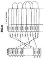
- Fig.10 is an illustration for explaining rearrangement in the X-direction.
- the rearrangement in the X-direction is processed similarly to that in the Y-direction, in which an Xmin in its line is obtained, then the rearrangement is performed using the obtained value.
- a fragment at which a polygon becomes valid for the first time (that is, the polygon that makes a fragment concerned valid for the first time) is found. For example, as shown in Fig.11, a fragment of the least X-coordinate value is selected among the least Y-coordinate values in each polygon.
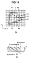
- polygons that become invalid in the fragments subsequently processed are removed from the links.
- fragments F1 to F7 are removed from the X LINK after the rendering.
- the fragment F7 is also removed from the Y LINK after the rendering.
- a polygon's valid region obtained by performing the link update is exemplified in Fig.13(b).
- the Y-directional link processing is also performed with respect to the Y-direction by the identical procedures.
- the polygons are rearranged in both the vertical direction and the horizontal direction to a scanning line, thus polygons included in each fragment being able to be retrieved. Since this retrieved information is used and the polygons are divided every fragment now concerned, it is possible to read and process polygons included in each fragment, without producing polygons newly.
- a huge amount of calculation necessary for dividing all the polygons every fragment to be processed can be eliminated and it is not necessary to install a storage with greater amounts of capacity that has been needed to store information about the polygons produced by the division.
- the processing time is reduced and it is possible to realize systems in which only a smaller capacity of storage is required. In other words, cost-saving and high-performance systems can be achieved.
- Such systems are also attributed to the fact that the processing of the polygons for the semitransparent nature is separated for opaque polygons, polygons with transparent pixels, and semitransparent polygons and the semitransparent polygons are processed at the last stage.
- objects to be processed are sectioned into types of opaque polygons, polygons with transparent pixels, and semitransparent polygons, then processed in the order of the opaque polygons, the polygons with transparent pixels, and the semitransparent polygons, so that the semitransparent polygons can be processed even when texture data are given the polygons.
Landscapes
- Engineering & Computer Science (AREA)
- Physics & Mathematics (AREA)
- General Physics & Mathematics (AREA)
- Theoretical Computer Science (AREA)
- Computer Graphics (AREA)
- Image Generation (AREA)
- Image Processing (AREA)
- Image Input (AREA)
Description
Claims (10)
- An image processor in which a screen is divided into regions of a predetermined size, and processing on polygon data is performed region by region, comprising first rearranging means for providing constituting elements of a plurality of polygons, falling into individual regions on the screen in a direction vertical to a scanning line, with vertical links mutually linking constituting elements of a polygon, and for rearranging links to constituting elements falling into the same region, thus linking these elements;
second rearranging means for providing constituting elements of a plurality of polygons, falling into individual regions on the screen in the direction of the scanning line, with horizontal links mutually linking constituting elements of a polygon, and for rearranging links to constituting elements falling into the same region, thus linking these elements; and
an image processing means for
retrieving and processing constituting elements of diverse polygons falling in a given region, the sequence of constituting elements being given by rearranged links. - An image processor according to claim 1, wherein
the first rearranging means is operable to perform the rearrangement based on minimum or maximum values of the constituting elements with reference to the vertical direction; and
the second rearranging means is operable to perform the rearrangement based on minimum or maximum values of the constituting elements with reference to the horizontal direction, in vertical coordinates of a region to be processed by the first rearranging means. - An image processor according to claim 1 or claim 2, wherein the first and second rearranging means determine whether or not, after completion of the processing of a polygon in the image processing means for a said region, the constituting elements for said polygon to be used by the image processing means are included in a region to be image-processed at the next processing, and perform link update processing which removes from the link the constituting elements which are determined to not be included.
- An image processor according to any preceding claim, wherein the image processing means, as to image processing for each divided region, not only sections polygons to be processed into opaque polygons, polygons with transparent pixels, and semitransparent polygons but also processes in the order of the opaque polygons, polygons with transparent pixels, and semitransparent polygons.
- An image processing method by which a screen is divided into regions of a predetermined size, and processing on polygon data is performed region by region, the method comprising the steps of:a first rearranging step of providing constituting elements of a plurality of polygons, falling into individual regions on the screen in a direction vertical to a scanning line, with vertical links mutually linking constituting elements of a polygon, and rearranging links to constituting elements falling into the same region, thus linking these elements;a second rearranging step offor providing constituting elements of a plurality of polygons, falling into individual regions on the screen in the direction of the scanning line, with horizontal links mutually linking constituting elements of a polygon, and rearranging links to constituting elements falling into the same region, thus linking these elements; andan image processing step ofretrieving and processing constituting elements of diverse polygons falling in a given region, the sequence of constituting elements being given by rearranged links.
- A method according to claim 5, wherein,
in the first rearranging step, the rearrangement is performed based on minimum or maximum values of the constituting elements with reference to the vertical direction, and
in the second rearranging step, the rearrangement is performed based on minimum or maximum values of the constituting elements with reference to the horizontal direction, in vertical coordinates of a region to be processed in the first rearranging step. - A method according to claim 5 or claim 6, wherein in the first and second rearranging steps, link update processing is performed to invalidate an unnecessary region among the regions corresponding to the constituting elements.
- A method according to any one of claims 5 to 7, wherein in the image processing step, the image processing for each divided region is performed with polygons to be processed sectioned into opaque polygons, polygons with transparent pixels, and semitransparent polygons, and performed in the order of the opaque polygons, polygons with transparent pixels, and semitransparent polygons.
- An image processor according to any of claims 1 to 4, including:a memory buffer arranged to memorize said constituting elements and links; andan index buffer arranged to memorize, for every divided region, a location of memorization of at least one of the constituting elements among the constituting elements included in that region; and whereinsaid image processing means reads from the memory buffer by reference to the index buffer constituting elements included in regions at which the processing is to be performed and performs desired image processing.
- An image processor according to claim 9, wherein the index buffer has a vertical-position index buffer memorizing, for every divided region in the direction vertical to the scanning line, a location of memorization of at least one of the image constituting elements among the constituting elements included in said divided regions at the positions in said vertical direction and a horizontal-position index buffer memorizing, for every divided region in the direction horizontal to the scanning line, a location of memorization of at least one of the image constituting elements among the constituting elements included in said divided regions at the positions in said horizontal direction.
Applications Claiming Priority (3)
| Application Number | Priority Date | Filing Date | Title |
|---|---|---|---|
| JP13183197 | 1997-05-22 | ||
| JP9131831A JPH10320573A (en) | 1997-05-22 | 1997-05-22 | Image processing apparatus and image processing method |
| PCT/JP1998/002262 WO1998053425A1 (en) | 1997-05-22 | 1998-05-22 | Image processor and image processing method |
Publications (3)
| Publication Number | Publication Date |
|---|---|
| EP0984392A1 EP0984392A1 (en) | 2000-03-08 |
| EP0984392A4 EP0984392A4 (en) | 2001-04-25 |
| EP0984392B1 true EP0984392B1 (en) | 2004-06-23 |
Family
ID=15067125
Family Applications (1)
| Application Number | Title | Priority Date | Filing Date |
|---|---|---|---|
| EP98921774A Expired - Lifetime EP0984392B1 (en) | 1997-05-22 | 1998-05-22 | Image processor and image processing method |
Country Status (8)
| Country | Link |
|---|---|
| US (1) | US6680741B1 (en) |
| EP (1) | EP0984392B1 (en) |
| JP (1) | JPH10320573A (en) |
| KR (1) | KR20010012841A (en) |
| CN (1) | CN1122945C (en) |
| DE (1) | DE69824725D1 (en) |
| TW (1) | TW375719B (en) |
| WO (1) | WO1998053425A1 (en) |
Families Citing this family (18)
| Publication number | Priority date | Publication date | Assignee | Title |
|---|---|---|---|---|
| GB2362552B (en) * | 1999-06-28 | 2003-12-10 | Clearspeed Technology Ltd | Processing graphical data |
| GB2355633A (en) * | 1999-06-28 | 2001-04-25 | Pixelfusion Ltd | Processing graphical data |
| US6728862B1 (en) | 2000-05-22 | 2004-04-27 | Gazelle Technology Corporation | Processor array and parallel data processing methods |
| JP3466173B2 (en) * | 2000-07-24 | 2003-11-10 | 株式会社ソニー・コンピュータエンタテインメント | Image processing system, device, method and computer program |
| JP3966832B2 (en) | 2003-04-28 | 2007-08-29 | 株式会社東芝 | Drawing processing apparatus and drawing processing method |
| KR100434178B1 (en) * | 2003-12-16 | 2004-06-09 | 엔에이치엔(주) | A method of adjusting precision of image data which inter-locked with video signals throughput of a terminal and a system thereof |
| US7573599B2 (en) * | 2004-05-20 | 2009-08-11 | Primax Electronics Ltd. | Method of printing geometric figures |
| US7519233B2 (en) * | 2005-06-24 | 2009-04-14 | Microsoft Corporation | Accumulating transforms through an effect graph in digital image processing |
| WO2007064280A1 (en) | 2005-12-01 | 2007-06-07 | Swiftfoot Graphics Ab | Computer graphics processor and method for rendering a three-dimensional image on a display screen |
| JP4621617B2 (en) * | 2006-03-28 | 2011-01-26 | 株式会社東芝 | Graphic drawing apparatus, graphic drawing method, and program |
| EP2171647A2 (en) * | 2007-07-13 | 2010-04-07 | Marvell World Trade Ltd. | Laser oscillating mirror support for color printer |
| CN101127207B (en) * | 2007-09-26 | 2010-06-02 | 北大方正集团有限公司 | A method and device for improving the display quality of gray-scale fonts |
| JP2011086235A (en) * | 2009-10-19 | 2011-04-28 | Fujitsu Ltd | Image processing apparatus, image processing method, and image processing program |
| WO2012037157A2 (en) * | 2010-09-13 | 2012-03-22 | Alt Software (Us) Llc | System and method for displaying data having spatial coordinates |
| CN102572205B (en) * | 2011-12-27 | 2014-04-30 | 方正国际软件有限公司 | Image processing method, device and system |
| CN113628102B (en) * | 2021-08-16 | 2024-09-10 | 广东三维家信息科技有限公司 | Entity model blanking method and device, electronic equipment and storage medium |
| US20250201164A1 (en) * | 2023-12-15 | 2025-06-19 | Novatek Microelectronics Corp. | Method for driving display panel and driver circuit using the same |
| CN118298774A (en) * | 2024-04-16 | 2024-07-05 | 深圳市威勤电子技术有限公司 | A method for realizing LCD display sub-area control |
Family Cites Families (4)
| Publication number | Priority date | Publication date | Assignee | Title |
|---|---|---|---|---|
| US4885703A (en) * | 1987-11-04 | 1989-12-05 | Schlumberger Systems, Inc. | 3-D graphics display system using triangle processor pipeline |
| JPH0371378A (en) * | 1989-08-11 | 1991-03-27 | Daikin Ind Ltd | Method and device for display of transparency |
| JP3092131B2 (en) * | 1989-12-28 | 2000-09-25 | 日本電気株式会社 | Image generation device |
| JPH04170686A (en) * | 1990-11-05 | 1992-06-18 | Canon Inc | Image processor |
-
1997
- 1997-05-22 JP JP9131831A patent/JPH10320573A/en not_active Withdrawn
-
1998
- 1998-05-22 CN CN98805330A patent/CN1122945C/en not_active Expired - Fee Related
- 1998-05-22 KR KR19997010806A patent/KR20010012841A/en not_active Withdrawn
- 1998-05-22 US US09/424,424 patent/US6680741B1/en not_active Expired - Fee Related
- 1998-05-22 DE DE69824725T patent/DE69824725D1/en not_active Expired - Lifetime
- 1998-05-22 TW TW087108115A patent/TW375719B/en active
- 1998-05-22 EP EP98921774A patent/EP0984392B1/en not_active Expired - Lifetime
- 1998-05-22 WO PCT/JP1998/002262 patent/WO1998053425A1/en not_active Ceased
Also Published As
| Publication number | Publication date |
|---|---|
| JPH10320573A (en) | 1998-12-04 |
| US6680741B1 (en) | 2004-01-20 |
| DE69824725D1 (en) | 2004-07-29 |
| TW375719B (en) | 1999-12-01 |
| EP0984392A1 (en) | 2000-03-08 |
| WO1998053425A1 (en) | 1998-11-26 |
| KR20010012841A (en) | 2001-02-26 |
| CN1275225A (en) | 2000-11-29 |
| CN1122945C (en) | 2003-10-01 |
| EP0984392A4 (en) | 2001-04-25 |
Similar Documents
| Publication | Publication Date | Title |
|---|---|---|
| US6680741B1 (en) | Image processor and image processing method | |
| US6411294B1 (en) | Image display apparatus and image display method | |
| US10043306B2 (en) | Using depth data in a graphics processing system | |
| US9741159B2 (en) | Graphics processing systems | |
| US11861760B2 (en) | Tile-based graphics processing | |
| US5852443A (en) | Method and system for memory decomposition in a graphics rendering system | |
| US6038031A (en) | 3D graphics object copying with reduced edge artifacts | |
| US5699497A (en) | Rendering global macro texture, for producing a dynamic image, as on computer generated terrain, seen from a moving viewpoint | |
| JP5188628B2 (en) | Method and system for rendering a 3D model of a 3D object | |
| CN112270756A (en) | Data rendering method applied to BIM model file | |
| GB2561557A (en) | Method of and apparatus for processing graphics | |
| KR20140131270A (en) | Graphics processing systems | |
| KR19980702804A (en) | Hardware Architecture for Image Generation and Manipulation | |
| US10997756B2 (en) | Processing of primitives in a graphics processor | |
| US20150109313A1 (en) | Method of and apparatus for processing graphics | |
| GB2525223A (en) | Graphics processing systems | |
| JPH11328441A (en) | Graphics display control method and computer graphics | |
| US20050088450A1 (en) | Texture roaming via dimension elevation | |
| US20140327688A1 (en) | Graphics processing systems | |
| US20020135587A1 (en) | System and method for implementing accumulation buffer operations in texture mapping hardware | |
| US10726610B2 (en) | Efficient graphics processing using metadata | |
| EP1058912B1 (en) | Subsampled texture edge antialiasing | |
| US20050017982A1 (en) | Dynamic imposter generation with MIP map anti-aliasing | |
| US11908069B2 (en) | Graphics processing | |
| US7646385B2 (en) | Computer graphics rendering method and apparatus |
Legal Events
| Date | Code | Title | Description |
|---|---|---|---|
| PUAI | Public reference made under article 153(3) epc to a published international application that has entered the european phase |
Free format text: ORIGINAL CODE: 0009012 |
|
| 17P | Request for examination filed |
Effective date: 19991213 |
|
| AK | Designated contracting states |
Kind code of ref document: A1 Designated state(s): DE ES FR GB IT |
|
| A4 | Supplementary search report drawn up and despatched |
Effective date: 20010313 |
|
| AK | Designated contracting states |
Kind code of ref document: A4 Designated state(s): DE ES FR GB IT |
|
| RIC1 | Information provided on ipc code assigned before grant |
Free format text: 7G 06T 1/00 A, 7G 06T 11/40 B, 7G 06T 15/50 B |
|
| 17Q | First examination report despatched |
Effective date: 20030328 |
|
| GRAP | Despatch of communication of intention to grant a patent |
Free format text: ORIGINAL CODE: EPIDOSNIGR1 |
|
| GRAS | Grant fee paid |
Free format text: ORIGINAL CODE: EPIDOSNIGR3 |
|
| GRAA | (expected) grant |
Free format text: ORIGINAL CODE: 0009210 |
|
| AK | Designated contracting states |
Kind code of ref document: B1 Designated state(s): DE ES FR GB IT |
|
| PG25 | Lapsed in a contracting state [announced via postgrant information from national office to epo] |
Ref country code: IT Free format text: LAPSE BECAUSE OF FAILURE TO SUBMIT A TRANSLATION OF THE DESCRIPTION OR TO PAY THE FEE WITHIN THE PRESCRIBED TIME-LIMIT;WARNING: LAPSES OF ITALIAN PATENTS WITH EFFECTIVE DATE BEFORE 2007 MAY HAVE OCCURRED AT ANY TIME BEFORE 2007. THE CORRECT EFFECTIVE DATE MAY BE DIFFERENT FROM THE ONE RECORDED. Effective date: 20040623 Ref country code: FR Free format text: LAPSE BECAUSE OF FAILURE TO SUBMIT A TRANSLATION OF THE DESCRIPTION OR TO PAY THE FEE WITHIN THE PRESCRIBED TIME-LIMIT Effective date: 20040623 |
|
| REG | Reference to a national code |
Ref country code: GB Ref legal event code: FG4D |
|
| REF | Corresponds to: |
Ref document number: 69824725 Country of ref document: DE Date of ref document: 20040729 Kind code of ref document: P |
|
| PG25 | Lapsed in a contracting state [announced via postgrant information from national office to epo] |
Ref country code: DE Free format text: LAPSE BECAUSE OF FAILURE TO SUBMIT A TRANSLATION OF THE DESCRIPTION OR TO PAY THE FEE WITHIN THE PRESCRIBED TIME-LIMIT Effective date: 20040924 |
|
| PG25 | Lapsed in a contracting state [announced via postgrant information from national office to epo] |
Ref country code: ES Free format text: LAPSE BECAUSE OF FAILURE TO SUBMIT A TRANSLATION OF THE DESCRIPTION OR TO PAY THE FEE WITHIN THE PRESCRIBED TIME-LIMIT Effective date: 20041004 |
|
| PLBE | No opposition filed within time limit |
Free format text: ORIGINAL CODE: 0009261 |
|
| STAA | Information on the status of an ep patent application or granted ep patent |
Free format text: STATUS: NO OPPOSITION FILED WITHIN TIME LIMIT |
|
| 26N | No opposition filed |
Effective date: 20050324 |
|
| EN | Fr: translation not filed | ||
| PGFP | Annual fee paid to national office [announced via postgrant information from national office to epo] |
Ref country code: GB Payment date: 20090522 Year of fee payment: 12 |
|
| GBPC | Gb: european patent ceased through non-payment of renewal fee |
Effective date: 20100522 |
|
| PG25 | Lapsed in a contracting state [announced via postgrant information from national office to epo] |
Ref country code: GB Free format text: LAPSE BECAUSE OF NON-PAYMENT OF DUE FEES Effective date: 20100522 |