EP0984073B1 - Making and using thermal spray masks carrying thermoset epoxy coating - Google Patents
Making and using thermal spray masks carrying thermoset epoxy coating Download PDFInfo
- Publication number
- EP0984073B1 EP0984073B1 EP99306795A EP99306795A EP0984073B1 EP 0984073 B1 EP0984073 B1 EP 0984073B1 EP 99306795 A EP99306795 A EP 99306795A EP 99306795 A EP99306795 A EP 99306795A EP 0984073 B1 EP0984073 B1 EP 0984073B1
- Authority
- EP
- European Patent Office
- Prior art keywords
- coating
- mask
- masks
- thermoset
- particles
- Prior art date
- Legal status (The legal status is an assumption and is not a legal conclusion. Google has not performed a legal analysis and makes no representation as to the accuracy of the status listed.)
- Expired - Lifetime
Links
- 229920001187 thermosetting polymer Polymers 0.000 title claims description 24
- 239000007921 spray Substances 0.000 title description 17
- 229920006334 epoxy coating Polymers 0.000 title description 3
- 238000000576 coating method Methods 0.000 claims description 33
- 239000011248 coating agent Substances 0.000 claims description 32
- 239000004593 Epoxy Substances 0.000 claims description 13
- 238000000034 method Methods 0.000 claims description 10
- 238000005507 spraying Methods 0.000 claims description 9
- IISBACLAFKSPIT-UHFFFAOYSA-N bisphenol A Chemical compound C=1C=C(O)C=CC=1C(C)(C)C1=CC=C(O)C=C1 IISBACLAFKSPIT-UHFFFAOYSA-N 0.000 claims description 5
- 239000003795 chemical substances by application Substances 0.000 claims description 4
- 238000007524 flame polishing Methods 0.000 claims description 4
- 238000004519 manufacturing process Methods 0.000 claims description 4
- 239000011148 porous material Substances 0.000 claims description 4
- 239000000758 substrate Substances 0.000 claims description 4
- 230000000694 effects Effects 0.000 claims description 2
- 239000012948 isocyanate Substances 0.000 claims description 2
- 150000002513 isocyanates Chemical class 0.000 claims description 2
- 229920000728 polyester Polymers 0.000 claims description 2
- 239000004606 Fillers/Extenders Substances 0.000 claims 1
- 239000002245 particle Substances 0.000 description 30
- 239000000843 powder Substances 0.000 description 14
- 229910052751 metal Inorganic materials 0.000 description 13
- 239000002184 metal Substances 0.000 description 13
- 239000000919 ceramic Substances 0.000 description 11
- 238000007751 thermal spraying Methods 0.000 description 7
- RYGMFSIKBFXOCR-UHFFFAOYSA-N Copper Chemical compound [Cu] RYGMFSIKBFXOCR-UHFFFAOYSA-N 0.000 description 6
- 229910052802 copper Inorganic materials 0.000 description 6
- 239000010949 copper Substances 0.000 description 6
- 239000000203 mixture Substances 0.000 description 6
- 229910000831 Steel Inorganic materials 0.000 description 5
- 239000007789 gas Substances 0.000 description 5
- 239000006223 plastic coating Substances 0.000 description 5
- 239000010959 steel Substances 0.000 description 5
- 238000010438 heat treatment Methods 0.000 description 4
- 239000000567 combustion gas Substances 0.000 description 3
- 239000000446 fuel Substances 0.000 description 3
- 239000000463 material Substances 0.000 description 3
- 150000002739 metals Chemical class 0.000 description 3
- 239000011253 protective coating Substances 0.000 description 3
- ATUOYWHBWRKTHZ-UHFFFAOYSA-N Propane Chemical compound CCC ATUOYWHBWRKTHZ-UHFFFAOYSA-N 0.000 description 2
- 239000003570 air Substances 0.000 description 2
- TZCXTZWJZNENPQ-UHFFFAOYSA-L barium sulfate Chemical compound [Ba+2].[O-]S([O-])(=O)=O TZCXTZWJZNENPQ-UHFFFAOYSA-L 0.000 description 2
- 238000004132 cross linking Methods 0.000 description 2
- 238000005516 engineering process Methods 0.000 description 2
- 239000010410 layer Substances 0.000 description 2
- 238000013021 overheating Methods 0.000 description 2
- 239000004033 plastic Substances 0.000 description 2
- 229920003023 plastic Polymers 0.000 description 2
- 229920000642 polymer Polymers 0.000 description 2
- 229920005989 resin Polymers 0.000 description 2
- 239000011347 resin Substances 0.000 description 2
- 229910001220 stainless steel Inorganic materials 0.000 description 2
- 239000010935 stainless steel Substances 0.000 description 2
- 239000000126 substance Substances 0.000 description 2
- 229910000744 A-2 tool steel Inorganic materials 0.000 description 1
- 229910000906 Bronze Inorganic materials 0.000 description 1
- VYZAMTAEIAYCRO-UHFFFAOYSA-N Chromium Chemical compound [Cr] VYZAMTAEIAYCRO-UHFFFAOYSA-N 0.000 description 1
- BRLQWZUYTZBJKN-UHFFFAOYSA-N Epichlorohydrin Chemical compound ClCC1CO1 BRLQWZUYTZBJKN-UHFFFAOYSA-N 0.000 description 1
- 239000004677 Nylon Substances 0.000 description 1
- NPXOKRUENSOPAO-UHFFFAOYSA-N Raney nickel Chemical compound [Al].[Ni] NPXOKRUENSOPAO-UHFFFAOYSA-N 0.000 description 1
- 239000004809 Teflon Substances 0.000 description 1
- 229920006362 Teflon® Polymers 0.000 description 1
- ATJFFYVFTNAWJD-UHFFFAOYSA-N Tin Chemical compound [Sn] ATJFFYVFTNAWJD-UHFFFAOYSA-N 0.000 description 1
- YKTSYUJCYHOUJP-UHFFFAOYSA-N [O--].[Al+3].[Al+3].[O-][Si]([O-])([O-])[O-] Chemical compound [O--].[Al+3].[Al+3].[O-][Si]([O-])([O-])[O-] YKTSYUJCYHOUJP-UHFFFAOYSA-N 0.000 description 1
- 230000002745 absorbent Effects 0.000 description 1
- 239000002250 absorbent Substances 0.000 description 1
- 230000004931 aggregating effect Effects 0.000 description 1
- 229910052782 aluminium Inorganic materials 0.000 description 1
- XAGFODPZIPBFFR-UHFFFAOYSA-N aluminium Chemical compound [Al] XAGFODPZIPBFFR-UHFFFAOYSA-N 0.000 description 1
- PNEYBMLMFCGWSK-UHFFFAOYSA-N aluminium oxide Inorganic materials [O-2].[O-2].[O-2].[Al+3].[Al+3] PNEYBMLMFCGWSK-UHFFFAOYSA-N 0.000 description 1
- 230000005540 biological transmission Effects 0.000 description 1
- 238000005422 blasting Methods 0.000 description 1
- 239000010974 bronze Substances 0.000 description 1
- 239000006229 carbon black Substances 0.000 description 1
- 229910010293 ceramic material Inorganic materials 0.000 description 1
- 229910052804 chromium Inorganic materials 0.000 description 1
- 239000011651 chromium Substances 0.000 description 1
- 238000004140 cleaning Methods 0.000 description 1
- 238000002485 combustion reaction Methods 0.000 description 1
- 239000002131 composite material Substances 0.000 description 1
- 239000007859 condensation product Substances 0.000 description 1
- 238000011109 contamination Methods 0.000 description 1
- 229910052593 corundum Inorganic materials 0.000 description 1
- 230000002950 deficient Effects 0.000 description 1
- 238000005137 deposition process Methods 0.000 description 1
- 238000005474 detonation Methods 0.000 description 1
- 125000003700 epoxy group Chemical group 0.000 description 1
- 239000011152 fibreglass Substances 0.000 description 1
- 238000011049 filling Methods 0.000 description 1
- 239000010419 fine particle Substances 0.000 description 1
- 238000009413 insulation Methods 0.000 description 1
- -1 layout blueing Substances 0.000 description 1
- 230000000873 masking effect Effects 0.000 description 1
- 239000000155 melt Substances 0.000 description 1
- 230000008018 melting Effects 0.000 description 1
- 238000002844 melting Methods 0.000 description 1
- 238000002156 mixing Methods 0.000 description 1
- 239000003607 modifier Substances 0.000 description 1
- 229920001778 nylon Polymers 0.000 description 1
- 229920000647 polyepoxide Polymers 0.000 description 1
- 229920002635 polyurethane Polymers 0.000 description 1
- 239000004814 polyurethane Substances 0.000 description 1
- 239000001294 propane Substances 0.000 description 1
- 230000001681 protective effect Effects 0.000 description 1
- 239000011241 protective layer Substances 0.000 description 1
- 230000001105 regulatory effect Effects 0.000 description 1
- 239000004576 sand Substances 0.000 description 1
- 238000007711 solidification Methods 0.000 description 1
- 230000008023 solidification Effects 0.000 description 1
- 230000003746 surface roughness Effects 0.000 description 1
- BFKJFAAPBSQJPD-UHFFFAOYSA-N tetrafluoroethene Chemical group FC(F)=C(F)F BFKJFAAPBSQJPD-UHFFFAOYSA-N 0.000 description 1
- 238000011282 treatment Methods 0.000 description 1
- 229910001845 yogo sapphire Inorganic materials 0.000 description 1
Images


Classifications
-
- C—CHEMISTRY; METALLURGY
- C23—COATING METALLIC MATERIAL; COATING MATERIAL WITH METALLIC MATERIAL; CHEMICAL SURFACE TREATMENT; DIFFUSION TREATMENT OF METALLIC MATERIAL; COATING BY VACUUM EVAPORATION, BY SPUTTERING, BY ION IMPLANTATION OR BY CHEMICAL VAPOUR DEPOSITION, IN GENERAL; INHIBITING CORROSION OF METALLIC MATERIAL OR INCRUSTATION IN GENERAL
- C23C—COATING METALLIC MATERIAL; COATING MATERIAL WITH METALLIC MATERIAL; SURFACE TREATMENT OF METALLIC MATERIAL BY DIFFUSION INTO THE SURFACE, BY CHEMICAL CONVERSION OR SUBSTITUTION; COATING BY VACUUM EVAPORATION, BY SPUTTERING, BY ION IMPLANTATION OR BY CHEMICAL VAPOUR DEPOSITION, IN GENERAL
- C23C4/00—Coating by spraying the coating material in the molten state, e.g. by flame, plasma or electric discharge
- C23C4/01—Selective coating, e.g. pattern coating, without pre-treatment of the material to be coated
-
- B—PERFORMING OPERATIONS; TRANSPORTING
- B05—SPRAYING OR ATOMISING IN GENERAL; APPLYING FLUENT MATERIALS TO SURFACES, IN GENERAL
- B05B—SPRAYING APPARATUS; ATOMISING APPARATUS; NOZZLES
- B05B16/00—Spray booths
- B05B16/60—Ventilation arrangements specially adapted therefor
Definitions
- This invention relates to the technology of thermal spraying metals or ceramics, and, more particularly, to the technology of providing a low cost, flexible, self-leveling, non peelable, self-adhering coating on masks that will deflect thermally sprayed particles and prevent adherence to the mask.
- Thermal spraying techniques will deposit very hot viscous particles (greater than 700°C) onto a target surface usually 7,62 - 30,48 cm (3-12 inches)away from the spray gun nozzle. Although techniques are available to generally control and focus the spray as a conical pattern, such sprayed pattern cannot be controlled to match all edges of the target. Accordingly, there must be a certain degree of overlap beyond the precise target edges to obtain the proper coating thickness, area definition, and physical characteristics. Accordingly, masks are used to cover surfaces adjacent to the intended coated edges to prevent adherence. Masks are usually metallic, such as polished stainless steel, to provide a smooth surface that can withstand the high heat content of the sprayed particles.
- Applicant has tried several alternative protective coatings or treatments on such masks to protect them from the thermal spray, such as TiN, hard chromium, layout blueing, teflon, A2 toolsteel, cast nylon, and aluminum silicate ceramic.
- such alternatives have proven to be deficient because either they are to expensive for use, or the protective coating is too viscous, absorbent, or porous to deflect the thermal spray particles, or the protective film roughens the mask surface to allow a build up of the spray coating on the mask.
- applicant has tried temporary films to protect the masking, such as use of shiny smooth aluminum fiberglass reinforced tape; such tapes have failed to provide durability and have had to be removed and replaced frequently.
- United States Patent 2,958,609 describes a process for providing protective coatings, which comprises the steps of pulverising the condensation product formed from diphenylol propane and epichlorhydrin, mixing it in cold state with a pulverant hardening agent, and heat-spraying the mixture upon an exposed surface, whereby the mixture melts during the spraying to form a quick hardening protective layer.
- JP59076868 describes a mask which is useful for spraying metal or ceramics on to desired parts of a workpiece. The mask comprises a metal plate punched into a pre-determined pattern and having a layer of tetrafluorethylene resin formed on the outer surface of the metal plate.
- the invention is a method of making a mask assembly by (i) providing a heat resistance mask substrate having an exposed surface with a surface smoothness less than 50.8 ⁇ m (2000 micro inches); (ii) uniformly spraying a thermoset epoxy organic coating onto such exposed surface in one or more layers to provide a coating having (e.g., a thickness equal to or less than about 0.0127 cms (0.005 inches)) a smoothness characterized by an average profilometer reading (Ra) of no greater than 1.5 ⁇ m (micrometers), said coating being devoid of pores that exceed about 0.0127 cms (0.005 inches) in size; and (iii) flame polishing all or a portion of such coating to effect a surface finish of about 1.0 ⁇ m (micrometers).
- a coating having (e.g., a thickness equal to or less than about 0.0127 cms (0.005 inches)) a smoothness characterized by an average profilometer reading (Ra) of no greater than 1.5 ⁇ m (micrometers), said coating being devoid
- the improved mask assembly and the method of making such assembly is not only economical, but will be durable and withstand the high heat of thermal spraying particles after hundreds of independent spray cycles.
- the mask assembly and the method of making the mask assembly present an outer coated mask surface that is self levelling, smooth and shiny, and virtually eliminate adherence of thermally sprayed particles thereagainst during the useful life of the mask.
- thermoset epoxy material previously applied to masks.
- thermoset epoxy coating is not melted upon impact by the thermally sprayed metal or ceramic droplets.
- Such coated masks eliminate the need for cleaning while providing a much longer service life.
- the absence of even lightly adhering metallic or ceramic particles to the coated masks eliminate the risk that such lightly adhering particles will peel off and contaminate the desired deposit of thermally sprayed particles.
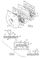
- FIG. 1 illustrates several different stainless masks 10, 11, 12, 13 that are used to define different micro circuitries for automotive electrical control components. Copper is sprayed through openings in the masks (such as indicated at 14, 15 and 16) onto an insulated substrate. Unfortunately copper sticks well to the mask's raw stainless surface 17; repeated use of such uncoated masks in creating several independent circuits will result in a rapid buildup of copper on the exposed surface of the mask allowing later deposited copper particles to flake off or peel off causing contamination of the desired circuit on the insulated board.
- Figure 4 further illustrates the use of two different types of masks, one mask 18 is used to cover the deck surface 19 surrounding one end 20a of an engine cylinder bore 20, and another mask 21 is used in the crank bore area 22 in the form of a tube angled at 23 to register with the other end 20b of the cylinder bore 20.
- Figure 2 illustrates the steps of the process embodying the invention as applied to making a coated flat mask 25 useful for spraying electrical circuitry on a flat insulation board.
- a stainless steel sheet stamped with the desired cut-out openings defining the circuitry pattern, has an exposed surface 26 prepared to receive the plastic coating 27. Such surface may be primed or sand blasted to promote adhesion of the coating.
- the prepared surface is sprayed with a thermoset polymer (epoxy or polyester) 28 to form the coating 27.
- Thermoset materials when heated, will undergo chemical change; their molecules will cross-link to create a different composition in the heated coating.
- a preferred composition is an epoxy powder comprised of, by weight, about 50% Bisphenol A resin, about 11% isocyanate curing agent, and the remainder essentially a barium sulfate curing agent.
- Flow modifiers, carbon black, Al 2 O 3 may be present in very small amounts aggregating less than 3% by weight.
- Longer chain polymers obtain a smoother as-sprayed surface finish, such as polyurethane, which may be even more desirable as a mask coating.
- suitable commercial thermoset epoxies include the tradenames DOW 667, and Ferro VE309. Self-adherence is promoted by grit blasting the receiving surface and self-leveling is obtained because of the inherent viscosity of the melted epoxy powder.
- the particle size of the thermoset powder is advantageously 50-100 ⁇ m (microns), with fine particles limited to 0-15% +200 mesh and 30-40% +325 mesh.
- plastic spraying can be carried out by electrostatic means 29 which requires that the cold applied coating 27 of thermoset powder be subjected to heating in an oven 30 to bake and initiate the necessary cross-linking of the polymer.
- the oven chamber 31 is heated to about 190°C (375°F) and the coated mask allowed to dwell therein (on a conveyor 32) for a period of about 8 minutes, although the powder will gel in 15-40 seconds.
- thermoset epoxy powder to cross-linking heating as part of the deposition process and thereby avoids separate heating.
- the flame spray gun may be of the oxy-fuel type where the thermoset expoy powder is fluidized by compressed air and fed into the flame of the gun. The powder is injected at high velocity through the flame of the fuel, such as propane, just long enough to allow complete melting of the powder particles. The molten particles, in the form of highly viscous droplets, deposit on the mask, forming a smooth self-leveling film upon solidification.
- the flame spray gun usually has a body provided with air, combustion gas, and powder material supply channels.
- Coating quality may be increased when using liquefied gas by having the axis of the combustion gas outlet channel at an angle of 6-9° to the axis of the powder channel, thereby forming a converging flame.
- the amounts of air, combustion gas and powder feed are regulated by control valves.
- the air and liquefied gas mix in chambers forming a combustible mixture that flows to the mouth piece nozzle. As a result, the powder particles, entering the flame, are heated and applied in a molten form onto the mask surface.
- the deposited coating thickness 33 must be uniform and not be greater than about 0.127cms (.005 inches) to (i) prevent overheating the coating when flame sprayed, (ii) avoid reflow of the viscous particles by later deposited particles causing non uniformity, and (iii) avoid opening pores in the deposit. Particularly with non-flat masks, such as dishes, cones or tubes, the coating thickness 33 must follow the mask surface 26 uniformly and be in the thickness range required.
- the standard deviation for smoothness of the as deposited coating is ⁇ 25% of the coating thickness.
- Surface roughness of the thermoset plastic coating is in the range of .16-1.2 ⁇ m Ra (microns).
- the coating 27 has a porosity of less than 25% and is devoid of pores greater than 0.127 cms (0.005 inches) in size in the exposed surface.
- flame polishing is used as shown in Figure 2; a hot combustion flame 34 is brought into contact with the coating 27 and moved there across to reflow the outer skin of the coating 27. It is critical to control the dwell time of the flame on any one spot of the coating to less than 5 seconds to avoid overheating the thermoset epoxy plastic and burning the coating. Slight reflow of the coating during flame polishing will result in an enhanced surface smoothness to about 1.0 ⁇ m (microns) (Ra), which further facilitates the ability of the coating to ward off adherence of any metal or ceramic particles.
- thermoset plastic coated masks 25 achieve a new level of performance in protecting articles subjected to thermally sprayed metals or ceramics.
- thermoset coated mask 40 As shown in Figure 3, one use mode for the coated masks is illustrated; copper is thermally sprayed at 39 through a thermoset coated mask 40 onto a insulating circuit board 41.
- the super hot viscous copper particles 42 emitted from the spray gun 43 carried on a robot 45, will bounce off the thermoset plastic coating to be entrained in an exhaust flow 44 (created in the spray chamber 46) for collection and reuse.
- the temperature of the metal or ceramic particles, as they hit the mask or previously layed down thermoset coating are in the range of 875-1200°C.
- Extensive trials of the coated masks obtained by the process according to this invention, have withstood several hundred thermal-spraying cycles with little or no evidence of any adherence of metal or ceramic particles thereto. Most importantly, there is no evidence of metal or ceramic particles building up which can be later peeled or dislodged from the masks to contaminate the useful article being thermally sprayed.
- Thermal spraying of metals or ceramics, onto such protected masks can involve use of various types of guns (powder plasma, singular or double wire-arc, oxy-fuel, or even detonation).
- Thermoset epoxy coated masks as shown in Figure 4 are used to protect against wire-arc sprayed steel.
- an annular dish or conically shaped coated mask 18 is placed on the deck surface 19 around the mouth of a cylinder bore 20 of an automotive engine block 47.
- Another mask 21, in the form of an angled tube, coated with thermoset polymer on its interior 48 is stationed at the crank case end 20b of the cylinder bore to protect the crank case area and allow for the through flow of exhaust gases 49 from the gun to entrain and carry away loose steel particles bouncing off the plastic coating of the masks.
- a thermal spray gun 50 rotating about a longitudinal axis 51, is moved into and along the length of the cylinder bore.
- Several different coatings may be applied by thermal spraying to the interior of the bores such as an initial bond coat consisting of nickel-aluminum, and then subsequently a top coat which is primarily constituted of steel.
- the particular gun that was utilized in the illustration of Figure 4 is a plasma transferred wire-arc spray type wherein an arc is first established between a cathode and its nozzle; after creating a plasma as a result of gas flowing through such arc, the plasma and arc are transferred to the wire tip acting as a secondary anode outside the nozzle, causing the plasma to be extended and possess a heating temperature of at least 5,500°C. Steel passed through such transferred arc plasma is heated to a relatively high temperature causing the liquefied particles to impact the mask temperature at least at about 900°C.
- thermoset epoxy coating on the top deck mask 18 Even after hundreds of passes of steel spray particles. This is particularly important since the top deck mask 18 has certain vertical oriented edges 52, due to its dished configuration, which would tend to normally allow for adherence of particles if uncoated.
- the angled tube mask 21 receives particles at a slightly lower temperature then the deck mask, but must deflect a greater volume of sprayed particles which become entrained in the gas flow therethrough.
- thermoset plastic coated masks can be used for a variety of components other than masks for electronic circuitry or engine cylinder blocks; such other uses may include alternator masks, transmission plates or silicon-bronze body seam filling.
Landscapes
- Chemical & Material Sciences (AREA)
- Engineering & Computer Science (AREA)
- Physics & Mathematics (AREA)
- Plasma & Fusion (AREA)
- Chemical Kinetics & Catalysis (AREA)
- Materials Engineering (AREA)
- Mechanical Engineering (AREA)
- Metallurgy (AREA)
- Organic Chemistry (AREA)
- Coating By Spraying Or Casting (AREA)
- Application Of Or Painting With Fluid Materials (AREA)
- Details Or Accessories Of Spraying Plant Or Apparatus (AREA)
Description
- This invention relates to the technology of thermal spraying metals or ceramics, and, more particularly, to the technology of providing a low cost, flexible, self-leveling, non peelable, self-adhering coating on masks that will deflect thermally sprayed particles and prevent adherence to the mask.
- Thermal spraying techniques will deposit very hot viscous particles (greater than 700°C) onto a target surface usually 7,62 - 30,48 cm (3-12 inches)away from the spray gun nozzle. Although techniques are available to generally control and focus the spray as a conical pattern, such sprayed pattern cannot be controlled to match all edges of the target. Accordingly, there must be a certain degree of overlap beyond the precise target edges to obtain the proper coating thickness, area definition, and physical characteristics. Accordingly, masks are used to cover surfaces adjacent to the intended coated edges to prevent adherence. Masks are usually metallic, such as polished stainless steel, to provide a smooth surface that can withstand the high heat content of the sprayed particles. Even though a metallic mask is smooth, and hard, some spray deposit eventually adheres by chemical and/or mechanical impact action over a period of repeated use. When the mask is new, hot particles will bounce off its surface and become entrained in the exhaust flow of the spray booth to be eventually collected. Once the masks become contaminated with some adhering particles, they begin to lose their ability to deflect or shed particles and an unwanted coating will adherently build up, similar to the coating on the target area. Such masks must then be scrubbed, etched or reground to be salvaged for reuse, or be discarded.
- Applicant has tried several alternative protective coatings or treatments on such masks to protect them from the thermal spray, such as TiN, hard chromium, layout blueing, teflon, A2 toolsteel, cast nylon, and aluminum silicate ceramic. As a group, such alternatives have proven to be deficient because either they are to expensive for use, or the protective coating is too viscous, absorbent, or porous to deflect the thermal spray particles, or the protective film roughens the mask surface to allow a build up of the spray coating on the mask. Additionally, applicant has tried temporary films to protect the masking, such as use of shiny smooth aluminum fiberglass reinforced tape; such tapes have failed to provide durability and have had to be removed and replaced frequently.
- United States Patent 2,958,609 describes a process for providing protective coatings, which comprises the steps of pulverising the condensation product formed from diphenylol propane and epichlorhydrin, mixing it in cold state with a pulverant hardening agent, and heat-spraying the mixture upon an exposed surface, whereby the mixture melts during the spraying to form a quick hardening protective layer. JP59076868 describes a mask which is useful for spraying metal or ceramics on to desired parts of a workpiece. The mask comprises a metal plate punched into a pre-determined pattern and having a layer of tetrafluorethylene resin formed on the outer surface of the metal plate.
- In a first aspect, the invention is a method of making a mask assembly by (i) providing a heat resistance mask substrate having an exposed surface with a surface smoothness less than 50.8 µm (2000 micro inches); (ii) uniformly spraying a thermoset epoxy organic coating onto such exposed surface in one or more layers to provide a coating having (e.g., a thickness equal to or less than about 0.0127 cms (0.005 inches)) a smoothness characterized by an average profilometer reading (Ra) of no greater than 1.5 µm (micrometers), said coating being devoid of pores that exceed about 0.0127 cms (0.005 inches) in size; and (iii) flame polishing all or a portion of such coating to effect a surface finish of about 1.0 µm (micrometers).
- The improved mask assembly and the method of making such assembly is not only economical, but will be durable and withstand the high heat of thermal spraying particles after hundreds of independent spray cycles. The mask assembly and the method of making the mask assembly present an outer coated mask surface that is self levelling, smooth and shiny, and virtually eliminate adherence of thermally sprayed particles thereagainst during the useful life of the mask.
- The invention will now be described, by way of example, with reference to the accompanying drawings, in which:
- Figure 1 is a schematic illustration of several different types of metallic masks that are used to create electrical circuitry for automotive components; different masks are shown in a separated perspective view;
- Figure 2 is a schematic illustration of the process steps constituting this invention, here shown as applied to masks for creating electrical circuitry for automotive components;
- Figure 3 is a schematic perspective view of thermal spraying apparatus applying a conductive metal to an insulating substrate through a coated mask obtained by the process according to this invention; and
- Figure 4 is a sectional elevational view of an automotive engine block having a thermal sprayed metallic composite applied to the interior surfaces of the cylinder bores, the block being protected by a deck masks and a crank bore mask, each having previously been coated with thermoset epoxy.
-
- This invention has discovered that most thermally sprayed metal or ceramic materials (whether sprayed by oxyflame, wire arc, or plasma torches) do not adhere or adhere poorly to thermoset epoxy material previously applied to masks. Surprisingly, the thermoset epoxy coating is not melted upon impact by the thermally sprayed metal or ceramic droplets. As a consequence, such coated masks eliminate the need for cleaning while providing a much longer service life. The absence of even lightly adhering metallic or ceramic particles to the coated masks eliminate the risk that such lightly adhering particles will peel off and contaminate the desired deposit of thermally sprayed particles.
- Masks are typically hard smooth covers that can come in many forms. Figure 1 illustrates several different
stainless masks stainless surface 17; repeated use of such uncoated masks in creating several independent circuits will result in a rapid buildup of copper on the exposed surface of the mask allowing later deposited copper particles to flake off or peel off causing contamination of the desired circuit on the insulated board. Figure 4 further illustrates the use of two different types of masks, onemask 18 is used to cover thedeck surface 19 surrounding one end 20a of an engine cylinder bore 20, and anothermask 21 is used in thecrank bore area 22 in the form of a tube angled at 23 to register with the other end 20b of the cylinder bore 20. - Figure 2 illustrates the steps of the process embodying the invention as applied to making a coated
flat mask 25 useful for spraying electrical circuitry on a flat insulation board. A stainless steel sheet, stamped with the desired cut-out openings defining the circuitry pattern, has an exposedsurface 26 prepared to receive theplastic coating 27. Such surface may be primed or sand blasted to promote adhesion of the coating. The prepared surface is sprayed with a thermoset polymer (epoxy or polyester) 28 to form thecoating 27. Thermoset materials, when heated, will undergo chemical change; their molecules will cross-link to create a different composition in the heated coating. A preferred composition is an epoxy powder comprised of, by weight, about 50% Bisphenol A resin, about 11% isocyanate curing agent, and the remainder essentially a barium sulfate curing agent. Flow modifiers, carbon black, Al2O3 may be present in very small amounts aggregating less than 3% by weight. Longer chain polymers obtain a smoother as-sprayed surface finish, such as polyurethane, which may be even more desirable as a mask coating. Examples of suitable commercial thermoset epoxies include the tradenames DOW 667, and Ferro VE309. Self-adherence is promoted by grit blasting the receiving surface and self-leveling is obtained because of the inherent viscosity of the melted epoxy powder. The particle size of the thermoset powder is advantageously 50-100 µm (microns), with fine particles limited to 0-15% +200 mesh and 30-40% +325 mesh. - As shown in Figure 2, plastic spraying can be carried out by
electrostatic means 29 which requires that the cold appliedcoating 27 of thermoset powder be subjected to heating in anoven 30 to bake and initiate the necessary cross-linking of the polymer. The oven chamber 31 is heated to about 190°C (375°F) and the coated mask allowed to dwell therein (on a conveyor 32) for a period of about 8 minutes, although the powder will gel in 15-40 seconds. - A more preferable mode of spraying is to use a flame spray gun which inherently subjects the thermoset epoxy powder to cross-linking heating as part of the deposition process and thereby avoids separate heating. The flame spray gun may be of the oxy-fuel type where the thermoset expoy powder is fluidized by compressed air and fed into the flame of the gun. The powder is injected at high velocity through the flame of the fuel, such as propane, just long enough to allow complete melting of the powder particles. The molten particles, in the form of highly viscous droplets, deposit on the mask, forming a smooth self-leveling film upon solidification. As shown in Figure 2, the flame spray gun usually has a body provided with air, combustion gas, and powder material supply channels. Coating quality may be increased when using liquefied gas by having the axis of the combustion gas outlet channel at an angle of 6-9° to the axis of the powder channel, thereby forming a converging flame. The amounts of air, combustion gas and powder feed are regulated by control valves. The air and liquefied gas mix in chambers forming a combustible mixture that flows to the mouth piece nozzle. As a result, the powder particles, entering the flame, are heated and applied in a molten form onto the mask surface.
- The deposited
coating thickness 33 must be uniform and not be greater than about 0.127cms (.005 inches) to (i) prevent overheating the coating when flame sprayed, (ii) avoid reflow of the viscous particles by later deposited particles causing non uniformity, and (iii) avoid opening pores in the deposit. Particularly with non-flat masks, such as dishes, cones or tubes, thecoating thickness 33 must follow themask surface 26 uniformly and be in the thickness range required. The standard deviation for smoothness of the as deposited coating is ±25% of the coating thickness. Surface roughness of the thermoset plastic coating is in the range of .16-1.2 µm Ra (microns). Thecoating 27 has a porosity of less than 25% and is devoid of pores greater than 0.127 cms (0.005 inches) in size in the exposed surface. - To promote an even smoother plastic coating, flame polishing is used as shown in Figure 2; a
hot combustion flame 34 is brought into contact with thecoating 27 and moved there across to reflow the outer skin of thecoating 27. It is critical to control the dwell time of the flame on any one spot of the coating to less than 5 seconds to avoid overheating the thermoset epoxy plastic and burning the coating. Slight reflow of the coating during flame polishing will result in an enhanced surface smoothness to about 1.0 µm (microns) (Ra), which further facilitates the ability of the coating to ward off adherence of any metal or ceramic particles. - The thermoset plastic coated
masks 25 achieve a new level of performance in protecting articles subjected to thermally sprayed metals or ceramics. - As shown in Figure 3, one use mode for the coated masks is illustrated; copper is thermally sprayed at 39 through a thermoset coated
mask 40 onto ainsulating circuit board 41. The super hotviscous copper particles 42, emitted from thespray gun 43 carried on arobot 45, will bounce off the thermoset plastic coating to be entrained in an exhaust flow 44 (created in the spray chamber 46) for collection and reuse. The temperature of the metal or ceramic particles, as they hit the mask or previously layed down thermoset coating, are in the range of 875-1200°C. Extensive trials of the coated masks, obtained by the process according to this invention, have withstood several hundred thermal-spraying cycles with little or no evidence of any adherence of metal or ceramic particles thereto. Most importantly, there is no evidence of metal or ceramic particles building up which can be later peeled or dislodged from the masks to contaminate the useful article being thermally sprayed. - Thermal spraying of metals or ceramics, onto such protected masks, can involve use of various types of guns (powder plasma, singular or double wire-arc, oxy-fuel, or even detonation).
- Thermoset epoxy coated masks as shown in Figure 4, are used to protect against wire-arc sprayed steel. Here an annular dish or conically shaped coated
mask 18 is placed on thedeck surface 19 around the mouth of a cylinder bore 20 of anautomotive engine block 47. Anothermask 21, in the form of an angled tube, coated with thermoset polymer on its interior 48 is stationed at the crank case end 20b of the cylinder bore to protect the crank case area and allow for the through flow of exhaust gases 49 from the gun to entrain and carry away loose steel particles bouncing off the plastic coating of the masks. - After the coated masks are in place, as shown in Figure 4, a
thermal spray gun 50, rotating about a longitudinal axis 51, is moved into and along the length of the cylinder bore. Several different coatings may be applied by thermal spraying to the interior of the bores such as an initial bond coat consisting of nickel-aluminum, and then subsequently a top coat which is primarily constituted of steel. The particular gun that was utilized in the illustration of Figure 4 is a plasma transferred wire-arc spray type wherein an arc is first established between a cathode and its nozzle; after creating a plasma as a result of gas flowing through such arc, the plasma and arc are transferred to the wire tip acting as a secondary anode outside the nozzle, causing the plasma to be extended and possess a heating temperature of at least 5,500°C. Steel passed through such transferred arc plasma is heated to a relatively high temperature causing the liquefied particles to impact the mask temperature at least at about 900°C. - Spray from such plasma transferred wire-arc gun will not adhere to the thermoset epoxy coating on the
top deck mask 18 even after hundreds of passes of steel spray particles. This is particularly important since thetop deck mask 18 has certain vertical orientededges 52, due to its dished configuration, which would tend to normally allow for adherence of particles if uncoated. - The
angled tube mask 21 receives particles at a slightly lower temperature then the deck mask, but must deflect a greater volume of sprayed particles which become entrained in the gas flow therethrough. - The use of thermoset plastic coated masks can be used for a variety of components other than masks for electronic circuitry or engine cylinder blocks; such other uses may include alternator masks, transmission plates or silicon-bronze body seam filling.
Claims (4)
- A method of making a mask assembly, comprising:(a) providing a heat resistant mask substrate (25) having an exposed surface (26) with a smoothness of less than 50.8 µm (2000 micro inches);(b) uniformly spraying a thermoset epoxy organic coating (27) onto said surface (26) in one or more layers to provide a coating having a smoothness (Ra) of less than 1.5 µm (microns), and being devoid of pores that exceed about 0.0127 cms (0.005 inches) in size; and(c) flame polishing all or a portion of the coating (27) to effect a surface finish of about 1.0 µm (microns) (Ra).
- A method as claimed in claim 1, in which said thermoset organic coating is comprised of epoxy or polyester.
- A method as claimed in claim 2, in which said epoxy is comprised of, by weight, about 50% bisphenol A, about 11% isocyanate curing agent, and the remainder essentially an extender.
- A method as claimed in any one of claims 1 to 3, in which step (b) is carried out to provide a coating thickness equal to or less than about 0.0127 cms (0.005 inches).
Applications Claiming Priority (2)
| Application Number | Priority Date | Filing Date | Title |
|---|---|---|---|
| US09/144,618 US6060117A (en) | 1998-08-31 | 1998-08-31 | Making and using thermal spray masks carrying thermoset epoxy coating |
| US144618 | 1998-08-31 |
Publications (3)
| Publication Number | Publication Date |
|---|---|
| EP0984073A2 EP0984073A2 (en) | 2000-03-08 |
| EP0984073A3 EP0984073A3 (en) | 2000-04-05 |
| EP0984073B1 true EP0984073B1 (en) | 2003-05-14 |
Family
ID=22509390
Family Applications (1)
| Application Number | Title | Priority Date | Filing Date |
|---|---|---|---|
| EP99306795A Expired - Lifetime EP0984073B1 (en) | 1998-08-31 | 1999-08-27 | Making and using thermal spray masks carrying thermoset epoxy coating |
Country Status (5)
| Country | Link |
|---|---|
| US (1) | US6060117A (en) |
| EP (1) | EP0984073B1 (en) |
| JP (1) | JP2000087205A (en) |
| DE (1) | DE69907828T2 (en) |
| ES (1) | ES2203019T3 (en) |
Families Citing this family (18)
| Publication number | Priority date | Publication date | Assignee | Title |
|---|---|---|---|---|
| US6669781B2 (en) * | 1997-09-23 | 2003-12-30 | Micron Technology, Inc. | Method and apparatus for improving stencil/screen print quality |
| US6395090B1 (en) * | 1999-08-16 | 2002-05-28 | Ford Global Technologies, Inc. | Masking for engine blocks for thermally sprayed coatings |
| US6492589B1 (en) | 2000-08-31 | 2002-12-10 | Ericsson Inc. | Electronics enclosure utilizing thermal insulating ceramic coating |
| US6645299B2 (en) | 2001-09-18 | 2003-11-11 | General Electric Company | Method and assembly for masking |
| US20030224198A1 (en) * | 2002-01-11 | 2003-12-04 | Nissan Technical Center North America, Inc. | Reusable masking device for sprayable bed liner |
| US6719847B2 (en) | 2002-02-20 | 2004-04-13 | Cinetic Automation Corporation | Masking apparatus |
| US7188416B1 (en) | 2003-02-05 | 2007-03-13 | Brunswick Corporation | Restoration process for porosity defects in high pressure die cast engine blocks |
| US8220124B1 (en) | 2003-02-05 | 2012-07-17 | Brunswick Corporation | Restoration process for porosity defects in metal cast products |
| US20050016705A1 (en) * | 2003-07-21 | 2005-01-27 | Ford Motor Company | Method and arrangement for an indexing table for making spray-formed high complexity articles |
| JP5001862B2 (en) * | 2006-01-31 | 2012-08-15 | 東京エレクトロン株式会社 | Microwave plasma processing equipment |
| US7838418B2 (en) * | 2007-12-11 | 2010-11-23 | Apple Inc. | Spray dispensing method for applying liquid metal |
| DE102008048127A1 (en) | 2008-09-20 | 2010-03-25 | Mtu Aero Engines Gmbh | Device and method for masking a component zone |
| DE102008056652A1 (en) * | 2008-11-10 | 2010-05-12 | Mtu Aero Engines Gmbh | Mask for kinetic cold gas compacting |
| US20100260940A1 (en) * | 2009-04-08 | 2010-10-14 | Mccown James Charles | System and method for depositing metallic coatings on substrates using removable masking materials |
| JP2014167171A (en) * | 2014-04-28 | 2014-09-11 | Mitsubishi Heavy Ind Ltd | Spray coating facility |
| JP6384493B2 (en) * | 2016-01-21 | 2018-09-05 | トヨタ自動車株式会社 | Cylinder head manufacturing method |
| CN111788009B (en) * | 2017-11-24 | 2022-12-02 | 欧瑞康美科股份公司,沃伦 | Thermal spray cabin with suction system |
| CN112538601A (en) * | 2020-11-20 | 2021-03-23 | 西安交通大学 | Manufacturing method of reusable shielding tool based on metal/polymer composite structure for thermal spraying |
Family Cites Families (3)
| Publication number | Priority date | Publication date | Assignee | Title |
|---|---|---|---|---|
| NL218575A (en) * | 1956-07-03 | |||
| FR2572673B1 (en) * | 1984-11-07 | 1987-01-09 | Rhone Poulenc Spec Chim | METHOD FOR MANUFACTURING HIGH-MELTING POINT METAL MOLDS BY SPRAYING SUCH METAL ONTO A FILLED SILICONE ELASTOMER SHAPE |
| WO1998008619A1 (en) * | 1996-08-30 | 1998-03-05 | Hoechst Celanese Corporation | Method for melt-coating surfaces with curable powder polymer compositions |
-
1998
- 1998-08-31 US US09/144,618 patent/US6060117A/en not_active Expired - Lifetime
-
1999
- 1999-08-27 ES ES99306795T patent/ES2203019T3/en not_active Expired - Lifetime
- 1999-08-27 DE DE69907828T patent/DE69907828T2/en not_active Expired - Lifetime
- 1999-08-27 EP EP99306795A patent/EP0984073B1/en not_active Expired - Lifetime
- 1999-08-27 JP JP11241147A patent/JP2000087205A/en active Pending
Also Published As
| Publication number | Publication date |
|---|---|
| EP0984073A3 (en) | 2000-04-05 |
| JP2000087205A (en) | 2000-03-28 |
| ES2203019T3 (en) | 2004-04-01 |
| DE69907828T2 (en) | 2003-12-24 |
| DE69907828D1 (en) | 2003-06-18 |
| EP0984073A2 (en) | 2000-03-08 |
| US6060117A (en) | 2000-05-09 |
Similar Documents
| Publication | Publication Date | Title |
|---|---|---|
| US6060117A (en) | Making and using thermal spray masks carrying thermoset epoxy coating | |
| US6982116B1 (en) | Coatings on fiber reinforced composites | |
| US5691018A (en) | Silicone mask for thermal spray coating system | |
| US8420180B2 (en) | Electrostatic spray for coating aircraft engine components | |
| EP0275083B1 (en) | Method for forming a metal spray coating | |
| CA2433613A1 (en) | Spray method for mcralx coating | |
| EP2285999A2 (en) | An article comprising an organic material at least at a surface and a thermally sprayed layer thereon, and a method of making the article | |
| CA2897696C (en) | Thermal spray for durable and large-area hydrophobic and superhydrophobic/icephobic coatings | |
| EP0988898A3 (en) | Thermal spray application of polymeric material | |
| CA2626427A1 (en) | Method for coating a component | |
| CN116239925A (en) | Spray plastic coatings covering vehicle fasteners for electromagnetic protection | |
| US20050025896A1 (en) | Thermal spray metal on low heat resistant substrates | |
| US7419704B2 (en) | Coatings on fiber reinforced composites | |
| US6247657B1 (en) | Power gun spray nozzle and method | |
| JP2002542391A (en) | Liquid crystal polymer coating method | |
| CN111102295A (en) | Component parts of metal rolling bearings or sliding bearings | |
| US5466907A (en) | Process for coating the internal surfaces of hollow bodies | |
| JP3492127B2 (en) | Internal corrosion protection coating method for cast iron pipes | |
| JP2935589B2 (en) | Coating method of polyolefin sprayed heavy corrosion protection coated steel | |
| CA2071492A1 (en) | Low temperature process of applying high strength metal coatings to a substrate and article produced thereby | |
| JP3060268B2 (en) | Plastic powder spray coating method | |
| JP2690188B2 (en) | Polyolefin spray coated steel and method | |
| JPH0432711B2 (en) | ||
| JPH0246267B2 (en) | ||
| JPH05200351A (en) | Method for covering steel material with polyolefin thermally sprayed high-duty anticorrosive coat |
Legal Events
| Date | Code | Title | Description |
|---|---|---|---|
| PUAI | Public reference made under article 153(3) epc to a published international application that has entered the european phase |
Free format text: ORIGINAL CODE: 0009012 |
|
| PUAL | Search report despatched |
Free format text: ORIGINAL CODE: 0009013 |
|
| AK | Designated contracting states |
Kind code of ref document: A2 Designated state(s): DE ES GB |
|
| AX | Request for extension of the european patent |
Free format text: AL;LT;LV;MK;RO;SI |
|
| AK | Designated contracting states |
Kind code of ref document: A3 Designated state(s): AT BE CH CY DE DK ES FI FR GB GR IE IT LI LU MC NL PT SE |
|
| AX | Request for extension of the european patent |
Free format text: AL;LT;LV;MK;RO;SI |
|
| 17P | Request for examination filed |
Effective date: 20000826 |
|
| AKX | Designation fees paid |
Free format text: DE ES GB |
|
| 17Q | First examination report despatched |
Effective date: 20020515 |
|
| GRAH | Despatch of communication of intention to grant a patent |
Free format text: ORIGINAL CODE: EPIDOS IGRA |
|
| GRAH | Despatch of communication of intention to grant a patent |
Free format text: ORIGINAL CODE: EPIDOS IGRA |
|
| GRAA | (expected) grant |
Free format text: ORIGINAL CODE: 0009210 |
|
| AK | Designated contracting states |
Designated state(s): DE ES GB |
|
| REG | Reference to a national code |
Ref country code: GB Ref legal event code: FG4D |
|
| REF | Corresponds to: |
Ref document number: 69907828 Country of ref document: DE Date of ref document: 20030618 Kind code of ref document: P |
|
| PLBE | No opposition filed within time limit |
Free format text: ORIGINAL CODE: 0009261 |
|
| STAA | Information on the status of an ep patent application or granted ep patent |
Free format text: STATUS: NO OPPOSITION FILED WITHIN TIME LIMIT |
|
| REG | Reference to a national code |
Ref country code: ES Ref legal event code: FG2A Ref document number: 2203019 Country of ref document: ES Kind code of ref document: T3 |
|
| 26N | No opposition filed |
Effective date: 20040217 |
|
| PGFP | Annual fee paid to national office [announced via postgrant information from national office to epo] |
Ref country code: ES Payment date: 20040818 Year of fee payment: 6 |
|
| PG25 | Lapsed in a contracting state [announced via postgrant information from national office to epo] |
Ref country code: ES Free format text: LAPSE BECAUSE OF NON-PAYMENT OF DUE FEES Effective date: 20050829 |
|
| REG | Reference to a national code |
Ref country code: ES Ref legal event code: FD2A Effective date: 20050829 |
|
| PGFP | Annual fee paid to national office [announced via postgrant information from national office to epo] |
Ref country code: DE Payment date: 20180716 Year of fee payment: 20 |
|
| PGFP | Annual fee paid to national office [announced via postgrant information from national office to epo] |
Ref country code: GB Payment date: 20180726 Year of fee payment: 20 |
|
| REG | Reference to a national code |
Ref country code: DE Ref legal event code: R071 Ref document number: 69907828 Country of ref document: DE |
|
| REG | Reference to a national code |
Ref country code: GB Ref legal event code: PE20 Expiry date: 20190826 |
|
| PG25 | Lapsed in a contracting state [announced via postgrant information from national office to epo] |
Ref country code: GB Free format text: LAPSE BECAUSE OF EXPIRATION OF PROTECTION Effective date: 20190826 |