EP0983775B1 - Independently deployable sealed defibrillator electrode pad and method of use - Google Patents
Independently deployable sealed defibrillator electrode pad and method of use Download PDFInfo
- Publication number
- EP0983775B1 EP0983775B1 EP99306528A EP99306528A EP0983775B1 EP 0983775 B1 EP0983775 B1 EP 0983775B1 EP 99306528 A EP99306528 A EP 99306528A EP 99306528 A EP99306528 A EP 99306528A EP 0983775 B1 EP0983775 B1 EP 0983775B1
- Authority
- EP
- European Patent Office
- Prior art keywords
- electrode
- layer
- electrode system
- gripper
- releasing
- Prior art date
- Legal status (The legal status is an assumption and is not a legal conclusion. Google has not performed a legal analysis and makes no representation as to the accuracy of the status listed.)
- Expired - Lifetime
Links
Images

Classifications
-
- A—HUMAN NECESSITIES
- A61—MEDICAL OR VETERINARY SCIENCE; HYGIENE
- A61N—ELECTROTHERAPY; MAGNETOTHERAPY; RADIATION THERAPY; ULTRASOUND THERAPY
- A61N1/00—Electrotherapy; Circuits therefor
- A61N1/02—Details
- A61N1/04—Electrodes
- A61N1/0404—Electrodes for external use
- A61N1/0408—Use-related aspects
- A61N1/046—Specially adapted for shock therapy, e.g. defibrillation
-
- A—HUMAN NECESSITIES
- A61—MEDICAL OR VETERINARY SCIENCE; HYGIENE
- A61N—ELECTROTHERAPY; MAGNETOTHERAPY; RADIATION THERAPY; ULTRASOUND THERAPY
- A61N1/00—Electrotherapy; Circuits therefor
- A61N1/02—Details
- A61N1/04—Electrodes
- A61N1/0404—Electrodes for external use
- A61N1/0472—Structure-related aspects
- A61N1/0492—Patch electrodes
Definitions
- This invention relates generally to medical electrode systems and, in particular, to an independently deployable sealed defibrillator electrode for use with an automatic or semi-automatic external defibrillator (AED).
- AED automatic or semi-automatic external defibrillator
- the invention also relates to the method of use thereof.
- VF ventricular fibrillation
- Misapplied electrodes can allow the current to flow along the chest wall, thus missing the heart, and result in a failure of the defibrillation shock.
- Reviewing pad placement while necessary, delays the speed with which defibrillation can be performed on the patient. With every second that passes, the likelihood of successfully restoring the patient's heart to a normal sinus rhythm decreases. Therefore, every step in the deployment and use of a defibrillator that can be streamlined is critical.
- defibrillator electrode pads used with AEDs use two adhesive electrode pads adhered to a liner. Additionally, the electrodes are located within a heat sealed pouch. When the electrode pads are deployed during an emergency, the user must, at a minimum, open the bag and then peel the electrodes off the liner prior to attaching the electrodes to the patient. [ See, e.g., Zoll stat •padzTM.] Where the liner is not part of the bag, the user must also remove the liner from the bag prior to removing the electrodes.
- Electrodes Another problem with deploying electrodes stems from the fact that they can be awkward to use. For example, the electrodes can fold upon itself requiring the user to spend time unfolding the electrode.
- US 5 700 281 describes an electrode structure comprising two electrodes mounted on respective insulating backing layers. The two electrodes are electrically connected to each other via lead wires connected to electrically conductive portions of the backing layers.
- US 5 660 892 describes a defibrillation electrode in the form of a metallic film having a layer of an organic polymer substrate.
- a metallic halide layer may be formed on the layer to provide depolarizing capacity for the metallic film.
- US 5 520 683 describes a medical electrode for contacting an exposed surface of skin of a living body, comprising a backing foam layer adhered to a plastic support layer on which an aluminium electrode is mounted.
- the electrode is covered with a liquid hydrogel and a release layer.
- a second foam layer surrounds the electrode between the plastic support layer and the release layer.
- US 5 362 420 describes a pad assembly for use with a defibrillator paddle, the assembly comprising a bottom sheet and a top sheet, with a flexible second sheet sandwiched therebetween.
- the second sheet is comprised of an electrically conductive polymer which is adhesive on both of its upper and lower surfaces, and the upper and lower surfaces are detachably adhered to the top and bottom sheet members.
- US 4 779 630 describes a defibrillator pad assembly for attachment to a defibrillator electrode, the pad assembly comprising a conductive pad and a protective sheet member which is removed from the conductive pad prior to use.
- an electrode system as defined in claim 1.
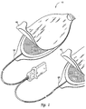
- FIG. 1 is a perspective view of an electrode pad system 10 which does not constitute an embodiment of this invention.
- the electrode pad system is comprised of two components; the first component being the electrode layer 20 and the second component being the releasing layer 40.
- the actual construction of the two components is shown in more detail in FIG. 2.
- An advantage of this two-part construction is that it streamlines the use of the electrode to two steps: deployment and attachment. Thus, the electrode is deployed with one motion prior to applying the electrode to the victim. This construction eliminates additional steps, such as opening the packaging and removing the electrodes prior to applying the electrodes to the victim.
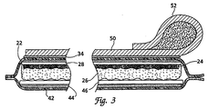
- FIG. 2 is an expanded cross-section of the electrode system 10 shown in FIG. 1.
- One side of each component ( 20, 40 ) forms a non-conductive outer sealing layer ( 22, 42 ).
- the outer sealing layer is a coated outer sealing layer formed from heat sealing material, such as polyethylene coated polyester or polyethylene coated foil.
- the electrode layer 20 is formed from the outer sealing layer 22 adhered to a non-conductive layer 28 with and adhesive layer 34 .
- An electrode disk 24 is adhered to the non-conductive layer of the outer sealing layer using an appropriate adhesive.
- the electrode disk 24 is formed of a suitable conductive material such as 2 mil tin and is attached to the interior surface of the outer sealing layer 22 with a suitable medical grade adhesive.
- the electrode disks are electrically connected to a lead wire 30 between the non-conductive sealing layer and the electrode disk on the upper surface of the electrode disk.
- the lower surface of the electrode disk is covered with a layer of conductive gel 26.
- a suitable conductive gel would be, for example, RG 63T hydrogel.
- the conductive gel has adhesive qualities that enable the gel to adhere to the skin of the victim.
- the electrode layer may be formed so that one end forms a pull tab 32 .
- the electrode is connected to the lead wire 30 which is connected to an electrode connector (shown in FIG. 1) or directly connected to the defibrillator.
- the lead wire 30 may be attached to a ring terminal prior to attaching to the electrode disk 24 .
- a washer may be provided between the ring terminal and the electrode disk 24 to improve the electrical connection.
- an insulating disk may be provided between the electrode disk 24 and the washer.
- the releasing layer 40 is formed from an outer sealing layer 42 which is adhered to a non-conductive layer 46 with the use of an appropriate adhesive 44 .
- the non-conductive layer is formed of a silicon coated polypropylene impregnated material.
- the releasing layer 40 is formed so that one end forms a pull tab 48 thus allowing the electrode conductive surface to be exposed with a single pulling motion.
- FIG. 3 is a cross-section of an embodiment of the electrode system 10 shown in FIG. 1.
- the electrode system includes a gripper 50 attached to the outer layer of the electrode layer 20 with the use of an appropriate adhesive.
- the gripper 50 enables the user to firmly grasp the electrode layer 20 while pulling the pull-tab 48 of the releasing layer.
- the gripper 50 is provided to improve the user's ability to quickly release the electrode layer 20 when deploying the electrode.
- the gripper 50 includes a cylindrical grip 52 formed integrally with a flattened section. The flattened side of the gripper 50 is adhered to the outer surface of the sealing layer 22 .
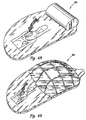
- FIGS. 4A-B shows an alternative embodiment of the electrode system 10 shown in FIGS. 1 and 3.
- the gripper 50 is comprised of a conformable layer 50, 60 that enables the user to firmly and easily grip the electrode layer 20 while removing the releasing layer 40.
- the conformable layer is formed of a suitably flexible material, such as medium density polyethylene foam.
- the conformable layer 50, 60 may also have grooves, or channels, along its length in at least one direction.
- the conformable layer may be formed from several smaller pieces of foam positioned so that a segmented conformable layer is formed.
- the conformable layer 60 is manufactured from a single piece of foam with grooves, or channels, along its length in two directions, as shown in FIG. 4B.
- the conformable layer 60 is flat on one side thus enabling the conformable layer 60 to adhere to the exterior surface of the sealing layer.
- the exposed surface of the conformable layer 60 is curved on one side so that it fits within the hand of the user.
- the conformable layer 60 also improves the user's ability to apply the electrode pad.
- the user holds the pull tab 28 of the electrode layer 20 in one hand while pulling on the pull tab 48 of the releasing layer 40 with the other hand.
- the hydrogel layer 26 is exposed and applied directly to the victim's chest. The actual site of electrode placement will depend upon the protocol followed by the user.
- the user grips the gripper 50 in one hand while pulling on the pull tab 48 of the releasing layer 40 with the other hand.
- the hydrogel layer 26 is exposed and applied directly to the victim's chest.
- the user grips the conformable layer 50, 60 in one hand while pulling on the pull tab 48 with the other hand. Again, upon pulling the two layers apart, the hydrogel layer 26 is exposed and applied directly to the victim's chest.
Description
Claims (8)
- An electrode system (10) comprising, in sealed combination,
an electrode layer (20);
a releasing layer (40) having a pull tab (48); and
a gripper (50) comprising a conformal layer (60; 80) having a first, flat surface by which it is adhered to said electrode layer (20) and a second exposed surface which is curved on one side to enable a user to grip the electrode layer (20) while detaching the releasing layer (40) using the pull tab (48). - An electrode system (10) as claimed in claim 1, wherein the gripper (50) is a conformable segmented layer (60).
- An electrode system (10} as claimed in claim 1 or claim 2, wherein the electrode layer (20) is further comprised of a hydrogel layer (26) and an electrode disk (24) adhered to a sealing layer (22).
- An electrode system (10) as claimed in claim 3, wherein the electrode disk is a 2 mil (0.05 mm) tin disk.
- An electrode system (10) as claimed in any preceding claim, wherein the releasing layer (40) is further comprised of a non-stick layer (46) adhered to an outer sealing layer (42).
- An electrode system (10) as claimed in any preceding claim, wherein the electrode layer (20) and the releasing layer (40) are hermetically sealed.
- A method of using an electrode system (10), the electrode system (10} being as claimed in any preceding claim, the method comprising:holding the pull tab (48) of the releasing layer (40) in one hand; andpulling the gripper (50; 60; 80) of the electrode layer (20) with the other hand to expose an electrode surface on the electrode layer (20).
- A method as claimed in claim 7, further comprising the step of applying the electrode to a patient's chest.
Applications Claiming Priority (2)
| Application Number | Priority Date | Filing Date | Title |
|---|---|---|---|
| US145168 | 1998-09-01 | ||
| US09/145,168 US6272385B1 (en) | 1998-09-01 | 1998-09-01 | Independently deployable sealed defibrillator electrode pad and method of use |
Publications (3)
| Publication Number | Publication Date |
|---|---|
| EP0983775A2 EP0983775A2 (en) | 2000-03-08 |
| EP0983775A3 EP0983775A3 (en) | 2000-12-06 |
| EP0983775B1 true EP0983775B1 (en) | 2005-06-01 |
Family
ID=22511897
Family Applications (1)
| Application Number | Title | Priority Date | Filing Date |
|---|---|---|---|
| EP99306528A Expired - Lifetime EP0983775B1 (en) | 1998-09-01 | 1999-08-19 | Independently deployable sealed defibrillator electrode pad and method of use |
Country Status (4)
| Country | Link |
|---|---|
| US (1) | US6272385B1 (en) |
| EP (1) | EP0983775B1 (en) |
| JP (2) | JP2000070381A (en) |
| DE (1) | DE69925550T2 (en) |
Families Citing this family (78)
| Publication number | Priority date | Publication date | Assignee | Title |
|---|---|---|---|---|
| AUPQ788400A0 (en) * | 2000-05-30 | 2000-06-22 | Wildon, Michael Peter | Epicardial stimulation lead |
| US6754528B2 (en) | 2001-11-21 | 2004-06-22 | Cameraon Health, Inc. | Apparatus and method of arrhythmia detection in a subcutaneous implantable cardioverter/defibrillator |
| US7069080B2 (en) | 2000-09-18 | 2006-06-27 | Cameron Health, Inc. | Active housing and subcutaneous electrode cardioversion/defibrillating system |
| US20020035381A1 (en) | 2000-09-18 | 2002-03-21 | Cameron Health, Inc. | Subcutaneous electrode with improved contact shape for transthoracic conduction |
| US6721597B1 (en) | 2000-09-18 | 2004-04-13 | Cameron Health, Inc. | Subcutaneous only implantable cardioverter defibrillator and optional pacer |
| US7146212B2 (en) | 2000-09-18 | 2006-12-05 | Cameron Health, Inc. | Anti-bradycardia pacing for a subcutaneous implantable cardioverter-defibrillator |
| US6874621B2 (en) * | 2001-02-27 | 2005-04-05 | Koninklijke Philips Electronics N.V. | Method and package for increasing electrode shelf life |
| US6560485B2 (en) | 2001-03-27 | 2003-05-06 | Koninklijke Philips Electronics N.V. | Four contact identification defibrillator electrode system |
| US7027877B2 (en) * | 2001-08-23 | 2006-04-11 | Zoll Medical Corporation | Method of applying defibrilator electrode pad with folded release sheet |
| US7069074B2 (en) | 2001-11-07 | 2006-06-27 | Medtronic Emergency Response Systems, Inc. | Easy-to-use electrode and package |
| US20040143301A1 (en) * | 2003-01-22 | 2004-07-22 | Christian Hunt | Skin electrodes with design thereon |
| US7187985B2 (en) * | 2003-07-18 | 2007-03-06 | 3M Innovative Properties Company | Biomedical electrode with current spreading layer |
| US7822488B2 (en) * | 2004-03-23 | 2010-10-26 | Koninklijke Philips Electronics N.V. | Self-storing medical electrodes |
| US7668604B2 (en) * | 2004-06-16 | 2010-02-23 | Conmed Corporation | Packaging for medical pads and electrodes |
| WO2006046160A1 (en) * | 2004-10-29 | 2006-05-04 | Koninklijke Philips Electronics, N.V. | Electrode and enclosure for cardiac monitoring and treatment |
| US20060142831A1 (en) * | 2004-12-28 | 2006-06-29 | Medtronic Emergency Response Systems, Inc. | Limited use ECG electrode set |
| US20070255380A1 (en) * | 2006-04-27 | 2007-11-01 | Peter Meyer | Electrode pad packaging systems and methods |
| US7869855B2 (en) * | 2006-09-28 | 2011-01-11 | Tyco Healthcare Group Lp | Medical apparatus with releasable applicator |
| US8676291B2 (en) | 2006-11-13 | 2014-03-18 | Koninklijke Philips N.V. | Halibut release liner for a defibrillator electrode pad |
| US20100059407A1 (en) * | 2007-01-15 | 2010-03-11 | John Curtis Kortman | Cover with circuit |
| US7816412B2 (en) * | 2007-02-23 | 2010-10-19 | Conmed Corporation | Electrically conductive hydrogels |
| RU2556969C2 (en) * | 2009-09-28 | 2015-07-20 | Конинклейке Филипс Электроникс Н.В. | Defibrillator with preliminarily connected electrode pads with reduced sensitivity to mistaken asystole identification |
| JP5697100B2 (en) | 2010-02-05 | 2015-04-08 | 国立大学法人秋田大学 | Solid electrolyte and electrochemical element |
| US9037477B2 (en) | 2010-10-08 | 2015-05-19 | Cardiac Science Corporation | Computer-implemented system and method for evaluating ambulatory electrocardiographic monitoring of cardiac rhythm disorders |
| US8239012B2 (en) | 2010-10-08 | 2012-08-07 | Cardiac Science Corporation | Microcontrolled electrocardiographic monitoring circuit with differential voltage encoding |
| US20120089000A1 (en) | 2010-10-08 | 2012-04-12 | Jon Mikalson Bishay | Ambulatory Electrocardiographic Monitor For Providing Ease Of Use In Women And Method Of Use |
| US8613708B2 (en) | 2010-10-08 | 2013-12-24 | Cardiac Science Corporation | Ambulatory electrocardiographic monitor with jumpered sensing electrode |
| US9881521B2 (en) * | 2011-01-17 | 2018-01-30 | Prestan Products Llc | Manikin sensing pads and liners in an AED training system |
| US8965533B2 (en) * | 2011-03-28 | 2015-02-24 | Koninklijke Philips N.V. | Defibrillator electrode pad with two peel tabs |
| WO2014070123A1 (en) * | 2012-11-01 | 2014-05-08 | Ulusahin Omer Sezgin | A protected electrode with enhanced body adhesion and insulation characteristics |
| US10279189B2 (en) | 2013-06-14 | 2019-05-07 | Cardiothrive, Inc. | Wearable multiphasic cardioverter defibrillator system and method |
| US9393402B2 (en) * | 2013-08-12 | 2016-07-19 | Physio-Control, Inc. | Electrode tray with integrated connector and storage for wires |
| US9619660B1 (en) | 2013-09-25 | 2017-04-11 | Bardy Diagnostics, Inc. | Computer-implemented system for secure physiological data collection and processing |
| US10463269B2 (en) | 2013-09-25 | 2019-11-05 | Bardy Diagnostics, Inc. | System and method for machine-learning-based atrial fibrillation detection |
| US9433380B1 (en) | 2013-09-25 | 2016-09-06 | Bardy Diagnostics, Inc. | Extended wear electrocardiography patch |
| US10736529B2 (en) | 2013-09-25 | 2020-08-11 | Bardy Diagnostics, Inc. | Subcutaneous insertable electrocardiography monitor |
| US9545204B2 (en) | 2013-09-25 | 2017-01-17 | Bardy Diagnostics, Inc. | Extended wear electrocardiography patch |
| US9700227B2 (en) | 2013-09-25 | 2017-07-11 | Bardy Diagnostics, Inc. | Ambulatory electrocardiography monitoring patch optimized for capturing low amplitude cardiac action potential propagation |
| US9408545B2 (en) | 2013-09-25 | 2016-08-09 | Bardy Diagnostics, Inc. | Method for efficiently encoding and compressing ECG data optimized for use in an ambulatory ECG monitor |
| US9615763B2 (en) | 2013-09-25 | 2017-04-11 | Bardy Diagnostics, Inc. | Ambulatory electrocardiography monitor recorder optimized for capturing low amplitude cardiac action potential propagation |
| US9433367B2 (en) | 2013-09-25 | 2016-09-06 | Bardy Diagnostics, Inc. | Remote interfacing of extended wear electrocardiography and physiological sensor monitor |
| US10251576B2 (en) | 2013-09-25 | 2019-04-09 | Bardy Diagnostics, Inc. | System and method for ECG data classification for use in facilitating diagnosis of cardiac rhythm disorders with the aid of a digital computer |
| US10165946B2 (en) | 2013-09-25 | 2019-01-01 | Bardy Diagnostics, Inc. | Computer-implemented system and method for providing a personal mobile device-triggered medical intervention |
| US10820801B2 (en) | 2013-09-25 | 2020-11-03 | Bardy Diagnostics, Inc. | Electrocardiography monitor configured for self-optimizing ECG data compression |
| US9655537B2 (en) | 2013-09-25 | 2017-05-23 | Bardy Diagnostics, Inc. | Wearable electrocardiography and physiology monitoring ensemble |
| US9364155B2 (en) | 2013-09-25 | 2016-06-14 | Bardy Diagnostics, Inc. | Self-contained personal air flow sensing monitor |
| US9408551B2 (en) | 2013-11-14 | 2016-08-09 | Bardy Diagnostics, Inc. | System and method for facilitating diagnosis of cardiac rhythm disorders with the aid of a digital computer |
| US10888239B2 (en) | 2013-09-25 | 2021-01-12 | Bardy Diagnostics, Inc. | Remote interfacing electrocardiography patch |
| US10806360B2 (en) | 2013-09-25 | 2020-10-20 | Bardy Diagnostics, Inc. | Extended wear ambulatory electrocardiography and physiological sensor monitor |
| US9345414B1 (en) | 2013-09-25 | 2016-05-24 | Bardy Diagnostics, Inc. | Method for providing dynamic gain over electrocardiographic data with the aid of a digital computer |
| US9655538B2 (en) | 2013-09-25 | 2017-05-23 | Bardy Diagnostics, Inc. | Self-authenticating electrocardiography monitoring circuit |
| US10667711B1 (en) | 2013-09-25 | 2020-06-02 | Bardy Diagnostics, Inc. | Contact-activated extended wear electrocardiography and physiological sensor monitor recorder |
| US10624551B2 (en) | 2013-09-25 | 2020-04-21 | Bardy Diagnostics, Inc. | Insertable cardiac monitor for use in performing long term electrocardiographic monitoring |
| US9775536B2 (en) | 2013-09-25 | 2017-10-03 | Bardy Diagnostics, Inc. | Method for constructing a stress-pliant physiological electrode assembly |
| US10799137B2 (en) | 2013-09-25 | 2020-10-13 | Bardy Diagnostics, Inc. | System and method for facilitating a cardiac rhythm disorder diagnosis with the aid of a digital computer |
| US11213237B2 (en) | 2013-09-25 | 2022-01-04 | Bardy Diagnostics, Inc. | System and method for secure cloud-based physiological data processing and delivery |
| US9504423B1 (en) | 2015-10-05 | 2016-11-29 | Bardy Diagnostics, Inc. | Method for addressing medical conditions through a wearable health monitor with the aid of a digital computer |
| US9717433B2 (en) | 2013-09-25 | 2017-08-01 | Bardy Diagnostics, Inc. | Ambulatory electrocardiography monitoring patch optimized for capturing low amplitude cardiac action potential propagation |
| WO2015048194A1 (en) | 2013-09-25 | 2015-04-02 | Bardy Diagnostics, Inc. | Self-contained personal air flow sensing monitor |
| US20190167139A1 (en) | 2017-12-05 | 2019-06-06 | Gust H. Bardy | Subcutaneous P-Wave Centric Insertable Cardiac Monitor For Long Term Electrocardiographic Monitoring |
| US9717432B2 (en) | 2013-09-25 | 2017-08-01 | Bardy Diagnostics, Inc. | Extended wear electrocardiography patch using interlaced wire electrodes |
| US10433751B2 (en) | 2013-09-25 | 2019-10-08 | Bardy Diagnostics, Inc. | System and method for facilitating a cardiac rhythm disorder diagnosis based on subcutaneous cardiac monitoring data |
| US10433748B2 (en) | 2013-09-25 | 2019-10-08 | Bardy Diagnostics, Inc. | Extended wear electrocardiography and physiological sensor monitor |
| US11723575B2 (en) | 2013-09-25 | 2023-08-15 | Bardy Diagnostics, Inc. | Electrocardiography patch |
| US9737224B2 (en) | 2013-09-25 | 2017-08-22 | Bardy Diagnostics, Inc. | Event alerting through actigraphy embedded within electrocardiographic data |
| US10736531B2 (en) | 2013-09-25 | 2020-08-11 | Bardy Diagnostics, Inc. | Subcutaneous insertable cardiac monitor optimized for long term, low amplitude electrocardiographic data collection |
| USD793566S1 (en) | 2015-09-10 | 2017-08-01 | Bardy Diagnostics, Inc. | Extended wear electrode patch |
| USD717955S1 (en) | 2013-11-07 | 2014-11-18 | Bardy Diagnostics, Inc. | Electrocardiography monitor |
| USD831833S1 (en) | 2013-11-07 | 2018-10-23 | Bardy Diagnostics, Inc. | Extended wear electrode patch |
| USD744659S1 (en) | 2013-11-07 | 2015-12-01 | Bardy Diagnostics, Inc. | Extended wear electrode patch |
| USD801528S1 (en) | 2013-11-07 | 2017-10-31 | Bardy Diagnostics, Inc. | Electrocardiography monitor |
| USD892340S1 (en) | 2013-11-07 | 2020-08-04 | Bardy Diagnostics, Inc. | Extended wear electrode patch |
| US10004894B2 (en) | 2014-11-19 | 2018-06-26 | Intermountain Intellectual Asset Management, Llc | Defibrillators with multi-pad electrodes and related methods |
| USD766447S1 (en) | 2015-09-10 | 2016-09-13 | Bardy Diagnostics, Inc. | Extended wear electrode patch |
| US11116451B2 (en) | 2019-07-03 | 2021-09-14 | Bardy Diagnostics, Inc. | Subcutaneous P-wave centric insertable cardiac monitor with energy harvesting capabilities |
| US11696681B2 (en) | 2019-07-03 | 2023-07-11 | Bardy Diagnostics Inc. | Configurable hardware platform for physiological monitoring of a living body |
| US11096579B2 (en) | 2019-07-03 | 2021-08-24 | Bardy Diagnostics, Inc. | System and method for remote ECG data streaming in real-time |
| USD985781S1 (en) * | 2020-08-19 | 2023-05-09 | Morari, Llc | Electrode stimulation applicator patch |
Family Cites Families (25)
| Publication number | Priority date | Publication date | Assignee | Title |
|---|---|---|---|---|
| CH636034A5 (en) | 1979-03-17 | 1983-05-13 | Maag Zahnraeder & Maschinen Ag | DRESSING DEVICE FOR A PLATE-SHAPED GRINDING WHEEL ON A TOOTHED FRAME GRINDING MACHINE. |
| US4895169A (en) | 1980-08-08 | 1990-01-23 | Darox Corporation | Disposable non-invasive stimulating electrode set |
| US4852585A (en) | 1980-08-08 | 1989-08-01 | Darox Corporation | Tin-stannous chloride electrode element |
| US4419998A (en) | 1980-08-08 | 1983-12-13 | R2 Corporation | Physiological electrode systems |
| US4653503A (en) | 1983-11-23 | 1987-03-31 | R2 Corporation | Physiological electrodes for use with magnetic connector |
| US4681112A (en) | 1985-01-08 | 1987-07-21 | Physio-Control Corporation | Medical instrument including electrodes adapted for right and left-handed use |
| US4779630A (en) * | 1987-09-18 | 1988-10-25 | Katecho, Inc. | Defibrillator pad assembly and method for using same |
| US4979517A (en) | 1988-02-01 | 1990-12-25 | Physio-Control Corporation | Disposable stimulation electrode with long shelf life and improved current density profile |
| US4955381A (en) | 1988-08-26 | 1990-09-11 | Cardiotronics, Inc. | Multi-pad, multi-function electrode |
| US5080099A (en) | 1988-08-26 | 1992-01-14 | Cardiotronics, Inc. | Multi-pad, multi-function electrode |
| US5150708A (en) * | 1990-12-03 | 1992-09-29 | Spacelabs, Inc. | Tabbed defibrillator electrode pad |
| US5137458A (en) | 1991-01-11 | 1992-08-11 | Physio-Control Corporation | Electrode placement training system |
| AU2377592A (en) | 1991-07-12 | 1993-02-11 | Ludlow Corporation | Biomedical electrode |
| DE4238263A1 (en) * | 1991-11-15 | 1993-05-19 | Minnesota Mining & Mfg | Adhesive comprising hydrogel and crosslinked polyvinyl:lactam - is used in electrodes for biomedical application providing low impedance and good mechanical properties when water and/or moisture is absorbed from skin |
| US5330526A (en) | 1992-05-01 | 1994-07-19 | Zmd Corporation | Combined defibrillation and pacing electrode |
| US5984102A (en) * | 1992-09-24 | 1999-11-16 | Survivalink Corporation | Medical electrode packaging technology |
| US5506059A (en) * | 1993-05-14 | 1996-04-09 | Minnesota Mining And Manufacturing Company | Metallic films and articles using same |
| US5466244A (en) | 1993-05-18 | 1995-11-14 | Heartstream, Inc. | Defibrillator electrode system |
| US5520683A (en) * | 1994-05-16 | 1996-05-28 | Physiometrix, Inc. | Medical electrode and method |
| US5456710A (en) * | 1994-06-30 | 1995-10-10 | Physio-Control Corporation | Vented electrode |
| US5571165A (en) | 1995-12-08 | 1996-11-05 | Ferrari; R. Keith | X-ray transmissive transcutaneous stimulating electrode |
| US5827184A (en) * | 1995-12-29 | 1998-10-27 | Minnesota Mining And Manufacturing Company | Self-packaging bioelectrodes |
| US6135953A (en) * | 1996-01-25 | 2000-10-24 | 3M Innovative Properties Company | Multi-functional biomedical electrodes |
| US5700281A (en) * | 1996-06-04 | 1997-12-23 | Survivalink Corporation | Stage and state monitoring automated external defibrillator |
| JPH1095962A (en) * | 1996-09-25 | 1998-04-14 | Nitto Denko Corp | Electroconductive adhesive composition, electroconductive pad obtained from the same composition and medical electrode using the same |
-
1998
- 1998-09-01 US US09/145,168 patent/US6272385B1/en not_active Expired - Lifetime
-
1999
- 1999-08-19 DE DE69925550T patent/DE69925550T2/en not_active Expired - Lifetime
- 1999-08-19 EP EP99306528A patent/EP0983775B1/en not_active Expired - Lifetime
- 1999-08-25 JP JP11238153A patent/JP2000070381A/en active Pending
-
2008
- 2008-01-28 JP JP2008016026A patent/JP2008110242A/en active Pending
Also Published As
| Publication number | Publication date |
|---|---|
| EP0983775A2 (en) | 2000-03-08 |
| EP0983775A3 (en) | 2000-12-06 |
| DE69925550D1 (en) | 2005-07-07 |
| US6272385B1 (en) | 2001-08-07 |
| DE69925550T2 (en) | 2006-04-27 |
| JP2000070381A (en) | 2000-03-07 |
| JP2008110242A (en) | 2008-05-15 |
Similar Documents
| Publication | Publication Date | Title |
|---|---|---|
| EP0983775B1 (en) | Independently deployable sealed defibrillator electrode pad and method of use | |
| US5466244A (en) | Defibrillator electrode system | |
| US6178357B1 (en) | Electrode pad system and defibrillator electrode pad that reduces the risk of peripheral shock | |
| US5951598A (en) | Electrode system | |
| US6115638A (en) | Medical electrode with conductive release liner | |
| EP1827572B1 (en) | Electrode and enclosure for cardiac monitoring and treatment | |
| RU2585731C2 (en) | Defibrillator electrode patch with two laminate tabs | |
| EP1729847B1 (en) | Self-storing medical electrodes | |
| JP5430832B2 (en) | Medical electrode | |
| US6993395B2 (en) | Skin-applied electrode pads | |
| US7027877B2 (en) | Method of applying defibrilator electrode pad with folded release sheet | |
| JPS63229070A (en) | Electrode for cardiac defibrillation, and its production and cardiac defibrillation method | |
| JP5647550B2 (en) | Electrode delivery system | |
| US11433249B1 (en) | Compact AED with one distal electrode | |
| US4899754A (en) | Flat, conformable, biomedical electrode allowing removal of electrical lead wire | |
| US6714824B1 (en) | Universal electrode system and methods of use and manufacture | |
| NL8120191A (en) | METHOD AND APPARATUS FOR IMPLANTING A CARTRIDGE | |
| JP4032136B2 (en) | Biological electrode and method for producing the same | |
| JP5128202B2 (en) | Medical electrode | |
| EP1412019A2 (en) | Hands-free paddles using single-use adhesive pads |
Legal Events
| Date | Code | Title | Description |
|---|---|---|---|
| PUAI | Public reference made under article 153(3) epc to a published international application that has entered the european phase |
Free format text: ORIGINAL CODE: 0009012 |
|
| AK | Designated contracting states |
Kind code of ref document: A2 Designated state(s): DE GB |
|
| AX | Request for extension of the european patent |
Free format text: AL;LT;LV;MK;RO;SI |
|
| PUAL | Search report despatched |
Free format text: ORIGINAL CODE: 0009013 |
|
| AK | Designated contracting states |
Kind code of ref document: A3 Designated state(s): AT BE CH CY DE DK ES FI FR GB GR IE IT LI LU MC NL PT SE |
|
| AX | Request for extension of the european patent |
Free format text: AL;LT;LV;MK;RO;SI |
|
| RAP1 | Party data changed (applicant data changed or rights of an application transferred) |
Owner name: AGILENT TECHNOLOGIES INC |
|
| 17P | Request for examination filed |
Effective date: 20010515 |
|
| RAP1 | Party data changed (applicant data changed or rights of an application transferred) |
Owner name: AGILENT TECHNOLOGIES INC. |
|
| RAP1 | Party data changed (applicant data changed or rights of an application transferred) |
Owner name: AGILENT TECHNOLOGIES INC. A DELAWARE CORPORATION |
|
| AKX | Designation fees paid |
Free format text: DE GB |
|
| RAP1 | Party data changed (applicant data changed or rights of an application transferred) |
Owner name: AGILENT TECHNOLOGIES, INC. (A DELAWARE CORPORATION |
|
| 17Q | First examination report despatched |
Effective date: 20030603 |
|
| RAP1 | Party data changed (applicant data changed or rights of an application transferred) |
Owner name: KONINKLIJKE PHILIPS ELECTRONICS N.V. |
|
| GRAP | Despatch of communication of intention to grant a patent |
Free format text: ORIGINAL CODE: EPIDOSNIGR1 |
|
| GRAS | Grant fee paid |
Free format text: ORIGINAL CODE: EPIDOSNIGR3 |
|
| GRAA | (expected) grant |
Free format text: ORIGINAL CODE: 0009210 |
|
| AK | Designated contracting states |
Kind code of ref document: B1 Designated state(s): DE GB |
|
| REG | Reference to a national code |
Ref country code: GB Ref legal event code: FG4D |
|
| REF | Corresponds to: |
Ref document number: 69925550 Country of ref document: DE Date of ref document: 20050707 Kind code of ref document: P |
|
| PLBE | No opposition filed within time limit |
Free format text: ORIGINAL CODE: 0009261 |
|
| STAA | Information on the status of an ep patent application or granted ep patent |
Free format text: STATUS: NO OPPOSITION FILED WITHIN TIME LIMIT |
|
| 26N | No opposition filed |
Effective date: 20060302 |
|
| REG | Reference to a national code |
Ref country code: DE Ref legal event code: R082 Ref document number: 69925550 Country of ref document: DE Representative=s name: MEISSNER, BOLTE & PARTNER GBR, DE |
|
| REG | Reference to a national code |
Ref country code: DE Ref legal event code: R082 Ref document number: 69925550 Country of ref document: DE Representative=s name: MEISSNER BOLTE PATENTANWAELTE RECHTSANWAELTE P, DE Effective date: 20140328 Ref country code: DE Ref legal event code: R082 Ref document number: 69925550 Country of ref document: DE Representative=s name: MEISSNER, BOLTE & PARTNER GBR, DE Effective date: 20140328 Ref country code: DE Ref legal event code: R081 Ref document number: 69925550 Country of ref document: DE Owner name: KONINKLIJKE PHILIPS N.V., NL Free format text: FORMER OWNER: KONINKLIJKE PHILIPS ELECTRONICS N.V., EINDHOVEN, NL Effective date: 20140328 |
|
| PGFP | Annual fee paid to national office [announced via postgrant information from national office to epo] |
Ref country code: GB Payment date: 20180831 Year of fee payment: 20 |
|
| PGFP | Annual fee paid to national office [announced via postgrant information from national office to epo] |
Ref country code: DE Payment date: 20181031 Year of fee payment: 20 |
|
| REG | Reference to a national code |
Ref country code: DE Ref legal event code: R071 Ref document number: 69925550 Country of ref document: DE |
|
| REG | Reference to a national code |
Ref country code: GB Ref legal event code: PE20 Expiry date: 20190818 |
|
| PG25 | Lapsed in a contracting state [announced via postgrant information from national office to epo] |
Ref country code: GB Free format text: LAPSE BECAUSE OF EXPIRATION OF PROTECTION Effective date: 20190818 |