EP0983618B1 - Safety device at connectors to electric current rails, installation channels and the like - Google Patents
Safety device at connectors to electric current rails, installation channels and the like Download PDFInfo
- Publication number
- EP0983618B1 EP0983618B1 EP98923291A EP98923291A EP0983618B1 EP 0983618 B1 EP0983618 B1 EP 0983618B1 EP 98923291 A EP98923291 A EP 98923291A EP 98923291 A EP98923291 A EP 98923291A EP 0983618 B1 EP0983618 B1 EP 0983618B1
- Authority
- EP
- European Patent Office
- Prior art keywords
- blocking
- rail
- list
- designed
- connector
- Prior art date
- Legal status (The legal status is an assumption and is not a legal conclusion. Google has not performed a legal analysis and makes no representation as to the accuracy of the status listed.)
- Expired - Lifetime
Links
- 238000009434 installation Methods 0.000 title description 2
- 230000000903 blocking effect Effects 0.000 claims description 80
- 230000007246 mechanism Effects 0.000 claims description 41
- 210000002105 tongue Anatomy 0.000 claims description 37
- 238000003780 insertion Methods 0.000 claims description 28
- 230000037431 insertion Effects 0.000 claims description 28
- 210000000078 claw Anatomy 0.000 claims description 8
- 238000005452 bending Methods 0.000 claims description 6
- 238000006073 displacement reaction Methods 0.000 claims description 5
- 230000009471 action Effects 0.000 claims description 4
- 230000004913 activation Effects 0.000 claims description 4
- 239000000463 material Substances 0.000 claims description 4
- 230000008719 thickening Effects 0.000 claims description 3
- 239000011324 bead Substances 0.000 claims description 2
- 230000006835 compression Effects 0.000 claims description 2
- 238000007906 compression Methods 0.000 claims description 2
- 239000002184 metal Substances 0.000 claims description 2
- 239000004020 conductor Substances 0.000 description 7
- 239000011796 hollow space material Substances 0.000 description 5
- 238000002347 injection Methods 0.000 description 2
- 239000007924 injection Substances 0.000 description 2
- 230000002028 premature Effects 0.000 description 2
- 230000005540 biological transmission Effects 0.000 description 1
- 230000007797 corrosion Effects 0.000 description 1
- 238000005260 corrosion Methods 0.000 description 1
- 238000005286 illumination Methods 0.000 description 1
- 238000004519 manufacturing process Methods 0.000 description 1
- KRTSDMXIXPKRQR-AATRIKPKSA-N monocrotophos Chemical compound CNC(=O)\C=C(/C)OP(=O)(OC)OC KRTSDMXIXPKRQR-AATRIKPKSA-N 0.000 description 1
- 238000010422 painting Methods 0.000 description 1
- 239000000047 product Substances 0.000 description 1
- 230000001681 protective effect Effects 0.000 description 1
- 239000013589 supplement Substances 0.000 description 1
- 239000000725 suspension Substances 0.000 description 1
Images





Classifications
-
- H—ELECTRICITY
- H01—ELECTRIC ELEMENTS
- H01R—ELECTRICALLY-CONDUCTIVE CONNECTIONS; STRUCTURAL ASSOCIATIONS OF A PLURALITY OF MUTUALLY-INSULATED ELECTRICAL CONNECTING ELEMENTS; COUPLING DEVICES; CURRENT COLLECTORS
- H01R25/00—Coupling parts adapted for simultaneous co-operation with two or more identical counterparts, e.g. for distributing energy to two or more circuits
- H01R25/14—Rails or bus-bars constructed so that the counterparts can be connected thereto at any point along their length
- H01R25/142—Their counterparts
-
- H—ELECTRICITY
- H01—ELECTRIC ELEMENTS
- H01R—ELECTRICALLY-CONDUCTIVE CONNECTIONS; STRUCTURAL ASSOCIATIONS OF A PLURALITY OF MUTUALLY-INSULATED ELECTRICAL CONNECTING ELEMENTS; COUPLING DEVICES; CURRENT COLLECTORS
- H01R13/00—Details of coupling devices of the kinds covered by groups H01R12/70 or H01R24/00 - H01R33/00
- H01R13/44—Means for preventing access to live contacts
-
- H—ELECTRICITY
- H01—ELECTRIC ELEMENTS
- H01R—ELECTRICALLY-CONDUCTIVE CONNECTIONS; STRUCTURAL ASSOCIATIONS OF A PLURALITY OF MUTUALLY-INSULATED ELECTRICAL CONNECTING ELEMENTS; COUPLING DEVICES; CURRENT COLLECTORS
- H01R13/00—Details of coupling devices of the kinds covered by groups H01R12/70 or H01R24/00 - H01R33/00
- H01R13/44—Means for preventing access to live contacts
- H01R13/447—Shutter or cover plate
Definitions
- the present invention relates to a safety device of the type set forth in detail in the preamble of claim 1.
- the invention originates first of all from a connector device according to our Swedish patent application no. 9501690-3. It is true, that this connector device on the whole is advantageous, but it does not comprise any special means, which prevent a contact closure between the device and possible connections in it to power-consumption, when the connection bar of the device with connection pins has been inserted into an electric contact position in a current rail or the like , but before the device has been mechanically fastened in the rail.
- Such a premature concact position may of course result in damages to the contact devices, e.g. in the form of weld, burn and corrosion damages , but it can also result in risks for children and young people.
- DE-A-2 358 895 relates to a connector device for eletric current adjacent a floor list.
- This device does not even meet fundamental safety requirements , since the conductors in the current rail are freely accessible. Thus, e.g. a needle, a knife , a screw driver or the like can be directly put into the conductors.
- the cirrent carrying bushings in the connector device have been provided with a rotatable blocking disc, which can be rotated to a connection or a release position , provided two hooks positioned adjacent each other have been fastened around the floor list. These hooks are the only fastening device of the connector device and an external means, which can be easily damaged, e.g.
- the device when the device is installed and when it is removed. In the latter case it is possible, that the device can be torn away by bending the hooks upwards. There are no means to guide the device into the current rail and the risk , that the device will be turned the wrong way and that the contact pins will end up in a wrong conductor of course seems to be substantial. Since the device is square, there in only place available for a single connector . The device is mechanically seen constructed in such a way, that it is hardly possible to make room for more then one connector or the like.
- One object of the present invention is to in an efficient and internal way fasten such a device to a current rail and to automaticly prevent a premature contact position, in such a way, that it is only possible to draw electric current from a connector device, which is completely mechanically secured in the current rail. It must either be possible to mount and remove respectively a connector device, to which power-consumption devices have been connected.
- the guidance of the connector device into the current rail must be simple, quick and reliable. For the rest, the device must meet high safety reauirements, Also, the device must allow an arbitrary amount of connectors or the like to be mounted and allow substantial variations. Finally, these obejcts must be met in a simple way, which does not require considerable costs, when the device is either manufactured, mounted or used.
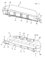
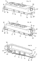
- the device according to the invention is in its entirety denoted by 1 in Figs. 1-14.
- a current rail 2 is also used and a connector 3 inserted into the current rail.
- the current rail which also can be an installation channel or the like and designed with two grooves for electric conductors, used for signal and communication transmissions, as well as said connector can of course be designed in an arbitrary way, to the extent, that this does not directly influence the present invention.
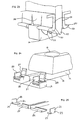
- the current rail has a body 4 with a longitudinal hollow space 5, a rear wall 6, designed e.g. for suspension of paintings or the like and at the bottom in profile shaped as a hook, on the inner side of which wall a ground rail 7 is mounted, and a front wall 8, in which a longitudinal lead-in hole 9 for an insertion part 10 of connector 3 has been made and behind which electric conductors 11 and 12 on each side of hole 9 are mounted.
- insertion part 10 of the preferably oblong connector 3 provided with several electric sockets 13, has a beam 14, which fills said hole 9 and on the free end of which , which abuts ground rail 7 , is mouned an e.g. longitudinal ground sheet 15 and with this connected ground clamps 17, which enclose the beam with their legs in e.g. recesses 16.
- an extension 18 protrudes in the axial direction, having the same width but a considerably smaller height.
- the free end of extension 18 supports a transverse contact bar 19 with electric contact pins 20,21 , which protrude in a direct way from ground sheet 15.
- Ground sheet 15 suitably protrudes somewhat beyond the bar with a slight bending downwards, away from said extension and the bar but is then bent upwards as a terminating rounding 22. Since this ground sheet portion is bent away in this manner, it is resilient and consequently secures a permanent conctact pressure.
- the embodiment according to Figs. 24 and 25 comprises adjustable and interchangeable respectively contact pins, e.g. removable to various positions along bar 19, which pins e.g. are L-shaped, the shoulder of the protruding leg, forming the pin, being provided with cuts 23 and 24 respectively, designed to guide the pins along rails 25 and 26 respectively, which are mounted in the bar and extend in its longitudinal direction and have a C-profile and receive the base leg of the L-profiles in a gliding condition.
- the controlled pin position is secured by means of pivoted lock clamps 27 and 28 respectively, through which bridges are connected to the body shell of the bar and are stopped with their free end in a position on the same adjacent the conctact pins by means of snap-in means known per se.
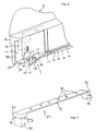
- this device comprises a blocking mechanism 29, which is shown in detail in Fig. 4. It preferably is an injection molded product with a flat list 31 provided with holes 30, which in a connection release position corresponds to the holes in the connectors.
- List 31 is provided with a front thickening 32, which extends downwards as well as forwards and is used, generally or together with the base, as a retaining means for the list in a guide opening 33 in the device and with an axial blocking means 34, which protrudes from the device and is designed to counteract an insertion of the device in rail 2 in said connection release position.
- a front thickening 32 which extends downwards as well as forwards and is used, generally or together with the base, as a retaining means for the list in a guide opening 33 in the device and with an axial blocking means 34, which protrudes from the device and is designed to counteract an insertion of the device in rail 2 in said connection release position.
- a front thickening 32 which extends downwards as well as forwards and is used, generally or together with the base, as a retaining means for the list in a guide opening 33 in the device and with an axial blocking means 34, which protrudes from the device and is designed to counteract an insertion of the device in rail 2 in
- blocking mechanism 29 there is also a slide, thickening or the like 37, which extends downwards as well as rearwards and has a multiple function.
- an insertion limiting mechanism in the form av e.g. a plate 38 having a flange 39 all around as an abutment against guide opening 33 or any other opening or any other recess in e.g. beam 14.
- a push button-like , axially backwardly extended protrusion 40 can be used, which in the inserted position of the blocking mechanism is flush with the contour of the rear end of the device (see Figs. 8 and 9).
- Recess 42 is designed for rear end 47 of ground sheet 15. Within this area the ground sheet, which mainly below beam 14 abuts the same, is bent obliquely downwards and backwards and then straight or somewhat obliquely rearwardly extended upwards through an opening 48 in the bottom side of the beam and finally horizontally backwards in the shape of a holding tongue 49. In its by the ground sheet not influenced condition the holding tongue is positioned at a level below the lower limitation of recess 42.
- a blocking mechanism according to Fig. 11 can normally not be used, since the holding tongue of the device, which is inserted into the rail, prevents an insertion of the blocking mechanism. Also in this way an extra safety and reliability factor is obatined when using the device according to the invention, which factor in its entirety has the following features:
- FIG. 1-7 Device (connector) 3 according to Figs. 1-7 has a rearwardly protruding blocking mechanism, which prevents the use of the connectors (see Fig. 6).
- This device can now be inserted into rail 2, as is shown in principle in Fig. 11, and be rotated as well as be swung into its contact position, which is shown in principle in Figs. 19 and 20, when the holding tongue firstly is lifted in order to release the insertion passage for the blocking mechanism and secondly, when appropriate, is supported by the lower limitation of recess 42, which does not necessarily have to be the case.
- the holding tongue can also be present somewhere in recess 42.
- the blocking mechanism is to be drawn backwards, possibly simply by pressing inwards blocking protrusion 34. Stop tongues 43,44 will be simultaneously drawn inwards and the holding tongue will slide downwards and out of recess 42, the spring force of the ground sheet and/or the stop tongues facilitating and speeding up a lifting of this connector portion out of the current rail. After the described swinging and rotation movements of the connector it can be removed completely from the current rail in order to e.g. place it in another position along the current rail.
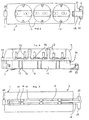
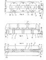
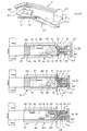
- Device 1' according to Figs. 15-23 is different from the device according to Figs. 1-14, since device 1' first of all comprises a list 31' , which is positioned on top of the connector and has holes 30'.
- the list covers the width and the length of the connector with the exception of a short piece, which is required for displacement movements between a blocking position and a release position.
- List 31' is guided by means of laterally disposed grooves 50 in its bottom side on shape-attached claw-like guide beads 51, turned away from each other, along the upper lateral edges of the connector or at least along their ends.
- the diameter of holes 30' correspond to the diameter of connectors 13.
- the front end of list 31' and/or its front sides can be provided with not shown insertion blocking means having the same function as the already described blocking means 34.
- a blocking mechanism 29' is guided in a vertical guide groove 33' .
- This mechanism comprises a slide 52, at the upper end of which a push button 40' is mounted, having a horizontal axially forwardly extended continuation retaining portion 53, which is mounted in a vertical groove 54, which extends through the rear part of the connector, and ends with its upper end flush with and above respectively the upper side of the connector, depending on the adjusted position.
- the retaining portion has such a length, that it in its retaining position abuts from behand the rear end of list 31' (Fig. 15).
- the lower end of the slide is at its rearmost part a point 55 and attached to the same towards a transverse arm 56 witih obliquely upwardly and outwardly towards both sides directed guiding holes 57 for tongues 58, downwardly extending from the bottom side of the connector.
- a mirror-symmetrical continuation of parts 53-55 can be used, forwards and attached to the transverse arm.
- the tongues are limited forwards and backwards by walls 59, which are directed downwards from the connector and which terminate in laterally extended stop claws 60.
- This device functions in the following way: In its release position according to Fig. 15, which also is its connection blocking position , the connector can be inserted in a current rail, be rotated a quarter of a revolution and be swung a quarter of a revolution in it , a connecting position according to Fig. 19 being obtained, in which an electric contact is established , but the connectors are still blocked up.
- Push button 40' is now pressed downwards to a position according to Fig.
- injection molded unit in which the tongue and the walls are connected to each other and can be swung as a unit around thinly designed shoulders at body 61 towards the blocking mechanism, which possibly can be integrated with the body of the connector.
- the thin shoulders will function as hinges or bridges.
- the blocking mechanism when it has been pushed upwards completely, will lock the list in its advanced connection blocking position and now the connector can be swung and rotated in the described way in order to remove it from the rail.
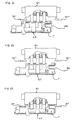
- a current rail 2 with connectors 3 which include safety devices 1".
- the current rail has a body 4 with a longitudinal hollow space 5, a rear wall 6, on the inner side of which a ground rail 7 is mounted, and a front wall 8, in which there is a longitudinal opening 9 for a lead-in portion 10" of the connector 3 " and behind which electric conductors 11 and 12 are mounted on each side of opening 9.
- Connector device 3" comprises a low or bottom portion 63 and a top portion 64.
- the purpose of such a dividing up is to create opportunities for varying output possibilities, the bottom portion always being designed in the same way, whereas the top portion can obtain a varying shape and functioning, e.g. in order to span joints and angles between adjacent current rails and in particular for varying remote terminals, which via cables 65 can lead to electric connectors 13" or illumination devices and the like.
- this dividing up which results in important production and handling advantages, it has nevertheless been considered, that safety will be obtained during work, i.e. subsequent to the attachment of the bottom portion in a current rail but before the top portion has been attached to the bottom portion.
- safety device 1 is similar to the device, which has been shown and described in connection with Figs. 1-14.
- the main difference is, that parts 37-42, 29-31 and 32,34 respectively, which according to Figs. 1-14 form a homogenous blocking mechanism , in this case have been divided up into three different means, namely a bottom portion 63, a list 31" movably mounted on it as well as a top portion 64.
- the bottom portion is not provided with blocking means 34, which instead is mounted on top portion 64 as means 34" and can be, in a simple and quick way, inserted into the current rail in the above described and shown way, its movable parts being disposed according to Fig. 28. It is shown, that from rear plate 38" two lateral claws 67 extend forwards having protrusions 68 turned towards each other, which in the shown insertion position are supported by primary recesses 69 in the sides of beam 14". The recesses diverge with their bottoms towards the insertion end of the connector and then reach secondary recesses 70.
- Block 41" is as in the previous case guided in beam 14" and ends at the end turned away from plate 38" in two diverging branches, which are designed as stop tongues 43" and 44".
- the tongues are made of a plastic material, e.g. a ABS-material, they can be bent away elasticly during a large bending, when the block is pushed further into beam 14", which is shown in Figs. 29 and 30, in which tongues 43", 44" have been forced out through openings 45" and consequently laterally protrude a short distance from beam 14" and constitute efficient retaining means, since they become hooked up behind front wall 8 after the insertion of the connector in the current rail.
- a plastic material e.g. a ABS-material
- claws 67 with protrusions 68 are pushed further into and onto the beam , protrusions 68 being removed from recesses 69 to recesses 70 against the action of the diverging passage between the two recesses.
- the claws which have been made in one piece jointly with plate 38" , block 41 " and tongues 43 “,44” ,are elasticly resilient first of all outwards and then inwards again in order to retain blocking mechanism 29" in either one of the positions.
- list 31" which with its two longitudinal edges is guided in the longitudinal direction on beam 14", e.g. in grooves 66 in mutually parallel elevations 71 on the beam, is positioned according to Figs. 29 and 35 respectively, in which position its openings 30", which suitably have an oblong slot-shape, are not congruent with connector holes 36" in the beam, a direct available electric contact thus not being allowed to be established.
- This protective position for the list is secured by means of a compression spring 72, which is mounted in a recess in the upper side of beam 14" and is grasped all around at one end of a follower arm 73, which protrudes downwards from list 31".
- upper portion 64 with its contact pins 35" will be pusshd into openings 30" in order to longitudinally remove the upper portion jointly with the list into a position according to Figs. 30 and 36 respectively, until pins 35" ,openings 30" and contact cases 36" are congruent, the pins thus being allowed to be completely pushed into the latter and lock the list in this contact position against the action of spring 72.
- the contact pins are laterally protected by means of exterior, downwardly protruding shell portions 74, which in their end positions end up in front of elevations 71.
- snap-in arms 32 which have been cut out of said shell portions 74 and reaches a point below the latter, with projections 75 facing each other on the interior side of the lower ends of the arms, will mesh with cavities 76 in the end surfaces of beam 14" in order to lock the top portion to the bottom portion.
- the projections blocking means 34" are disposed on the exterior side of the arms, which means penetrate hole 9 in the current rail in order to lock and stabilize the connection in the current rail. Also in this case the blocking means prevents, that somebody inadvertently join the top portion with the bottom portion and tries to insert the connectors, joined in this way into a current rail.
- a connector In case then a connector is to be removed from the current rail, it is necessary to first remove the top portion from the latter portion, which is done be inserting e.g. a screw driver into a hole 77 in each blocking means and bending it in order to make the projection leave the respective cavity, and then to lift off the top portion, the list, thanks to the spring, returning to the position according to Figs. 28/29 and 35 respectively. Then a screw driver or the like is applied between blocking mechanism 29" and beam 14" in a suitable place, possibly provided with special , for this purpose arranged location notches (not shown) , making it possible for protrusions 68 to leave recesses 70 and return to recesses 69. Tongues 43", 44" are in this way drawn into openings 45" and the bottom portion can be swung outwards out of the current rail in the way described and shown above.
- Fig. 26 it is also shown , that two bottom portions can be used to establish an electric connection between two adjacent current rails, an electric cable 65 extending between two top portions, adjacent their ends, in the respective current rails. Also, it is possible to use solely one top portion shell 74 in order to shield selected open sections of a current rail. The ends can be closed by means of end pieces 78.
Landscapes
- Connector Housings Or Holding Contact Members (AREA)
- Details Of Connecting Devices For Male And Female Coupling (AREA)
Description
Claims (15)
- A safety device (1;1';1") with a connection device (3;3';3") provided with connector openings (13;13';30;30';30'';36;36'') and connectors respectively for an electric current to an electric current rail (2) or the like, the connection device, which with a front end can be inserted into the current rail, being positioned by means of first locking means (19), which brings about an electric contact closure between the rail and said connection device and is positioned at this connector device end, second locking means at the rear end of the safety device being designed to lock the connection device, when it has been completely inserted into the rail, to the same, characterized in that blocking mechanisms (29;29';29") are provided to block up the connectors and the connector openings respectively against connection to contact pins or other electric devices (35;35") , until said second locking means has been activated and lock the connection device, which has been completely inserted into the rail, in relation to the rail by means of tongues (43;44;43';44';43";44"), which are positioned inside the insertion opening of the rail and behind its front wall (8) and which laterally protrude from the safety device, at the same time bringing about an automatic availability of the connectors and the connector openings respectively, which blocking mechanisms comprise a slide (37,41,52), disposed at the rear end of the safety device and designed to activate and inactivate respectively said second locking means, in that a removal of the connector device will imply first a removal of all possible power consumption connections from the connector device, and then a displacement of said second locking means to an inactive position, results in an automatic activation of said blocking mechanisms which also are designed to via the second locking means stop an insertion of at least the one end of the connector device into the rail when activated, in that at the rear end of the connection device (3;3';3") the main portion of the safety device (1;1';1") is disposed , which comprises said blocking mechanisms (29;29';29" ), which comprises a flat list (31;31';31"), provided with said openings (30;30';30" ), the openings in a connecting release position covering the holes (36;36") in the connectors.
- The devices according to claim 1, characterized in that the end of the device (3;3';3"), which end is the front axial one as regards the insertion of the device in the rail, is provided with blocking means (34), which protrude axially from the device and stops an insertion of the device in the rail in said connector release position, particularly because the list (31) or another connection device portion (64) is provided with a front thickening (32), which extends downwards as well as forwards and functions generally or jointly with the base as a blocking means for the list in a guide opening (33) in the device.
- The devices according to claim 1 or 2, characterized in that said slide or the like (37) is displaceable in a vertical direction or in a horizontal direction between a locking position and a release position and has a multiple function, including an insertion limitation preferably in the form of a plate (38) having a flange (39) all around designed to abut the guide opening (33) or another opening or another recess in e.g. the beam (14) and having a push button-like, axially backwardly directed protrusion (40).
- The devices according to claims 3, characterized in that below the protrusion (40) and axially seen in front of the plate (38) an L-shaped block (41) is disposed having a recess (42) between the two legs and the push button, disposed above, and its continuation axially inwards into the device respectively, in that from the area at the two free vertical comer edges of the lower leg two stop tongues (43,44) protrude, horizontally obliquely outwards and forwards, which suitably are made of metal and have resilience properties and which are fastened to the lower leg, and in that the free ends of the tongues always are guided by openings (45,46) in the lateral walls of the beam.
- The devices according to claim 4, characterized in that the recess (42) is designed for the rear end (47) of the ground sheet (15), within which area the ground sheet, which mainly below the beam (14) abuts the same, is bent obliquely downwards and backwards and then straight or somewhat backwardy directed upwards through an opening (48) in the bottom side of the beam and finally horizontally backwards in the shape of a tongue (49), in that in a not influenced condition of the ground sheet the stop tongue is designed to be positioned on a level below the lower limitation of the recess (42), and in that when the rear part of the beam (14) with the ground sheet is forced to abut the ground rail (7), the obliquely downwardy directed portion of the ground sheet is forced towards the bottom side of the beam, the stop tongue finally ending up on a level above said lower limitation of the recess (42), when the blocking mechanism can be pushed towards and the latter below the stop tongue, which now can exercise a retaining action on the blocking mechanism in this inserted position due to either friction or a certain profiling, e.g. because the outermost free end of the stop tongue meshes with an indent or the like in said limitation.
- The devices according to claim 1, characterized in that it comprises a list (31'), disposed above the device (3') and having holes (30') , which correspond to the diameter of the connectors (13') , which list covers the width and the length of the device, with the exception of a short piece designed for displacement movements between a blocking and a release position, in that the list (31') is guided by means of e.g. lateral grooves in its bottom side on shape-attached claw-like guide beads (51), which face each other, along the upper lateral edges of the device or at least along their ends, and in that the front end of the list and/or its front sides preferably are provided with insertion blocking means for the device.
- The devices according to claim 1 or 6, characterized in that in the rear end of the connector device(3') a blocking mechanism (29') is guided in a vertical guiding groove (33'), which mechanism comprises a slide (52), at the upper end of which a push button (40') is disposed having a horizontal axially forwardly directed blocking portion (53), which is mounted in a vertical groove (54), which extends through the device and ends with its upper end flush with and above respectively the upper side of the device, depending on the adjusted position and in that the blocking portion is so long, that it in its blocking position from behind abuts the rear end of the list (31').
- The devices according to claim 7, characterized in that the lower end of the slide (52) at the rear end is a point (55) and in connection with the same a transverse arm (56) towards with obliquely upwards and outwards to both sides directed forced guidance spaces (57) for tongues (58), which protrude downwards from the bottom side of the device, in that preferably in connection with the transverse arm forwards a mirror-symmetrical repetition of the blocking portion (53) and the point (55) is disposed and in that said tongues (58) are forwardly and backwardly limited by walls (59), extending downwards from the device, which end in laterally extending holding claws (60).
- The devices according to claims 6-8, characterized in that the connector device (3') is designed, in the connection blocking position of the list (31'), to be completely inserted into the rail (2), the electric contact position being established, in that the blocking portion (53) by means of the push button (40') then is designed to be pushed downwards, directed into the rail, while said point (55) is inserted between the walls (59), which initially are V-shaped and directed with their lower ends against each other, and the walls are taken apart, the claws (60) being introduced beind the inner ends or edges of the walls around the insertion opening (9) of the rail and a retaining of the rear end of the device in relation to the rail being accomplished.
- The devices according to claim 1, characterized in that the connector device (3") comprises a bottom or base portion (63) and a top portion (64) in order to with only one base portion form create opportunities for varying withdrawal possibilities, since different top portions with varying shapes and functions are available, particularly descigned to span joints and angles between adjacent current rails (2), for cabel-connected connectors (13") as well as for lighting devices and the like, the base portion (63) being designed to, without a top portion (64), be attached to and be removed from respectively a current rail (2) and the base portion, without an applied top portion, preferably being electricly secured or isolated outwards.
- The devices according to claim 10, characterized in that the blocking mechanism (37" - 42" ; 29" - 31" ; 32" ; 34") is divided into three different elements, namely the base portion (63), a list (31") disposed on the same as well as the top portion (64), the blocking mechanism (34") being disposed at the top portion (64).
- The devices according to claim 10 or 11, characterized in that from plate (38") two laterally disposed claws (67) extend, which grasp the rear end of the beam (14") all around and have protrusions (68) facing each other at their free ends, which protrusions in the insertion or free position of the device are designed to be supported by primary recesses (69) in the sides of the beam, in that the recesses (69) preferably diverge with their bottoms towards the insertion end of the device and lead to secondary recesses (70) designed to receive the protrusions (68) in the forwardly removed locking position of the blocking mechanism (29").
- The devices according to any of claims 10-12, characterized in that the block (41") is guided in the beam (14") and ends at the end, which is turned away from the plate (38"), in two diverging branches, which constitute stop tongues (43",44"), which are made of a thin plastic material , e.g. of an ABS-material, being able to be laterally and elasticly bent, a bending increase being obtained, when the block is displaced further into the beam (14"), the tongue (43",44") being designed to be pressed out through lateral openings (45") in the beam (14"), becoming efficient blocking elements by clasping them behind the front wall (8), when the device has been inserted into a current rail (2).
- The devices according to any of claims 10-13, characterized in that the list (31") can be displaced along the beam (14") , prefereably because it , by means of its two longitudinal edges, can be longitudinally displaced and guided in grooves (66) in mutually parallel elevations (71) on the beam (14"), between a blocking and a contact position, in which the openings (30" ) in the list, which suitably have an oblong slit-shape corresponding to the profile of the contact pins (35"), are not and are respectively congruent with the coonnector holes (36") of the beam, through which an electric contact can be established with underlying electric contact cases or the like (79), in that the blocking position of the list is designed to be secured by means of a spring, preferably a compression spring (72), which is mounted in a recess (80) in the upper side of the beam and is grasped all around at its one end by means of a follower arm (73), which protrudes downwardly from the list, and in that, in order to establish an electric contact between the base portion (63) and the top portion (64) the latter is designed to, with its contact pins (35"), be pushed into the openings (30") in the list (31") with a resulting longitudinal displacement, the list being removed against the action of said spring to said contact position, where the pins (35"), the openings (30") and the contact cases (36") are congruent, the top portion with the pins in this way being able to be completely pushed into the bottom portion and lock the list in the contact position.
- The devices according to claim 14, characterized in that, when the top portion (64) is fastened to the bottom portion (63), the contact pins (35") are designed to be protected in the lateral direction by means of outer downwardly protruding shell portions (74), which belong to the top portion, which shell portions, when the top portion has been completely pressed into place, end up outside said elevations (71), while snap-in arms (32"), which preferably are positioned between indents in the end sides (81) of the shell portions and reach points below the latter, mesh, with projections (75), facing each other on the inner side of the lower ends of the arms, with cavities (76) in the end surfaces of the beam (14") in order to lock the upper portion of the bottom portion, and in that preferably opposite the projections on the outer side of the arms (32") said blocking elements (34") are disposed, which are designed to penetrate the insertion opening (9) in the current rail (2) in order to lock and stabilize the connector device in the current rail and which are designed to prevent, that a connector device, which inadvertently has been assembled outside the current rail, can be inserted into the latter.
Applications Claiming Priority (3)
| Application Number | Priority Date | Filing Date | Title |
|---|---|---|---|
| SE9701901A SE513827C2 (en) | 1997-05-22 | 1997-05-22 | Safety device in the event of a loss of electrical current provided with socket |
| SE9701901 | 1997-05-22 | ||
| PCT/SE1998/000958 WO1998053533A1 (en) | 1997-05-22 | 1998-05-20 | Safety device at connectors to electric current rails, installation channels and the like |
Publications (2)
| Publication Number | Publication Date |
|---|---|
| EP0983618A1 EP0983618A1 (en) | 2000-03-08 |
| EP0983618B1 true EP0983618B1 (en) | 2004-02-11 |
Family
ID=20407031
Family Applications (1)
| Application Number | Title | Priority Date | Filing Date |
|---|---|---|---|
| EP98923291A Expired - Lifetime EP0983618B1 (en) | 1997-05-22 | 1998-05-20 | Safety device at connectors to electric current rails, installation channels and the like |
Country Status (6)
| Country | Link |
|---|---|
| EP (1) | EP0983618B1 (en) |
| AU (1) | AU7561798A (en) |
| DE (1) | DE69821614T2 (en) |
| ES (1) | ES2218823T3 (en) |
| SE (1) | SE513827C2 (en) |
| WO (1) | WO1998053533A1 (en) |
Families Citing this family (6)
| Publication number | Priority date | Publication date | Assignee | Title |
|---|---|---|---|---|
| SE533504C2 (en) | 2006-11-17 | 2010-10-12 | Arexor Ab | Wiring device, system and method |
| US9431763B2 (en) | 2010-04-15 | 2016-08-30 | Zonit Structured Solutions, Llc | Frictional locking receptacle with release operated by actuator |
| JP6074837B2 (en) * | 2011-11-14 | 2017-02-08 | パナソニックIpマネジメント株式会社 | Wiring duct plug and wiring duct system using the same |
| US11581682B2 (en) | 2013-03-15 | 2023-02-14 | Zonit Structured Solutions, Llc | Frictional locking receptacle with programmable release |
| AU2014232309B2 (en) * | 2013-03-15 | 2018-02-01 | Zonit Structured Solutions, Llc | Frictional locking receptacle with programmable release |
| DE102013207510A1 (en) * | 2013-04-25 | 2014-10-30 | Robert Bosch Gmbh | Electronic component |
Family Cites Families (3)
| Publication number | Priority date | Publication date | Assignee | Title |
|---|---|---|---|---|
| NL168375C (en) * | 1971-03-29 | 1982-03-16 | Rotaflex Ltd | LONG-MOUNTED MOUNTING RAIL WITH MOVABLE ELECTRICAL OUTLET. |
| NL7217178A (en) * | 1972-12-16 | 1974-06-18 | ||
| FI92635C (en) * | 1993-04-16 | 1994-12-12 | Nokia Alumiini Oy | Power outlet for a contact rail |
-
1997
- 1997-05-22 SE SE9701901A patent/SE513827C2/en not_active IP Right Cessation
-
1998
- 1998-05-20 ES ES98923291T patent/ES2218823T3/en not_active Expired - Lifetime
- 1998-05-20 AU AU75617/98A patent/AU7561798A/en not_active Abandoned
- 1998-05-20 WO PCT/SE1998/000958 patent/WO1998053533A1/en not_active Ceased
- 1998-05-20 DE DE69821614T patent/DE69821614T2/en not_active Expired - Lifetime
- 1998-05-20 EP EP98923291A patent/EP0983618B1/en not_active Expired - Lifetime
Also Published As
| Publication number | Publication date |
|---|---|
| DE69821614T2 (en) | 2005-01-05 |
| DE69821614D1 (en) | 2004-03-18 |
| SE9701901D0 (en) | 1997-05-22 |
| AU7561798A (en) | 1998-12-11 |
| WO1998053533A1 (en) | 1998-11-26 |
| SE9701901L (en) | 1998-11-23 |
| SE513827C2 (en) | 2000-11-13 |
| ES2218823T3 (en) | 2004-11-16 |
| EP0983618A1 (en) | 2000-03-08 |
Similar Documents
| Publication | Publication Date | Title |
|---|---|---|
| US6732983B1 (en) | Cable clip | |
| US4494808A (en) | Electrical collector rail with connectable adapter | |
| US5004435A (en) | Multiple socket attachment | |
| US4728295A (en) | Connector block for electrical devices | |
| US4220388A (en) | Electrical connector and contact and housing therefor | |
| US6769784B2 (en) | Linear fixture assembly | |
| KR100489563B1 (en) | Connector with auxiliary latching and side cable outlet | |
| US5643012A (en) | Safety plug with switch means | |
| EP3175169B1 (en) | Switchgear cabinet luminaire comprising illuminants on the basis of light emitting diodes | |
| TW461616U (en) | Electrical connector assembly with guide pin latching system | |
| CA2124127A1 (en) | Electric connector | |
| WO1998053533A1 (en) | Safety device at connectors to electric current rails, installation channels and the like | |
| US5252083A (en) | Electrical outlet safety cover | |
| WO1996032761A1 (en) | Modular electrical connecting unit | |
| EP1769566B1 (en) | Device for electrical connection of discontinuous conductors | |
| CA2436991C (en) | Spring-loaded wedge dead end connector having elements for coupling together and preventing removal of conductor-gripping jaws | |
| JPH02501184A (en) | Electrical box for cable connections especially for cable ducts | |
| KR102349148B1 (en) | Device for fixing wire duct | |
| GB2272116A (en) | Electric power outlet | |
| GB2062979A (en) | Housing elements for electrical connectors | |
| KR102807911B1 (en) | Wall Mounted Safety Outlet | |
| CN221379189U (en) | Self-locking protective insulating cover | |
| DE19802984A1 (en) | Removable multi-pin electrical connector | |
| ITMI980887A1 (en) | TERMINAL FOR CONNECTION TO A POWER CABLE WITH TWO INSULATING ELEMENTS | |
| DE29822575U1 (en) | Device for fastening an electrical fitting to a plate-shaped component |
Legal Events
| Date | Code | Title | Description |
|---|---|---|---|
| PUAI | Public reference made under article 153(3) epc to a published international application that has entered the european phase |
Free format text: ORIGINAL CODE: 0009012 |
|
| 17P | Request for examination filed |
Effective date: 19991113 |
|
| AK | Designated contracting states |
Kind code of ref document: A1 Designated state(s): BE DE ES FI FR GB IT NL SE |
|
| GRAP | Despatch of communication of intention to grant a patent |
Free format text: ORIGINAL CODE: EPIDOSNIGR1 |
|
| GRAS | Grant fee paid |
Free format text: ORIGINAL CODE: EPIDOSNIGR3 |
|
| GRAA | (expected) grant |
Free format text: ORIGINAL CODE: 0009210 |
|
| RAP1 | Party data changed (applicant data changed or rights of an application transferred) |
Owner name: WEXIO AB |
|
| RIN1 | Information on inventor provided before grant (corrected) |
Inventor name: BERGMAN, NILS-AKE Inventor name: WIDELL, JAN Inventor name: WIDELL, HARALD |
|
| AK | Designated contracting states |
Kind code of ref document: B1 Designated state(s): BE DE ES FI FR GB IT NL SE |
|
| REG | Reference to a national code |
Ref country code: GB Ref legal event code: FG4D |
|
| REF | Corresponds to: |
Ref document number: 69821614 Country of ref document: DE Date of ref document: 20040318 Kind code of ref document: P |
|
| PG25 | Lapsed in a contracting state [announced via postgrant information from national office to epo] |
Ref country code: SE Free format text: LAPSE BECAUSE OF FAILURE TO SUBMIT A TRANSLATION OF THE DESCRIPTION OR TO PAY THE FEE WITHIN THE PRESCRIBED TIME-LIMIT Effective date: 20040511 |
|
| REG | Reference to a national code |
Ref country code: ES Ref legal event code: FG2A Ref document number: 2218823 Country of ref document: ES Kind code of ref document: T3 |
|
| ET | Fr: translation filed | ||
| PLBE | No opposition filed within time limit |
Free format text: ORIGINAL CODE: 0009261 |
|
| STAA | Information on the status of an ep patent application or granted ep patent |
Free format text: STATUS: NO OPPOSITION FILED WITHIN TIME LIMIT |
|
| 26N | No opposition filed |
Effective date: 20041112 |
|
| NLS | Nl: assignments of ep-patents |
Owner name: SKANSKA SVERIGE AB Effective date: 20081218 |
|
| REG | Reference to a national code |
Ref country code: GB Ref legal event code: 732E Free format text: REGISTERED BETWEEN 20090625 AND 20090701 |
|
| REG | Reference to a national code |
Ref country code: FR Ref legal event code: TP |
|
| REG | Reference to a national code |
Ref country code: ES Ref legal event code: PC2A |
|
| REG | Reference to a national code |
Ref country code: FR Ref legal event code: PLFP Year of fee payment: 19 |
|
| PGFP | Annual fee paid to national office [announced via postgrant information from national office to epo] |
Ref country code: NL Payment date: 20160523 Year of fee payment: 19 |
|
| PGFP | Annual fee paid to national office [announced via postgrant information from national office to epo] |
Ref country code: FI Payment date: 20160518 Year of fee payment: 19 Ref country code: DE Payment date: 20160519 Year of fee payment: 19 Ref country code: GB Payment date: 20160519 Year of fee payment: 19 Ref country code: ES Payment date: 20160527 Year of fee payment: 19 |
|
| PGFP | Annual fee paid to national office [announced via postgrant information from national office to epo] |
Ref country code: FR Payment date: 20160520 Year of fee payment: 19 Ref country code: BE Payment date: 20160516 Year of fee payment: 19 Ref country code: IT Payment date: 20160524 Year of fee payment: 19 |
|
| REG | Reference to a national code |
Ref country code: DE Ref legal event code: R119 Ref document number: 69821614 Country of ref document: DE |
|
| REG | Reference to a national code |
Ref country code: NL Ref legal event code: MM Effective date: 20170601 |
|
| GBPC | Gb: european patent ceased through non-payment of renewal fee |
Effective date: 20170520 |
|
| PG25 | Lapsed in a contracting state [announced via postgrant information from national office to epo] |
Ref country code: FI Free format text: LAPSE BECAUSE OF NON-PAYMENT OF DUE FEES Effective date: 20170520 |
|
| REG | Reference to a national code |
Ref country code: FR Ref legal event code: ST Effective date: 20180131 |
|
| PG25 | Lapsed in a contracting state [announced via postgrant information from national office to epo] |
Ref country code: NL Free format text: LAPSE BECAUSE OF NON-PAYMENT OF DUE FEES Effective date: 20170601 |
|
| REG | Reference to a national code |
Ref country code: BE Ref legal event code: MM Effective date: 20170531 |
|
| PG25 | Lapsed in a contracting state [announced via postgrant information from national office to epo] |
Ref country code: DE Free format text: LAPSE BECAUSE OF NON-PAYMENT OF DUE FEES Effective date: 20171201 Ref country code: GB Free format text: LAPSE BECAUSE OF NON-PAYMENT OF DUE FEES Effective date: 20170520 |
|
| PG25 | Lapsed in a contracting state [announced via postgrant information from national office to epo] |
Ref country code: IT Free format text: LAPSE BECAUSE OF NON-PAYMENT OF DUE FEES Effective date: 20170520 Ref country code: FR Free format text: LAPSE BECAUSE OF NON-PAYMENT OF DUE FEES Effective date: 20170531 |
|
| REG | Reference to a national code |
Ref country code: ES Ref legal event code: FD2A Effective date: 20180626 |
|
| PG25 | Lapsed in a contracting state [announced via postgrant information from national office to epo] |
Ref country code: ES Free format text: LAPSE BECAUSE OF NON-PAYMENT OF DUE FEES Effective date: 20170521 |
|
| PG25 | Lapsed in a contracting state [announced via postgrant information from national office to epo] |
Ref country code: BE Free format text: LAPSE BECAUSE OF NON-PAYMENT OF DUE FEES Effective date: 20170531 |