EP0981869B1 - Modulation format adjusting optical transponders - Google Patents
Modulation format adjusting optical transponders Download PDFInfo
- Publication number
- EP0981869B1 EP0981869B1 EP98924772A EP98924772A EP0981869B1 EP 0981869 B1 EP0981869 B1 EP 0981869B1 EP 98924772 A EP98924772 A EP 98924772A EP 98924772 A EP98924772 A EP 98924772A EP 0981869 B1 EP0981869 B1 EP 0981869B1
- Authority
- EP
- European Patent Office
- Prior art keywords
- optical
- modulation format
- modulation
- signal
- information
- Prior art date
- Legal status (The legal status is an assumption and is not a legal conclusion. Google has not performed a legal analysis and makes no representation as to the accuracy of the status listed.)
- Expired - Lifetime
Links
- 230000003287 optical effect Effects 0.000 title claims abstract description 198
- 238000006243 chemical reaction Methods 0.000 claims abstract description 7
- 238000004891 communication Methods 0.000 claims description 29
- 230000010287 polarization Effects 0.000 claims description 5
- 230000005540 biological transmission Effects 0.000 description 12
- 239000000835 fiber Substances 0.000 description 5
- 239000004065 semiconductor Substances 0.000 description 4
- VYPSYNLAJGMNEJ-UHFFFAOYSA-N Silicium dioxide Chemical compound O=[Si]=O VYPSYNLAJGMNEJ-UHFFFAOYSA-N 0.000 description 2
- 239000000463 material Substances 0.000 description 2
- 238000000034 method Methods 0.000 description 2
- 239000013307 optical fiber Substances 0.000 description 2
- 230000005693 optoelectronics Effects 0.000 description 2
- 229910052691 Erbium Inorganic materials 0.000 description 1
- 229910052779 Neodymium Inorganic materials 0.000 description 1
- 229910052777 Praseodymium Inorganic materials 0.000 description 1
- 229910052769 Ytterbium Inorganic materials 0.000 description 1
- 230000003321 amplification Effects 0.000 description 1
- 238000012790 confirmation Methods 0.000 description 1
- 239000000470 constituent Substances 0.000 description 1
- 238000005516 engineering process Methods 0.000 description 1
- UYAHIZSMUZPPFV-UHFFFAOYSA-N erbium Chemical compound [Er] UYAHIZSMUZPPFV-UHFFFAOYSA-N 0.000 description 1
- 239000000203 mixture Substances 0.000 description 1
- QEFYFXOXNSNQGX-UHFFFAOYSA-N neodymium atom Chemical compound [Nd] QEFYFXOXNSNQGX-UHFFFAOYSA-N 0.000 description 1
- 238000003199 nucleic acid amplification method Methods 0.000 description 1
- PUDIUYLPXJFUGB-UHFFFAOYSA-N praseodymium atom Chemical compound [Pr] PUDIUYLPXJFUGB-UHFFFAOYSA-N 0.000 description 1
- -1 rare earth ions Chemical class 0.000 description 1
- 229910052761 rare earth metal Inorganic materials 0.000 description 1
- 238000011084 recovery Methods 0.000 description 1
- 239000000377 silicon dioxide Substances 0.000 description 1
- 230000005236 sound signal Effects 0.000 description 1
- 230000036962 time dependent Effects 0.000 description 1
- NAWDYIZEMPQZHO-UHFFFAOYSA-N ytterbium Chemical compound [Yb] NAWDYIZEMPQZHO-UHFFFAOYSA-N 0.000 description 1
Images

Classifications
-
- H—ELECTRICITY
- H04—ELECTRIC COMMUNICATION TECHNIQUE
- H04B—TRANSMISSION
- H04B10/00—Transmission systems employing electromagnetic waves other than radio-waves, e.g. infrared, visible or ultraviolet light, or employing corpuscular radiation, e.g. quantum communication
- H04B10/29—Repeaters
-
- H—ELECTRICITY
- H04—ELECTRIC COMMUNICATION TECHNIQUE
- H04J—MULTIPLEX COMMUNICATION
- H04J14/00—Optical multiplex systems
- H04J14/02—Wavelength-division multiplex systems
- H04J14/03—WDM arrangements
- H04J14/0305—WDM arrangements in end terminals
Definitions
- the invention relates to optical transponders generally and, more particularly, to optical transponders which change the modulation format of incident optical signals.
- optical communication systems are a substantial constituent of communication networks.
- the expression "optical communication system,” as used herein, relates to any system which uses optical signals to convey information across an optical waveguiding medium.
- Such optical systems include, but are not limited to, telecommunications systems, cable television systems, and local area networks (LANs).
- LANs local area networks
- Optical systems are described in Gowar, Ed. Optical Communication Systems , (Prentice Hall, NY) c. 1993.
- Optical transmitters are typically available in a particular modulation format. Depending upon the transmission medium for a given optical system, it may be desirable to use a specific modulation format to enhance the transmission characteristics of the launched optical signal.
- wavelength division multiplexing is employed to increase the capacity of the fiber optic network.
- WDM wavelength division multiplexing
- plural optical channels are carried over a single waveguide, each channel being assigned a particular wavelength.
- U.S. 5,504,609 and 5,726,784 a series of optical remodulators are used to take input signals from various optical transmitters and output the information onto optical channels within the channel plan of a WDM optical system.
- the modulation formats of the optical signals output by the optical transmitters and the remodulators is the same.
- optical transponders which can change the modulation format of incident optical signals.
- WDM optical communication systems which can receive incoming optical transmitter signals of various modulation formats and place the information onto WDM system optical channels in a different modulation format from that of the transmitter optical signals.
- each transmission channel comprises a remodulator for altering a modulation format of the signal transmitted from this channel.
- EP0477699 discloses an optical communications system comprising a plurality of channels, each channel having allocated to it a different microwave frequency.
- a modulator modulates angle modulated optical signals into intensity modulated optical signals.
- the present invention comprises a modulation format adjusting optical transponder for receiving an incident optical signal of a first modulation format and outputting an optical signal having a different modulation format.
- the transponder includes an optical-to-electrical conversion element configured to receive an information-bearing optical signal having a first modulation format and output an electrical signal corresponding to information from the incident optical signal.
- the transponder includes a laser for outputting an optical carrier signal at a selected wavelength and a modulator communicating with the optical-to-electfical conversion element and with the laser. The modulator places the information from the incident optical signal onto the optical signal output by the laser, creating a modulated optical output signal having a second modulation format different from the first modulation format.
- the optical transponders of the present invention can take optical signals in a common modulation format, such as amplitude modulation.
- the output optical signals are in a power-flat modulation format, such as frequency shift key (FSK) modulation.
- FSK frequency shift key
- the modulation format adjusting optical transponders of the present invention can be used as remodulators for wavelength division multiplexed optical systems.
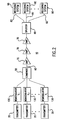
- FIG.1 schematically depicts a modulation format adjusting optical transponder 30.
- Transponder 30 receives an optical signal output by an optical transmitter.
- the input optical signal is converted by optoelectronic converter 32, typically a photodiode, to an electrical signal.
- the resultant electrical signal is amplified by amplifier 34, and routed through clock and data recovery circuit 35.
- the electrical signal passes to modulator driver 39 which drives modulator 38.
- modulator 38 is an external modulator such as a Mach-Zehnder modulator, other techniques for modulating the optical signal including electroabsorption modulators and direct modulation can be used in the present invention.
- Transponder 30 includes an optical source, such as laser 36, for delivering a non-information-bearing optical carrier signal to the laser output waveguide.
- laser 36 is a DFB semiconductor diode laser, generally comprising one or more III-V semiconductor materials, commercially available from a wide variety of suppliers such as Fujitsu, GEC Marconi, and Hewlett-Packard.
- the laser outputs an optical carrier signal at a particular optical wavelength, ⁇ 1 (which, in the case of a WDM optical system, is a wavelength corresponding to a demultiplexer wavelength included in a receiving system).
- Laser driver 37 provides the required laser bias current through a suitable power supply (not shown) as well as thermal control of the laser wavelength.
- An optical wave in a single mode fiber of a certain center frequency has three parameters which can continuously vary with time: amplitude, phase (frequency), and state of polarization.
- modulation format is that one of these attributes, or a coupled combination of these, is made to vary in accordance with the information being imparted to that optical wave. The other parameters are not constrained to follow the information signal. Two modulation formats are different if the coupled confirmation of optical wave parameters (which can refer to a single parameter being varied) are substantially different.
- Modulator 38 uses a modulation format different from the modulation format of the optical signal input to optoelectronic converter 32.
- modulation format refers to the variation of one or more optical parameters such as amplitude, phase (frequency), and state of polarization to impart information to a carrier optical signal.
- the incident optical signals are amplitude modulated.
- Transponders 30 employ modulators with power flat modulation formats such as frequency shift key (FSK) or polarization shift key (PolSK) to create optical signals which do not create time-dependent power variations within the optical system.
- FSK frequency shift key
- PolSK polarization shift key
- a particularly preferred modulation format creates a non-zero chirped optical signal, a modulation format which varies both the amplitude and phase of the optical signal.
- incident amplitude-modulated optical signals from optical transmitters can be converted to optical signals with a power-flat modulation format.
- the invention encompasses any transponder which uses a modulator having a modulation format, whether amplitude, frequency, phase, or polarization based (or a combination thereof), which is different from the modulation format of the incident optical signal.
- modulation formats are described in further detail in the Gowar reference, cited above, and in Schwartz, Information Transmission, Modulation and Noise, (McGraw-Hill, New York), c. 1990.
- FIG. 2 depicts a wavelength division multiplexed optical communication system 10 employing the modulation format adjusting transponders of FIG. 1 as optical remodulators.
- Optical communication system 10 takes optical transmission signals from diverse optical transmitters and other optical signal sources and maps the signal sources onto a wavelength division optical communication system, i.e., a communication system in which individual optical signals correspond to optical channels within a wavelength division multiplexed optical signal carried on an optical waveguide.
- optical transmitters 20 are used to provide the information that will be carried by the optical channels within the WDM optical system.
- Optical transmitters 20 generally includes a laser, such as a DFB semiconductor laser, and a modulator for creation of an information-bearing optical signal.
- information -bearing optical signal refers to an optical signal which has been coded with information, including, but not limited to, audio signals, video signals, and computer data, generally through modulation.
- the laser of optical transmitter 10 can be directly modulated.
- transmitters may form part of an existing optical system
- Typical transmitters emit wavelengths ranging from about 1300 to 1600 nm.
- Transmitters in current optical communication systems and various optical modulation techniques employed therein are described in Gowar, Optical Communication Systems .
- Optical transmitters suitable for use in the present invention are commercially available from NEC, Fujitsu, Alcatel, and Nortel.
- Optical communication system 10 uses the modulation format adjusting transponders 30 of FIG. 1 as remodulators 130 for receiving the transmitted information-bearing optical signal and outputting an information-bearing optical signal at a WDM optical system channel wavelength ⁇ j .
- the subscript j ranges from 1 to 16 for the exemplary optical system of FIG. 1 but can also be, for example, 4, 8, or 32 depending upon the capacity needs of the optical route services by the system.
- the wavelengths emitted by the remodulators are selected to be within the 1500 nanometer range, the range in which the minimum signal attenuation occurs for silica-based fibers. More particularly, the wavelengths emitted by the remodulators are selected to be in the range from 1530 to 1560 nanometers. However, other wavelength bands may be selected according to overall system requirements.
- Each optical channel is routed to optical combiner 50 for conveyance to optical waveguide 60.
- Optical combiner 50 is selected from any passive optical component which can combine plural wavelengths into a single output medium. Frequently, optical splitters used to divide a signal among plural outputs are used as optical combiners, operated in reverse fashion from the splitter. Exemplary optical combiners include 1 x N passive splitters available from Coming, Inc., Coming, NY, 1 x N wideband single mode splitters available from IOT Integr Of Optik GmbH, Waghausel-Kirrlach, Germany, and fused fiber combiners available from Gould, Inc., Millersville, MD. The combination of channels forms a multiplexed optical signal which is output to waveguide 60.
- Optical waveguide 60 is typically a single-mode optical fiber such as SMF-28, available from Corning, and TRUEWAVE, available from AT&T Corp./Lucent Technologies, and is the principal transmission medium for the optical communication system.
- SMF-28 available from Corning
- TRUEWAVE available from AT&T Corp./Lucent Technologies
- any optical waveguide which is capable of transporting multiple optical wavelengths can be employed as waveguide 60 in optical system 10.
- optical amplifiers 70 are selected from any device which directly increases the strength of plural optical signals without the need for optical-to-electrical conversion.
- optical amplifiers 70 are selected from optical waveguides doped with rare earth ions such as erbium, neodymium, praseodymium, ytterbium, or mixtures thereof.
- rare earth ions such as erbium, neodymium, praseodymium, ytterbium, or mixtures thereof.
- Optical amplifiers, their materials, and their operation are further described in Gowar, Ed. Optical Communication Systems, and in Desurvire, Erbium-Doped Fiber Amplifiers, (John Wiley & Sons, Inc., NY), c.
- each channel Following transmission and amplification of the multiplexed optical signals along waveguide 60, each channel must be demultiplexed and routed to the receiver designated for the particular ⁇ j channel.
- the multiplexed signal is input to optical splitter 80 which places a portion of the multiplexed signal onto plural output paths 82.
- Each output path 82 optically communicates with a receiving system 90.
- Optical splitter 80 is selected from any optical device which can divide an input optical signal and place it onto plural output paths. Exemplary splitters include passive optical components such as those components described for use as optical combiner 50.
- Receiving systems 90 typically include wavelength selectors (not shown) for selecting the particular channel, ⁇ j from the multiplexed signal and a receiver (not shown). Exemplary receiving systems are described in U.S. Patent No. 5,504,609.
Landscapes
- Engineering & Computer Science (AREA)
- Computer Networks & Wireless Communication (AREA)
- Signal Processing (AREA)
- Physics & Mathematics (AREA)
- Electromagnetism (AREA)
- Optical Communication System (AREA)
Abstract
Description
- The invention relates to optical transponders generally and, more particularly, to optical transponders which change the modulation format of incident optical signals.
- Optical communication systems are a substantial constituent of communication networks. The expression "optical communication system," as used herein, relates to any system which uses optical signals to convey information across an optical waveguiding medium. Such optical systems include, but are not limited to, telecommunications systems, cable television systems, and local area networks (LANs). Optical systems are described in Gowar, Ed. Optical Communication Systems, (Prentice Hall, NY) c. 1993.
- Optical transmitters are typically available in a particular modulation format. Depending upon the transmission medium for a given optical system, it may be desirable to use a specific modulation format to enhance the transmission characteristics of the launched optical signal.
- In some optical systems wavelength division multiplexing (WDM) is employed to increase the capacity of the fiber optic network. In a WDM system, plural optical channels are carried over a single waveguide, each channel being assigned a particular wavelength. To provide compatibility of the WDM format with existing networks, it is desirable to convert a signal from a received transmission wavelength to a specific channel wavelength within the WDM system. In our prior patents U.S. 5,504,609 and 5,726,784 a series of optical remodulators are used to take input signals from various optical transmitters and output the information onto optical channels within the channel plan of a WDM optical system. Typically, the modulation formats of the optical signals output by the optical transmitters and the remodulators is the same. However, depending upon the type of optical receivers employed and the transmission characteristics of the optical system, it may be desirable to change the modulation format of the optical transmitters to a format which is better suited to transmission in the WDM optical system.
- Thus, there is a need in the art for optical transponders which can change the modulation format of incident optical signals. There is a further need in the art for improved WDM optical communication systems which can receive incoming optical transmitter signals of various modulation formats and place the information onto WDM system optical channels in a different modulation format from that of the transmitter optical signals.
- US 5504609, over which the independent claim is characterised, discloses a multi channel optical communication system wherein each transmission channel comprises a remodulator for altering a modulation format of the signal transmitted from this channel.
- EP0477699 discloses an optical communications system comprising a plurality of channels, each channel having allocated to it a different microwave frequency. In one embodiment a modulator modulates angle modulated optical signals into intensity modulated optical signals.
- According to the present invention there is provided a wavelength division multiplexed optical communication system.
- The present invention comprises a modulation format adjusting optical transponder for receiving an incident optical signal of a first modulation format and outputting an optical signal having a different modulation format. The transponder includes an optical-to-electrical conversion element configured to receive an information-bearing optical signal having a first modulation format and output an electrical signal corresponding to information from the incident optical signal. The transponder includes a laser for outputting an optical carrier signal at a selected wavelength and a modulator communicating with the optical-to-electfical conversion element and with the laser. The modulator places the information from the incident optical signal onto the optical signal output by the laser, creating a modulated optical output signal having a second modulation format different from the first modulation format. Advantageously, the optical transponders of the present invention can take optical signals in a common modulation format, such as amplitude modulation. The output optical signals are in a power-flat modulation format, such as frequency shift key (FSK) modulation. The modulation format adjusting optical transponders of the present invention can be used as remodulators for wavelength division multiplexed optical systems.
- Advantages of the present invention will be apparent from the following detailed description of the presently preferred embodiments thereof, given by way of example only.
- FIG. 1 schematically depicts a modulation format adjusting optical transponder;
- FIG. 2 schematically depicts a wavelength division multiplexed optical communication system employing the optical transponder of FIG. 1 as an optical remodulator.
-
- Turning to the drawings in detail, FIG.1 schematically depicts a modulation format adjusting
optical transponder 30.Transponder 30 receives an optical signal output by an optical transmitter. The input optical signal is converted byoptoelectronic converter 32, typically a photodiode, to an electrical signal. The resultant electrical signal is amplified byamplifier 34, and routed through clock anddata recovery circuit 35. Following retiming, the electrical signal passes tomodulator driver 39 which drivesmodulator 38. (It is noted that whilemodulator 38 is an external modulator such as a Mach-Zehnder modulator, other techniques for modulating the optical signal including electroabsorption modulators and direct modulation can be used in the present invention.) -
Transponder 30 includes an optical source, such aslaser 36, for delivering a non-information-bearing optical carrier signal to the laser output waveguide. In an exemplary embodiment,laser 36 is a DFB semiconductor diode laser, generally comprising one or more III-V semiconductor materials, commercially available from a wide variety of suppliers such as Fujitsu, GEC Marconi, and Hewlett-Packard. The laser outputs an optical carrier signal at a particular optical wavelength, λ1 (which, in the case of a WDM optical system, is a wavelength corresponding to a demultiplexer wavelength included in a receiving system).Laser driver 37 provides the required laser bias current through a suitable power supply (not shown) as well as thermal control of the laser wavelength. - An optical wave in a single mode fiber of a certain center frequency has three parameters which can continuously vary with time: amplitude, phase (frequency), and state of polarization. What is meant by "modulation format" is that one of these attributes, or a coupled combination of these, is made to vary in accordance with the information being imparted to that optical wave. The other parameters are not constrained to follow the information signal. Two modulation formats are different if the coupled confirmation of optical wave parameters (which can refer to a single parameter being varied) are substantially different.
Modulator 38 uses a modulation format different from the modulation format of the optical signal input tooptoelectronic converter 32. As used herein, the expression "modulation format" refers to the variation of one or more optical parameters such as amplitude, phase (frequency), and state of polarization to impart information to a carrier optical signal. Typically, the incident optical signals are amplitude modulated.Transponders 30 employ modulators with power flat modulation formats such as frequency shift key (FSK) or polarization shift key (PolSK) to create optical signals which do not create time-dependent power variations within the optical system. A particularly preferred modulation format creates a non-zero chirped optical signal, a modulation format which varies both the amplitude and phase of the optical signal. Using the modulation format adjusting optical transponders, incident amplitude-modulated optical signals from optical transmitters can be converted to optical signals with a power-flat modulation format. However, it is understood that the invention encompasses any transponder which uses a modulator having a modulation format, whether amplitude, frequency, phase, or polarization based (or a combination thereof), which is different from the modulation format of the incident optical signal. Various modulation formats are described in further detail in the Gowar reference, cited above, and in Schwartz, Information Transmission, Modulation and Noise, (McGraw-Hill, New York), c. 1990. - FIG. 2 depicts a wavelength division multiplexed
optical communication system 10 employing the modulation format adjusting transponders of FIG. 1 as optical remodulators.Optical communication system 10 takes optical transmission signals from diverse optical transmitters and other optical signal sources and maps the signal sources onto a wavelength division optical communication system, i.e., a communication system in which individual optical signals correspond to optical channels within a wavelength division multiplexed optical signal carried on an optical waveguide. - In the exemplary embodiment of FIG. 2,
optical transmitters 20 are used to provide the information that will be carried by the optical channels within the WDM optical system.Optical transmitters 20 generally includes a laser, such as a DFB semiconductor laser, and a modulator for creation of an information-bearing optical signal. The expression "information -bearing optical signal," as used herein, refers to an optical signal which has been coded with information, including, but not limited to, audio signals, video signals, and computer data, generally through modulation. Alternatively, particularly for short-reach optical transmitters, the laser ofoptical transmitter 10 can be directly modulated. Because some of the transmitters may form part of an existing optical system, a wide variety of transmitters emitting in a broad range of wavelengths can be accommodated in the optical communication system of the present invention, thus ensuring compatibility with currently-deployed transmission equipment. Typical transmitters emit wavelengths ranging from about 1300 to 1600 nm. Transmitters in current optical communication systems and various optical modulation techniques employed therein are described in Gowar, Optical Communication Systems. Optical transmitters suitable for use in the present invention are commercially available from NEC, Fujitsu, Alcatel, and Nortel. -
Optical communication system 10 uses the modulationformat adjusting transponders 30 of FIG. 1 asremodulators 130 for receiving the transmitted information-bearing optical signal and outputting an information-bearing optical signal at a WDM optical system channel wavelength λj. The subscript j ranges from 1 to 16 for the exemplary optical system of FIG. 1 but can also be, for example, 4, 8, or 32 depending upon the capacity needs of the optical route services by the system. Typically, the wavelengths emitted by the remodulators are selected to be within the 1500 nanometer range, the range in which the minimum signal attenuation occurs for silica-based fibers. More particularly, the wavelengths emitted by the remodulators are selected to be in the range from 1530 to 1560 nanometers. However, other wavelength bands may be selected according to overall system requirements. - Each optical channel is routed to
optical combiner 50 for conveyance tooptical waveguide 60.Optical combiner 50 is selected from any passive optical component which can combine plural wavelengths into a single output medium. Frequently, optical splitters used to divide a signal among plural outputs are used as optical combiners, operated in reverse fashion from the splitter. Exemplary optical combiners include 1 x N passive splitters available from Coming, Inc., Coming, NY, 1 x N wideband single mode splitters available from IOT Integrierte Optik GmbH, Waghausel-Kirrlach, Germany, and fused fiber combiners available from Gould, Inc., Millersville, MD. The combination of channels forms a multiplexed optical signal which is output towaveguide 60.Optical waveguide 60 is typically a single-mode optical fiber such as SMF-28, available from Corning, and TRUEWAVE, available from AT&T Corp./Lucent Technologies, and is the principal transmission medium for the optical communication system. However, any optical waveguide which is capable of transporting multiple optical wavelengths can be employed aswaveguide 60 inoptical system 10. - Optionally interposed along
optical waveguide 60 are one or moreoptical amplifiers 70.Optical amplifiers 70 are selected from any device which directly increases the strength of plural optical signals without the need for optical-to-electrical conversion. In general,optical amplifiers 70 are selected from optical waveguides doped with rare earth ions such as erbium, neodymium, praseodymium, ytterbium, or mixtures thereof. Optical amplifiers, their materials, and their operation are further described in Gowar, Ed. Optical Communication Systems, and in Desurvire, Erbium-Doped Fiber Amplifiers, (John Wiley & Sons, Inc., NY), c. 1994, and Bjarklev, Optical Fiber Amplifiers: Design and System Applications, (Artech House, Norwood, MA) c. 1993. An exemplary optical amplifier configuration is disclosed in U.S. Patent 5,696,615. Alternatively, other optical amplifiers, such as semiconductor optical amplifiers, may be used alongtransmission line 60. - Following transmission and amplification of the multiplexed optical signals along
waveguide 60, each channel must be demultiplexed and routed to the receiver designated for the particular λj channel. The multiplexed signal is input tooptical splitter 80 which places a portion of the multiplexed signal ontoplural output paths 82. Eachoutput path 82 optically communicates with a receivingsystem 90.Optical splitter 80 is selected from any optical device which can divide an input optical signal and place it onto plural output paths. Exemplary splitters include passive optical components such as those components described for use asoptical combiner 50. Receivingsystems 90 typically include wavelength selectors (not shown) for selecting the particular channel, λj from the multiplexed signal and a receiver (not shown). Exemplary receiving systems are described in U.S. Patent No. 5,504,609. - While the foregoing invention has been described in terms of the embodiments discussed above, numerous variations are possible.
Claims (4)
- A wavelength division multiplexed optical communication system (10) for transmitting a plurality of optical communication channels on an optical waveguide (60) each optical communication channel having a distinct channel wavelength (λ1, λ2... λn) the optical communication system (10) comprising:characterised in that said second modulation format is a power flat modulation format.a first set of a plurality of optical transmitters (20), each optical transmitter (20) configured to transmit an information-bearing optical signal having a first modulation format;a plurality of remodulators (130) optically communicating with a respective one of the plurality of optical transmitters (20) in the first set of optical transmitters (20) the remodulators placing information from the information-bearing optical signals of the first set of optical transmitters (20) onto optical channels in the wavelength division multiplexed optical communication system (10) each of the remodulators (130) comprising:an optical-to-electrical conversion element (32) for receiving a transmitter information-bearing optical signal and outputting an electrical signal corresponding to information from the transmitter optical signal;a laser (36) for outputting an optical signal having a wavelength corresponding to an optical channel in the wavelength division multiplexed optical communication system;modulation means (38) communicating with the optical-to-electrical conversion element (32) and with the laser (36) for placing the information from the transmitter optical signal onto the optical signal output by the laser (36) the modulation means creating a modulated optical channel having a second modulation format different from the first modulation format;an optical waveguide (60);an optical combining element (50) optically communicating with the optical channels produced by the remodulators (130), the optical combining element combining the remodulator optical channels to form a multiplexed optical signal output to the optical waveguide (60);a plurality of optical selectors (80) optically communicating with the optical waveguide, each optical selector configured to select one or more optical channels in the wavelength division multiplexed optical communication system; anda plurality of optical receivers (90) optically communicating with the optical selectors (80),
- A wavelength division multiplexed optical communication system (10) as claimed in claim 1, wherein the first modulation format is amplitude modulation and the second modulation format is frequency shift key modulation.
- A wavelength division multiplexed optical communication system as claimed in claim 1, wherein the first modulation format is amplitude modulation and the second modulation format is polarization shift key modulation.
- A wavelength division multiplexed optical communication system as claimed in claim 1, wherein the first modulation format is amplitude modulation and the second modulation format is amplitude and phase modulation.
Applications Claiming Priority (3)
| Application Number | Priority Date | Filing Date | Title |
|---|---|---|---|
| US862930 | 1992-04-03 | ||
| US08/862,930 US6101011A (en) | 1997-05-29 | 1997-05-29 | Modulation format adjusting optical transponders |
| PCT/US1998/009932 WO1998054854A1 (en) | 1997-05-29 | 1998-05-29 | Modulation format adjusting optical transponders |
Publications (2)
| Publication Number | Publication Date |
|---|---|
| EP0981869A1 EP0981869A1 (en) | 2000-03-01 |
| EP0981869B1 true EP0981869B1 (en) | 2005-10-19 |
Family
ID=25339770
Family Applications (1)
| Application Number | Title | Priority Date | Filing Date |
|---|---|---|---|
| EP98924772A Expired - Lifetime EP0981869B1 (en) | 1997-05-29 | 1998-05-29 | Modulation format adjusting optical transponders |
Country Status (6)
| Country | Link |
|---|---|
| US (2) | US6101011A (en) |
| EP (1) | EP0981869B1 (en) |
| AU (1) | AU7686298A (en) |
| CA (1) | CA2291610A1 (en) |
| DE (1) | DE69831941T2 (en) |
| WO (1) | WO1998054854A1 (en) |
Families Citing this family (36)
| Publication number | Priority date | Publication date | Assignee | Title |
|---|---|---|---|---|
| US6101011A (en) * | 1997-05-29 | 2000-08-08 | Ciena Corporation | Modulation format adjusting optical transponders |
| US6583905B1 (en) * | 1998-05-30 | 2003-06-24 | Cisco Photonics Italy S.R.L. | Apparatus and method for reducing SPM/GVD in optical systems |
| US6717201B2 (en) * | 1998-11-23 | 2004-04-06 | Micron Technology, Inc. | Capacitor structure |
| US6721508B1 (en) | 1998-12-14 | 2004-04-13 | Tellabs Operations Inc. | Optical line terminal arrangement, apparatus and methods |
| US7031612B2 (en) * | 2000-07-18 | 2006-04-18 | Multiplex, Inc. | Optical transponders and transceivers |
| AU2002231322A1 (en) * | 2000-10-30 | 2002-05-15 | Pharmaseq, Inc. | Method and apparatus for a photo-activated transponder |
| US20040197101A1 (en) * | 2001-02-05 | 2004-10-07 | Sasser Gary D. | Optical transceiver module with host accessible on-board diagnostics |
| US7302186B2 (en) * | 2001-02-05 | 2007-11-27 | Finisar Corporation | Optical transceiver and host adapter with memory mapped monitoring circuitry |
| US7079775B2 (en) | 2001-02-05 | 2006-07-18 | Finisar Corporation | Integrated memory mapped controller circuit for fiber optics transceiver |
| US7149430B2 (en) * | 2001-02-05 | 2006-12-12 | Finsiar Corporation | Optoelectronic transceiver having dual access to onboard diagnostics |
| US7346278B2 (en) * | 2001-02-05 | 2008-03-18 | Finisar Corporation | Analog to digital signal conditioning in optoelectronic transceivers |
| WO2002075403A1 (en) * | 2001-03-16 | 2002-09-26 | Photuris, Inc. | Method and apparatus for providing gain equalizing to an optical signal in an optical communication system |
| AU2002257061A1 (en) * | 2001-03-16 | 2002-10-03 | Photuris, Inc. | Wavelength division multiplexed optical communication system having a reconfigurable optical switch and a tunable backup laser transmitter |
| US7068948B2 (en) * | 2001-06-13 | 2006-06-27 | Gazillion Bits, Inc. | Generation of optical signals with return-to-zero format |
| US6975642B2 (en) | 2001-09-17 | 2005-12-13 | Finisar Corporation | Optoelectronic device capable of participating in in-band traffic |
| US6862302B2 (en) * | 2002-02-12 | 2005-03-01 | Finisar Corporation | Maintaining desirable performance of optical emitters over temperature variations |
| US7437079B1 (en) | 2002-06-25 | 2008-10-14 | Finisar Corporation | Automatic selection of data rate for optoelectronic devices |
| US7809275B2 (en) * | 2002-06-25 | 2010-10-05 | Finisar Corporation | XFP transceiver with 8.5G CDR bypass |
| US7486894B2 (en) * | 2002-06-25 | 2009-02-03 | Finisar Corporation | Transceiver module and integrated circuit with dual eye openers |
| US7561855B2 (en) * | 2002-06-25 | 2009-07-14 | Finisar Corporation | Transceiver module and integrated circuit with clock and data recovery clock diplexing |
| US7664401B2 (en) * | 2002-06-25 | 2010-02-16 | Finisar Corporation | Apparatus, system and methods for modifying operating characteristics of optoelectronic devices |
| US7477847B2 (en) * | 2002-09-13 | 2009-01-13 | Finisar Corporation | Optical and electrical channel feedback in optical transceiver module |
| US7317743B2 (en) * | 2002-11-08 | 2008-01-08 | Finisar Corporation | Temperature and jitter compensation controller circuit and method for fiber optics device |
| US7230961B2 (en) | 2002-11-08 | 2007-06-12 | Finisar Corporation | Temperature and jitter compensation controller circuit and method for fiber optics device |
| DE60304148T2 (en) * | 2003-05-05 | 2006-08-24 | Alcatel | Network element for use in an optical transmission network, in particular in a DWDM transmission network |
| US7426586B2 (en) * | 2003-12-15 | 2008-09-16 | Finisar Corporation | Configurable input/output terminals |
| JP4284199B2 (en) * | 2004-01-26 | 2009-06-24 | 株式会社日立コミュニケーションテクノロジー | Optical cross-connect device and network management device |
| US7373090B2 (en) * | 2004-03-26 | 2008-05-13 | Intel Corporation | Modulator driver circuit with selectable on-chip termination |
| US7630631B2 (en) * | 2004-04-14 | 2009-12-08 | Finisar Corporation | Out-of-band data communication between network transceivers |
| US8639122B2 (en) * | 2004-07-02 | 2014-01-28 | Finisar Corporation | Filtering digital diagnostics information in an optical transceiver prior to reporting to host |
| US7447438B2 (en) * | 2004-07-02 | 2008-11-04 | Finisar Corporation | Calibration of digital diagnostics information in an optical transceiver prior to reporting to host |
| US7532820B2 (en) | 2004-10-29 | 2009-05-12 | Finisar Corporation | Systems and methods for providing diagnostic information using EDC transceivers |
| US8204374B2 (en) * | 2004-12-10 | 2012-06-19 | Ciena Corporation | Reconfigurable multichannel (WDM) optical ring network with optical shared protection |
| US20090245813A1 (en) * | 2008-03-31 | 2009-10-01 | Kitel Technologies Llc | Modulator driver with multi-channel active alignment |
| US8159956B2 (en) | 2008-07-01 | 2012-04-17 | Finisar Corporation | Diagnostics for serial communication busses |
| IN2014DN03502A (en) * | 2011-12-22 | 2015-05-15 | Ericsson Telefon Ab L M |
Family Cites Families (15)
| Publication number | Priority date | Publication date | Assignee | Title |
|---|---|---|---|---|
| EP0042229B1 (en) * | 1980-06-16 | 1984-11-14 | The Post Office | Digital transmission systems |
| DE3379767D1 (en) * | 1982-09-02 | 1989-06-01 | British Telecomm | Optical communication |
| EP0772312A3 (en) * | 1990-09-14 | 1997-09-03 | Fujitsu Ltd | Optical communication system with sub-carrier multiplexing |
| GB2254746B (en) * | 1991-04-12 | 1995-03-29 | Northern Telecom Europ Ltd | Optical transmitter |
| JPH06224882A (en) * | 1992-10-03 | 1994-08-12 | Canon Inc | Optical FSK receiver and optical FDM-FSK transmission system using the same |
| CA2118616C (en) * | 1993-03-11 | 1999-09-14 | Thomas Edward Darcie | Optical network based on remote interrogation of terminal equipment |
| DE4333405A1 (en) * | 1993-09-30 | 1995-04-06 | Siemens Ag | Method for re-adjusting a frequency or phase modulation shift of frequency or phase-modulated transmitted light |
| US5483372A (en) * | 1994-11-29 | 1996-01-09 | International Business Machines Corporation | Single and multichannel transmission over long distances using repeated level-crossing remodulation |
| US5726784A (en) * | 1995-05-11 | 1998-03-10 | Ciena Corp. | WDM optical communication system with remodulators and diverse optical transmitters |
| US5504609A (en) * | 1995-05-11 | 1996-04-02 | Ciena Corporation | WDM optical communication system with remodulators |
| US5784184A (en) * | 1995-05-11 | 1998-07-21 | Ciena Corporation | WDM Optical communication systems with remodulators and remodulating channel selectors |
| US5625327A (en) * | 1995-07-13 | 1997-04-29 | Gnuco Technology Corporation | Modified Colpitts oscillator for driving an antenna coil and generating a clock signal |
| US5594384A (en) * | 1995-07-13 | 1997-01-14 | Gnuco Technology Corporation | Enhanced peak detector |
| US5960040A (en) * | 1996-12-05 | 1999-09-28 | Raytheon Company | Communication signal processors and methods |
| US6101011A (en) * | 1997-05-29 | 2000-08-08 | Ciena Corporation | Modulation format adjusting optical transponders |
-
1997
- 1997-05-29 US US08/862,930 patent/US6101011A/en not_active Expired - Lifetime
-
1998
- 1998-05-29 WO PCT/US1998/009932 patent/WO1998054854A1/en not_active Ceased
- 1998-05-29 EP EP98924772A patent/EP0981869B1/en not_active Expired - Lifetime
- 1998-05-29 AU AU76862/98A patent/AU7686298A/en not_active Abandoned
- 1998-05-29 CA CA002291610A patent/CA2291610A1/en not_active Abandoned
- 1998-05-29 DE DE69831941T patent/DE69831941T2/en not_active Expired - Fee Related
-
2000
- 2000-03-06 US US09/519,828 patent/US6256127B1/en not_active Expired - Lifetime
Also Published As
| Publication number | Publication date |
|---|---|
| EP0981869A1 (en) | 2000-03-01 |
| WO1998054854A1 (en) | 1998-12-03 |
| DE69831941T2 (en) | 2006-05-24 |
| US6101011A (en) | 2000-08-08 |
| CA2291610A1 (en) | 1998-12-03 |
| US6256127B1 (en) | 2001-07-03 |
| DE69831941D1 (en) | 2005-11-24 |
| AU7686298A (en) | 1998-12-30 |
Similar Documents
| Publication | Publication Date | Title |
|---|---|---|
| US6256127B1 (en) | Modulation format adjusting optical transponders | |
| US5938309A (en) | Bit-rate transparent WDM optical communication system with remodulators | |
| US5726784A (en) | WDM optical communication system with remodulators and diverse optical transmitters | |
| US5715076A (en) | Remodulating channel selectors for WDM optical communication systems | |
| US5784184A (en) | WDM Optical communication systems with remodulators and remodulating channel selectors | |
| US5504609A (en) | WDM optical communication system with remodulators | |
| US5557439A (en) | Expandable wavelength division multiplexed optical communications systems | |
| US7317877B2 (en) | Optical communications systems, devices, and methods | |
| US5696615A (en) | Wavelength division multiplexed optical communication systems employing uniform gain optical amplifiers | |
| US7369780B2 (en) | Remodulating channel selectors for WDM optical communication systems | |
| US7593646B2 (en) | Upgraded optical communication system with increased transmission capacity and method | |
| Jia et al. | Simultaneous generation of independent wired and wireless services using a single modulator in millimeter-wave-band radio-over-fiber systems | |
| Lim et al. | Technique for increasing optical spectral efficiency in millimetre-wave WDM fibre-radio | |
| JP2021118541A (en) | Optical amplification in optical network | |
| EP1903707B1 (en) | Remodulators for WDM optical communication systems | |
| JP4810366B2 (en) | Wavelength conversion type wavelength division multiplexing transmission equipment | |
| US11121797B1 (en) | Optical system for compensating for signal loss | |
| US20040240771A1 (en) | Device and method for receiving, processing and transmitting optical an electrical signals and method for manufacturing such a device | |
| Hickey | Combined modulation formats for the STARNET coherent wavelength-division multiplexed computer communication network | |
| Su et al. | Convergence of RoF and access systems employing dual parallel modulator in the central station |
Legal Events
| Date | Code | Title | Description |
|---|---|---|---|
| PUAI | Public reference made under article 153(3) epc to a published international application that has entered the european phase |
Free format text: ORIGINAL CODE: 0009012 |
|
| 17P | Request for examination filed |
Effective date: 19991222 |
|
| AK | Designated contracting states |
Kind code of ref document: A1 Designated state(s): BE DE FR GB IT NL SE |
|
| 17Q | First examination report despatched |
Effective date: 20040216 |
|
| GRAP | Despatch of communication of intention to grant a patent |
Free format text: ORIGINAL CODE: EPIDOSNIGR1 |
|
| GRAS | Grant fee paid |
Free format text: ORIGINAL CODE: EPIDOSNIGR3 |
|
| GRAA | (expected) grant |
Free format text: ORIGINAL CODE: 0009210 |
|
| AK | Designated contracting states |
Kind code of ref document: B1 Designated state(s): BE DE FR GB IT NL SE |
|
| PG25 | Lapsed in a contracting state [announced via postgrant information from national office to epo] |
Ref country code: NL Free format text: LAPSE BECAUSE OF FAILURE TO SUBMIT A TRANSLATION OF THE DESCRIPTION OR TO PAY THE FEE WITHIN THE PRESCRIBED TIME-LIMIT Effective date: 20051019 Ref country code: IT Free format text: LAPSE BECAUSE OF FAILURE TO SUBMIT A TRANSLATION OF THE DESCRIPTION OR TO PAY THE FEE WITHIN THE PRESCRIBED TIME-LIMIT;WARNING: LAPSES OF ITALIAN PATENTS WITH EFFECTIVE DATE BEFORE 2007 MAY HAVE OCCURRED AT ANY TIME BEFORE 2007. THE CORRECT EFFECTIVE DATE MAY BE DIFFERENT FROM THE ONE RECORDED. Effective date: 20051019 Ref country code: BE Free format text: LAPSE BECAUSE OF FAILURE TO SUBMIT A TRANSLATION OF THE DESCRIPTION OR TO PAY THE FEE WITHIN THE PRESCRIBED TIME-LIMIT Effective date: 20051019 |
|
| REG | Reference to a national code |
Ref country code: GB Ref legal event code: FG4D |
|
| REF | Corresponds to: |
Ref document number: 69831941 Country of ref document: DE Date of ref document: 20051124 Kind code of ref document: P |
|
| PG25 | Lapsed in a contracting state [announced via postgrant information from national office to epo] |
Ref country code: SE Free format text: LAPSE BECAUSE OF FAILURE TO SUBMIT A TRANSLATION OF THE DESCRIPTION OR TO PAY THE FEE WITHIN THE PRESCRIBED TIME-LIMIT Effective date: 20060119 |
|
| NLV1 | Nl: lapsed or annulled due to failure to fulfill the requirements of art. 29p and 29m of the patents act | ||
| PGFP | Annual fee paid to national office [announced via postgrant information from national office to epo] |
Ref country code: GB Payment date: 20060522 Year of fee payment: 9 |
|
| PGFP | Annual fee paid to national office [announced via postgrant information from national office to epo] |
Ref country code: DE Payment date: 20060817 Year of fee payment: 9 |
|
| PLBE | No opposition filed within time limit |
Free format text: ORIGINAL CODE: 0009261 |
|
| STAA | Information on the status of an ep patent application or granted ep patent |
Free format text: STATUS: NO OPPOSITION FILED WITHIN TIME LIMIT |
|
| 26N | No opposition filed |
Effective date: 20060720 |
|
| EN | Fr: translation not filed | ||
| PG25 | Lapsed in a contracting state [announced via postgrant information from national office to epo] |
Ref country code: FR Free format text: LAPSE BECAUSE OF FAILURE TO SUBMIT A TRANSLATION OF THE DESCRIPTION OR TO PAY THE FEE WITHIN THE PRESCRIBED TIME-LIMIT Effective date: 20061208 |
|
| GBPC | Gb: european patent ceased through non-payment of renewal fee |
Effective date: 20070529 |
|
| PG25 | Lapsed in a contracting state [announced via postgrant information from national office to epo] |
Ref country code: DE Free format text: LAPSE BECAUSE OF NON-PAYMENT OF DUE FEES Effective date: 20071201 |
|
| PG25 | Lapsed in a contracting state [announced via postgrant information from national office to epo] |
Ref country code: GB Free format text: LAPSE BECAUSE OF NON-PAYMENT OF DUE FEES Effective date: 20070529 |
|
| PG25 | Lapsed in a contracting state [announced via postgrant information from national office to epo] |
Ref country code: FR Free format text: LAPSE BECAUSE OF FAILURE TO SUBMIT A TRANSLATION OF THE DESCRIPTION OR TO PAY THE FEE WITHIN THE PRESCRIBED TIME-LIMIT Effective date: 20051019 |