EP0981844B1 - Tunable external cavity laser and appropriate housing - Google Patents
Tunable external cavity laser and appropriate housing Download PDFInfo
- Publication number
- EP0981844B1 EP0981844B1 EP98922315A EP98922315A EP0981844B1 EP 0981844 B1 EP0981844 B1 EP 0981844B1 EP 98922315 A EP98922315 A EP 98922315A EP 98922315 A EP98922315 A EP 98922315A EP 0981844 B1 EP0981844 B1 EP 0981844B1
- Authority
- EP
- European Patent Office
- Prior art keywords
- laser
- housing
- section
- dispersive element
- external cavity
- Prior art date
- Legal status (The legal status is an assumption and is not a legal conclusion. Google has not performed a legal analysis and makes no representation as to the accuracy of the status listed.)
- Expired - Lifetime
Links
- 230000033001 locomotion Effects 0.000 claims abstract description 92
- 239000000853 adhesive Substances 0.000 claims description 11
- 230000001070 adhesive effect Effects 0.000 claims description 11
- 239000003292 glue Substances 0.000 claims description 11
- 238000009826 distribution Methods 0.000 claims description 7
- 238000000926 separation method Methods 0.000 claims description 3
- 241000282326 Felis catus Species 0.000 claims description 2
- 239000004568 cement Substances 0.000 claims 6
- 238000013461 design Methods 0.000 description 24
- 238000005452 bending Methods 0.000 description 7
- 238000004873 anchoring Methods 0.000 description 3
- 230000008859 change Effects 0.000 description 3
- 238000004519 manufacturing process Methods 0.000 description 3
- 238000000034 method Methods 0.000 description 3
- 238000009304 pastoral farming Methods 0.000 description 3
- 230000008901 benefit Effects 0.000 description 2
- 230000006872 improvement Effects 0.000 description 2
- 238000012986 modification Methods 0.000 description 2
- 230000004048 modification Effects 0.000 description 2
- 230000003287 optical effect Effects 0.000 description 2
- 230000003071 parasitic effect Effects 0.000 description 2
- 229910052761 rare earth metal Inorganic materials 0.000 description 2
- 150000002910 rare earth metals Chemical class 0.000 description 2
- 239000004065 semiconductor Substances 0.000 description 2
- 239000004593 Epoxy Substances 0.000 description 1
- 230000009471 action Effects 0.000 description 1
- 238000013459 approach Methods 0.000 description 1
- 230000001276 controlling effect Effects 0.000 description 1
- 230000002079 cooperative effect Effects 0.000 description 1
- 239000013078 crystal Substances 0.000 description 1
- 239000006185 dispersion Substances 0.000 description 1
- 238000006073 displacement reaction Methods 0.000 description 1
- 230000000694 effects Effects 0.000 description 1
- 239000000835 fiber Substances 0.000 description 1
- 239000011521 glass Substances 0.000 description 1
- 238000003754 machining Methods 0.000 description 1
- 230000013011 mating Effects 0.000 description 1
- 230000036316 preload Effects 0.000 description 1
- 238000001228 spectrum Methods 0.000 description 1
- 238000012360 testing method Methods 0.000 description 1
- 238000013519 translation Methods 0.000 description 1
Images



Classifications
-
- H—ELECTRICITY
- H01—ELECTRIC ELEMENTS
- H01S—DEVICES USING THE PROCESS OF LIGHT AMPLIFICATION BY STIMULATED EMISSION OF RADIATION [LASER] TO AMPLIFY OR GENERATE LIGHT; DEVICES USING STIMULATED EMISSION OF ELECTROMAGNETIC RADIATION IN WAVE RANGES OTHER THAN OPTICAL
- H01S5/00—Semiconductor lasers
- H01S5/10—Construction or shape of the optical resonator, e.g. extended or external cavity, coupled cavities, bent-guide, varying width, thickness or composition of the active region
- H01S5/14—External cavity lasers
- H01S5/141—External cavity lasers using a wavelength selective device, e.g. a grating or etalon
- H01S5/143—Littman-Metcalf configuration, e.g. laser - grating - mirror
-
- H—ELECTRICITY
- H01—ELECTRIC ELEMENTS
- H01S—DEVICES USING THE PROCESS OF LIGHT AMPLIFICATION BY STIMULATED EMISSION OF RADIATION [LASER] TO AMPLIFY OR GENERATE LIGHT; DEVICES USING STIMULATED EMISSION OF ELECTROMAGNETIC RADIATION IN WAVE RANGES OTHER THAN OPTICAL
- H01S3/00—Lasers, i.e. devices using stimulated emission of electromagnetic radiation in the infrared, visible or ultraviolet wave range
- H01S3/10—Controlling the intensity, frequency, phase, polarisation or direction of the emitted radiation, e.g. switching, gating, modulating or demodulating
- H01S3/105—Controlling the intensity, frequency, phase, polarisation or direction of the emitted radiation, e.g. switching, gating, modulating or demodulating by controlling the mutual position or the reflecting properties of the reflectors of the cavity, e.g. by controlling the cavity length
- H01S3/1055—Controlling the intensity, frequency, phase, polarisation or direction of the emitted radiation, e.g. switching, gating, modulating or demodulating by controlling the mutual position or the reflecting properties of the reflectors of the cavity, e.g. by controlling the cavity length one of the reflectors being constituted by a diffraction grating
-
- H—ELECTRICITY
- H01—ELECTRIC ELEMENTS
- H01S—DEVICES USING THE PROCESS OF LIGHT AMPLIFICATION BY STIMULATED EMISSION OF RADIATION [LASER] TO AMPLIFY OR GENERATE LIGHT; DEVICES USING STIMULATED EMISSION OF ELECTROMAGNETIC RADIATION IN WAVE RANGES OTHER THAN OPTICAL
- H01S5/00—Semiconductor lasers
- H01S5/02—Structural details or components not essential to laser action
- H01S5/022—Mountings; Housings
- H01S5/023—Mount members, e.g. sub-mount members
- H01S5/02325—Mechanically integrated components on mount members or optical micro-benches
Definitions
- the invention relates to tunable external cavity lasers and more particularly, to methods and apparatus for tuning external cavity lasers.
- the diffracted beam at the angle normal to the mirror is reflected back onto the grating and from there it is diffracted in a direction opposite the original collimated beam.
- the first order of diffraction of the grating is incident on the mirror, which reflects it back onto the grating, where the first order of diffraction passes back into the gain medium, where it serves to determine the operating wavelength of the laser.
- the output of the system is the zero-order reflection from the grating at grazing incidence. Motion of the mirror with respect to the grating allows the system to be tuned to a desired output wavelength.
- the ECDL has a broad range of selectable center frequencies and a narrow tuning range about each center frequency.
- the pivot point of the designs is inexpensive and precise and allows for simultaneous rotary and lineal motion.
- a housing for a tunable external cavity laser including a gain medium, a reflector, and a dispersive element is disclosed.
- the housing includes: a base section, a motion section, and an actuator.
- the base section includes a proximal and distal portion, and the gain medium and the diffractor mounted at respectively the proximal and distal portions such that a first energy beam emanating from the gain medium strikes the dispersive element leaving the dispersive element as a second beam at an angle with respect to the first beam which depends on wavelength.
- the motion section includes a proximal and a distal portion and a torsional member positioned at the proximal portion and the reflector positioned at the distal portion to reflect the second beam to the gain medium via the dispersive element, and the motion section supported by the base about the torsional member.
- the actuator is in selectively engagable abutment against the distal portion of the motion section to move the reflector with respect to the dispersive element about the torsional member to tune the external cavity laser.
- a tunable external cavity laser assembly in an alternate embodiment of the invention according to claim 2 .
- the tunable external cavity laser assembly includes: a gain medium, a dispersive element, a reflector, a base section, a motion section, and an actuator.
- the base section includes a proximal and distal portion, and the gain medium and the dispersive element mounted at respectively the proximal and distal portions such that a first energy beam emanating from the gain medium strikes the dispersive element leaving the dispersive element as a second beam at an angle with respect to the first beam which depends on wavelength.
- the motion section includes a proximal and a distal portion and a torsional member positioned at the proximal portion and the reflector positioned at the distal portion to reflect the second beam to the gain medium via the dispersive element, and the motion section supported by the base about the torsional member.
- the actuator is in selectively engagable abutment against the distal portion of the motion section to move the reflector with respect to the dispersive element about the torsional member to tune the external cavity laser.
- External cavity laser 100 includes: a gain medium, e.g. laser 102, base 104, pivot 106, motion section 108, positioning screw 110, positioning screw knob 112, a reflector, e.g. mirror 114, and a dispersive element, e.g. diffraction grating 116.
- Motion section 108 is supported on base 104 via pivot 106 at a proximal end of the motion section. A distal end of the motion section is positioned with respect to the base via positioning screw 110 and positioning screw knob 112.
- Mirror 114 is mounted on the motion section such that it faces the diffraction grating 116 which is mounted on an upper surface of the base.
- Laser 102 is also mounted on the base such that the beam 130 it emits strikes the diffraction grating at a grazing angle causing a reflection beam 134 and a first order diffraction beam 132.
- the angle of the first order diffraction beam 132 with respect to the laser beam 130 varies as a function of wavelength.
- the first order diffraction is incident on the mirror 114.
- the first order diffraction is reflected by the mirror back to the laser via the diffraction grating to select a wavelength of the zero-order reflection.
- motion section 108 pivots about pivot 106 under the control of the positioning screw 110.
- Pivot 106 is finely machined to nanometer tolerance to ensure smooth movement over the range of its motion.
- the precise position of the motion section is adjusted by clockwise and counterclockwise rotation of the positioning screw knob 112 which moves the distal end of the motion section toward and away from the base.
- mirror 114 moves in relation to diffraction grating 116.
- Laser beam 130 enters an external cavity formed by the laser at one end, the grating in the middle, and the mirror at the opposite end. Energy from the laser 102, strikes the diffraction grating and is refracted into the mirror, as is shown by beam 132, which represents the first order diffraction.
- a portion of laser beam 130 is reflected as the zero-order reflection beam 134 which exits the external cavity.
- the wavelength of reflection beam 134 exiting the external cavity may be adjusted by positioning the mirror mounted on the motion section to increase and decrease the length of the external cavity.
- acceptable outputs of the ECDL may include the zero-order reflection beam 134 and/or a beam 136 emanating from a partially reflective back facet of the laser 102.
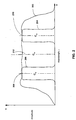
- FIG. 2 shows a comparison of the wavelength tuning range of a prior art tunable external cavity laser as compared to an external cavity laser according to the invention.
- FIG. 2 contains a graph in which wavelength is plotted along the X axis, and amplitude is plotted along the Y axis.
- Waveform 202 represents a waveform characteristic of prior art tunable external cavity lasers.
- the center wavelength C w 212 is fixed.
- the waveform is roughly constant in amplitude over a broad range of wavelengths, due to the precise dimensioning of the pivot of prior art ECDLs and the expense associated therewith. Seldom is such broad-band tunability required by any one user.
- the current invention instead adopts the approach of providing an inexpensive design with narrow-band tunability and an ability to select a center wavelength.
- the current design implements various mechanical features for shifting C w to suit the needs of individual customers.
- Waveforms 204-206 and their respective C w 210-208 represent waveforms characteristic of external cavity lasers according to the current invention. Waveforms 204 and 206 are considerably narrower in bandwidth than is waveform 202.
- C w 208 has a shorter wavelength than C w 212.
- C w 210 has a longer wavelength than C w 212.
- the C w of the current invention can be placed anywhere in relation to the C w 212 of the prior art.
- the prior art using fine tolerance and extremely costly bearings, can achieve a broad range of wavelengths with relatively little resetting of the apparatus.
- the inventive laser using a novel but inexpensive design, operates over a wide range of center wavelengths but cannot be varied as much from the center wavelengths without resetting of the apparatus.
- FIG. 3 shows an exploded isometric view of a three-piece embodiment of a tunable external cavity diode laser housing according to the invention. Shown are base section 302, a positioning member 304, and a motion section 306. Included in base section 302 are mounting holes 320, a gain medium mount 322, a diffraction grating mounting surface 328 and a first pair of base planar surfaces 330A-B. Glue distribution channels 332 are defined in the base mounting surfaces. Included in the positioning member 304 are motion section fastening surfaces 340A-B, set screw holes 344A-B, and a second pair of opposing planar surfaces 342A-B. Included in motion section 306 are anchoring members 360A-B, torsional members 362A-B and a distal portion 368.
- Mounting holes 320 are located in the base section 302, and penetrate the base section.
- Gain medium mount 322 contains gain medium, e.g. laser 324 and is located on the upper surface of the base section.
- the opposing first pair of base planar surfaces 330A-B are located on either long side of the base section, and face outward.
- Glue distribution channels 332 are defined in each of the first pair of base planar surfaces.
- the second pair of opposing planar surfaces 342A-B of the positioning member 304 face inwardly, and are dimensioned to slidably fit together with the first pair of base planar surfaces.
- Set screw holes 344A-B are defined in the positioning member and protrude through each of the second pair of opposing planar surfaces to interface with the first pair of base planar surfaces and to lock the positioning member with respect to the base.
- the slidable positioning of the first pair of base planar surfaces 330A-B and the second pair of opposing planar surfaces 342A-B of the positioning member allows a center wavelength for the ECDL to be selected.
- the same device can be assembled in a multiplicity of center wavelengths by altering the position of the first pair of planar surfaces with respect to the second pair of planar surfaces. This is different from the prior art, which relies on a previously fixed pivot, instead of a slidably cooperative pivot, to achieve the desired positioning.
- a gain medium e.g. laser 324
- a reflector e.g. dihedral reflector 364, and an actuator 366 are shown attached to the distal end of the motion section 306.
- a dispersive element e.g. a diffraction grating, may be attached to diffraction grating mounting surface 328.
- the gain medium may be implemented in a variety of devices including but not limited to: a semiconductor diode chip, a junction laser, a vertical cavity laser, a rare earth doped fiber, or a rare earth doped glass.
- the actuator may be implemented as any number of electrical, mechanical or electro-mechanical devices including but not limited to: a piezoelectric actuator, an electrostrictive actuator, a magnetostrictive actuator, a screw, a micrometer, a solenoid, a bimetalic strip, and a thermal expansion member.
- the dihedral reflector may be replaced with many different reflectors including but not limited to: a dihedral reflector, a cat's eye reflector, a hollow dihedral reflector and a mirror.
- dispersive element may be implemented with a variety of elements including but not limited to: a diffraction grating, a prism, an acousto-optic crystal.
- Motion section fastening surfaces 340A-B are located on an intermediate portion of positioning member 304.
- Torsional members 362A-B are attached to a proximal end of the motion section 306. The torsional portions join the proximal end of the motion section to the anchoring members 360A-B.
- the base section 302 is mounted to a surface using screws passing through mounting holes 320.
- Motion section 306 is mounted on the positioning member 304 by fastening the motion section anchoring members 360A-B to the motion section fastening surfaces 340A-B of the positioning member.
- Generally distal portion 368 serves to locate dihedral reflector 364, which serves to reflect an energy beam from a dispersive element (not shown) mounted on the dispersive element mounting surface 328.
- Positioning member 304 is mounted to the base section via the slidable, cooperative, mating of first and second pairs of opposing planar surfaces 342A-B and 330A-B of respectively the positioning member and the base section.
- the positioning member is stabilized against the base section by the action of set screws passing through set screw holes 344A-B, and glue applied to the surface of either or both of the first and second pairs of planar surfaces.
- the center wavelength can be selected by adjusting the positioning member with respect to the base section, and then fastening one to another once a desired wavelength of light is emitted by the gain medium. Alternatively, locking screws could be used to fasten the planar surfaces.
- the actuator 366 is positioned between the motion section and the positioning member. In an embodiment of the invention the actuator is a piezoelectric device which elongates therefore increasing the separation between the motion section and the positioning member.
- the torsional members 362A-B serve to return the motion section to its original separation with respect to the positioning member, and consequently the dihedral mirror to its original position, with respect to the diffraction grating.
- the wavelength of the zero-order reflection being emitted from the external cavity is adjusted due to the change in the length of the external cavity brought about by the movement of the dihedral mirror.
- the actuator is positioned in the propagation plane of the energy beam which traverses the external cavity from the gain medium, to the diffraction grating to the reflector and back.
- FIG. 4 shows a rear isometric view of the positioning member 304 of an external cavity laser housing according to the invention. The components, structure, and operation of the positioning member have been discussed above.
- FIGS. 5A-C show cross sectional views of alternate embodiments of the torsional members of the motion section. Each of the embodiments exhibits different ratios of bending to torsional stiffness.
- FIG. 5A shows a torsional member 500 with a circular cross section.
- FIG. 5B shows the cross section at A-A of the torsional member 362 shown in FIG. 3 which is generally cross-shaped.
- FIG. 5C shows a torsional member 502 which is rectangular in cross section.
- the torsional member 500 with a circular cross section and a torsional axis 520 exhibits uniform bending stiffness about orthogonal axis 504-506.
- the cross-shaped cross-sectional member 362 with a torsional axis 522 exhibits improvement in the bending stiffness about both of orthogonal axis 508-510 due to the increase in moment of inertia about these axis.
- This design offers advantages when the primary deflection forces on the motion section, caused for example by the actuator, lie along one of or both of these axis.
- An additional advantage of the cross-sectional shape shown in FIG. 5B is that both torsional stiffness about axis 522 and bending. stiffness can independently controlled.
- the torsional member shown in FIG. 5C with a torsional axis 524 exhibits improved bending stiffness about axis 512.
- These variations in cross-sectional design illustrate ways of varying the moments of inertia to improve bending stiffness about an axis and also to control torsional stiffness.
- the ability to vary the moments of inertia is important, for example, when using certain types of actuators, such as piezoelectric actuators.
- Piezoelectric actuators which induce vibrations on the order of kilohertz, can add noise to the external cavity, and create distortions in the modulation of the laser beam, when they induce parasitic motions, It is possible to reduce this noise by varying the size and cross-sectional shape of the torsional portions, thus varying the moment of inertia preferentially along primary axis of deflection.
- the matching of the preload of the motion member to the dynamic characteristics of the actuator may require a variation of the torsional properties of the torsional piece as well.
- the appropriate torsional stiffness for the actuator can be chosen while controlling the bending stiffness so as to reduce parasitic motion in the motion member, such as motions perpendicular to the axis of rotation.
- FIG. 6 shows a front isometric view of the assembled housing of the three-piece tunable external cavity laser shown in FIG. 3.
- the components, structure and function of the tunable external cavity diode laser shown in FIG. 6 are similar to those shown in FIG. 3, with the following differences.
- Shown in FIG. 6 is a dispersive element, e.g. diffraction grating 602, mounted on diffraction grating mounting surface 328.
- the diffraction grating serves to diffract a beam emitted from a gain medium (not shown), and operates cooperatively with dihedral reflector 364 to change the wavelength of the zero-order reflection from the tunable external cavity diode laser by changing the path length of the external cavity.
- actuator 366 mounted between the motion section and the positioning member and abuts each of these.
- the actuator is selectively engageable to increase the distance between the distal end of the motion section and the positioning member, thereby affecting the distance between the dihedral reflector 364 and the diffraction grating 602.
- FIG. 6 Another difference between FIG. 6 and FIG. 3 is that the various parts of the 3-piece embodiment of the inventive housing have been assembled.
- the motion section has been fastened to the positioning member.
- the positioning member 304 has been slidably positioned with respect to the base section 302, via the opposing first and second pairs of planar surfaces 330A-B and 344A-B of respectively the base and the positioning member. These surfaces allow relative movement between the two pieces in two dimensions as suggested by orthogonal arrows 604-606.
- the degree of freedom of the motion section movement is illustrated by arrow 608.
- the various degrees of freedom of the motion section and positioning member permit precise selection of a center wavelength and a length for the external cavity.
- the user of the inventive housing can manipulate the location of the positioning member as desired, and then lock it into place with respect to the base section using glue and/or set screws.
- This coarse method of adjustment is inexpensive compared to the nanometer-scale tolerance bearings of the prior art, yet permits reasonably good precision in the selection of center wavelengths. Additional tuning is available by moving the motion section along arrow 608 with the actuator 366.
- FIG. 7 shows a rear isometric view of the three-piece embodiment of the tunable external cavity diode laser.
- the components, structure, and function of this tunable external cavity diode laser are the same as described above in FIGS. 3 and 6.
- FIG. 8 shows a rear isometric view of a two-piece housing embodiment of a tunable external cavity diode laser according to the invention. While the three piece design offers significant flexibility in selecting the center wavelength and the cavity length, it may be appropriate in some circumstances to use a two-piece design. A two-piece design has fewer moving parts than the three-piece design, and therefore may be less expensive to manufacture. Additionally, there are fewer parts to position during assembly, which speeds final assembly of the housing and laser. Shown is base 800, which includes mounting holes 820, gain medium mount 822 for positioning a gain medium, e.g. laser 324, an opposing pair of planar positioning surfaces 840A-B, and an arch 850.
- base 800 which includes mounting holes 820, gain medium mount 822 for positioning a gain medium, e.g. laser 324, an opposing pair of planar positioning surfaces 840A-B, and an arch 850.
- the mounting holes 820 pass through a lower portion of the base 800.
- the gain medium mount 822 and diffraction grating 602 are shown on an upper surface of the lower portion of the base in a relationship similar to that shown for the three-piece design of FIGS. 3 and 6.
- An arch 850 rises over the lower portion of the base and the gain medium mount.
- FIG. 9 shows motion section 900, which may be used in either a two-piece or a three-piece housing configuration.
- the motion section includes a proximal and distal end respectively 910 and 914.
- Torsional members 904A-B extend from opposite sides of the proximal end.
- At the terminus of each of the torsional portions positioning members 902A-B define a pair of outward facing opposing planar surfaces.
- At the distal end 914 a reflector, e.g. dihedral reflector 364 may be anchored.
- an actuator pad 912 Intermediate the proximal and distal ends is defined an actuator pad 912 into which a piezoelectric actuator may be positioned.
- FIG. 10 shows a rear isometric view of an assembled, two-piece housing comprising the base and motion sections shown in FIGS. 8-9 respectively.
- the components, structure and operation of the tunable external cavity laser 1000 as shown in FIG. 10 are similar to the three-piece design described above in FIGS. 3-7, with the following exception.
- the cooperative action of the opposing pair of planar positioning surfaces 840A-B of the base and the opposing planar surfaces of positioning members 902A-B of the motion section allows slidable positioning of the motion section with respect to the base to select a center wavelength. Once a center wavelength is selected in this manner, the first and second pair of opposing planar positioning surfaces 840A-B are fixed with respect to one another by screws and/or epoxy, adhesive, or glue.
- mounting holes 820 serve to fasten external cavity laser 1000 securely to a test surface.
- An actuator 930 positioned in the actuator pad 912 of the motion section and abutting the arch 850 selectively displaces the motion section away from the arch thereby changing the length of the external cavity formed between the gain medium, the diffraction grating and the dihedral reflector, to alter the wavelength of the zero-order reflection.
- the torsional members 904A-B provide return force to restore the motion section to its original position when the actuator is de-energized.
- the actuator may not only vary in type, as discussed above, but may also vary in location.
- the actuator could be positioned below, behind, or beside the motion section rather than above it. There could be more than one actuator, e.g. an actuator placed on either side of the motion section.
- the actuator(s) could as discussed above, be positioned in the propagation plane formed by light emitted from the laser and the light
- the inventive housing and lasers in a one-piece configuration.
- the one-piece design has fewer moving parts than either the three-piece or two-piece designs, and therefore may less expensive to manufacture.
- the absence of the slidably cooperative "pivots" of the three-piece or two-piece embodiments does limit the amount of flexibility, i.e. degrees of freedom, in selecting center wavelengths or cavity lengths. This loss of flexibility can be offset by the use of actuator-driven cut-outs, that allow further positioning of the reflector and dispersive element with respect to the laser and other optical elements to select the center wavelength of the tunable external cavity laser.
- FIG. 11 shows a side isometric view of a tunable external cavity diode laser 1100, in a one-piece configuration according to the invention.
- the housing includes base section 1102, mounting holes 1104, dispersive element pad 1106, first cut-out 1110, first positioner 1108, first torsional portion 1112, first and second distal motion sections respectively 1122, 1128, second cut-out 1124, second positioner 1126, second torsional portion 1130, third torsional member 1132, back section 1146 and laser mount opening 1144.
- a gain medium e.g. laser 1160
- a dispersive element e.g. diffraction grating 1162
- a reflector e.g. dihedral mirror 1164
- Back section 1146 extends generally orthogonally from the proximal end of the base. Back section 1146 defines a gain medium mount opening 1144 oriented to direct the energy from a gain medium, e.g. laser 1160 at a diffraction grating 1162 mounted on the dispersive element pad 1106.
- the first positioner 1108 adjusts the orientation of the diffraction grating with respect to the base, by causing a torsional deflection about first torsional portion 1112 of the dispersive element pad 1106 with respect to the base section 1102.
- the dihedral mirror is mounted on the lower surface of the first distal motion section 1122.
- the second positioner 1126 adjusts the orientation of the dihedral mirror with respect to the base, by causing a torsional deflection about second torsional portion 1130 of the first distal motion section 1122 with respect to the second distal motion section 1128.
- first and second positioners may be active positioners such as piezoelectric actuators or passive positioners such as set screws. The settings of these positioners will allow the selection of a center wavelength for the tunable external cavity laser.
- the actuator is positioned between the second distal motion section 1128 and the back section 1146.
- the actuator is selectively energizable to torsionally deflect both the first and second distal motion sections 1122, 1128 about the third torsional member 1132 to vary the length of the external cavity and select the wavelength supported by gain medium, e.g. laser 1160.
- gain medium e.g. laser 1160.
- the wavelength of light emitted by the gain medium can be tuned, and the length of the external cavity adjusted, by positioning the dihedral mirror and the diffraction grating with respect to one another using the various actuators.
- FIG. 12 shows a rear isometric view of the one-piece housing for a tunable external cavity laser shown in FIG. 11.
- the components, structure, and function of this tunable external cavity diode laser are the same as described above in FIG. 11.
Landscapes
- Physics & Mathematics (AREA)
- Condensed Matter Physics & Semiconductors (AREA)
- General Physics & Mathematics (AREA)
- Electromagnetism (AREA)
- Optics & Photonics (AREA)
- Lasers (AREA)
- Semiconductor Lasers (AREA)
- Piezo-Electric Or Mechanical Vibrators, Or Delay Or Filter Circuits (AREA)
Abstract
Description
- The invention relates to tunable external cavity lasers and more particularly, to methods and apparatus for tuning external cavity lasers.
- The basic principles of the operation of the tunable laser utilizing a variable length external cavity in conjunction with a diffraction grating and a rotatable mirror are set forth in the publication, "Spectrally Narrow Pulse Dye Laser Without Beam Expander," by Michael G. Littman and Harold J. Metcalf, Applied Optics, vol. 17, No. 14, pages 2224-2227, July 15, 1978. Although the article describes a system which uses a dye laser, the diode laser is easily substituted. The system utilizes a diffraction grating which is filled with an incident collimated laser beam by using the grating at a grazing angle. The diffracted beam at the angle normal to the mirror is reflected back onto the grating and from there it is diffracted in a direction opposite the original collimated beam. The first order of diffraction of the grating is incident on the mirror, which reflects it back onto the grating, where the first order of diffraction passes back into the gain medium, where it serves to determine the operating wavelength of the laser. The output of the system is the zero-order reflection from the grating at grazing incidence. Motion of the mirror with respect to the grating allows the system to be tuned to a desired output wavelength.
- The above mentioned design is susceptible to discontinuities in the output spectrum. These discontinuities are caused by mode hopping which is a change in the integral number of wavelengths in the cavity over the tuning range. To overcome mode hopping U.S. Patent No. 5,319,668 teaches a pivot point for the reflective element, e.g. mirror or dihedral reflector, which provides for simultaneous rotary and linear motion with respect to the grating and thus theoretically overcomes the problem of mode hopping. The pivot point is selected so as to provide an internal cavity length which is exactly an integral number of half wavelengths at three different wavelengths and an exceptionally close (within 1/1000 of one wavelength) match at all other wavelengths within the tuning range. The pivot point calculation takes into account the effect of the dispersion of the gain medium and other optical elements in the system on the cavity length.
- While this arrangement represents a significant improvement compared to previous external cavity diode lasers by providing a pivot capable of tuning over a wide range of wavelengths, it still has a number of drawbacks. Chief among these is the expense of the precision bearings needed for pivoting the reflective element about the pivot point. The bearings are extremely expensive because they need to be stable on a nanometer scale over their range of motion. The fineness of machining needed to accomplish these extreme tolerances makes the price of the bearings extremely high.
- What is needed is a design for tuning external cavity semiconductor diode lasers (ECDL) which does not require the expense and precision of prior art bearing designs and is not susceptible to mode hopping. What is needed is a design that allows for a pivot point for the reflector which provides for both rotary and lineal translation of the reflector with respect to the grating, without expensive bearings. What is needed is a pivot design that will maintaining a constant number of half-wavelengths within the cavity across the entire tuning range without the precision of prior art designs. What is needed is a design that provides for a broad tunable range of output wavelengths.
- An inexpensive external cavity diode laser (ECDL) is disclosed. The ECDL has a broad range of selectable center frequencies and a narrow tuning range about each center frequency. The pivot point of the designs is inexpensive and precise and allows for simultaneous rotary and lineal motion.
- In an embodiment of the invention according to claim 1 a housing for a tunable external cavity laser including a gain medium, a reflector, and a dispersive element is disclosed. The housing includes: a base section, a motion section, and an actuator. The base section includes a proximal and distal portion, and the gain medium and the diffractor mounted at respectively the proximal and distal portions such that a first energy beam emanating from the gain medium strikes the dispersive element leaving the dispersive element as a second beam at an angle with respect to the first beam which depends on wavelength. The motion section includes a proximal and a distal portion and a torsional member positioned at the proximal portion and the reflector positioned at the distal portion to reflect the second beam to the gain medium via the dispersive element, and the motion section supported by the base about the torsional member. The actuator is in selectively engagable abutment against the distal portion of the motion section to move the reflector with respect to the dispersive element about the torsional member to tune the external cavity laser.
- In an alternate embodiment of the invention according to claim 2 a tunable external cavity laser assembly is disclosed. The tunable external cavity laser assembly includes: a gain medium, a dispersive element, a reflector, a base section, a motion section, and an actuator. The base section includes a proximal and distal portion, and the gain medium and the dispersive element mounted at respectively the proximal and distal portions such that a first energy beam emanating from the gain medium strikes the dispersive element leaving the dispersive element as a second beam at an angle with respect to the first beam which depends on wavelength. The motion section includes a proximal and a distal portion and a torsional member positioned at the proximal portion and the reflector positioned at the distal portion to reflect the second beam to the gain medium via the dispersive element, and the motion section supported by the base about the torsional member. The actuator is in selectively engagable abutment against the distal portion of the motion section to move the reflector with respect to the dispersive element about the torsional member to tune the external cavity laser.
-
- FIG. 1 shows a side elevation view of a prior art tunable external cavity laser.
- FIG. 2 shows waveforms representing the wavelength tuning range associated with both tunable external cavity lasers of the prior art and the current invention.
- FIG. 3 shows an exploded isometric view of a three-piece housing for a tunable external cavity laser according to the invention.
- FIG. 4 shows a rear isometric view of the positioning member of the three-piece tunable external cavity laser shown in FIG. 3.
- FIGS. 5A-C show cross-sectional views of alternate embodiments of the torsional member of the three-piece tunable external cavity laser shown in FIG. 3.
- FIG. 6 shows a front isometric view of the assembled housing of the three-piece tunable external cavity laser shown in FIG. 3.
- FIG. 7 shows a rear isometric view of the assembled housing of the three-piece tunable external cavity laser shown in FIG. 3.
- FIG. 8 shows a rear isometric view of the base section of a two-piece housing embodiment of the invention.
- FIG. 9 shows a front isometric view of the motion section of the two-piece housing embodiment of the invention.
- FIG. 10 shows a rear isometric view of an assembled, two-piece housing comprising the base and motion sections shown in FIGS. 8-9 respectively.
- FIG. 11 shows a side isometric view of a one-piece embodiment of the housing for a tunable external cavity laser according to the invention.
- FIG. 12 shows a rear isometric view of the one-piece housing for a tunable external cavity laser shown in FIG. 11.
-
- Prior art tunable external cavity lasers rely upon an expensive bearing to permit tuning of the laser over a broad range of wavelengths. The expense of this bearing results from the requirement that the bearing meet nanometer tolerances over its range of motion. An example of such a
prior art laser 100 is seen in FIG. 1.External cavity laser 100 includes: a gain medium,e.g. laser 102,base 104,pivot 106,motion section 108,positioning screw 110,positioning screw knob 112, a reflector,e.g. mirror 114, and a dispersive element,e.g. diffraction grating 116. -
Motion section 108 is supported onbase 104 viapivot 106 at a proximal end of the motion section. A distal end of the motion section is positioned with respect to the base viapositioning screw 110 and positioningscrew knob 112.Mirror 114 is mounted on the motion section such that it faces the diffraction grating 116 which is mounted on an upper surface of the base. Laser 102 is also mounted on the base such that thebeam 130 it emits strikes the diffraction grating at a grazing angle causing areflection beam 134 and a firstorder diffraction beam 132. The angle of the firstorder diffraction beam 132 with respect to thelaser beam 130 varies as a function of wavelength. The first order diffraction is incident on themirror 114. The first order diffraction is reflected by the mirror back to the laser via the diffraction grating to select a wavelength of the zero-order reflection. - In
operation motion section 108 pivots aboutpivot 106 under the control of thepositioning screw 110.Pivot 106 is finely machined to nanometer tolerance to ensure smooth movement over the range of its motion. The precise position of the motion section is adjusted by clockwise and counterclockwise rotation of thepositioning screw knob 112 which moves the distal end of the motion section toward and away from the base. As the motion section is moved about the pivot point,mirror 114 moves in relation todiffraction grating 116.Laser beam 130 enters an external cavity formed by the laser at one end, the grating in the middle, and the mirror at the opposite end. Energy from thelaser 102, strikes the diffraction grating and is refracted into the mirror, as is shown bybeam 132, which represents the first order diffraction. A portion oflaser beam 130 is reflected as the zero-order reflection beam 134 which exits the external cavity. The wavelength ofreflection beam 134 exiting the external cavity may be adjusted by positioning the mirror mounted on the motion section to increase and decrease the length of the external cavity. As will be obvious to those skilled in the art acceptable outputs of the ECDL may include the zero-order reflection beam 134 and/or abeam 136 emanating from a partially reflective back facet of thelaser 102. - FIG. 2 shows a comparison of the wavelength tuning range of a prior art tunable external cavity laser as compared to an external cavity laser according to the invention. FIG. 2 contains a graph in which wavelength is plotted along the X axis, and amplitude is plotted along the Y axis.
Waveform 202 represents a waveform characteristic of prior art tunable external cavity lasers. Thecenter wavelength C w 212 is fixed. The waveform is roughly constant in amplitude over a broad range of wavelengths, due to the precise dimensioning of the pivot of prior art ECDLs and the expense associated therewith. Seldom is such broad-band tunability required by any one user. - The current invention instead adopts the approach of providing an inexpensive design with narrow-band tunability and an ability to select a center wavelength. In contrast to the prior art designs which have a fixed center wavelength Cw the current design implements various mechanical features for shifting Cw to suit the needs of individual customers. Waveforms 204-206 and their respective Cw 210-208 represent waveforms characteristic of external cavity lasers according to the current invention.
Waveforms waveform 202.C w 208 has a shorter wavelength thanC w 212.C w 210 has a longer wavelength thanC w 212. The Cw of the current invention can be placed anywhere in relation to theC w 212 of the prior art. - The difference in waveforms between the prior art (e.g. 202) and the waveforms, e.g. waveforms 204-206 produced by the laser disclosed herein, shows the tradeoff between the two designs. The prior art, using fine tolerance and extremely costly bearings, can achieve a broad range of wavelengths with relatively little resetting of the apparatus. By comparison, the inventive laser, using a novel but inexpensive design, operates over a wide range of center wavelengths but cannot be varied as much from the center wavelengths without resetting of the apparatus.
- FIG. 3 shows an exploded isometric view of a three-piece embodiment of a tunable external cavity diode laser housing according to the invention. Shown are
base section 302, apositioning member 304, and amotion section 306. Included inbase section 302 are mountingholes 320, a gainmedium mount 322, a diffractiongrating mounting surface 328 and a first pair of baseplanar surfaces 330A-B.Glue distribution channels 332 are defined in the base mounting surfaces. Included in thepositioning member 304 are motion section fastening surfaces 340A-B, set screw holes 344A-B, and a second pair of opposingplanar surfaces 342A-B. Included inmotion section 306 are anchoringmembers 360A-B,torsional members 362A-B and adistal portion 368. - Mounting
holes 320 are located in thebase section 302, and penetrate the base section. Gainmedium mount 322 contains gain medium,e.g. laser 324 and is located on the upper surface of the base section. The opposing first pair of baseplanar surfaces 330A-B are located on either long side of the base section, and face outward.Glue distribution channels 332 are defined in each of the first pair of base planar surfaces. The second pair of opposingplanar surfaces 342A-B of thepositioning member 304, face inwardly, and are dimensioned to slidably fit together with the first pair of base planar surfaces. Set screw holes 344A-B are defined in the positioning member and protrude through each of the second pair of opposing planar surfaces to interface with the first pair of base planar surfaces and to lock the positioning member with respect to the base. - The slidable positioning of the first pair of base
planar surfaces 330A-B and the second pair of opposingplanar surfaces 342A-B of the positioning member allows a center wavelength for the ECDL to be selected. The same device can be assembled in a multiplicity of center wavelengths by altering the position of the first pair of planar surfaces with respect to the second pair of planar surfaces. This is different from the prior art, which relies on a previously fixed pivot, instead of a slidably cooperative pivot, to achieve the desired positioning. - A gain medium,
e.g. laser 324, is shown positioned in gainmedium mount 322. A reflector, e.g.dihedral reflector 364, and anactuator 366 are shown attached to the distal end of themotion section 306. A dispersive element, e.g. a diffraction grating, may be attached to diffractiongrating mounting surface 328. As will be obvious to those skilled in the art the gain medium may be implemented in a variety of devices including but not limited to: a semiconductor diode chip, a junction laser, a vertical cavity laser, a rare earth doped fiber, or a rare earth doped glass. As will be obvious to those skilled in the art the actuator may be implemented as any number of electrical, mechanical or electro-mechanical devices including but not limited to: a piezoelectric actuator, an electrostrictive actuator, a magnetostrictive actuator, a screw, a micrometer, a solenoid, a bimetalic strip, and a thermal expansion member. As will be obvious to those skilled in the art the dihedral reflector may be replaced with many different reflectors including but not limited to: a dihedral reflector, a cat's eye reflector, a hollow dihedral reflector and a mirror. As will be obvious to those skilled in the art the dispersive element may be implemented with a variety of elements including but not limited to: a diffraction grating, a prism, an acousto-optic crystal. Motion section fastening surfaces 340A-B are located on an intermediate portion ofpositioning member 304. Torsionalmembers 362A-B are attached to a proximal end of themotion section 306. The torsional portions join the proximal end of the motion section to theanchoring members 360A-B. - In operation, the
base section 302 is mounted to a surface using screws passing through mountingholes 320.Motion section 306 is mounted on thepositioning member 304 by fastening the motionsection anchoring members 360A-B to the motion section fastening surfaces 340A-B of the positioning member. Generallydistal portion 368 serves to locatedihedral reflector 364, which serves to reflect an energy beam from a dispersive element (not shown) mounted on the dispersiveelement mounting surface 328. Positioningmember 304 is mounted to the base section via the slidable, cooperative, mating of first and second pairs of opposingplanar surfaces 342A-B and 330A-B of respectively the positioning member and the base section. The positioning member is stabilized against the base section by the action of set screws passing through set screw holes 344A-B, and glue applied to the surface of either or both of the first and second pairs of planar surfaces. The center wavelength can be selected by adjusting the positioning member with respect to the base section, and then fastening one to another once a desired wavelength of light is emitted by the gain medium. Alternatively, locking screws could be used to fasten the planar surfaces. Theactuator 366 is positioned between the motion section and the positioning member. In an embodiment of the invention the actuator is a piezoelectric device which elongates therefore increasing the separation between the motion section and the positioning member. When the piezoelectric actuator is de-energized thetorsional members 362A-B serve to return the motion section to its original separation with respect to the positioning member, and consequently the dihedral mirror to its original position, with respect to the diffraction grating. Thus the wavelength of the zero-order reflection being emitted from the external cavity is adjusted due to the change in the length of the external cavity brought about by the movement of the dihedral mirror. In each of the embodiments shown the actuator is positioned in the propagation plane of the energy beam which traverses the external cavity from the gain medium, to the diffraction grating to the reflector and back. This is an advantageous feature of the embodiments in that no forces are generated during the movement of the motion section which tend to torque the dihedral about its longitudinal axis thereby causing displacement of the reflected beam outside the propagation plane. As will be obvious to those skilled in the art the actuator could, however be placed in other locations, outside the propagation plane. - FIG. 4 shows a rear isometric view of the
positioning member 304 of an external cavity laser housing according to the invention. The components, structure, and operation of the positioning member have been discussed above. - FIGS. 5A-C show cross sectional views of alternate embodiments of the torsional members of the motion section. Each of the embodiments exhibits different ratios of bending to torsional stiffness. FIG. 5A shows a
torsional member 500 with a circular cross section. FIG. 5B shows the cross section at A-A of thetorsional member 362 shown in FIG. 3 which is generally cross-shaped. FIG. 5C shows atorsional member 502 which is rectangular in cross section. Thetorsional member 500 with a circular cross section and atorsional axis 520 exhibits uniform bending stiffness about orthogonal axis 504-506. The cross-shapedcross-sectional member 362 with atorsional axis 522 exhibits improvement in the bending stiffness about both of orthogonal axis 508-510 due to the increase in moment of inertia about these axis. This design offers advantages when the primary deflection forces on the motion section, caused for example by the actuator, lie along one of or both of these axis. An additional advantage of the cross-sectional shape shown in FIG. 5B is that both torsional stiffness aboutaxis 522 and bending. stiffness can independently controlled. The torsional member shown in FIG. 5C with atorsional axis 524 exhibits improved bending stiffness aboutaxis 512. These variations in cross-sectional design illustrate ways of varying the moments of inertia to improve bending stiffness about an axis and also to control torsional stiffness. The ability to vary the moments of inertia is important, for example, when using certain types of actuators, such as piezoelectric actuators. Piezoelectric actuators, which induce vibrations on the order of kilohertz, can add noise to the external cavity, and create distortions in the modulation of the laser beam, when they induce parasitic motions, It is possible to reduce this noise by varying the size and cross-sectional shape of the torsional portions, thus varying the moment of inertia preferentially along primary axis of deflection. In certain circumstances the matching of the preload of the motion member to the dynamic characteristics of the actuator may require a variation of the torsional properties of the torsional piece as well. Using the design methods dicussed in connection with FIG. 5B the appropriate torsional stiffness for the actuator can be chosen while controlling the bending stiffness so as to reduce parasitic motion in the motion member, such as motions perpendicular to the axis of rotation. - FIG. 6 shows a front isometric view of the assembled housing of the three-piece tunable external cavity laser shown in FIG. 3. The components, structure and function of the tunable external cavity diode laser shown in FIG. 6 are similar to those shown in FIG. 3, with the following differences. Shown in FIG. 6 is a dispersive element,
e.g. diffraction grating 602, mounted on diffractiongrating mounting surface 328. The diffraction grating serves to diffract a beam emitted from a gain medium (not shown), and operates cooperatively withdihedral reflector 364 to change the wavelength of the zero-order reflection from the tunable external cavity diode laser by changing the path length of the external cavity. Also shown is actuator 366, mounted between the motion section and the positioning member and abuts each of these. The actuator is selectively engageable to increase the distance between the distal end of the motion section and the positioning member, thereby affecting the distance between thedihedral reflector 364 and thediffraction grating 602. - Another difference between FIG. 6 and FIG. 3 is that the various parts of the 3-piece embodiment of the inventive housing have been assembled. The motion section has been fastened to the positioning member. The positioning
member 304 has been slidably positioned with respect to thebase section 302, via the opposing first and second pairs ofplanar surfaces 330A-B and 344A-B of respectively the base and the positioning member. These surfaces allow relative movement between the two pieces in two dimensions as suggested by orthogonal arrows 604-606. The degree of freedom of the motion section movement is illustrated byarrow 608. - The various degrees of freedom of the motion section and positioning member permit precise selection of a center wavelength and a length for the external cavity. The user of the inventive housing can manipulate the location of the positioning member as desired, and then lock it into place with respect to the base section using glue and/or set screws. This coarse method of adjustment is inexpensive compared to the nanometer-scale tolerance bearings of the prior art, yet permits reasonably good precision in the selection of center wavelengths. Additional tuning is available by moving the motion section along
arrow 608 with theactuator 366. - FIG. 7 shows a rear isometric view of the three-piece embodiment of the tunable external cavity diode laser. The components, structure, and function of this tunable external cavity diode laser are the same as described above in FIGS. 3 and 6.
- FIG. 8 shows a rear isometric view of a two-piece housing embodiment of a tunable external cavity diode laser according to the invention. While the three piece design offers significant flexibility in selecting the center wavelength and the cavity length, it may be appropriate in some circumstances to use a two-piece design. A two-piece design has fewer moving parts than the three-piece design, and therefore may be less expensive to manufacture. Additionally, there are fewer parts to position during assembly, which speeds final assembly of the housing and laser. Shown is base 800, which includes mounting
holes 820, gainmedium mount 822 for positioning a gain medium,e.g. laser 324, an opposing pair of planar positioning surfaces 840A-B, and an arch 850. - The mounting
holes 820 pass through a lower portion of thebase 800. The gainmedium mount 822 anddiffraction grating 602 are shown on an upper surface of the lower portion of the base in a relationship similar to that shown for the three-piece design of FIGS. 3 and 6. An arch 850 rises over the lower portion of the base and the gain medium mount. On a lower portion of the arch on opposing sides thereof a first pair of inward facing opposing planar positioning surfaces 840A-B are defined. It is against these surfaces that the motion section shown in FIG. 9 will be slidably positioned to select a center wavelength. - FIG. 9 shows
motion section 900, which may be used in either a two-piece or a three-piece housing configuration. The motion section includes a proximal and distal end respectively 910 and 914. Torsionalmembers 904A-B extend from opposite sides of the proximal end. At the terminus of each of the torsionalportions positioning members 902A-B define a pair of outward facing opposing planar surfaces. At the distal end 914 a reflector, e.g.dihedral reflector 364 may be anchored. Intermediate the proximal and distal ends is defined anactuator pad 912 into which a piezoelectric actuator may be positioned. - FIG. 10 shows a rear isometric view of an assembled, two-piece housing comprising the base and motion sections shown in FIGS. 8-9 respectively. The components, structure and operation of the tunable
external cavity laser 1000 as shown in FIG. 10 are similar to the three-piece design described above in FIGS. 3-7, with the following exception. In FIG. 10 the cooperative action of the opposing pair of planar positioning surfaces 840A-B of the base and the opposing planar surfaces ofpositioning members 902A-B of the motion section allows slidable positioning of the motion section with respect to the base to select a center wavelength. Once a center wavelength is selected in this manner, the first and second pair of opposing planar positioning surfaces 840A-B are fixed with respect to one another by screws and/or epoxy, adhesive, or glue. - In operation, mounting
holes 820 serve to fastenexternal cavity laser 1000 securely to a test surface. Anactuator 930 positioned in theactuator pad 912 of the motion section and abutting the arch 850 selectively displaces the motion section away from the arch thereby changing the length of the external cavity formed between the gain medium, the diffraction grating and the dihedral reflector, to alter the wavelength of the zero-order reflection. Thetorsional members 904A-B provide return force to restore the motion section to its original position when the actuator is de-energized. As will be obvious to those skilled in the art the actuator may not only vary in type, as discussed above, but may also vary in location. For example, the actuator could be positioned below, behind, or beside the motion section rather than above it. There could be more than one actuator, e.g. an actuator placed on either side of the motion section. The actuator(s) could as discussed above, be positioned in the propagation plane formed by light emitted from the laser and the light - In some circumstances, it may be appropriate to manufacture the inventive housing and lasers in a one-piece configuration. For example, the one-piece design has fewer moving parts than either the three-piece or two-piece designs, and therefore may less expensive to manufacture. However, the absence of the slidably cooperative "pivots" of the three-piece or two-piece embodiments does limit the amount of flexibility, i.e. degrees of freedom, in selecting center wavelengths or cavity lengths. This loss of flexibility can be offset by the use of actuator-driven cut-outs, that allow further positioning of the reflector and dispersive element with respect to the laser and other optical elements to select the center wavelength of the tunable external cavity laser.
- FIG. 11 shows a side isometric view of a tunable external
cavity diode laser 1100, in a one-piece configuration according to the invention. The housing includesbase section 1102, mountingholes 1104,dispersive element pad 1106, first cut-out 1110,first positioner 1108, firsttorsional portion 1112, first and second distal motion sections respectively 1122, 1128, second cut-out 1124,second positioner 1126, secondtorsional portion 1130, thirdtorsional member 1132, backsection 1146 andlaser mount opening 1144. To the housing are connected: a gain medium,e.g. laser 1160, a dispersive element,e.g. diffraction grating 1162, a reflector, e.g.dihedral mirror 1164, andactuator 1166. - Mounting
holes 1104 pass through thebase section 1102.Back section 1146 extends generally orthogonally from the proximal end of the base.Back section 1146 defines a gainmedium mount opening 1144 oriented to direct the energy from a gain medium,e.g. laser 1160 at adiffraction grating 1162 mounted on thedispersive element pad 1106. Thefirst positioner 1108 adjusts the orientation of the diffraction grating with respect to the base, by causing a torsional deflection about firsttorsional portion 1112 of thedispersive element pad 1106 with respect to thebase section 1102. The dihedral mirror is mounted on the lower surface of the firstdistal motion section 1122. Thesecond positioner 1126 adjusts the orientation of the dihedral mirror with respect to the base, by causing a torsional deflection about secondtorsional portion 1130 of the firstdistal motion section 1122 with respect to the seconddistal motion section 1128. As will be obvious to those skilled in the art first and second positioners may be active positioners such as piezoelectric actuators or passive positioners such as set screws. The settings of these positioners will allow the selection of a center wavelength for the tunable external cavity laser. The actuator is positioned between the seconddistal motion section 1128 and theback section 1146. The actuator is selectively energizable to torsionally deflect both the first and seconddistal motion sections third torsional member 1132 to vary the length of the external cavity and select the wavelength supported by gain medium,e.g. laser 1160. Thus, the wavelength of light emitted by the gain medium can be tuned, and the length of the external cavity adjusted, by positioning the dihedral mirror and the diffraction grating with respect to one another using the various actuators. - FIG. 12 shows a rear isometric view of the one-piece housing for a tunable external cavity laser shown in FIG. 11. The components, structure, and function of this tunable external cavity diode laser are the same as described above in FIG. 11.
- It will be apparent to those skilled in the art that various modifications and variations can be made in the housing and lasers of the present invention without departing from the spirit or scope of the invention. Thus, it is intended that the present invention cover the modifications and variations of this invention provided they come within the scope of the appended claims and their equivalents.
Claims (23)
- A housing for a tunable external cavity laser including a gain medium (324), a reflector (364), and a dispersive element (602), the housing comprising:a base section (302) including a proximal and distal portion, and the gain medium and the dispersive element mounted at respectively the proximal and distal portions such that a first energy beam emanating from the gain medium strikes the dispersive element leaving the dispersive element as a second beam at an angle with respect to the first beam which depends on wavelength;a motion section (306) including a proximal and a distal portion and a torsional member positioned at the proximal portion and the reflector positioned at the distal portion to reflect the second beam to the gain medium via the dispersive element, and the motion section supported by said base section about the torsional member; andan actuator (304) in selectively engagable abutment against said distal portion of said motion section to move the reflector with respect to the dispersive element about the torsional member to tune the external cavity laser.
- A tunable external cavity laser comprising:a gain medium (324);a dispersive element (602);a reflector (364);a base section (302) including a proximal and distal portion, and the gain medium and the dispersive element mounted at respectively the proximal and distal portions such that a first energy beam emanating from the gain medium strikes the dispersive element leaving the dispersive element as a second beam at an angle with respect to the first beam which depends on wavelength;a motion section (306) including a proximal and a distal portion and a torsional member positioned at the proximal portion and the reflector positioned at the distal portion to reflect the second beam to the gain medium via the dispersive element, and the motion section supported by said base section about the torsional member; andan actuator (304) in selectively engagable abutment against said distal portion of said motion section to move the reflector with respect to the dispersive element about the torsional member to tune the external cavity laser.
- The housing of claim 1 or laser of claim 2, wherein the actuator moves the reflector with respect to the dispersive element in at least one of the following motions: arcuately, linearly and arcuately together with linearly.
- The housing of claim 1 or 3, or the laser of claim 2 or 3, wherein the motion section further comprises a positioning member positioned at opposing ends of the torsional member and slidably positionable with respect to the base section to position the torsional member to select a center wavelength for the external cavity laser.
- The housing or laser of claim 4, wherein the positioning member is formed integral with the opposing ends of the torsional member.
- The housing or laser of claim 4, wherein the positioning member is formed separate from the opposing ends of the torsional member and is fastened to the opposing ends.
- The housing or laser or claim 4, 5 or 6, wherein the positioning member is fastened to the base section at a selected slidable position by means of at least one of: an adhesive, a glue, a cement, a weld and a fastener; to fix a center wavelength for the external cavity laser.
- The housing or laser of any one of claims 4 to 7, wherein the positioning member defines adhesive distribution channels, to increase a cross-section of at least one of: an adhesive, a glue and a cement used to fasten the torsional member to the base section.
- The housing or laser of any one of claims 4 to 8, wherein the base section defines opposing planar surfaces to slidably mate with the positioning member.
- The housing or laser of claim 9, wherein the opposing planar surfaces of the base section further define adhesive distribution channels, to increase a cross-section of at least one of: an adhesive, a glue and a cement used to fasten the torsional member to the base section.
- The housing of claim 1 or laser of claim 2, wherein the motion section further defines a pair of positioning members positioned at opposing ends of the torsional member and slidably positionable with respect to the base section to position the torsional member to select a center wavelength for the external cavity laser.
- The housing or laser of claim 11, wherein the pair of positioning members are formed integral with the opposing ends of the torsional member.
- The housing or laser of claim 11, wherein the pair of positioning members are formed separate from the opposing ends of the torsional member and are fastened to the opposing ends.
- The housing or laser of claim 11, 12 or 13, wherein the pair of positioning members are fastened to the base section at a selected slidable position by means of at least one of: an adhesive, a glue, a cement, a weld and a fastener; to fix a center wavelength for the zero-order reflection.
- The housing or laser of any one of claims 11 to 14, wherein the pair of positioning members defines adhesive distribution channels, to increase a cross-section of at least one of: an adhesive, a glue and a cement used to fasten the torsional member to the base section.
- The housing or laser of claim 11, wherein the base section defines opposing planar surfaces to slidably mate with the pair of positioning members.
- The tunable external cavity laser of claim 16, wherein the opposing planar surfaces of the base section further define adhesive distribution channels, to increase a cross-section of at least one of: an adhesive, a glue and a cement used to fasten the torsional member to the base section.
- The housing or laser of any one of the preceding claims, wherein the distal portion of the motion section further comprises:
a first and a second distal motion section each flexibly joined to the proximal portion of the motion section, and the reflector mounted to the second section, and a positioner to vary a separation between the first and the second distal motion sections to select a center wavelength of the external cavity laser. - The housing or laser of any one of the preceding claims, wherein the reflector comprises one of: a dihedral reflector, a cat's eye reflector, a comer cube and a mirror.
- The housing or laser of any one of the preceding claims, wherein the dispersive element comprises a diffraction grating.
- The housing or laser of any one of the preceding claims, wherein the actuator comprises at least one of: a piezoelectric actuator, an electrostrictive actuator, a magnetostrictive actuator, a screw, a micrometer, a solenoid, a bimetallic strip, and a thermal expansion member.
- The housing or laser of any one of the preceding claims, wherein a cross section of the torsional member is at least one of: circular, rectangular and cross-shaped.
- The housing or laser of any one of the preceding claims, wherein the torsional member includes an asymmetrical cross sectional distribution.
Applications Claiming Priority (3)
| Application Number | Priority Date | Filing Date | Title |
|---|---|---|---|
| US4672897P | 1997-05-16 | 1997-05-16 | |
| US46728P | 1997-05-16 | ||
| PCT/US1998/009949 WO1998052256A1 (en) | 1997-05-16 | 1998-05-15 | External cavity laser pivot design |
Publications (2)
| Publication Number | Publication Date |
|---|---|
| EP0981844A1 EP0981844A1 (en) | 2000-03-01 |
| EP0981844B1 true EP0981844B1 (en) | 2001-11-14 |
Family
ID=21945052
Family Applications (1)
| Application Number | Title | Priority Date | Filing Date |
|---|---|---|---|
| EP98922315A Expired - Lifetime EP0981844B1 (en) | 1997-05-16 | 1998-05-15 | Tunable external cavity laser and appropriate housing |
Country Status (6)
| Country | Link |
|---|---|
| US (1) | US5995521A (en) |
| EP (1) | EP0981844B1 (en) |
| AT (1) | ATE208966T1 (en) |
| AU (1) | AU7489298A (en) |
| DE (1) | DE69802524T2 (en) |
| WO (1) | WO1998052256A1 (en) |
Families Citing this family (17)
| Publication number | Priority date | Publication date | Assignee | Title |
|---|---|---|---|---|
| US6450642B1 (en) * | 1999-01-12 | 2002-09-17 | California Institute Of Technology | Lenses capable of post-fabrication power modification |
| US6683895B2 (en) | 2000-07-26 | 2004-01-27 | Southwest Sciences Incorporated | Wavelength agile external cavity diode laser |
| US8497450B2 (en) * | 2001-02-16 | 2013-07-30 | Electro Scientific Industries, Inc. | On-the fly laser beam path dithering for enhancing throughput |
| US6914917B2 (en) * | 2001-07-24 | 2005-07-05 | Southwest Sciences Incorporated | Discrete wavelength-locked external cavity laser |
| US7027469B2 (en) | 2001-11-30 | 2006-04-11 | Optitune Plc | Tunable filter |
| US6690690B2 (en) * | 2002-05-29 | 2004-02-10 | Lightgage, Inc. | Tunable laser system having an adjustable external cavity |
| US7245642B1 (en) | 2003-01-08 | 2007-07-17 | Southwest Sciences Incorporated | Broadband external cavity diode laser |
| US7286582B1 (en) | 2003-10-08 | 2007-10-23 | Fay Jr Theodore Denis | Optical external cavities having brewster angle wedges |
| US7388890B2 (en) * | 2003-12-12 | 2008-06-17 | Bookham Technology Plc | Piezoelectric-tuned external cavity laser |
| US20060127171A1 (en) * | 2004-12-15 | 2006-06-15 | Choi Dong H | Monolithic rotational flexure bearing and methods of manufacture |
| US7653094B2 (en) * | 2005-03-24 | 2010-01-26 | Mitutoyo Corporation | External cavity laser with flexure tuning element |
| US7518268B2 (en) * | 2005-11-21 | 2009-04-14 | Bookham Technology Plc | Linear stage including an integrated actuator and associated methods |
| DE102007028499B4 (en) * | 2007-06-18 | 2011-08-25 | TOPTICA Photonics AG, 82166 | Tunable diode laser system with external resonator |
| US20090229651A1 (en) * | 2008-03-14 | 2009-09-17 | Fay Jr Theodore Denis | Solar energy production system |
| US20100183038A1 (en) * | 2009-01-16 | 2010-07-22 | Newport Corporation | Magnetic damping of tuning arm in an external cavity laser |
| WO2011019713A1 (en) * | 2009-08-11 | 2011-02-17 | Wedge Technologies | Ultra dark field microscope |
| US9147995B2 (en) * | 2013-03-15 | 2015-09-29 | Daylight Solutions, Inc. | Rapidly tunable laser source assembly with long stroke grating mover |
Family Cites Families (5)
| Publication number | Priority date | Publication date | Assignee | Title |
|---|---|---|---|---|
| US5319668A (en) * | 1992-09-30 | 1994-06-07 | New Focus, Inc. | Tuning system for external cavity diode laser |
| JPH06218565A (en) * | 1993-01-20 | 1994-08-09 | Mitsubishi Electric Corp | Laser processing equipment |
| US5579327A (en) * | 1994-06-06 | 1996-11-26 | Anritsu Corporation | External-cavity tunable wavelength light source using semiconductor laser having phase adjustment area |
| FR2724496B1 (en) * | 1994-09-13 | 1996-12-20 | Photonetics | SINGLE-MODE LASER SOURCE TUNABLE IN WAVELENGTH WITH SELF-ALIGNED EXTERNAL CAVITY |
| DE29606494U1 (en) * | 1996-04-10 | 1997-05-07 | Sacher, Joachim, Dr., 35041 Marburg | Tuner |
-
1998
- 1998-05-14 US US09/079,057 patent/US5995521A/en not_active Expired - Lifetime
- 1998-05-15 AT AT98922315T patent/ATE208966T1/en not_active IP Right Cessation
- 1998-05-15 WO PCT/US1998/009949 patent/WO1998052256A1/en not_active Ceased
- 1998-05-15 DE DE69802524T patent/DE69802524T2/en not_active Expired - Fee Related
- 1998-05-15 AU AU74892/98A patent/AU7489298A/en not_active Abandoned
- 1998-05-15 EP EP98922315A patent/EP0981844B1/en not_active Expired - Lifetime
Also Published As
| Publication number | Publication date |
|---|---|
| EP0981844A1 (en) | 2000-03-01 |
| WO1998052256A1 (en) | 1998-11-19 |
| ATE208966T1 (en) | 2001-11-15 |
| AU7489298A (en) | 1998-12-08 |
| US5995521A (en) | 1999-11-30 |
| DE69802524D1 (en) | 2001-12-20 |
| DE69802524T2 (en) | 2002-06-20 |
Similar Documents
| Publication | Publication Date | Title |
|---|---|---|
| US5995521A (en) | External cavity laser pivot design | |
| US6018535A (en) | External cavity type wavelength-tunable light source | |
| US6829258B1 (en) | Rapidly tunable external cavity laser | |
| US4942583A (en) | Misalignment-tolerant, grating-tuned external-cavity laser | |
| US5325378A (en) | Misalignment-tolerant, grating-tuned external-cavity laser with enhanced longitudinal mode selectivity | |
| US5802085A (en) | Singlemode laser source tunable in wavelength with a self-aligned external cavity | |
| US6282215B1 (en) | Continuously-tunable external cavity laser | |
| EP0693231B1 (en) | Tuning system for external cavity diode laser | |
| EP0883220A2 (en) | External resonator type of wavelength tunable semiconductor laser light source and method for tuning wavelength therefor | |
| WO2009116971A1 (en) | Method and apparatus for wavelength tuning laser diodes | |
| US7286579B2 (en) | Apparatus and method for adjusting external-cavity lasers | |
| US6917478B2 (en) | Scanning head lens assembly | |
| EP2017929A2 (en) | Wavelength tunable light source of external resonator type | |
| US7142569B2 (en) | Tunable laser source and wavelength selection method thereof | |
| US7653094B2 (en) | External cavity laser with flexure tuning element | |
| US5870227A (en) | Scanning head lens assembly | |
| CN114258619B (en) | External cavity laser device, corresponding system and method | |
| US20020090017A1 (en) | Device and method for reduction of spontaneous emission from external cavity lasers | |
| US6731661B2 (en) | Tuning mechanism for a tunable external-cavity laser | |
| US8681825B2 (en) | Grating external-cavity laser and quasi-synchronous tuning method thereof | |
| US7388890B2 (en) | Piezoelectric-tuned external cavity laser | |
| US4048585A (en) | Tuning type laser oscillator apparatus and laser radar system and laser communication system using the same | |
| JP2007234916A (en) | Tunable laser source and method for adjusting its parameter | |
| CA2345124C (en) | Scanning head lens assembly | |
| US8953649B2 (en) | Grating external-cavity semiconductor laser and quasi-synchronous method thereof |
Legal Events
| Date | Code | Title | Description |
|---|---|---|---|
| PUAI | Public reference made under article 153(3) epc to a published international application that has entered the european phase |
Free format text: ORIGINAL CODE: 0009012 |
|
| 17P | Request for examination filed |
Effective date: 19991125 |
|
| AK | Designated contracting states |
Kind code of ref document: A1 Designated state(s): AT BE CH CY DE DK ES FI FR GB GR IE IT LI LU MC NL PT SE |
|
| RIC1 | Information provided on ipc code assigned before grant |
Free format text: 7H 01S 5/10 A, 7H 01S 3/081 B, 7H 01S 5/02 B |
|
| RTI1 | Title (correction) |
Free format text: TUNABLE EXTERNAL CAVITY LASER AND APPROPRIATE HOUSING |
|
| RIC1 | Information provided on ipc code assigned before grant |
Free format text: 7H 01S 5/10 A, 7H 01S 3/081 B, 7H 01S 5/02 B |
|
| RTI1 | Title (correction) |
Free format text: TUNABLE EXTERNAL CAVITY LASER AND APPROPRIATE HOUSING |
|
| GRAG | Despatch of communication of intention to grant |
Free format text: ORIGINAL CODE: EPIDOS AGRA |
|
| 17Q | First examination report despatched |
Effective date: 20010206 |
|
| GRAG | Despatch of communication of intention to grant |
Free format text: ORIGINAL CODE: EPIDOS AGRA |
|
| GRAH | Despatch of communication of intention to grant a patent |
Free format text: ORIGINAL CODE: EPIDOS IGRA |
|
| GRAH | Despatch of communication of intention to grant a patent |
Free format text: ORIGINAL CODE: EPIDOS IGRA |
|
| GRAA | (expected) grant |
Free format text: ORIGINAL CODE: 0009210 |
|
| AK | Designated contracting states |
Kind code of ref document: B1 Designated state(s): AT BE CH CY DE DK ES FI FR GB GR IE IT LI LU MC NL PT SE |
|
| PG25 | Lapsed in a contracting state [announced via postgrant information from national office to epo] |
Ref country code: NL Free format text: LAPSE BECAUSE OF FAILURE TO SUBMIT A TRANSLATION OF THE DESCRIPTION OR TO PAY THE FEE WITHIN THE PRESCRIBED TIME-LIMIT Effective date: 20011114 Ref country code: LI Free format text: LAPSE BECAUSE OF FAILURE TO SUBMIT A TRANSLATION OF THE DESCRIPTION OR TO PAY THE FEE WITHIN THE PRESCRIBED TIME-LIMIT Effective date: 20011114 Ref country code: IT Free format text: LAPSE BECAUSE OF FAILURE TO SUBMIT A TRANSLATION OF THE DESCRIPTION OR TO PAY THE FEE WITHIN THE PRESCRIBED TIME-LIMIT;WARNING: LAPSES OF ITALIAN PATENTS WITH EFFECTIVE DATE BEFORE 2007 MAY HAVE OCCURRED AT ANY TIME BEFORE 2007. THE CORRECT EFFECTIVE DATE MAY BE DIFFERENT FROM THE ONE RECORDED. Effective date: 20011114 Ref country code: GR Free format text: LAPSE BECAUSE OF FAILURE TO SUBMIT A TRANSLATION OF THE DESCRIPTION OR TO PAY THE FEE WITHIN THE PRESCRIBED TIME-LIMIT Effective date: 20011114 Ref country code: FR Free format text: LAPSE BECAUSE OF FAILURE TO SUBMIT A TRANSLATION OF THE DESCRIPTION OR TO PAY THE FEE WITHIN THE PRESCRIBED TIME-LIMIT Effective date: 20011114 Ref country code: FI Free format text: LAPSE BECAUSE OF FAILURE TO SUBMIT A TRANSLATION OF THE DESCRIPTION OR TO PAY THE FEE WITHIN THE PRESCRIBED TIME-LIMIT Effective date: 20011114 Ref country code: CH Free format text: LAPSE BECAUSE OF FAILURE TO SUBMIT A TRANSLATION OF THE DESCRIPTION OR TO PAY THE FEE WITHIN THE PRESCRIBED TIME-LIMIT Effective date: 20011114 Ref country code: BE Free format text: LAPSE BECAUSE OF FAILURE TO SUBMIT A TRANSLATION OF THE DESCRIPTION OR TO PAY THE FEE WITHIN THE PRESCRIBED TIME-LIMIT Effective date: 20011114 Ref country code: AT Free format text: LAPSE BECAUSE OF FAILURE TO SUBMIT A TRANSLATION OF THE DESCRIPTION OR TO PAY THE FEE WITHIN THE PRESCRIBED TIME-LIMIT Effective date: 20011114 |
|
| REF | Corresponds to: |
Ref document number: 208966 Country of ref document: AT Date of ref document: 20011115 Kind code of ref document: T |
|
| REG | Reference to a national code |
Ref country code: CH Ref legal event code: EP |
|
| REG | Reference to a national code |
Ref country code: IE Ref legal event code: FG4D |
|
| REF | Corresponds to: |
Ref document number: 69802524 Country of ref document: DE Date of ref document: 20011220 |
|
| REG | Reference to a national code |
Ref country code: GB Ref legal event code: IF02 |
|
| PG25 | Lapsed in a contracting state [announced via postgrant information from national office to epo] |
Ref country code: SE Free format text: LAPSE BECAUSE OF FAILURE TO SUBMIT A TRANSLATION OF THE DESCRIPTION OR TO PAY THE FEE WITHIN THE PRESCRIBED TIME-LIMIT Effective date: 20020214 Ref country code: PT Free format text: LAPSE BECAUSE OF FAILURE TO SUBMIT A TRANSLATION OF THE DESCRIPTION OR TO PAY THE FEE WITHIN THE PRESCRIBED TIME-LIMIT Effective date: 20020214 Ref country code: DK Free format text: LAPSE BECAUSE OF FAILURE TO SUBMIT A TRANSLATION OF THE DESCRIPTION OR TO PAY THE FEE WITHIN THE PRESCRIBED TIME-LIMIT Effective date: 20020214 |
|
| NLV1 | Nl: lapsed or annulled due to failure to fulfill the requirements of art. 29p and 29m of the patents act | ||
| PG25 | Lapsed in a contracting state [announced via postgrant information from national office to epo] |
Ref country code: MC Free format text: LAPSE BECAUSE OF NON-PAYMENT OF DUE FEES Effective date: 20020515 Ref country code: LU Free format text: LAPSE BECAUSE OF NON-PAYMENT OF DUE FEES Effective date: 20020515 Ref country code: IE Free format text: LAPSE BECAUSE OF NON-PAYMENT OF DUE FEES Effective date: 20020515 |
|
| PG25 | Lapsed in a contracting state [announced via postgrant information from national office to epo] |
Ref country code: ES Free format text: LAPSE BECAUSE OF FAILURE TO SUBMIT A TRANSLATION OF THE DESCRIPTION OR TO PAY THE FEE WITHIN THE PRESCRIBED TIME-LIMIT Effective date: 20020530 |
|
| PG25 | Lapsed in a contracting state [announced via postgrant information from national office to epo] |
Ref country code: CY Free format text: LAPSE BECAUSE OF FAILURE TO SUBMIT A TRANSLATION OF THE DESCRIPTION OR TO PAY THE FEE WITHIN THE PRESCRIBED TIME-LIMIT Effective date: 20020531 |
|
| REG | Reference to a national code |
Ref country code: CH Ref legal event code: PL |
|
| PLBE | No opposition filed within time limit |
Free format text: ORIGINAL CODE: 0009261 |
|
| STAA | Information on the status of an ep patent application or granted ep patent |
Free format text: STATUS: NO OPPOSITION FILED WITHIN TIME LIMIT |
|
| EN | Fr: translation not filed | ||
| 26N | No opposition filed | ||
| REG | Reference to a national code |
Ref country code: IE Ref legal event code: MM4A |
|
| PGFP | Annual fee paid to national office [announced via postgrant information from national office to epo] |
Ref country code: DE Payment date: 20080522 Year of fee payment: 11 |
|
| PGFP | Annual fee paid to national office [announced via postgrant information from national office to epo] |
Ref country code: GB Payment date: 20080521 Year of fee payment: 11 |
|
| GBPC | Gb: european patent ceased through non-payment of renewal fee |
Effective date: 20090515 |
|
| PG25 | Lapsed in a contracting state [announced via postgrant information from national office to epo] |
Ref country code: GB Free format text: LAPSE BECAUSE OF NON-PAYMENT OF DUE FEES Effective date: 20090515 |
|
| PG25 | Lapsed in a contracting state [announced via postgrant information from national office to epo] |
Ref country code: DE Free format text: LAPSE BECAUSE OF NON-PAYMENT OF DUE FEES Effective date: 20091201 |