EP0981242B1 - Shared asymmetric digital subscriber line modem - Google Patents
Shared asymmetric digital subscriber line modem Download PDFInfo
- Publication number
- EP0981242B1 EP0981242B1 EP99306378A EP99306378A EP0981242B1 EP 0981242 B1 EP0981242 B1 EP 0981242B1 EP 99306378 A EP99306378 A EP 99306378A EP 99306378 A EP99306378 A EP 99306378A EP 0981242 B1 EP0981242 B1 EP 0981242B1
- Authority
- EP
- European Patent Office
- Prior art keywords
- digital
- client
- signal
- adsl
- modem
- Prior art date
- Legal status (The legal status is an assumption and is not a legal conclusion. Google has not performed a legal analysis and makes no representation as to the accuracy of the status listed.)
- Expired - Lifetime
Links
Images


Classifications
-
- H—ELECTRICITY
- H04—ELECTRIC COMMUNICATION TECHNIQUE
- H04L—TRANSMISSION OF DIGITAL INFORMATION, e.g. TELEGRAPHIC COMMUNICATION
- H04L12/00—Data switching networks
- H04L12/02—Details
- H04L12/16—Arrangements for providing special services to substations
-
- H—ELECTRICITY
- H04—ELECTRIC COMMUNICATION TECHNIQUE
- H04M—TELEPHONIC COMMUNICATION
- H04M11/00—Telephonic communication systems specially adapted for combination with other electrical systems
- H04M11/06—Simultaneous speech and data transmission, e.g. telegraphic transmission over the same conductors
- H04M11/062—Simultaneous speech and data transmission, e.g. telegraphic transmission over the same conductors using different frequency bands for speech and other data
Definitions
- the present invention relates generally to communications systems and, more particularly, to discrete multi-tone communications systems and digital subscriber line communication systems.
- PCs Remote client personal computers
- Fig. 1 Remote client personal computers
- analog modem speeds are currently limited to 56 thousand bits per second (56 Kbps) because of various constraints of existing telephone networks.
- ADSL Digital Subscriber Line
- DMT discrete multi- tone
- ADSL transmission rates over twisted pair transmission lines can reach as high as 8 million bits per second (8 Mbps) downstream (i.e., towards a client PC) and up to 256 Kbps upstream (towards a server).
- Data transmission rates for ADSL are substantially higher in the downstream direction than in the upstream direction.
- the asymmetric nature of ADSL fits well with data delivery requirements of the Internet. More data is typically transmitted downstream to a client PC than upstream from a client PC to a server.
- lines 20 correspond to individual analog lines, such as local subscriber loops or lines and plain old telephone system (POTS) connections to a telephone company central office (CO) switch.
- Lines 22 correspond to T-1 lines (i.e., lines having bandwidth capabilities of 1.544 Mbps and capable of carrying 24 digitized voiceband connections).
- Lines 24 correspond to T-3 lines (i.e., lines having bandwidth capabilities of 28 T-1 lines and that are time-division multiplexed).
- ADSL implementations typically include a dedicated pair of ADSL modems for each subscriber line. This is in contrast to voice-band modems, where a server only utilizes dedicated modems for each active connection. Requiring a dedicated pair of ADSL modems for each subscriber line may add significantly to the cost of ADSL implementation by telephone service providers.
- One solution involves statistical multiplexing at the remote site.
- Another solution proposes terminating multiple ADSL subscriber lines in a single shared modem at the client side. This may simplify hardware requirements on the telephone network side of each ADSL subscriber line because each subscriber line may share a high-speed transmitter.
- a single shared modem eliminates the need for separate ADSL modems for respective ADSL subscriber lines.
- a limitation of a single shared ADSL modem is that modems on the other end of subscriber lines connected to the shared modem may need to receive the same signal. Accordingly, the bandwidth of the transmitted signal within each frequency band may need to be reduced to accommodate the subscriber line in the group with the lowest bandwidth within each of these frequency bands. Accordingly, the net bandwidth that can be exploited by a shared modem on the server end may be less than that of a single modem on the worst line.
- U.S. Patent No. 5,557,612 to Bingham relates to a system for establishing communications between a central unit and a plurality of remote units wherein access requests include an identification of each remote unit. A particular subchannel is allocated to the remote units by the central unit in an ADSL application. Units requiring bandwidth already allocated to other clients may be denied service.
- U.S. Patent No. 5,608,725 to Grube et al. relates to establishing a communications system wherein a primary site is coupled to a plurality of secondary sites via low pass transmission paths. However, only a single secondary site may be active at a time. Furthermore, the primary site allocates carrier channels of the inbound and outbound low pass transmission paths.
- the present invention facilitates the implementation of ADSL by including statistical multiplexing within an ADSL modem.
- the present invention facilitates the implementation of ADSL without requiring a separate ADSL modem at each end of a subscriber loop.
- the present invention can help to lower costs associated with ADSL implementation.
- the present invention is preferably implemented as a multi-drop Asymmetrical Digital Subscriber Loop (ADSL) server modem having at least two sets of digital front end circuitry which allow for simultaneous analog communication with at least two local loops.
- a shared DSL modem is operably associated with each of the two or more sets of digital front end circuitry and transmits and receives data to and from the digital front end circuitry.
- a digital interface is operably associated with the shared DSL modem and is configured to communicate with an external network.
- the present invention allows for multiple ADSL local loops to be provided by a single modem.
- the shared components reduces the cost of each connection by reducing the number of components required for the modem.
- space constraints may be overcome by allowing multiple local loops to connect to a single modem. Accordingly, the total number of modems required and the total space and power consumption needed to support the modems may be reduced by the multi-drop ADSL modem of the present invention.
- the digital front end circuitry may include a transmit isolation buffer associated with each local loop.
- the transmit isolation buffer isolates transmitted communication signals of the local loops from each other and is operably associated with a transmitter portion of the shared DSL modem.
- the digital front end circuitry may also include a receive isolation buffer associated with each local loop which isolates received communication signals of the local loops from each other and which is operably associated with a receiver of the shared DSL modem.
- the digital front end circuitry may also include a receive filter and a sample and hold circuit associated with each receive filter.
- the filter is operably associated with the receive isolation buffer for filtering signals received by the analog front end circuitry.
- the sample and hold circuit associated with each receive filter receives filtered signals from the corresponding receive filter.
- An analog to digital converter may be associated with each sample and hold circuit to receive a held signal from the corresponding sample and hold circuit and convert the analog signal to a digital signal.
- the shared ADSL modem may include a receiver having a multiplexer and an analog-to-digital converter.
- the multiplexer receives an output of the receive filter of each local loop and provides one of the outputs of one of the receive filters as a multiplexer output.
- the analog-to-digital converter receives the multiplexer output and converts the multiplexer output to a digital signal.
- the receiver may also include a timing equalizer and a memory device.
- the timing equalizer utilizes local loop specific equalizer information to equalize the digital signal from the analog-to-digital converter and to time-domain equalize the digital signal to provide an equalized digital signal.
- the memory device is operably associated with the timing equalizer and stores local loop specific equalizer coefficients.
- the receiver may further include a serial to parallel converter, a Discrete Fourier Transform circuit, a symbol detector, and a memory device operably associated with the symbol detector.
- the serial to parallel converter converts the equalized digital signal from a serial signal to a parallel signal so as to provide a parallel digital signal.
- the Discrete Fourier Transform circuit transforms the parallel digital signal from a time domain signal to a frequency domain signal so as to provide digital frequency coefficients.
- the symbol detector receives the digital frequency coefficients and detects symbols from the frequency domain coefficients based on local loop specific symbol information to provide client specific symbols.
- the memory device operably associated with the symbol detector stores local loop specific symbol information.
- the receiver may also include a decoder and a memory device operably associated with the decoder.
- the decoder receives client specific symbols from the symbol detector, descrambles, provides Reed-Solomon decoding and de-interleaves the symbols based on client specific information to provide client specific data.
- the memory device operably associated with the decoder stores the client specific information.
- the ADSL modem may also include a symbol buffer and a packet buffer for each local loop.
- the symbol buffer receives symbols from the symbol detector and provides symbols to the decoder.
- the packet buffer receives packets from the decoder.
- the ADSL modem may also include a transmitter having an encoder, a memory device operably associated with the encoder, a symbol mapper, and a memory device operably associated with the symbol mapper.
- the encoder receives client specific symbols for transmission on a local loop and scrambles, provides Reed-Solomon encoding and interleaves the symbols based on client specific information to provide client specific symbol data.
- the memory device operably associated with the encoder stores the client specific information.
- the symbol mapper receives client specific symbol data and maps the client specific symbol data to frequency domain symbols based on local loop specific frequency information to provide local loop specific symbol data.
- the memory device operably associated with the symbol mapper stores local loop specific frequency information.
- the transmitter may also include an Inverse Discrete Fourier Transform circuit, a parallel to serial converter, a digital to analog converter, and a transmit filter.
- the Inverse Discrete Fourier Transform circuit transforms the local loop specific symbol data from frequency domain data to a time domain signal so as to provide parallel digital symbol data.
- the parallel to serial converter converts the parallel digital symbol data from a parallel signal to a serial signal so as to provide a serial digital signal.
- the circuit also adds a framing bit and a cyclic prefix.
- the digital to analog converter converts the serial digital signal to an analog signal.
- the transmit filter provides a filtered transmit signal to the transmit isolation buffers.
- methods and computer program products are provided for allowing multiple simultaneous local loops to connect to a single ADSL modem. Operations include isolating the local loops from one another, storing loop dependent information for each connected local loop, and communicating with each ' local loop utilizing the loop dependent information.
- Fig. 1 illustrates an exemplary telephone network of twisted-pair transmission lines and analog modems.
- Fig. 2 schematically illustrates bandwidth burden imposed on a telephone network by an ADSL implementation.
- Fig. 3 schematically illustrates a shared access ADSL modem having a single high-speed shared DSL transmitter configured to handle multiple subscriber lines.
- Fig. 4 schematically illustrates frequency bandwidth allocation for DMT modulation.
- Fig. 5 schematically illustrates operations for carrying out aspects of the present invention.
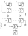
- Fig. 6 is a block diagram of a system including a multi-drop server modem connected to multiple remote client modems according to the present invention.
- Fig. 7 is a block diagram of a particular embodiment of a multi-drop server modem according to the present invention.
- Fig. 8 is a block diagram of a particular embodiment of a client modem according to the present invention.
- an ADSL communication system includes an ADSL transceiver on each end of a subscriber line.
- the ADSL transceivers of a subscriber line communicate with each other to establish a spectral response of the subscriber line. Once spectral response information is exchanged, transmission of data typically begins.
- the sending ADSL transceiver converts data provided in digital format, such as from a video camera, or internet web site images into a sequence of DMT symbols and conveys the DMT symbols to the other ADSL transceiver over the subscriber line.
- the receiving ADSL transceiver Upon receiving a sequence of DMT symbols, the receiving ADSL transceiver recaptures and reroutes the digital data, for example, to a user via a display screen or monitor.
- ADSL Digital Subscriber Line
- the illustrated modem 30 has a single high-speed shared DSL transmitter 32 configured to handle multiple subscriber lines.
- the illustrated shared DSL transmitter 32 receives data from a network server connected by a high-speed communications line through a receiver circuit 34.
- the shared DSL transmitter 32 provides typical modem transmitter functions including error recovery protocols, line coding, filtering, modulation, and the like.
- the shared DSL transmitter 32 is also configured to embed a unique identifier within each signal frame transmitted to a respective remote modem.
- Each subscriber line typically requires its own line interface circuit 38, which isolates the source of the transmit signal from the subscriber line itself in order to keep the POTS and received modem signals for each subscriber line isolated.
- This line interface circuit 38 also provides the mechanism traditionally included within ADSL modems to tap off the analog POTS telephone bandwidth for traditional telephony connections. Because each client PC 29 connected to the shared access ADSL modem 30 receives the same signal, each client PC ADSL modem examines the incoming signal to filter out packets destined for other client PCs. Such filtering may be accomplished by accepting only packets which have an identifier corresponding to a preassigned address for a particular client PC.
- Each modem receiver 36 may be similar to a V.34, V.PCM modem, or ADSL modem receiver, except that the signal is converted from a high frequency pass band to a base band signal via a mixer in the line interface circuit 38 before processing by the modem.
- DMT modulation A generalized illustration of frequency bandwidth allocation for DMT modulation is schematically shown in Fig. 4 .
- the low frequency range 40 is reserved for POTS transmissions. Frequency ranges higher than the POTS frequency range 40 are used for ADSL transmissions. In Fig. 4 , these high frequency ranges are divided into a group of frequency bands 42 for upstream signals and multiple frequency bands 44 for downstream signals.
- DMT modulation is also applicable to systems requiring an echo canceller where upstream frequency bands and downstream frequency bands share a common frequency range. The present invention is equally applicable to systems utilizing an echo canceller.
- a shared ADSL modem uses various line probing techniques to determine for each frequency band what data rate can be supported. The transmitter then splits-up the signal among the supported frequency bands according to the ability of each frequency band to support data throughput.
- the present invention adapts the use of the multiple downstream frequency bands 44 to achieve optimum performance within a system which shares a high-speed digital subscriber loop transmitter among multiple subscriber lines.
- a small number of the downstream frequency bands 44 are allocated as carriers for destination codes of downstream or remote modems.
- frequency bands 44a and 44b are allocated as destination code carriers.
- frequency bands for use as destination code carriers are selected on the basis of consistent throughput capabilities.
- An ADSL frame is an amount of data that fits into one Fast Fourier Transform (FFT).
- FFT Fast Fourier Transform
- Each ADSL frame can have a different destination code.
- One way is to add a control channel to a time domain signal.
- Another way involves the use of bursts of frames all destined for the same client. In this case, a destination code only needs to be sent in the first frame of an initial burst.
- each of the client PC modems sharing a common server modem has a unique destination code, either assigned statically or negotiated at the beginning of a session, such as during a communications handshake.
- One or more destination codes may also be assigned for use during the initial phases of a connection when destination codes are negotiated. All client receivers will process the signal through a FFT.
- a receiver in each client PC modem examines a destination code within a carrier frequency band or bands during each symbol interval and processes data in other frequency bands 44 only if the destination code matches a preassigned destination code.
- a particular client PC modem can ignore downstream frequency bands 44 containing data when a destination code does not match the assigned destination code of the particular client PC modem (i.e., data destined for another client PC).
- the present invention can allow each subscriber line to "tune" its supported frequency bands to optimize bandwidth of a specific copper line, because a destination code will identify a symbol interval as only being valid for a specific subscriber line.
- the shared server ADSL modem tracks which downstream frequency bands 44 are usable for each client PC modem and dynamically adjusts a modulated transmit signal based on which client modem is the intended recipient of the data.
- Each remote modem is assigned a unique destination code (Block 100).
- the assignment of unique destination codes may be performed statically or dynamically during a communications handshake between each remote modem and the shared modem.
- the subscriber line connected to the particular remote modem is probed to determine data rates that can be supported at various frequency bands (Block 102).
- the shared modem then transmits modulated data to each respective remote modem using destination codes per Block 100 above to control the desired recipient using only frequency bands to which the addressed subscriber line has been "tuned". Accordingly, data is preferably transmitted to each remote modem at an optimum data rate for each remote modem, and not at a sub-optimum data rate.
- a destination code is transmitted in a first group of frequency bands and modulated data is transmitted in at least one second group of frequency bands, different from the first group of frequency bands (Block 104).
- Each remote ADSL modem examines a transmitted first group of frequency bands to determine if the first group of frequency bands contains a destination code matching a preassigned destination code of the remote modem (Block 106). If a matching destination code is found, data contained within the second group of frequency bands is demodulated by the remote ADSL modem for use by a respective client PC (Block 108).
- each block of the flowchart illustrations of Fig. 5 and combinations of blocks in the flowchart illustrations of Fig. 5 can be implemented by computer program instructions.
- These program instructions may be provided to a processor to produce a machine, such that the instructions which execute on the processor create means for implementing the functions specified in the flowchart block or blocks.
- the computer program instructions may be executed by a processor to cause a series of operational steps to be performed by the processor to produce a computer implemented process such that the instructions which execute on the processor provide steps for implementing the functions specified in the flowchart block or blocks.
- blocks of the flowchart illustrations support combinations of means for performing the specified functions, combinations of steps for performing the specified functions and program instruction means for performing the specified functions. It will also be understood that each block of the flowchart illustrations, and combinations of blocks in the flowchart illustrations, can be implemented by special purpose hardware-based systems which perform the specified functions or steps, or combinations of special purpose hardware and computer instructions.
- Fig. 6 illustrates one embodiment of a multi- drop server modem connected to multiple client modems according to the present invention.
- multiple workstations 216 may use individual ADSL modems 214 to connect to individual analog front ends 212 of a shared ADSL server modem 210 via individual twisted pair local loops 218.
- the shared ADSL modem 210 then communicates with the digital interface 200 which provides the information from the multiple local loops connected to the analog front ends 212 to another network or processor such as a digital telephone network or Internet Service Provider (ISP).
- ISP Internet Service Provider
- a server function is essentially a mirror image of the corresponding client function. While the client has a high-speed receiver and a lower speed transmitter, the server transmitter matches the high speed of the client receiver, and has a lower speed receiver.
- the client modem requires only minor changes to be compatible with a multi-line server modem.
- the analog front end of the multi-line server modem is significantly more complex than a single line server modem as an analog front end 212 is provided for each local loop.
- the shared functions of the ADSL modem also utilize additional working storage to handle client-specific state variables and coefficients.
- the analog front ends 212 preferably include separate splitters for POTS connections and isolation buffers to prevent signals from one client from coupling into another line.
- Each analog front end 212 also preferably includes a dedicated analog receive filter.
- the analog front end may include an analog multiplexer (Mux) to a common sample-hold circuit followed by a common Analog-to-Digital converter.
- multiple sample-hold circuits may be used with an analog Mux to a common Analog-to-Digital converter.
- a third alternative uses multiple Analog-to-Digital converters, with multiplexing accomplished in the digital domain.
- the complexities of sharing the upstream bandwidth may be reduced by implementing a separate complete receiver for each client as shown in Fig. 3 .
- the server receiver operates at 1/8 the sample rate of the transmitter, a server system with one transmitter and eight receivers would require less than 1/4 the processing required to handle the same 8 clients with individual ADSL modems. Furthermore, this can be done without affecting bandwidth back to the digital interface, since it simply compensates for the asymmetric bit rate of the modems. While this alternative may increase the cost of a fully shared server modem, it may be a reasonable alternative if real-time traffic (i.e. voice or video conferencing) is a significant requirement for the service. Furthermore, the same hardware could potentially adapt to either by using different microcode loads, allowing the service provider to tune the modem density according to the level of service required.
- the number of clients supported by one server modem will be determined by several factors, regardless of whether the receiver function is dedicated per client or shared across a number of clients. For example, the additional memory required per client and the bandwidth allocated to the control channel carrying addressing information to select a specific client may limit the number of clients which can be supported. However, the number of clients per shared modem may ultimately be limited by individual user's expectations for level of service (i.e. response time) which limits the number of clients. Since different service providers may have different ideas as to the level of service their customers expect, the number of clients per server modem is preferably flexible to allow customization for particular users.
- Fig. 7 illustrates a particular embodiment of a shared DSL server modem according to the present invention. As will be appreciated by those of skill in the art, the embodiment illustrated in Fig. 7 may be modified as described above with respect to the division between local loop specific and shared components.
- the multi-drop ADSL modem includes a digital interface 200 which allows connectivity to any device capable of communicating over the digital interface 200.
- the digital interface 200 is bidirectional in that it receives data from the receive section or sections of the modem or provides data to the transmitter portion of the modem.
- the type of digital interface 200 is not dependent on whether the modem supports multiple clients.
- the digital interface may be a high-speed parallel bus which supports Direct Memory Access (DMA) or Bus Master data transfers, such as the PCI bus.
- DMA Direct Memory Access
- Such modems may be used in an installation with multiple slots for ADSL modems, one or more slots for upstream connections, and a slot (or backplane) containing a system control processor and memory.
- the multi-line modem may reduce loading and simplified Bus Master arbitration (due to fewer devices requiring access) for a system which supports a given number of client modem connections.
- the multi-line modem may be able to utilize a serial interface directly to link to a remotely located concentrator, since multiple clients are inherently already statistically multiplexed.
- the present invention should not be limited to any particular digital interface. Any number of suitable bus schemes and interfaces known to those of skill in the art may be used with the present invention to allow communication between the multi-drop ADSL modem and other devices.
- the digital interface provides information to a L2 Framing and CRC Generation function 220.
- a single L2 Framing/CRC Generation function 220 can be shared among multiple connections, leading to an implementation which is essentially the same as required for a single line modem.
- Each L2 Frame will be processed completely and placed in a packet buffer 222 before starting the next frame. This avoids a requirement of saving and restoring client specific intermediate results.
- Supporting multiple connections may require more packet buffers than required for the single line case. As illustrated in Fig. 7 separate buffers 222 per connection would be the upper limit required. However, depending on the mechanism used to control data flow through the physical layer, the number of packet buffers may be reduced significantly below that level. Packet buffering requirements may actually approach the requirements for a single line modem if the L2 frame (equal to 69 physical layer frames) is chosen as the smallest entity directed to a specific connection.
- the packet buffers 222 provide packets of data to an encoder 224.
- the encoder 224 scrambles, Reed-Solomon codes and interleaves the packets. Scrambling, Reed-Solomon Encoding, and Interleaving processes should be essentially the same as that required for a single line server modem, since each L2 frame could be processed completely before moving to the next.
- CRC generation should coordinate multiple packet buffers. Tone ordering is dependent on learned line characteristics, and thus is preferably done differently for each client connection.
- client specific variables 248 are stored and provided to the encoder 224. However, the same routine may be used for each connection by providing the client specific (i.e. local loop specific) information to the encoder 224 for use by the routine.
- the resulting symbols are provided to the symbol buffers 226.
- the upper limit for symbol buffers should be the total number of connections allowed, however fewer may be used.
- the symbol buffers 226 provide the symbols to the symbol mapper 228.
- Symbol Mapping and gain scaling are also dependent on learned line characteristics, and thus must be done differently for each client connection.
- conventional symbol mapping may be used, however, client specific variables are used for the mapping.
- a single routine may process multiple connections by accessing the client specific state variables 246.
- the symbol mapper 228 uses the client specific information to map the symbols to the frequencies of the multi-tone transmission.
- each client may have specific symbol values for each frequency which would be reflected in the stored client specific (i.e. local loop specific) variables 246.
- the output of the symbol mapper 228 may then be provided to a 256 complex symbol buffer 230 which outputs the complex symbols to the Inverse Discrete Fourier Transform (IDFT) circuit 232.
- the IDFT 232 of the present invention may be identical to that of a conventional ADSL modem.
- the IDFT 232 converts the complex frequency domain symbols to real time domain symbols in accordance with well-known Fourier Transform processes.
- the real symbols are provided to a 512 symbol buffer 234 which then provides them to the parallel to serial converter 236 which may insert the framing bit.
- the parallel to serial conversion and insertion of the framing bit and cyclic prefix may be identical to that of a conventional single line ADSL modem.
- the parallel to serial converter provides the serial information to the Digital to Analog converter (D/A) 238 which converts the digital signal to an analog signal.
- the analog signal is provided to the transmit filter 240 which provides the filtered signal to an isolation buffer 242 for each local loop.
- the isolation buffers reduce the likelihood of each local loop interfering with other local loops. From the isolation buffer 242 the analog signal is provided to the local loop.
- the present invention utilizes a client identifier or local loop identifier throughout the transmission processes described above.
- each of the functions such as the encoder 224 and the symbol mapper 228 may utilize the identifier to select the client or local loop specific information to use in their processing.
- Such an identifier may take many forms, such as a header in the data or as a discrete signal decoded from information in the data received by the digital interface 200. Accordingly, the present invention should not be construed as limited to any particular method of providing identification of the local loop associated with data to the various functions of the transmitter of the ADSL modem.
- the receiver of Fig. 7 receives signals from the local loops at isolation buffers 252.
- the isolation buffers serve to isolate each local loop from the other.
- the isolation buffers 252 may provide the received signals to an analog multiplexer 254 which provides one of the signals to an analog to digital converter 256.
- the demarcation between individual components and shared components may vary in different embodiments of the present invention. Thus, the present invention should not be construed as limited to the example of Fig. 7 .
- the analog to digital converter 256 may be a conventional analog to digital converter.
- the analog to digital converter 256 converts the received analog signal to a digital signal which is provided to the time domain equalizer 258.
- a single time-domain equalizer may be used, however, the timing coefficients should be selected from multiple client-specific sets.
- the stored client specific variables 260 may be selected by the equalizer 258 based on the physical line selected by the multiplexer 254. Alternatively, other selection methods may be used, as described with respect to the transmitter portion of the client modem.
- the time domain equalizer 258 provides an equalized digital signal to both the Sync Search function 282 and the serial to parallel converter 262.
- the sync search 282 and parallel to serial converter 262 may be the same as those used in conventional ADSL modems. However, the sync search function 282 may have to be disabled when switching from one client line to another, depending on how quickly switching transients settle out. Ideally, a new client could be transmitting immediately after switching the multiplexer, but at least one physical frame of dead time when switching may be required.
- the serial to parallel converter 262 converts the serial digital signal to a parallel digital signal and provides the parallel signal to 64 real symbol buffers 264.
- the real symbol buffers 264 provide the symbols to the Discrete Fourier Transformation (DFT) function 266 which converts the symbols from the time domain to the frequency domain and provides 32 complex symbols to the complex symbol buffers 268.
- the DFT 266 may be the same as conventional DFT functions.
- the complex symbol buffers 268 then provide the symbols to the symbol detector 284.
- the frequency-domain equalization and symbol detection function 284 is dependent on the line characteristics learned for the specific client connection. Therefore, at each processing interval, a set of client specific coefficients and state variables, coordinated with the state of the front-end multiplexer 254, must be used to process the symbols generated by the DFT 266. Otherwise, the symbol detector 284 may function as a convention ADSL symbol detector.
- the client specific variables 280 may be stored and provided to the symbol detector 284. The selection of the client specific variables 280 may be based on the multiplexer 254 or by other means, as described above.
- the symbol detector 284 outputs the symbols to symbol buffers 270 which provide the symbols to the decoder 272. As with the transmitter, the maximum number of symbol buffers 270 required is one for each local loop.
- the decoder 272 descrambles, Reed-Solomon decodes and de-interleaves the symbols. Descrambling, Reed-Solomon Decoding, and De-interleaving processes should be essentially the same as that required for a single line server modem, since each L2 frame could be processed completely before moving to the next. Some additional complexity may be required to coordinate multiple packet buffers. Tone ordering is dependent on learned line characteristics, and thus must be done differently for each client connection. Therefore, like the symbol detector 284, the decoder 272 will access client specific variables 278 to perform its functions. The selection of the client specific variables 278 may be the same as that described above. A single routine may process multiple connections by accessing the client specific state variables 278.
- the decoder outputs packets to the packet buffers 274 which provide the packets to the L2 Framing/CRC check function 276.
- a single L2 Framing/CRC Check function 276 can be shared among multiple connections.
- the L2 Framing/CRC Check function 276 may be essentially the same as required for a single line modem.
- Each L2 Frame will be processed completely from a packet buffer 274, and placed in a DMA queue before starting the next frame. This avoids a requirement of saving and restoring client specific intermediate results. Supporting multiple connections may require more packet buffers than required for the single line case. Fig.
- the L2 framing/CRC Check function 276 then provides the packets to the digital interface 200 for transmission.
- Fig. 8 illustrates a particular embodiment of a client modem according to the present invention.
- the client ADSL modem according to one embodiment of the present invention includes a digital interface 300 which allows connectivity to any device capable of communicating over the digital interface 300.
- the digital interface 300 is bidirectional in that it receives data from the receive section of the modem or provides data to the transmitter portion of the modem.
- the digital interface 300 may be a conventional digital interface for ADSL modems.
- the digital interface 300 provides information to a L2 Framing and CRC Generation function 320.
- the L2 Framing and CRC generation function 320 may be the same as used in conventional ADSL modems. Each L2 Frame will be processed and placed in a packet buffer 322.
- the packet buffer 322 provides packets of data to an encoder 324.
- the encoder 324 scrambles, Reed-Solomon codes and interleaves the packets. Scrambling, Reed-Solomon Encoding, and Interleaving processes should be essentially the same as that required for a conventional single line modem. Tone ordering is dependent on learned line characteristics and utilizes the state variables 348 which are stored and provided to the encoder 324.
- the resulting symbols are provided to the symbol buffer 326.
- the symbol buffer 326 provides the symbols to the symbol mapper 328.
- Symbol mapping and gain scaling are also dependent on learned line characteristics using the state variables 346.
- the symbol mapper 328 uses the state variables 346 to map the symbols to the frequencies of the multi-tone transmission.
- the symbol mapper 328 may also receive information from the upstream access arbitration function 400 to be utilized in the arbitration for bandwidth between multiple clients and the shared ADSL modem.
- the symbol mapper 328 may be a conventional symbol mapper with the addition of provisions for the particular arbitration or bandwidth allocation scheme employed by the shared ADSL modem. Various such schemes are described below.
- the output of the symbol mapper 328 may then be provided to a 32 complex symbol buffer 330 which outputs the complex symbols to the Inverse Discrete Fourier Transform (IDFT) circuit 332.
- the IDFT 332 of the present invention may be identical to that of a conventional ADSL modem.
- the IDFT 332 converts the complex symbols to real symbols by converting from the frequency domain to the time domain.
- the real symbols are provided to a 64 symbol buffer 334 which then provides them to the parallel to serial converter 336 which may insert the framing bit and cyclic prefix.
- the parallel to serial conversion and insertion of the framing bit and cyclic prefix may be identical to that of a conventional single line ADSL modem.
- the parallel to serial converter 336 provides the serial information to the Digital to Analog converter (D/A) 338 which converts the digital signal to an analog signal.
- the analog signal is provided to the transmit filter 340 which provides the filtered signal to the local loop.
- the receiver of Fig. 8 receives signals from the local loop at receive filter 352.
- the receive filter 352 provides the signal to an analog to digital converter 356.
- the analog to digital converter 356 may be a conventional analog to digital converter.
- the analog to digital converter 356 converts the received analog signal to a digital signal which is provided to the time domain equalizer 358.
- the time-domain equalizer uses stored equalization coefficients 360. A conventional time domain equalizer may be utilized.
- the time domain equalizer 358 provides an equalized digital signal to both the Sync Search function 382 and the serial to parallel converter 362.
- the sync search 382 and serial to parallel converter 362 may be the same as those used in conventional ADSL modems.
- the serial to parallel converter 362 converts the serial digital signal to a parallel digital signal and provides the parallel signal to 512 real symbol buffer 364.
- the real symbol buffer 364 provides the symbols to the Discrete Fourier Transformation (DFT) function 366 which converts the symbols from the time domain to the frequency domain and provides 256 complex symbols to the complex symbol buffer 368.
- the DFT 366 may be the same as conventional DFT functions.
- the complex symbol buffer 368 then provides the symbols to the symbol detector 384.
- the frequency-domain equalization and symbol detection function 384 is dependent on the line characteristics learned for the client connection.
- the symbol detector 384 utilizes the state variables 380 in detecting the symbols.
- the symbol detector 384 may function as a convention ADSL symbol detector however, the symbol detector also detects whether the message is directed to the specific client modem.
- the symbol detector 384 may examine the frequency band(s) allocated to the control channel function, to determine on a frame by frame basis if the set of physical symbols is addressed to that specific.client. If not, those frames are discarded and further processing is not hecessary during that interval. This process could alternately be done only once per superframe (69 frames), depending on the granularity of the multiplexing.
- the symbol detector 384 may also provide information to the upstream access arbitration function 400 for use in the arbitration scheme for allocating bandwidth.
- the symbol detector 384 outputs the symbols to symbol buffer 370 which provides the symbols to the decoder 372.
- the decoder 372 performs descrambling, Reed- Solomon decodeing and de-interleaving.
- the decoder 372 outputs packets to the packet buffer 374 which provide the packets to the L2 Framing/CRC check function 376.
- the L2 framing/CRC Check function 376 then provides the packets to the digital interface 300 for transmission.
- the decoder 372 and L2 Framing/CRC check 376 functions may be the same as conventional client modems. Thus, the decoder 372 may use state variables 378 to perform its functions.
- timing must be synchronized between the transmitter D/A converter and the receiver A/D converter this function is performed by the timing and control function 250 of the server modem and timing and control function 350 in the client modem.
- the synchronization of the converters may be carried out by conventional timing and control functions. Additional control is required in the Multi- line Server to coordinate the sharing of upstream bandwidth.
- the server must know which client is enabled to transmit during each possible transmit frame, and coordinate the control of the analog multiplexer at the front end to select the active client. These functions are performed by the timing and control function 250 in the server modem and the upstream access arbitration function 400 in the client modem.
- a control protocol enables each client to request upstream bandwidth without interfering with current transmission, enables each client to quantify its bandwidth requirements, and enables the server to control which client modem will be allowed to transmit at each possible interval.
- Fixed allocations either time multiplexed or frequency multiplexed may be simplest to implement, but would not make optimum use of available bandwidth.
- Asynchronous access with collision detection is another possibility, but a client may not be able to detect a collision with another client using a different local loop. This would force the server to determine client collisions and request retransmissions.
- a control message could be broadcast to all clients simultaneously to accomplish this.
- bandwidth is separated via Time Division Multiplexing (TDM) between all active clients.
- TDM Time Division Multiplexing
- a protocol which allows each client to either give up some of the allocated bandwidth or request additional bandwidth on a dynamic basis could then be implemented. Alternatively, only a small percent of the bandwidth would be allocated to each client. This guarantees a periodic channel for communicating requests for additional bandwidth. Access to the bandwidth not allocated to any client can then be granted dynamically by the server based on pending requests.
- the shared ADSL modem of the present invention allows for multiple connections by isolating the local loops and then using local loop dependent information to communicate with the local loops.
- This local loop dependent information may be stored in various memory devices, registers, latches or other storage devices known to those of skill in the art.
- the local loop dependent information may be stored in a central storage area or in individual storage areas associated with each modem function. Accordingly, the present invention should not be limited to any particular storage configuration.
- An ADSL modem including a receiver which comprises a symbol detector and a decoder may further comprise: a symbol buffer for each local loop wherein the symbol buffer receives symbols from the symbol detector and provides symbols to the decoder; and/or a packet buffer for each local loop which receives packets from the decoder.
- An ADSL modem including a transmitter which comprises an encoder and a symbol mapper may also comprise: a symbol buffer for each local loop wherein the symbol buffer receives symbols from the encoder and provides symbols to the symbol mapper; and/or a packet buffer for each local loop which receives packets and provides the packets to the encoder.
Abstract
Description
- The present invention relates generally to communications systems and, more particularly, to discrete multi-tone communications systems and digital subscriber line communication systems.
- Remote client personal computers (PCs) are typically connected to the Internet over a telephone network of twisted-pair transmission lines via analog modems, as illustrated in
Fig. 1 . Unfortunately, analog modem speeds are currently limited to 56 thousand bits per second (56 Kbps) because of various constraints of existing telephone networks. - Asymmetrical Digital Subscriber Line (ADSL) technology is currently being developed to extend bandwidth over twisted-pair transmission lines by an order of magnitude. ADSL is based on a discrete multi- tone (DMT) transmission system. ADSL transmission rates over twisted pair transmission lines can reach as high as 8 million bits per second (8 Mbps) downstream (i.e., towards a client PC) and up to 256 Kbps upstream (towards a server). Data transmission rates for ADSL are substantially higher in the downstream direction than in the upstream direction. The asymmetric nature of ADSL fits well with data delivery requirements of the Internet. More data is typically transmitted downstream to a client PC than upstream from a client PC to a server.
- Unfortunately, a significant problem currently plaguing the implementation of ADSL is the bandwidth burden placed on a telephone network by ADSL as illustrated in
Fig. 2 . InFig. 2 ,lines 20 correspond to individual analog lines, such as local subscriber loops or lines and plain old telephone system (POTS) connections to a telephone company central office (CO) switch.Lines 22 correspond to T-1 lines (i.e., lines having bandwidth capabilities of 1.544 Mbps and capable of carrying 24 digitized voiceband connections).Lines 24 correspond to T-3 lines (i.e., lines having bandwidth capabilities of 28 T-1 lines and that are time-division multiplexed). - Although 24 analog POTS connections can be handled by a single T-1 line, 24 ADSL connections utilize almost the entire bandwidth of a T-3 line. This bandwidth constraint is further complicated by the fact that many analog subscriber lines may not terminate at a CO switch. Analog subscriber lines may terminate in remote locations, such as a manhole or utility box in a neighborhood, where a subscriber line is digitized and then routed to a CO switch via a T-1 or T-3 line. Increasing bandwidth for these remote links may be costly and may complicate implementation of ADSL.
- In addition, current ADSL implementations typically include a dedicated pair of ADSL modems for each subscriber line. This is in contrast to voice-band modems, where a server only utilizes dedicated modems for each active connection. Requiring a dedicated pair of ADSL modems for each subscriber line may add significantly to the cost of ADSL implementation by telephone service providers.
- Various solutions have been proposed to alleviate bandwidth constraints and thereby facilitate implementation of ADSL technology. One solution involves statistical multiplexing at the remote site. Another solution proposes terminating multiple ADSL subscriber lines in a single shared modem at the client side. This may simplify hardware requirements on the telephone network side of each ADSL subscriber line because each subscriber line may share a high-speed transmitter. A single shared modem eliminates the need for separate ADSL modems for respective ADSL subscriber lines.
- Unfortunately, a limitation of a single shared ADSL modem is that modems on the other end of subscriber lines connected to the shared modem may need to receive the same signal. Accordingly, the bandwidth of the transmitted signal within each frequency band may need to be reduced to accommodate the subscriber line in the group with the lowest bandwidth within each of these frequency bands. Accordingly, the net bandwidth that can be exploited by a shared modem on the server end may be less than that of a single modem on the worst line.
- Various ways of overcoming limitations with shared ADSL modems have been proposed. For example.
U.S. Patent No. 5,557,612 to Bingham relates to a system for establishing communications between a central unit and a plurality of remote units wherein access requests include an identification of each remote unit. A particular subchannel is allocated to the remote units by the central unit in an ADSL application. Units requiring bandwidth already allocated to other clients may be denied service.U.S. Patent No. 5,608,725 to Grube et al. relates to establishing a communications system wherein a primary site is coupled to a plurality of secondary sites via low pass transmission paths. However, only a single secondary site may be active at a time. Furthermore, the primary site allocates carrier channels of the inbound and outbound low pass transmission paths. - The present invention according to a first aspect facilitates the implementation of ADSL by including statistical multiplexing within an ADSL modem.
- In another aspect, the present invention facilitates the implementation of ADSL without requiring a separate ADSL modem at each end of a subscriber loop.
- The present invention can help to lower costs associated with ADSL implementation.
- The present invention is preferably implemented as a multi-drop Asymmetrical Digital Subscriber Loop (ADSL) server modem having at least two sets of digital front end circuitry which allow for simultaneous analog communication with at least two local loops. A shared DSL modem is operably associated with each of the two or more sets of digital front end circuitry and transmits and receives data to and from the digital front end circuitry. A digital interface is operably associated with the shared DSL modem and is configured to communicate with an external network.
- By providing multiple analog front ends and shared modem components, the present invention allows for multiple ADSL local loops to be provided by a single modem. The shared components reduces the cost of each connection by reducing the number of components required for the modem. Furthermore, space constraints may be overcome by allowing multiple local loops to connect to a single modem. Accordingly, the total number of modems required and the total space and power consumption needed to support the modems may be reduced by the multi-drop ADSL modem of the present invention.
- The digital front end circuitry may include a transmit isolation buffer associated with each local loop. The transmit isolation buffer isolates transmitted communication signals of the local loops from each other and is operably associated with a transmitter portion of the shared DSL modem. The digital front end circuitry may also include a receive isolation buffer associated with each local loop which isolates received communication signals of the local loops from each other and which is operably associated with a receiver of the shared DSL modem.
- The digital front end circuitry may also include a receive filter and a sample and hold circuit associated with each receive filter. The receive
- filter is operably associated with the receive isolation buffer for filtering signals received by the analog front end circuitry. The sample and hold circuit associated with each receive filter receives filtered signals from the corresponding receive filter. An analog to digital converter may be associated with each sample and hold circuit to receive a held signal from the corresponding sample and hold circuit and convert the analog signal to a digital signal.
- The shared ADSL modem may include a receiver having a multiplexer and an analog-to-digital converter. The multiplexer receives an output of the receive filter of each local loop and provides one of the outputs of one of the receive filters as a multiplexer output. The analog-to-digital converter receives the multiplexer output and converts the multiplexer output to a digital signal. The receiver may also include a timing equalizer and a memory device. The timing equalizer utilizes local loop specific equalizer information to equalize the digital signal from the analog-to-digital converter and to time-domain equalize the digital signal to provide an equalized digital signal. The memory device is operably associated with the timing equalizer and stores local loop specific equalizer coefficients.
- The receiver may further include a serial to parallel converter, a Discrete Fourier Transform circuit, a symbol detector, and a memory device operably associated with the symbol detector. The serial to parallel converter converts the equalized digital signal from a serial signal to a parallel signal so as to provide a parallel digital signal. The Discrete Fourier Transform circuit transforms the parallel digital signal from a time domain signal to a frequency domain signal so as to provide digital frequency coefficients. The symbol detector receives the digital frequency coefficients and detects symbols from the frequency domain coefficients based on local loop specific symbol information to provide client specific symbols. The memory device operably associated with the symbol detector stores local loop specific symbol information.
- The receiver may also include a decoder and a memory device operably associated with the decoder. The decoder receives client specific symbols from the symbol detector, descrambles, provides Reed-Solomon decoding and de-interleaves the symbols based on client specific information to provide client specific data. The memory device operably associated with the decoder stores the client specific information.
- The ADSL modem may also include a symbol buffer and a packet buffer for each local loop. The symbol buffer receives symbols from the symbol detector and provides symbols to the decoder. The packet buffer receives packets from the decoder.
- The ADSL modem may also include a transmitter having an encoder, a memory device operably associated with the encoder, a symbol mapper, and a memory device operably associated with the symbol mapper. The encoder receives client specific symbols for transmission on a local loop and scrambles, provides Reed-Solomon encoding and interleaves the symbols based on client specific information to provide client specific symbol data. The memory device operably associated with the encoder stores the client specific information. The symbol mapper receives client specific symbol data and maps the client specific symbol data to frequency domain symbols based on local loop specific frequency information to provide local loop specific symbol data. The memory device operably associated with the symbol mapper stores local loop specific frequency information.
- The transmitter may also include an Inverse Discrete Fourier Transform circuit, a parallel to serial converter, a digital to analog converter, and a transmit filter. The Inverse Discrete Fourier Transform circuit transforms the local loop specific symbol data from frequency domain data to a time domain signal so as to provide parallel digital symbol data. The parallel to serial converter converts the parallel digital symbol data from a parallel signal to a serial signal so as to provide a serial digital signal. The circuit also adds a framing bit and a cyclic prefix. The digital to analog converter converts the serial digital signal to an analog signal. The transmit filter provides a filtered transmit signal to the transmit isolation buffers.
- According to other aspects of the present invention, methods and computer program products are provided for allowing multiple simultaneous local loops to connect to a single ADSL modem. Operations include isolating the local loops from one another, storing loop dependent information for each connected local loop, and communicating with each ' local loop utilizing the loop dependent information.
-
Fig. 1 illustrates an exemplary telephone network of twisted-pair transmission lines and analog modems. -
Fig. 2 schematically illustrates bandwidth burden imposed on a telephone network by an ADSL implementation. -
Fig. 3 schematically illustrates a shared access ADSL modem having a single high-speed shared DSL transmitter configured to handle multiple subscriber lines. -
Fig. 4 schematically illustrates frequency bandwidth allocation for DMT modulation. -
Fig. 5 schematically illustrates operations for carrying out aspects of the present invention. -
Fig. 6 is a block diagram of a system including a multi-drop server modem connected to multiple remote client modems according to the present invention. -
Fig. 7 is a block diagram of a particular embodiment of a multi-drop server modem according to the present invention. -
Fig. 8 is a block diagram of a particular embodiment of a client modem according to the present invention. - The present invention now will be described more fully hereinafter, by way of example, with reference to the accompanying drawings, in which preferred embodiments of the invention are shown. This invention may, however, be embodied in many different forms and should not be construed as limited to the embodiments set forth herein; rather, these embodiments are provided so that this disclosure will be thorough and complete, and will fully convey the scope of the invention to those skilled in the art. Like numbers refer to like elements throughout.
- As is known to those skilled in this art, an ADSL communication system includes an ADSL transceiver on each end of a subscriber line. In general, the ADSL transceivers of a subscriber line communicate with each other to establish a spectral response of the subscriber line. Once spectral response information is exchanged, transmission of data typically begins. The sending ADSL transceiver converts data provided in digital format, such as from a video camera, or internet web site images into a sequence of DMT symbols and conveys the DMT symbols to the other ADSL transceiver over the subscriber line. Upon receiving a sequence of DMT symbols, the receiving ADSL transceiver recaptures and reroutes the digital data, for example, to a user via a display screen or monitor. Using ADSL technology, high bandwidth data can be delivered to client PCs from a server using existing twisted pair transmission lines. ADSL is described in detail in the American National Standards Institute Draft Standard for Telecommunications - Network and Installation Interfaces - Asymmetrical Digital Subscriber Line (ADSL) Interface - ANSI Document No. T1.413, which is incorporated herein by reference in its entirety.
- Referring to
Fig. 3 , a sharedaccess ADSL modem 30 for use with the present invention is illustrated. The illustratedmodem 30 has a single high-speed shared DSL transmitter 32 configured to handle multiple subscriber lines. The illustrated shared DSL transmitter 32 receives data from a network server connected by a high-speed communications line through areceiver circuit 34. The shared DSL transmitter 32 provides typical modem transmitter functions including error recovery protocols, line coding, filtering, modulation, and the like. The shared DSL transmitter 32 is also configured to embed a unique identifier within each signal frame transmitted to a respective remote modem. - Each subscriber line typically requires its own
line interface circuit 38, which isolates the source of the transmit signal from the subscriber line itself in order to keep the POTS and received modem signals for each subscriber line isolated. Thisline interface circuit 38 also provides the mechanism traditionally included within ADSL modems to tap off the analog POTS telephone bandwidth for traditional telephony connections. Because eachclient PC 29 connected to the sharedaccess ADSL modem 30 receives the same signal, each client PC ADSL modem examines the incoming signal to filter out packets destined for other client PCs. Such filtering may be accomplished by accepting only packets which have an identifier corresponding to a preassigned address for a particular client PC. - On the upstream side of each subscriber line is a
receiver 36, as illustrated. Eachmodem receiver 36 may be similar to a V.34, V.PCM modem, or ADSL modem receiver, except that the signal is converted from a high frequency pass band to a base band signal via a mixer in theline interface circuit 38 before processing by the modem. - Many current ADSL implementations utilize a modulation scheme known as DMT modulation. A generalized illustration of frequency bandwidth allocation for DMT modulation is schematically shown in
Fig. 4 . Thelow frequency range 40 is reserved for POTS transmissions. Frequency ranges higher than thePOTS frequency range 40 are used for ADSL transmissions. InFig. 4 , these high frequency ranges are divided into a group offrequency bands 42 for upstream signals andmultiple frequency bands 44 for downstream signals. DMT modulation is also applicable to systems requiring an echo canceller where upstream frequency bands and downstream frequency bands share a common frequency range. The present invention is equally applicable to systems utilizing an echo canceller. - According to the present invention, within the
multiple frequency bands 44 for downstream signals, a shared ADSL modem uses various line probing techniques to determine for each frequency band what data rate can be supported. The transmitter then splits-up the signal among the supported frequency bands according to the ability of each frequency band to support data throughput. - The present invention adapts the use of the multiple
downstream frequency bands 44 to achieve optimum performance within a system which shares a high-speed digital subscriber loop transmitter among multiple subscriber lines. A small number of thedownstream frequency bands 44 are allocated as carriers for destination codes of downstream or remote modems. In the illustrated embodiment ofFig. 4 ,frequency bands - An ADSL frame is an amount of data that fits into one Fast Fourier Transform (FFT). Each ADSL frame can have a different destination code. There are alternate ways of embedding a control channel, which carries this destination code. One way is to add a control channel to a time domain signal. Another way involves the use of bursts of frames all destined for the same client. In this case, a destination code only needs to be sent in the first frame of an initial burst.
- According to the present invention, each of the client PC modems sharing a common server modem has a unique destination code, either assigned statically or negotiated at the beginning of a session, such as during a communications handshake. One or more destination codes may also be assigned for use during the initial phases of a connection when destination codes are negotiated. All client receivers will process the signal through a FFT. A receiver in each client PC modem examines a destination code within a carrier frequency band or bands during each symbol interval and processes data in
other frequency bands 44 only if the destination code matches a preassigned destination code. According to the present invention, a particular client PC modem can ignoredownstream frequency bands 44 containing data when a destination code does not match the assigned destination code of the particular client PC modem (i.e., data destined for another client PC). - The present invention can allow each subscriber line to "tune" its supported frequency bands to optimize bandwidth of a specific copper line, because a destination code will identify a symbol interval as only being valid for a specific subscriber line. Preferably, the shared server ADSL modem tracks which
downstream frequency bands 44 are usable for each client PC modem and dynamically adjusts a modulated transmit signal based on which client modem is the intended recipient of the data. - Referring now to
Fig. 5 , operations for carrying out aspects of the present invention are schematically illustrated. Each remote modem is assigned a unique destination code (Block 100). The assignment of unique destination codes may be performed statically or dynamically during a communications handshake between each remote modem and the shared modem. - During a communications handshake between a remote modem and the shared modem, the subscriber line connected to the particular remote modem is probed to determine data rates that can be supported at various frequency bands (Block 102). The shared modem then transmits modulated data to each respective remote modem using destination codes per
Block 100 above to control the desired recipient using only frequency bands to which the addressed subscriber line has been "tuned". Accordingly, data is preferably transmitted to each remote modem at an optimum data rate for each remote modem, and not at a sub-optimum data rate. - During actual data transmission between a shared server ADSL modem and a plurality of remote ADSL client modems, in each ADSL frame interval, a destination code is transmitted in a first group of frequency bands and modulated data is transmitted in at least one second group of frequency bands, different from the first group of frequency bands (Block 104). Each remote ADSL modem examines a transmitted first group of frequency bands to determine if the first group of frequency bands contains a destination code matching a preassigned destination code of the remote modem (Block 106). If a matching destination code is found, data contained within the second group of frequency bands is demodulated by the remote ADSL modem for use by a respective client PC (Block 108).
- It will be understood that each block of the flowchart illustrations of
Fig. 5 and combinations of blocks in the flowchart illustrations ofFig. 5 , can be implemented by computer program instructions. These program instructions may be provided to a processor to produce a machine, such that the instructions which execute on the processor create means for implementing the functions specified in the flowchart block or blocks. The computer program instructions may be executed by a processor to cause a series of operational steps to be performed by the processor to produce a computer implemented process such that the instructions which execute on the processor provide steps for implementing the functions specified in the flowchart block or blocks. - Accordingly, blocks of the flowchart illustrations support combinations of means for performing the specified functions, combinations of steps for performing the specified functions and program instruction means for performing the specified functions. It will also be understood that each block of the flowchart illustrations, and combinations of blocks in the flowchart illustrations, can be implemented by special purpose hardware-based systems which perform the specified functions or steps, or combinations of special purpose hardware and computer instructions.
-
Fig. 6 illustrates one embodiment of a multi- drop server modem connected to multiple client modems according to the present invention. As seen inFig.6 ,multiple workstations 216 may useindividual ADSL modems 214 to connect to individual analog front ends 212 of a sharedADSL server modem 210 via individual twisted pairlocal loops 218. The sharedADSL modem 210 then communicates with thedigital interface 200 which provides the information from the multiple local loops connected to the analog front ends 212 to another network or processor such as a digital telephone network or Internet Service Provider (ISP). - Because of the asymmetric nature of ADSL, a server function is essentially a mirror image of the corresponding client function. While the client has a high-speed receiver and a lower speed transmitter, the server transmitter matches the high speed of the client receiver, and has a lower speed receiver. As will be seen in the description to follow, the client modem requires only minor changes to be compatible with a multi-line server modem. The analog front end of the multi-line server modem is significantly more complex than a single line server modem as an analog
front end 212 is provided for each local loop. The shared functions of the ADSL modem also utilize additional working storage to handle client-specific state variables and coefficients. - The analog front ends 212, preferably include separate splitters for POTS connections and isolation buffers to prevent signals from one client from coupling into another line. Each analog
front end 212 also preferably includes a dedicated analog receive filter. However, in alternative embodiments, the analog front end may include an analog multiplexer (Mux) to a common sample-hold circuit followed by a common Analog-to-Digital converter. Alternatively, multiple sample-hold circuits may be used with an analog Mux to a common Analog-to-Digital converter. A third alternative uses multiple Analog-to-Digital converters, with multiplexing accomplished in the digital domain. - Alternatively, the complexities of sharing the upstream bandwidth may be reduced by implementing a separate complete receiver for each client as shown in
Fig. 3 . Since the server receiver operates at 1/8 the sample rate of the transmitter, a server system with one transmitter and eight receivers would require less than 1/4 the processing required to handle the same 8 clients with individual ADSL modems. Furthermore, this can be done without affecting bandwidth back to the digital interface, since it simply compensates for the asymmetric bit rate of the modems. While this alternative may increase the cost of a fully shared server modem, it may be a reasonable alternative if real-time traffic (i.e. voice or video conferencing) is a significant requirement for the service. Furthermore, the same hardware could potentially adapt to either by using different microcode loads, allowing the service provider to tune the modem density according to the level of service required. - While the above discussion described the multi-drop modem as having 8 clients per server modem, the number of clients supported by one server modem will be determined by several factors, regardless of whether the receiver function is dedicated per client or shared across a number of clients. For example, the additional memory required per client and the bandwidth allocated to the control channel carrying addressing information to select a specific client may limit the number of clients which can be supported. However, the number of clients per shared modem may ultimately be limited by individual user's expectations for level of service (i.e. response time) which limits the number of clients. Since different service providers may have different ideas as to the level of service their customers expect, the number of clients per server modem is preferably flexible to allow customization for particular users.
-
Fig. 7 illustrates a particular embodiment of a shared DSL server modem according to the present invention. As will be appreciated by those of skill in the art, the embodiment illustrated inFig. 7 may be modified as described above with respect to the division between local loop specific and shared components. - As seen in
Fig. 7 , the multi-drop ADSL modem according to one embodiment of the present invention includes adigital interface 200 which allows connectivity to any device capable of communicating over thedigital interface 200. Thedigital interface 200 is bidirectional in that it receives data from the receive section or sections of the modem or provides data to the transmitter portion of the modem. - The type of
digital interface 200 is not dependent on whether the modem supports multiple clients. For example, the digital interface may be a high-speed parallel bus which supports Direct Memory Access (DMA) or Bus Master data transfers, such as the PCI bus. Such modems may be used in an installation with multiple slots for ADSL modems, one or more slots for upstream connections, and a slot (or backplane) containing a system control processor and memory. In such a system, the multi-line modem may reduce loading and simplified Bus Master arbitration (due to fewer devices requiring access) for a system which supports a given number of client modem connections. Alternatively, for installations where a small number of clients are geographically isolated, the multi-line modem may be able to utilize a serial interface directly to link to a remotely located concentrator, since multiple clients are inherently already statistically multiplexed. - In light of the above discussion, the present invention should not be limited to any particular digital interface. Any number of suitable bus schemes and interfaces known to those of skill in the art may be used with the present invention to allow communication between the multi-drop ADSL modem and other devices.
- The digital interface provides information to a L2 Framing and
CRC Generation function 220. A single L2 Framing/CRC Generation function 220 can be shared among multiple connections, leading to an implementation which is essentially the same as required for a single line modem. Each L2 Frame will be processed completely and placed in apacket buffer 222 before starting the next frame. This avoids a requirement of saving and restoring client specific intermediate results. Supporting multiple connections may require more packet buffers than required for the single line case. As illustrated inFig. 7 separate buffers 222 per connection would be the upper limit required. However, depending on the mechanism used to control data flow through the physical layer, the number of packet buffers may be reduced significantly below that level. Packet buffering requirements may actually approach the requirements for a single line modem if the L2 frame (equal to 69 physical layer frames) is chosen as the smallest entity directed to a specific connection. - The packet buffers 222 provide packets of data to an
encoder 224. Theencoder 224 scrambles, Reed-Solomon codes and interleaves the packets. Scrambling, Reed-Solomon Encoding, and Interleaving processes should be essentially the same as that required for a single line server modem, since each L2 frame could be processed completely before moving to the next. CRC generation should coordinate multiple packet buffers. Tone ordering is dependent on learned line characteristics, and thus is preferably done differently for each client connection. Thus, client specific variables 248 are stored and provided to theencoder 224. However, the same routine may be used for each connection by providing the client specific (i.e. local loop specific) information to theencoder 224 for use by the routine. - After the
encoder 224, the resulting symbols are provided to the symbol buffers 226. As with the packet buffers 222, the upper limit for symbol buffers should be the total number of connections allowed, however fewer may be used. - The symbol buffers 226 provide the symbols to the
symbol mapper 228. Symbol Mapping and gain scaling are also dependent on learned line characteristics, and thus must be done differently for each client connection. As with encoding, conventional symbol mapping may be used, however, client specific variables are used for the mapping. A single routine may process multiple connections by accessing the client specific state variables 246. Thesymbol mapper 228 uses the client specific information to map the symbols to the frequencies of the multi-tone transmission. Thus, each client may have specific symbol values for each frequency which would be reflected in the stored client specific (i.e. local loop specific) variables 246. - The output of the
symbol mapper 228 may then be provided to a 256complex symbol buffer 230 which outputs the complex symbols to the Inverse Discrete Fourier Transform (IDFT)circuit 232. TheIDFT 232 of the present invention may be identical to that of a conventional ADSL modem. TheIDFT 232 converts the complex frequency domain symbols to real time domain symbols in accordance with well-known Fourier Transform processes. The real symbols are provided to a 512symbol buffer 234 which then provides them to the parallel toserial converter 236 which may insert the framing bit. The parallel to serial conversion and insertion of the framing bit and cyclic prefix may be identical to that of a conventional single line ADSL modem. - The parallel to serial converter provides the serial information to the Digital to Analog converter (D/A) 238 which converts the digital signal to an analog signal. The analog signal is provided to the transmit
filter 240 which provides the filtered signal to anisolation buffer 242 for each local loop. The isolation buffers reduce the likelihood of each local loop interfering with other local loops. From theisolation buffer 242 the analog signal is provided to the local loop. - As will be appreciated by those of skill in the art, the present invention utilizes a client identifier or local loop identifier throughout the transmission processes described above. Thus, each of the functions, such as the
encoder 224 and thesymbol mapper 228 may utilize the identifier to select the client or local loop specific information to use in their processing. Such an identifier may take many forms, such as a header in the data or as a discrete signal decoded from information in the data received by thedigital interface 200. Accordingly, the present invention should not be construed as limited to any particular method of providing identification of the local loop associated with data to the various functions of the transmitter of the ADSL modem. - The receiver of
Fig. 7 receives signals from the local loops at isolation buffers 252. The isolation buffers serve to isolate each local loop from the other. The isolation buffers 252 may provide the received signals to ananalog multiplexer 254 which provides one of the signals to an analog todigital converter 256. As described above, the demarcation between individual components and shared components may vary in different embodiments of the present invention. Thus, the present invention should not be construed as limited to the example ofFig. 7 . - The analog to
digital converter 256 may be a conventional analog to digital converter. The analog todigital converter 256 converts the received analog signal to a digital signal which is provided to thetime domain equalizer 258. A single time-domain equalizer may be used, however, the timing coefficients should be selected from multiple client-specific sets. The stored client specific variables 260 may be selected by theequalizer 258 based on the physical line selected by themultiplexer 254. Alternatively, other selection methods may be used, as described with respect to the transmitter portion of the client modem. - The
time domain equalizer 258 provides an equalized digital signal to both theSync Search function 282 and the serial toparallel converter 262. Thesync search 282 and parallel toserial converter 262 may be the same as those used in conventional ADSL modems. However, thesync search function 282 may have to be disabled when switching from one client line to another, depending on how quickly switching transients settle out. Ideally, a new client could be transmitting immediately after switching the multiplexer, but at least one physical frame of dead time when switching may be required. - The serial to
parallel converter 262 converts the serial digital signal to a parallel digital signal and provides the parallel signal to 64 real symbol buffers 264. The real symbol buffers 264 provide the symbols to the Discrete Fourier Transformation (DFT) function 266 which converts the symbols from the time domain to the frequency domain and provides 32 complex symbols to the complex symbol buffers 268. TheDFT 266 may be the same as conventional DFT functions. The complex symbol buffers 268 then provide the symbols to thesymbol detector 284. - Like the time-
domain equalization 258, the frequency-domain equalization andsymbol detection function 284 is dependent on the line characteristics learned for the specific client connection. Therefore, at each processing interval, a set of client specific coefficients and state variables, coordinated with the state of the front-end multiplexer 254, must be used to process the symbols generated by theDFT 266. Otherwise, thesymbol detector 284 may function as a convention ADSL symbol detector. The clientspecific variables 280 may be stored and provided to thesymbol detector 284. The selection of the clientspecific variables 280 may be based on themultiplexer 254 or by other means, as described above. - The
symbol detector 284 outputs the symbols tosymbol buffers 270 which provide the symbols to thedecoder 272. As with the transmitter, the maximum number ofsymbol buffers 270 required is one for each local loop. Thedecoder 272 descrambles, Reed-Solomon decodes and de-interleaves the symbols. Descrambling, Reed-Solomon Decoding, and De-interleaving processes should be essentially the same as that required for a single line server modem, since each L2 frame could be processed completely before moving to the next. Some additional complexity may be required to coordinate multiple packet buffers. Tone ordering is dependent on learned line characteristics, and thus must be done differently for each client connection. Therefore, like thesymbol detector 284, thedecoder 272 will access clientspecific variables 278 to perform its functions. The selection of the clientspecific variables 278 may be the same as that described above. A single routine may process multiple connections by accessing the clientspecific state variables 278. - The decoder outputs packets to the packet buffers 274 which provide the packets to the L2 Framing/
CRC check function 276. A single L2 Framing/CRC Check function 276 can be shared among multiple connections. Thus, the L2 Framing/CRC Check function 276 may be essentially the same as required for a single line modem. Each L2 Frame will be processed completely from apacket buffer 274, and placed in a DMA queue before starting the next frame. This avoids a requirement of saving and restoring client specific intermediate results. Supporting multiple connections may require more packet buffers than required for the single line case.Fig. 7 shows separate buffers per connection as an upper limit, but, depending on the mechanism used to control data flow through the physical layer, the number of packet buffers may be reduced significantly below that level. The L2 framing/CRC Check function 276 then provides the packets to thedigital interface 200 for transmission. -
Fig. 8 illustrates a particular embodiment of a client modem according to the present invention. As seen inFig. 8 , the client ADSL modem according to one embodiment of the present invention includes adigital interface 300 which allows connectivity to any device capable of communicating over thedigital interface 300. Thedigital interface 300 is bidirectional in that it receives data from the receive section of the modem or provides data to the transmitter portion of the modem. Thedigital interface 300 may be a conventional digital interface for ADSL modems. - The
digital interface 300 provides information to a L2 Framing andCRC Generation function 320. The L2 Framing andCRC generation function 320 may be the same as used in conventional ADSL modems. Each L2 Frame will be processed and placed in apacket buffer 322. - The
packet buffer 322 provides packets of data to anencoder 324. Theencoder 324 scrambles, Reed-Solomon codes and interleaves the packets. Scrambling, Reed-Solomon Encoding, and Interleaving processes should be essentially the same as that required for a conventional single line modem. Tone ordering is dependent on learned line characteristics and utilizes thestate variables 348 which are stored and provided to theencoder 324. - After the
encoder 324, the resulting symbols are provided to thesymbol buffer 326. Thesymbol buffer 326 provides the symbols to thesymbol mapper 328. Symbol mapping and gain scaling are also dependent on learned line characteristics using the state variables 346. Thesymbol mapper 328 uses the state variables 346 to map the symbols to the frequencies of the multi-tone transmission. Thesymbol mapper 328 may also receive information from the upstreamaccess arbitration function 400 to be utilized in the arbitration for bandwidth between multiple clients and the shared ADSL modem. Thus, thesymbol mapper 328 may be a conventional symbol mapper with the addition of provisions for the particular arbitration or bandwidth allocation scheme employed by the shared ADSL modem. Various such schemes are described below. - The output of the
symbol mapper 328 may then be provided to a 32complex symbol buffer 330 which outputs the complex symbols to the Inverse Discrete Fourier Transform (IDFT)circuit 332. TheIDFT 332 of the present invention may be identical to that of a conventional ADSL modem. TheIDFT 332 converts the complex symbols to real symbols by converting from the frequency domain to the time domain. The real symbols are provided to a 64symbol buffer 334 which then provides them to the parallel toserial converter 336 which may insert the framing bit and cyclic prefix. The parallel to serial conversion and insertion of the framing bit and cyclic prefix may be identical to that of a conventional single line ADSL modem. - The parallel to
serial converter 336 provides the serial information to the Digital to Analog converter (D/A) 338 which converts the digital signal to an analog signal. The analog signal is provided to the transmitfilter 340 which provides the filtered signal to the local loop. - The receiver of
Fig. 8 receives signals from the local loop at receivefilter 352. The receivefilter 352 provides the signal to an analog todigital converter 356. The analog todigital converter 356 may be a conventional analog to digital converter. The analog todigital converter 356 converts the received analog signal to a digital signal which is provided to thetime domain equalizer 358. The time-domain equalizer uses stored equalization coefficients 360. A conventional time domain equalizer may be utilized. - The
time domain equalizer 358 provides an equalized digital signal to both theSync Search function 382 and the serial toparallel converter 362. Thesync search 382 and serial toparallel converter 362 may be the same as those used in conventional ADSL modems. - The serial to
parallel converter 362 converts the serial digital signal to a parallel digital signal and provides the parallel signal to 512real symbol buffer 364. Thereal symbol buffer 364 provides the symbols to the Discrete Fourier Transformation (DFT) function 366 which converts the symbols from the time domain to the frequency domain and provides 256 complex symbols to the complex symbol buffer 368. TheDFT 366 may be the same as conventional DFT functions. The complex symbol buffer 368 then provides the symbols to thesymbol detector 384. - Like the time-
domain equalization 358, the frequency-domain equalization andsymbol detection function 384 is dependent on the line characteristics learned for the client connection. Thesymbol detector 384 utilizes thestate variables 380 in detecting the symbols. Thesymbol detector 384 may function as a convention ADSL symbol detector however, the symbol detector also detects whether the message is directed to the specific client modem. Thus, thesymbol detector 384 may examine the frequency band(s) allocated to the control channel function, to determine on a frame by frame basis if the set of physical symbols is addressed to that specific.client. If not, those frames are discarded and further processing is not hecessary during that interval. This process could alternately be done only once per superframe (69 frames), depending on the granularity of the multiplexing. Thesymbol detector 384 may also provide information to the upstreamaccess arbitration function 400 for use in the arbitration scheme for allocating bandwidth. - If the symbols are for the client modem, the
symbol detector 384 outputs the symbols to symbol buffer 370 which provides the symbols to thedecoder 372. Thedecoder 372 performs descrambling, Reed- Solomon decodeing and de-interleaving. Thedecoder 372 outputs packets to thepacket buffer 374 which provide the packets to the L2 Framing/CRC check function 376. The L2 framing/CRC Check function 376 then provides the packets to thedigital interface 300 for transmission. Thedecoder 372 and L2 Framing/CRC check 376 functions may be the same as conventional client modems. Thus, thedecoder 372 may usestate variables 378 to perform its functions. - As with single line modems, timing must be synchronized between the transmitter D/A converter and the receiver A/D converter this function is performed by the timing and
control function 250 of the server modem and timing andcontrol function 350 in the client modem. The synchronization of the converters may be carried out by conventional timing and control functions. Additional control is required in the Multi- line Server to coordinate the sharing of upstream bandwidth. The server must know which client is enabled to transmit during each possible transmit frame, and coordinate the control of the analog multiplexer at the front end to select the active client. These functions are performed by the timing andcontrol function 250 in the server modem and the upstreamaccess arbitration function 400 in the client modem. A control protocol enables each client to request upstream bandwidth without interfering with current transmission, enables each client to quantify its bandwidth requirements, and enables the server to control which client modem will be allowed to transmit at each possible interval. Fixed allocations, either time multiplexed or frequency multiplexed may be simplest to implement, but would not make optimum use of available bandwidth. Asynchronous access with collision detection is another possibility, but a client may not be able to detect a collision with another client using a different local loop. This would force the server to determine client collisions and request retransmissions. A control message could be broadcast to all clients simultaneously to accomplish this. - In another control approach, bandwidth is separated via Time Division Multiplexing (TDM) between all active clients. A protocol which allows each client to either give up some of the allocated bandwidth or request additional bandwidth on a dynamic basis could then be implemented. Alternatively, only a small percent of the bandwidth would be allocated to each client. This guarantees a periodic channel for communicating requests for additional bandwidth. Access to the bandwidth not allocated to any client can then be granted dynamically by the server based on pending requests.
- Each of the above described control methods for allocating bandwidth between clients may be readily implemented by those of skill in the art. Furthermore, other types of control methods known to those of skill in the art may also be used while still benefitting from the teachings of the present invention. Accordingly, the present invention should not be construed as limited to any particular method of allocating bandwidth to clients.
- As is clear from the above discussion, the shared ADSL modem of the present invention allows for multiple connections by isolating the local loops and then using local loop dependent information to communicate with the local loops. This local loop dependent information may be stored in various memory devices, registers, latches or other storage devices known to those of skill in the art. Furthermore, as will be appreciated by those of skill in the art, the local loop dependent information may be stored in a central storage area or in individual storage areas associated with each modem function. Accordingly, the present invention should not be limited to any particular storage configuration.
- The foregoing is illustrative of the present invention and is not to be construed as limiting thereof. Although a few exemplary embodiments of this invention have been described, those skilled in the art will readily appreciate that many modifications are possible in the exemplary embodiments without materially departing from the novel teachings and advantages of this invention. Accordingly, all such modifications are intended to be included within the scope of this invention. Therefore, it is to be understood that the foregoing is illustrative of the present invention and is not to be construed as limited to the specific embodiments disclosed, and that modifications to the disclosed embodiments, as well as other embodiments, are intended to be included within the scope of the invention.
- An ADSL modem including a receiver which comprises a symbol detector and a decoder may further comprise: a symbol buffer for each local loop wherein the symbol buffer receives symbols from the symbol detector and provides symbols to the decoder; and/or a packet buffer for each local loop which receives packets from the decoder.
- An ADSL modem including a transmitter which comprises an encoder and a symbol mapper may also comprise: a symbol buffer for each local loop wherein the symbol buffer receives symbols from the encoder and provides symbols to the symbol mapper; and/or a packet buffer for each local loop which receives packets and provides the packets to the encoder.
Claims (13)
- A multi-drop Asymmetrical Digital Subscriber Loop (ADSL) server modem for communicating with multiple client modems over multiple local loops, comprising:at least two sets of digital front end circuitry (212) which allows for the simultaneous analog connection to at least two local loops (218);a shared ADSL modem (210) operably associated with the at least two sets of digital front end circuitry which transmits and receives data to and from the at least two sets of digital front end circuitry; anda digital interface operably associated with the shared DSL modem and which communicates with an external network.
- An ADSL modem according to Claim 1, wherein the at least two sets of digital front end circuitry each comprise:a transmit isolation buffer (242) associated with each local loop and which isolates transmitted communication signals of the local loops from each other and which is operably associated with a transmitter portion of the shared DSL modem; anda receive isolation buffer (252) associated with each local loop which isolates received communication signals of the local loops from each other and which is operably associated with a receiver of the shared DSL modem.
- An ADSL modem according to Claim 2, wherein the at least two sets of digital front end circuitry further comprises:a receive filter operably associated with a corresponding receive isolation buffer and which filters signals received by the analog front end circuitry.
- An ADSL modem according to Claim 3, wherein the plurality of digital front end circuitry further comprises a sample and hold circuit associated with each receive filter and which receives filtered signals from the corresponding receive filter.
- An ADSL modem according to Claim 4, wherein the at least two sets of digital front end circuitry further comprises an analog to digital converter associated with each sample and hold circuit which receives a held signal from the corresponding sample and hold circuit and converts the analog signal to a digital signal.
- An ADSL modem according to Claim 3 or Claim 4, wherein the shared ADSL modem further comprises:a receiver, wherein the receiver comprises:a multiplexer which receives an output of the receive filter or sample and hold circuit of each local loop and which provides one of the outputs of one of the receive filters or sample and hold circuits as a multiplexer output; andan analog-to-digital converter which receives the multiplexer output and converts the multiplexer output to a digital signal.
- An ADSL modem according to any preceding Claim, further comprising a circuit for controlling an initial handshake mechanism for determining optimum transmission parameters for each client modem independent of other client modems.
- An ADSL modem according to Claim 5 or Claim 6, wherein the receiver further comprises:a timing equalizer which utilizes local loop specific equalizer information to equalize the digital signal from the analog-to-digital converter and to time-domain equalize the digital signal to provide an equalized digital signal; anda memory device operably associated with the timing equalizer which stores local loop specific equalizer coefficients.
- An ADSL modem according to Claim 8, wherein the receiver further comprises:a serial to parallel converter which converts the equalized digital signal from a serial signal to a parallel signal so as to provide a parallel digital signal;a Discrete Fourier Transform circuit for transforming the parallel digital signal from a time domain signal to a frequency domain signal so as to provide digital frequency coefficients; anda symbol detector which receives the digital frequency coefficients and detects symbols from the frequency domain coefficients based on local loop specific symbol information to provide client specific symbols; anda memory device operably associated with the symbol detector which stores local loop specific symbol information.
- An ADSL modem according to Claim 9, wherein the receiver further comprises:a decoder which receives the client specific symbols from the symbol detector and which descrambles, provides Reed-Solomon decoding and de-interleaves the symbols based on client specific information to provide client specific data; anda memory device operably associated with the decoder which stores the client specific information.
- An ADSL modem according to Claim 2, 3 or 4, further comprising a transmitter, wherein the transmitter comprises:an encoder which receives the client specific symbols for transmission on a local loop and which scrambles, provides Reed-Solomon encoding and interleaves the symbols based on client specific information to provide client specific symbol data; anda memory device operably associated with the decoder which stores the client specific information.
- An ADSL modem according to Claim 11, wherein the transmitter further comprises:a symbol mapper which receives the client specific symbol data and maps the client specific symbol data to the frequency domain based on local loop specific frequency information to provide local loop specific symbol data; anda memory device operably associated with the symbol mapper which stores local loop specific frequency information.
- An ADSL modem according to Claim 12, wherein the transmitter further comprises:an Inverse Discrete Fourier Transform circuit for transforming the local loop specific symbol data from frequency domain data to a time domain signal so as to provide parallel digital symbol data; anda parallel to serial converter which converts the parallel digital symbol data from a parallel signal to a serial signal so as to provide a serial digital signal;a digital to analog converter which converts the serial digital signal to an analog signal;a transmit filter which filter the analog signal to provides a filtered transmit signal to the transmit isolation buffers.
Applications Claiming Priority (2)
| Application Number | Priority Date | Filing Date | Title |
|---|---|---|---|
| US135221 | 1993-10-12 | ||
| US09/135,221 US6498806B1 (en) | 1998-08-17 | 1998-08-17 | Shared asymmetric digital subscriber line modem |
Publications (3)
| Publication Number | Publication Date |
|---|---|
| EP0981242A2 EP0981242A2 (en) | 2000-02-23 |
| EP0981242A3 EP0981242A3 (en) | 2003-09-17 |
| EP0981242B1 true EP0981242B1 (en) | 2008-10-08 |
Family
ID=22467097
Family Applications (1)
| Application Number | Title | Priority Date | Filing Date |
|---|---|---|---|
| EP99306378A Expired - Lifetime EP0981242B1 (en) | 1998-08-17 | 1999-08-12 | Shared asymmetric digital subscriber line modem |
Country Status (9)
| Country | Link |
|---|---|
| US (1) | US6498806B1 (en) |
| EP (1) | EP0981242B1 (en) |
| JP (1) | JP3457581B2 (en) |
| KR (1) | KR100359369B1 (en) |
| CN (1) | CN1156137C (en) |
| AT (1) | ATE410884T1 (en) |
| CA (1) | CA2268366C (en) |
| DE (1) | DE69939673D1 (en) |
| TW (1) | TW425808B (en) |
Cited By (1)
| Publication number | Priority date | Publication date | Assignee | Title |
|---|---|---|---|---|
| CN112751735A (en) * | 2021-01-04 | 2021-05-04 | 烽火通信科技股份有限公司 | Method and device for realizing PPPoA function in broadband access equipment |
Families Citing this family (31)
| Publication number | Priority date | Publication date | Assignee | Title |
|---|---|---|---|---|
| US6252900B1 (en) | 1997-06-30 | 2001-06-26 | Integrated Telecom Express, Inc. | Forward compatible and expandable high speed communications system and method of operation |
| US6400759B1 (en) | 1997-06-30 | 2002-06-04 | Integrated Telecom Express, Inc. | Device driver for rate adaptable modem with forward compatible and expandable functionality |
| US6407218B1 (en) | 1997-11-10 | 2002-06-18 | Cytimmune Sciences, Inc. | Method and compositions for enhancing immune response and for the production of in vitro mabs |
| WO2000044195A1 (en) * | 1999-01-20 | 2000-07-27 | Fujitsu Limited | High speed digital transmission method employing analog subscriber's loop, subscriber accommodation system used for the high speed digital transmission method, subscriber terminated side accommodation device, and accommodating station side accommodation device |
| US6842458B1 (en) * | 1999-03-11 | 2005-01-11 | Texas Instruments Incorporated | PCM modems using communication lines with multiple digital-to-analog converters |
| US6763097B1 (en) * | 1999-06-24 | 2004-07-13 | Coppergate Communications Ltd. | Source adaptive digital subscriber line and method |
| US6449246B1 (en) * | 1999-09-15 | 2002-09-10 | Telcordia Technologies, Inc. | Multicarrier personal access communication system |
| US7031380B1 (en) * | 1999-09-28 | 2006-04-18 | Texas Instruments Incorporated | Multi-client ADSL modem |
| US7130335B1 (en) * | 1999-09-28 | 2006-10-31 | Texas Instruments Incorporated | Multi-line ADSL modem |
| US20060120443A1 (en) * | 1999-09-28 | 2006-06-08 | Yaqi Cheng | Multi-client ADSL modem |
| US6760333B1 (en) * | 1999-11-22 | 2004-07-06 | Texas Instruments Incorporated | Hybrid digital subscriber loop and voice-band universal serial bus modem |
| GB2359906B (en) * | 2000-02-29 | 2004-10-20 | Virata Ltd | Method and apparatus for DMA data transfer |
| SE0004036D0 (en) | 2000-11-03 | 2000-11-03 | Ericsson Telefon Ab L M | Apparatus and method for provision of a back-up connection in a telecommunication system |
| US6965637B2 (en) | 2001-03-21 | 2005-11-15 | International Business Machines Corporation | System and method for controlling line driver power in a shared digital subscriber line modem |
| FR2826216B1 (en) * | 2001-06-18 | 2003-09-12 | Cit Alcatel | DIGITAL SIGNAL TRANSMISSION SYSTEM |
| JP3627680B2 (en) * | 2001-06-20 | 2005-03-09 | 日本電気株式会社 | Bandwidth control system and control method in digital subscriber line network |
| US7194007B1 (en) * | 2001-09-17 | 2007-03-20 | Mindspeed Technologies, Inc. | High speed modem |
| US7082125B1 (en) | 2001-09-17 | 2006-07-25 | Mindspeed Technologies, Inc. | Communication model for linecard modems |
| US20030081538A1 (en) * | 2001-10-18 | 2003-05-01 | Walton Jay R. | Multiple-access hybrid OFDM-CDMA system |
| US20030208772A1 (en) * | 2002-05-02 | 2003-11-06 | Celite Systems | Digital subscriber line head-end |
| EP1509846B1 (en) * | 2002-06-03 | 2011-07-13 | Thomson Licensing | Dsl modem and method for establishing a data transfer mode therefore |
| US6785265B2 (en) * | 2002-07-08 | 2004-08-31 | Sbc Properties, L.P. | Ethernet-based digital subscriber line methods and systems |
| FR2851386B1 (en) * | 2003-02-17 | 2005-04-08 | France Telecom | SYSTEM AND METHOD FOR ACCESS TO X-DSL TYPE HIGH VOLTAGE FLOW-VOLUME DATA NETWORK |
| US20050135490A1 (en) * | 2003-12-22 | 2005-06-23 | Randy Zimler | Methods of providing communications services |
| US20060010247A1 (en) * | 2003-12-22 | 2006-01-12 | Randy Zimler | Methods for providing communications services |
| US20060133518A1 (en) * | 2003-12-22 | 2006-06-22 | Randy Zimler | Methods for providing communications services |
| CN101057438A (en) | 2004-10-12 | 2007-10-17 | 阿瓦雷公司 | Resource sharing in a telecommunications environment |
| CN100417137C (en) * | 2005-08-30 | 2008-09-03 | 华为技术有限公司 | Base station switching-in system and base station data transmitting method |
| EP3866416B1 (en) | 2006-04-12 | 2023-08-23 | TQ Delta, LLC | Method and apparatus for packet retransmission and memory sharing |
| US9116744B2 (en) * | 2012-09-07 | 2015-08-25 | International Business Machines Corporation | Resource management within a process via iterative negotiation |
| EP2940934B8 (en) * | 2014-04-28 | 2018-05-16 | Alcatel Lucent | Distribution point unit, and method and system for data transmission over a wired shared medium to a plurality of users |
Family Cites Families (12)
| Publication number | Priority date | Publication date | Assignee | Title |
|---|---|---|---|---|
| US5519731A (en) * | 1994-04-14 | 1996-05-21 | Amati Communications Corporation | ADSL compatible discrete multi-tone apparatus for mitigation of T1 noise |
| US5557612A (en) | 1995-01-20 | 1996-09-17 | Amati Communications Corporation | Method and apparatus for establishing communication in a multi-tone data transmission system |
| US5625651A (en) * | 1994-06-02 | 1997-04-29 | Amati Communications, Inc. | Discrete multi-tone data transmission system using an overhead bus for synchronizing multiple remote units |
| US5608725A (en) | 1995-01-26 | 1997-03-04 | Motorola, Inc. | Method and apparatus of a communications system having a DMT infrastructure |
| US5521906A (en) * | 1995-01-26 | 1996-05-28 | Motorola Inc. | Method and apparatus for updating carrier channel allocations |
| US5756280A (en) * | 1995-10-03 | 1998-05-26 | International Business Machines Corporation | Multimedia distribution network including video switch |
| SG99276A1 (en) * | 1996-09-04 | 2003-10-27 | Texas Instruments Inc | A multiplexed approach to adsl atu-c concentration |
| US5825826A (en) * | 1996-09-30 | 1998-10-20 | Motorola, Inc. | Method and apparatus for frequency domain ripple compensation for a communications transmitter |
| KR19980022934U (en) * | 1996-10-30 | 1998-07-25 | 정장호 | Multipoint-to-multipoint ADSL device |
| US6243394B1 (en) * | 1997-02-06 | 2001-06-05 | Verizon Laboratories Inc. | Apparatus for ADSL access |
| US6188669B1 (en) * | 1997-06-17 | 2001-02-13 | 3Com Corporation | Apparatus for statistical multiplexing and flow control of digital subscriber loop modems |
| US5991311A (en) * | 1997-10-25 | 1999-11-23 | Centillium Technology | Time-multiplexed transmission on digital-subscriber lines synchronized to existing TCM-ISDN for reduced cross-talk |
-
1998
- 1998-08-17 US US09/135,221 patent/US6498806B1/en not_active Expired - Lifetime
-
1999
- 1999-04-08 CA CA002268366A patent/CA2268366C/en not_active Expired - Lifetime
- 1999-07-14 KR KR1019990028495A patent/KR100359369B1/en not_active IP Right Cessation
- 1999-07-26 JP JP21014099A patent/JP3457581B2/en not_active Expired - Fee Related
- 1999-07-28 TW TW088112797A patent/TW425808B/en not_active IP Right Cessation
- 1999-08-04 CN CNB991119851A patent/CN1156137C/en not_active Expired - Lifetime
- 1999-08-12 AT AT99306378T patent/ATE410884T1/en not_active IP Right Cessation
- 1999-08-12 DE DE69939673T patent/DE69939673D1/en not_active Expired - Lifetime
- 1999-08-12 EP EP99306378A patent/EP0981242B1/en not_active Expired - Lifetime
Cited By (2)
| Publication number | Priority date | Publication date | Assignee | Title |
|---|---|---|---|---|
| CN112751735A (en) * | 2021-01-04 | 2021-05-04 | 烽火通信科技股份有限公司 | Method and device for realizing PPPoA function in broadband access equipment |
| CN112751735B (en) * | 2021-01-04 | 2022-03-25 | 烽火通信科技股份有限公司 | Method and device for realizing PPPoA function in broadband access equipment |
Also Published As
| Publication number | Publication date |
|---|---|
| DE69939673D1 (en) | 2008-11-20 |
| CA2268366A1 (en) | 2000-02-17 |
| CA2268366C (en) | 2006-01-10 |
| KR20000016939A (en) | 2000-03-25 |
| JP2000138733A (en) | 2000-05-16 |
| EP0981242A2 (en) | 2000-02-23 |
| EP0981242A3 (en) | 2003-09-17 |
| JP3457581B2 (en) | 2003-10-20 |
| TW425808B (en) | 2001-03-11 |
| KR100359369B1 (en) | 2002-11-01 |
| CN1156137C (en) | 2004-06-30 |
| ATE410884T1 (en) | 2008-10-15 |
| US6498806B1 (en) | 2002-12-24 |
| CN1250303A (en) | 2000-04-12 |
Similar Documents
| Publication | Publication Date | Title |
|---|---|---|
| EP0981222B1 (en) | Destination dependent coding for discrete multi-tone modulation | |
| EP0981242B1 (en) | Shared asymmetric digital subscriber line modem | |
| EP1197064B1 (en) | Adsl system for transmission of voice and data signals | |
| US5987061A (en) | Modem initialization process for line code and rate selection in DSL data communication | |
| US6021158A (en) | Hybrid wireless wire-line network integration and management | |
| US6038251A (en) | Direct equalization method | |
| US6055268A (en) | Multimode digital modem | |
| US6002722A (en) | Multimode digital modem | |
| US6044107A (en) | Method for interoperability of a T1E1.4 compliant ADSL modem and a simpler modem | |
| EP0831624A2 (en) | A modem | |
| US5970088A (en) | Reverse channel next cancellation for MDSL modem pool | |
| EP0828363A2 (en) | Multicode modem with a plurality of analogue front ends | |
| JP2000515713A (en) | Method and apparatus for reducing signal processing requirements for transmitting packet-based data by a modem | |
| US6704324B1 (en) | Apparatus and method for transmission of voice band signals over a DSL line | |
| US6922415B1 (en) | Apparatus and method for a non-symmetrical half-duplex DSL modem | |
| US7194007B1 (en) | High speed modem | |
| US20030095543A1 (en) | DSL relay method and the apparatus | |
| KR100639292B1 (en) | Very high speed digital subscriber line modem | |
| KR980013165A (en) | METHOD FOR GENERATING DIGITAL DATA FRAME FOR TRANSMISSION AND DISTRIBUTED DIFFERENTIAL MULTICONE TONER |
Legal Events
| Date | Code | Title | Description |
|---|---|---|---|
| PUAI | Public reference made under article 153(3) epc to a published international application that has entered the european phase |
Free format text: ORIGINAL CODE: 0009012 |
|
| AK | Designated contracting states |
Kind code of ref document: A2 Designated state(s): AT BE CH CY DE DK ES FI FR GB GR IE IT LI LU MC NL PT SE |
|
| AX | Request for extension of the european patent |
Free format text: AL;LT;LV;MK;RO;SI |
|
| PUAL | Search report despatched |
Free format text: ORIGINAL CODE: 0009013 |
|
| AK | Designated contracting states |
Kind code of ref document: A3 Designated state(s): AT BE CH CY DE DK ES FI FR GB GR IE IT LI LU MC NL PT SE |
|
| AX | Request for extension of the european patent |
Extension state: AL LT LV MK RO SI |
|
| RIC1 | Information provided on ipc code assigned before grant |
Ipc: 7H 04L 5/02 B Ipc: 7H 04L 5/14 B Ipc: 7H 04M 11/06 A |
|
| 17P | Request for examination filed |
Effective date: 20040206 |
|
| AKX | Designation fees paid |
Designated state(s): AT BE CH CY DE DK ES FI FR GB GR IE IT LI LU MC NL PT SE |
|
| 17Q | First examination report despatched |
Effective date: 20061201 |
|
| GRAP | Despatch of communication of intention to grant a patent |
Free format text: ORIGINAL CODE: EPIDOSNIGR1 |
|
| GRAS | Grant fee paid |
Free format text: ORIGINAL CODE: EPIDOSNIGR3 |
|
| GRAA | (expected) grant |
Free format text: ORIGINAL CODE: 0009210 |
|
| AK | Designated contracting states |
Kind code of ref document: B1 Designated state(s): AT BE CH CY DE DK ES FI FR GB GR IE IT LI LU MC NL PT SE |
|
| REG | Reference to a national code |
Ref country code: GB Ref legal event code: FG4D |
|
| REG | Reference to a national code |
Ref country code: CH Ref legal event code: EP |
|
| REG | Reference to a national code |
Ref country code: IE Ref legal event code: FG4D Ref country code: GB Ref legal event code: 746 Effective date: 20081021 |
|
| REF | Corresponds to: |
Ref document number: 69939673 Country of ref document: DE Date of ref document: 20081120 Kind code of ref document: P |
|
| NLV1 | Nl: lapsed or annulled due to failure to fulfill the requirements of art. 29p and 29m of the patents act | ||
| PG25 | Lapsed in a contracting state [announced via postgrant information from national office to epo] |
Ref country code: ES Free format text: LAPSE BECAUSE OF FAILURE TO SUBMIT A TRANSLATION OF THE DESCRIPTION OR TO PAY THE FEE WITHIN THE PRESCRIBED TIME-LIMIT Effective date: 20090119 Ref country code: AT Free format text: LAPSE BECAUSE OF FAILURE TO SUBMIT A TRANSLATION OF THE DESCRIPTION OR TO PAY THE FEE WITHIN THE PRESCRIBED TIME-LIMIT Effective date: 20081008 |
|
| PG25 | Lapsed in a contracting state [announced via postgrant information from national office to epo] |
Ref country code: PT Free format text: LAPSE BECAUSE OF FAILURE TO SUBMIT A TRANSLATION OF THE DESCRIPTION OR TO PAY THE FEE WITHIN THE PRESCRIBED TIME-LIMIT Effective date: 20090217 Ref country code: NL Free format text: LAPSE BECAUSE OF FAILURE TO SUBMIT A TRANSLATION OF THE DESCRIPTION OR TO PAY THE FEE WITHIN THE PRESCRIBED TIME-LIMIT Effective date: 20081008 Ref country code: FI Free format text: LAPSE BECAUSE OF FAILURE TO SUBMIT A TRANSLATION OF THE DESCRIPTION OR TO PAY THE FEE WITHIN THE PRESCRIBED TIME-LIMIT Effective date: 20081008 |
|
| PG25 | Lapsed in a contracting state [announced via postgrant information from national office to epo] |
Ref country code: DK Free format text: LAPSE BECAUSE OF FAILURE TO SUBMIT A TRANSLATION OF THE DESCRIPTION OR TO PAY THE FEE WITHIN THE PRESCRIBED TIME-LIMIT Effective date: 20081008 Ref country code: BE Free format text: LAPSE BECAUSE OF FAILURE TO SUBMIT A TRANSLATION OF THE DESCRIPTION OR TO PAY THE FEE WITHIN THE PRESCRIBED TIME-LIMIT Effective date: 20081008 |
|
| PLBE | No opposition filed within time limit |
Free format text: ORIGINAL CODE: 0009261 |
|
| STAA | Information on the status of an ep patent application or granted ep patent |
Free format text: STATUS: NO OPPOSITION FILED WITHIN TIME LIMIT |
|
| PG25 | Lapsed in a contracting state [announced via postgrant information from national office to epo] |
Ref country code: SE Free format text: LAPSE BECAUSE OF FAILURE TO SUBMIT A TRANSLATION OF THE DESCRIPTION OR TO PAY THE FEE WITHIN THE PRESCRIBED TIME-LIMIT Effective date: 20090108 Ref country code: IT Free format text: LAPSE BECAUSE OF FAILURE TO SUBMIT A TRANSLATION OF THE DESCRIPTION OR TO PAY THE FEE WITHIN THE PRESCRIBED TIME-LIMIT Effective date: 20081008 |
|
| 26N | No opposition filed |
Effective date: 20090709 |
|
| PG25 | Lapsed in a contracting state [announced via postgrant information from national office to epo] |
Ref country code: MC Free format text: LAPSE BECAUSE OF NON-PAYMENT OF DUE FEES Effective date: 20090831 |
|
| REG | Reference to a national code |
Ref country code: CH Ref legal event code: PL |
|
| PG25 | Lapsed in a contracting state [announced via postgrant information from national office to epo] |
Ref country code: LI Free format text: LAPSE BECAUSE OF NON-PAYMENT OF DUE FEES Effective date: 20090831 Ref country code: CH Free format text: LAPSE BECAUSE OF NON-PAYMENT OF DUE FEES Effective date: 20090831 |
|
| PG25 | Lapsed in a contracting state [announced via postgrant information from national office to epo] |
Ref country code: IE Free format text: LAPSE BECAUSE OF NON-PAYMENT OF DUE FEES Effective date: 20090812 |
|
| PG25 | Lapsed in a contracting state [announced via postgrant information from national office to epo] |
Ref country code: GR Free format text: LAPSE BECAUSE OF FAILURE TO SUBMIT A TRANSLATION OF THE DESCRIPTION OR TO PAY THE FEE WITHIN THE PRESCRIBED TIME-LIMIT Effective date: 20090109 |
|
| PG25 | Lapsed in a contracting state [announced via postgrant information from national office to epo] |
Ref country code: LU Free format text: LAPSE BECAUSE OF NON-PAYMENT OF DUE FEES Effective date: 20090812 |
|
| PG25 | Lapsed in a contracting state [announced via postgrant information from national office to epo] |
Ref country code: CY Free format text: LAPSE BECAUSE OF FAILURE TO SUBMIT A TRANSLATION OF THE DESCRIPTION OR TO PAY THE FEE WITHIN THE PRESCRIBED TIME-LIMIT Effective date: 20081008 |
|
| PGFP | Annual fee paid to national office [announced via postgrant information from national office to epo] |
Ref country code: FR Payment date: 20110830 Year of fee payment: 13 |
|
| REG | Reference to a national code |
Ref country code: FR Ref legal event code: ST Effective date: 20130430 |
|
| PG25 | Lapsed in a contracting state [announced via postgrant information from national office to epo] |
Ref country code: FR Free format text: LAPSE BECAUSE OF NON-PAYMENT OF DUE FEES Effective date: 20120831 |
|
| PGFP | Annual fee paid to national office [announced via postgrant information from national office to epo] |
Ref country code: DE Payment date: 20180801 Year of fee payment: 20 |
|
| PGFP | Annual fee paid to national office [announced via postgrant information from national office to epo] |
Ref country code: GB Payment date: 20180830 Year of fee payment: 20 |
|
| REG | Reference to a national code |
Ref country code: DE Ref legal event code: R071 Ref document number: 69939673 Country of ref document: DE |
|
| REG | Reference to a national code |
Ref country code: GB Ref legal event code: PE20 Expiry date: 20190811 |
|
| PG25 | Lapsed in a contracting state [announced via postgrant information from national office to epo] |
Ref country code: GB Free format text: LAPSE BECAUSE OF EXPIRATION OF PROTECTION Effective date: 20190811 |