EP0980763A1 - Security document with light-active dyes for authenticity verification - Google Patents
Security document with light-active dyes for authenticity verification Download PDFInfo
- Publication number
- EP0980763A1 EP0980763A1 EP99115363A EP99115363A EP0980763A1 EP 0980763 A1 EP0980763 A1 EP 0980763A1 EP 99115363 A EP99115363 A EP 99115363A EP 99115363 A EP99115363 A EP 99115363A EP 0980763 A1 EP0980763 A1 EP 0980763A1
- Authority
- EP
- European Patent Office
- Prior art keywords
- value
- security document
- dyes
- security
- laser
- Prior art date
- Legal status (The legal status is an assumption and is not a legal conclusion. Google has not performed a legal analysis and makes no representation as to the accuracy of the status listed.)
- Granted
Links
Images


Classifications
-
- B—PERFORMING OPERATIONS; TRANSPORTING
- B42—BOOKBINDING; ALBUMS; FILES; SPECIAL PRINTED MATTER
- B42D—BOOKS; BOOK COVERS; LOOSE LEAVES; PRINTED MATTER CHARACTERISED BY IDENTIFICATION OR SECURITY FEATURES; PRINTED MATTER OF SPECIAL FORMAT OR STYLE NOT OTHERWISE PROVIDED FOR; DEVICES FOR USE THEREWITH AND NOT OTHERWISE PROVIDED FOR; MOVABLE-STRIP WRITING OR READING APPARATUS
- B42D25/00—Information-bearing cards or sheet-like structures characterised by identification or security features; Manufacture thereof
- B42D25/20—Information-bearing cards or sheet-like structures characterised by identification or security features; Manufacture thereof characterised by a particular use or purpose
- B42D25/23—Identity cards
-
- B—PERFORMING OPERATIONS; TRANSPORTING
- B42—BOOKBINDING; ALBUMS; FILES; SPECIAL PRINTED MATTER
- B42D—BOOKS; BOOK COVERS; LOOSE LEAVES; PRINTED MATTER CHARACTERISED BY IDENTIFICATION OR SECURITY FEATURES; PRINTED MATTER OF SPECIAL FORMAT OR STYLE NOT OTHERWISE PROVIDED FOR; DEVICES FOR USE THEREWITH AND NOT OTHERWISE PROVIDED FOR; MOVABLE-STRIP WRITING OR READING APPARATUS
- B42D25/00—Information-bearing cards or sheet-like structures characterised by identification or security features; Manufacture thereof
- B42D25/20—Information-bearing cards or sheet-like structures characterised by identification or security features; Manufacture thereof characterised by a particular use or purpose
- B42D25/29—Securities; Bank notes
-
- B—PERFORMING OPERATIONS; TRANSPORTING
- B41—PRINTING; LINING MACHINES; TYPEWRITERS; STAMPS
- B41M—PRINTING, DUPLICATING, MARKING, OR COPYING PROCESSES; COLOUR PRINTING
- B41M3/00—Printing processes to produce particular kinds of printed work, e.g. patterns
- B41M3/14—Security printing
-
- B—PERFORMING OPERATIONS; TRANSPORTING
- B41—PRINTING; LINING MACHINES; TYPEWRITERS; STAMPS
- B41M—PRINTING, DUPLICATING, MARKING, OR COPYING PROCESSES; COLOUR PRINTING
- B41M5/00—Duplicating or marking methods; Sheet materials for use therein
- B41M5/26—Thermography ; Marking by high energetic means, e.g. laser otherwise than by burning, and characterised by the material used
- B41M5/28—Thermography ; Marking by high energetic means, e.g. laser otherwise than by burning, and characterised by the material used using thermochromic compounds or layers containing liquid crystals, microcapsules, bleachable dyes or heat- decomposable compounds, e.g. gas- liberating
- B41M5/287—Thermography ; Marking by high energetic means, e.g. laser otherwise than by burning, and characterised by the material used using thermochromic compounds or layers containing liquid crystals, microcapsules, bleachable dyes or heat- decomposable compounds, e.g. gas- liberating using microcapsules or microspheres only
-
- B42D2035/34—
Definitions
- the invention relates to a value and security document according to the preamble of claim 1.
- the invention is based on a prior art, such as in the US 4,738,901.
- a value and security document in Form of copy-protected paper is provided, in which phosphor particles are embedded. It is a copy protection, because with that Copier-associated lasers excite the phosphor particles and those of Radiation emitted by the phosphor particles is emitted by a second detector added, which accordingly tells the copier that it is a protected document. An authenticity check of such a value and Security document is not provided for in this copy protection process and not possible.
- the object of the present invention is to carry out an authenticity check of value and To propose security documents with optically stimulable dyes which is a defined emission spectrum of the optically excited value and Security document can be recorded and therefore a characteristic spectrum for this value and security document which is characteristic of both in the Security document embedded dye as well as for the material of the Security document itself.
- the present invention is based on the fact that the introduction of certain optically stimulable dyes in a security document so that the optical excitation of the value and security document in the value and Security document embedded dyes in resonance with the material of the Value and security document to get a sharply defined To emit spectrum of all excited materials.
- the laser dyes can be directly in one Color component (resins or pigments) can be integrated.
- Color component resins or pigments
- Laser dye is understood to be a very high excitable by laser beam efficiently fluorescent material in any physical state, d. H. firmly liquid or gaseous.
- One advantage of laser dyes compared to fluorescent substances is the sharp emission peaks at defined emission wavelengths over the entire fluorescence range of the laser dyes.
- sharp emission peaks only occur if the laser-excitable fluorescent substances used are incorporated into an optical resonator. Only through this resonance generation do the sharp emission peaks result, which are then characteristic both of the geometry and optical properties of the resonator used and of the ones used Are fluorescent substances.
- the emission intensity can be reduced by installing the laser dyes in one Increase the resonator.
- the laser dye is coated on both sides containing polymer layers with metallic or dielectric layers a higher refractive index is necessary.
- this also significantly increases security, because of the geometry and optical properties of the resonator, the number of peaks and their Set position in the wavelength range of fluorescence. In addition, also set the peak width using the geometry used.
- the dye s directly into a To bring in the layer and / or print position of the value and security document, wherein the reflective and / or dielectric layers are parts of the value and Represent security document.
- the laser-active element is not formed as part of the layer structure of the value and security document, but that the laser-active elements are produced separately from the value and security document in the form of independent resonators and only then in the form of pigment Platelets, chopsticks or spheres, the size of which is, for example, a few ⁇ m, are introduced into or placed on the document.
- the production of such resonators for applications in security printing products is feasible, for example, using thin-film technology.
- the layer composite is comminuted, for example by breaking.
- the sheet-like fragments obtained in this way which are also referred to below as flakes or pigment platelets, with a thickness of 1 - 10 ⁇ m and an area ⁇ 20 x 20 ⁇ m 2, can then, depending on their size , be printed in appropriate inks (e.g. steel engraving , Screen printing, offset, letterpress) or be integrated into the paper and foil material of the security document.
- appropriate inks e.g. steel engraving , Screen printing, offset, letterpress
- laser dyes can be used as a hidden or two-stage security feature that can be controlled with UV light, because, as already mentioned, all laser dyes show broadband UV fluorescence. The following sections describe ways of incorporating laser dyes into different components of security and value products.
- the incorporation of polymer-bound laser dyes into the paper can either by directly adding the bound dyes to the raw material mixture or by screen printing after drying respectively.
- the direct addition has the economic disadvantage that large Amounts for sufficient luminance must be added.
- On subsequent application to the paper by screen printing requires much smaller amounts of laser dyes and enables additionally a structuring in the sense of a watermark.
- At transparent, colorless laser dyes could be "hidden” Watermark "can be introduced into the paper. When used different laser dyes made hidden, colored watermarks produce.
- the Card area In comparison to the direct insertion into or onto the paper, the Card area a very thin plastic film "doped" with the laser dyes or printed. Due to the specific map structure, it can be used with Insert the foil provided with laser dyes in the middle of the laminate composite. This leads to chemical-physical protection of the dyes Environmental influences, e.g. UV light and for a higher security through the close material bond between laser dye and polymer layer.
- plastic threads are partially metallized as window threads in security and security paper during manufacture.
- window threads are also provided with a micro script.
- the micro script can be produced chemically (etching) or physically (laser ablation).
- the exposed areas appear as windows.
- the connection to laser dyes could again be made via the plastic phase.
- the laser dyes can be easily integrated into the plastic matrix. In the case of excitation from above, below or from the side by means of a suitable laser light, the micro-writing would then light up, for example blue, depending on the laser dye selected.
- fibers or planchettes could also be provided with laser dyes.
- fibers there are options for introducing the laser dyes into the fiber material, filling the fibers when using hollow fibers (d i > 10 ⁇ m) or one doped with laser dyes.
- hollow fibers d i > 10 ⁇ m
- polymer matrix d ⁇ 2 ⁇ m
- Planchettes can be coated or doped in a similar way to fibers.
- the present invention is not based on the excitation by means of a Lasers limited; other high-energy optical systems can also be used Excitation media are used, such as. B. a flash lamp, sodium or High pressure lamps and the like. A suggestion is also possible Luminescent diodes not only in the visible, but also in the invisible Wavelength range possible.
- laser dyes in valuable and security products are in direct insertion into a printing ink.
- These include steel engraving, screen printing and Offset inks (wet, dry offset and indirect letterpress printing) as well as inks for letterpress printing (numbering) and other for value and Security printing relevant printing process.
- Laser dyes whether in molecular form or as a solid matrix, are necessary. If resonators are used, their shape (usually Platelets but also balls) and size for the transfer from the color to the Decisive material. While in steel engraving and screen printing in general Dye pigments up to a size of 20 ⁇ m printed without problems there is an upper limit of 2 to 4 ⁇ in the offset.
- Form has an impact on manufacturing costs, the Can be mixed into the printing ink (rubbing chair), the stability, the light output and the spectral distribution / line shape.
- Spherical structures are simpler manufacture and are mechanically more stable. This is at the expense of one poorer processing properties and lower resonator efficiency.
- the production of platelets is technically complex and expensive, but usually leads to to a higher luminous efficacy as well as defined, adjustable peak patterns.
- the use of tiles allows the use of the Radiation geometry, you get anisotropic radiation. So you could theoretically a high one with a thin ink application, like with offset printing Achieve emission intensity.
- the optical effects are reduced with a decrease in the active layer thickness (steel engraving up to 20 ⁇ m, offset 1 to 4 ⁇ m). Due to the color components of printing inks, it is also conceivable Integrate dye solutions directly into a component of the color. A Offer the opportunity to do this e.g. the resin components (rosin) of highly viscous steel engraving colors or a combination with existing ones Color or effect pigments through joint encapsulation. Inks are a stabilizer for unencapsulated laser dye solutions. In With regard to the color matching and the effect, the colors, which as Carrier media for the laser dyes do not have strong covering properties have and if possible be transparent.
- UV excitation would be one Mixed fluorescence consisting of portions of EL pigments as well as portions of the laser dyes generate an excitation by means of a suitable one Laser beam would probably only excite the laser dyes, as for one Excitation of EL pigments using a pulsed laser beam Field portion of the laser light is unsuitable, and eventually one would electrical excitation to make the EL pigments glow.
- FIG. 1 generally shows a pigment lamina 1 which consists of two reflective layers 2 which are essentially parallel to one another and have a mutual spacing and which are applied to a polymer layer 4.
- the reflective layers 2 consist of an oxide layer, for. As silicon dioxide, silicon liquid, tin oxide, titanium oxide and the like. But it can also be a metallic layer. It is only essential that two reflecting layers 2 lie opposite one another, which, as it were, receive the polymer layer as a mirror between them and the laser dyes 3 are embedded in the polymer layer 4. In addition, it can be provided that, according to FIG. 1, the end faces of the pigment plate 1 are also provided with the reflective layers 2.
- the polymer layer 4 consists of a plastic polymer. Instead of a polymer layer, however, a glass layer or another transparent support can be used, which must be both transparent to the exciting wavelength and transparent to the emitting wavelength. It is therefore not necessary to use a polymer layer 4, but any transparent carrier layers can be used. It is not necessary that they be transparent in visible light, but that they can also be transparent in invisible light. In another embodiment, the electrical layers mentioned above can also be omitted and only reflecting layers can be present on the end faces.
- Rhodamine 6G can also be used.
- the invention is not limited; it can also provide that such Particulate and molecular laser dyes 3 are clustered or are distributed very differently in the density in the polymer layer 4. A uniform density distribution is therefore not necessary for the solution.
- the example according to FIG. 1, with one used as pigment plate 1 Dye 3 is not limitative of the present invention. Because it can instead of the pigment plate shown here with the two together opposite and reflecting layers 2 also Security document can be used, which this pigment plate 1 not includes.
- the two reflective layers would then be directly in the Security document integrated at a mutual distance parallel to each other and between the two reflective layers is the one with Carrier layer doped with laser dye molecules, e.g. a polymer layer, arranged.
- the result is a laser-active element or a laser-active element Area on the security document that comes from between the two reflective layers embedded and doped with laser dye Carrier layer exists. This means that the illustration according to FIG. 1 can also be used magnified ten thousand times directly as a layered document be considered.
- the pigment platelets for the distribution of the pigment platelets in paper 5 the same applies as above for the distribution of the laser dyes 3 in the Polymer layer 4 was said. It is not necessary for the pigment platelets to have a solution are arranged in a relatively thin distribution in the paper. You can also form clusters; they can also be distributed on the surface or they can also be close to each other. In areas where there are flakes overlay, the irradiated radiation can be impeded, because the pigment platelets partially cover each other and thus the excitation is weakened. There are then interference effects which the emitted Attenuate radiation. Such a distribution in the paper should be chosen be that the pigment platelets do not interfere and interfere with each other.
- Figure 3 shows a similar representation where it can be seen that the pigment platelets 1 are embedded in a plastic film 6.
- the plastic film can have any thickness.
- Figure 4 shows that a printing ink 7 is arranged on a carrier 8, wherein this carrier 8 can be a value and security document.
- the pigment platelets 1 are embedded.
- the ink 7 itself should be on the emitted spectrum of the pigment platelets 1 can be adjusted to a to achieve sufficient emission radiation.
- the printing ink must also to be transparent to the stimulating as well as the emitted radiation to ensure any excitation of the pigment platelets 1 at all.
- FIG. 5 shows the integration of a Window thread in a value and security document 9. This is around a window thread 10, which is known in view of the value and Security document 9 is integrated, wherein Figure 5a shows that the Window thread 10 is recessed in the area of the label 11, and / or Has cup-shaped depressions or has recesses which with the Laser dye are filled. So that means a color is used that is doped with the pigment plate 1. Will the window thread 10 now with the stimulated appropriate light, then this printing ink comes very strong Illuminate as shown in Figure 5a.
- FIG. 6 shows a cross section through the representation according to FIG. 5, it being evident that a color 13 doped with pigment platelets 1 is applied to the paper or plastic substrate 5.
- the metallized thread (window thread 10), which has the microtext shown in FIG. 5a, is arranged above it. Instead of the specified text, a geometric pattern can also be applied.
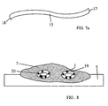
- FIG. 7 shows a cross section through a fiber 15, which fiber can be a plastic thread, a textile thread, a glass thread, or the like.
- a fiber 15 which fiber can be a plastic thread, a textile thread, a glass thread, or the like.
- the fiber cladding 14 has a different optical refractive power than, for example, the fiber 15 itself.
- the invention is not based on the integration of such pigment platelets 1 in such a fiber 15 is limited. It is in a further development of the invention suggested that instead of the pigment platelets, the laser dyes in molecular Distribution can be introduced directly into the material of the fiber 15. Instead of Pigment platelets 1 which are shown in FIG. 7 then occur directly before mentioned laser dyes 3 in molecular distribution. To now one corresponding resonance excitation of these laser dyes 3 in the fiber 15 7a ensure that the end faces 17, 18th this fiber 15 are mirrored. Now such a fiber 15 from the outside excited with a suitable radiation, then there is a pumping process between the end faces 17, 18 through the fiber 15, where now through the Laser dyes 3 arranged in molecular distribution directly for lighting up to be brought. Corresponding emitted laser radiation then occurs on the End faces 17, 18, as is known in a fiber laser.
- FIG. 8 shows the integration of a printing ink 7 on a paper 5, the aforementioned pigment platelets being arranged in so-called polymer sleeves 19.
- Pigment platelets are thus introduced into a matrix, a polymer shell 19, and this acts like a microencapsulation on the pigment platelets, which can thereby be integrated in the printing ink 7 at low cost.
- the polymer sleeve 19 can also serve as a carrier for an electroluminescent excitable pigment 20. This has the advantage that when the printing ink 7 is excited by means of a suitable laser radiation, the pigment platelets 1 first light up. If a pigment 20 that can be excited via electroluminescence or another security pigment is additionally used, then additional radiation can be generated which is superimposed on the other radiation.
- Such pigments 20 can, for example, be illuminated by a corresponding electrostatic field, and their radiation can be superimposed on the radiation emitted by the pigment platelets 1.
- the wavelength of the light emitted by the pigments 20 can shift due to the laser emission of the pigment platelets 1. This leads to an improved safety effect of this arrangement, because this mutually superimposing radiation is very difficult to imitate.
- a plastic card 21 is shown in the known manner when illuminated with daylight, which has a photo area 22 and a labeling field 23. If this plastic card 21 is irradiated with laser light, the appearance according to FIG. 10 results. The laser light is used to excite hidden features.
- a first security element 24 is present, which is applied into the inscription space via the photo surface 22. In the exemplary embodiment, it consists of three different sector colors 25, which complement each other to form a circle, which consequently only light up when excited with the aforementioned laser light.
- a window thread 10 is also shown, which extends through both the photo surface 22 and the labeling field 23 and other surfaces of the plastic card 21.
- This window thread can also have the aforementioned microtext; it can be designed to be illuminated.
- the printing thread 26 can not only consist of a metallized thread, but which is printed in the form of a print and extends over the image and the labeling field in order to make forgeries visible in these areas.
- another security element 27 is shown in the form of a geometric element, which, for. B. is suitable for machine evaluation.
- FIGS. 11 and 12 Another example of a personal document 28 is shown in FIGS. 11 and 12 differently concealed features. Again, it is one Photo area 22 and a labeling field 23 available. It can be seen in FIG. that two overlapping printing threads 26 are provided, both the Cover photo area 22 as well as labeling field 23. As another Example is the name of the holder of the personal document with a provided illuminating bar 29, which was overprinted with a printing ink, in which the pigment platelets 1 were distributed.
- a bank note 30 which has a certain number of known features when illuminated with daylight.
- the security feature 31 which lights up in different colors in the form of a rosette, has now been excited accordingly with the laser light.
- the value field 33 is overprinted with the same number but shifted to it, which lights up when excited with a laser of the appropriate color and energy. So this is also an additional security element.
- the laser dyes shown here show fluorescence in the UV range. If the pigment platelets 1 provided with the laser dyes are excited, then the previously described sharp emission lines in the emission spectrum occur due to the described resonance phenomena. Such an emission spectrum is now extremely suitable for machine evaluation of the authenticity features of such value and security documents.
- a number of security features can be queried and evaluated, such as B. Wavelength of the emitted radiation peaks, mutual position of the peaks, full width at half maximum, number of peaks and peak amplitude. These parameters depend on the laser color used, the excitation energy and the materials in which the laser color is embedded.
Abstract
Description
Die Erfindung betrifft ein Wert- und Sicherheitsdokument nach dem Oberbegriff
des Patentanspruchs 1.The invention relates to a value and security document according to the preamble
of
Die Erfindung geht von einem Stand der Technik aus, wie er beispielsweise in der US 4 738 901 beschrieben ist. Dort ist ein Wert- und Sicherheitsdokument in Form eines kopiergeschützten Papiers vorgesehen, in welches Phosphorpartikel eingebettet sind. Es handelt sich um einen Kopierschutz, denn mit dem den Kopierer zugeordneter Laser werden die Phosphorpartikel angeregt und die von den Phosphorpartikeln abgestrahlte Strahlung wird von einem zweiten Detektor aufgenommen, der demgemäß dem Kopiergerät mitteilt, daß es sich um ein geschütztes Dokument handelt. Eine Echtheitsprüfung eines derartigen Wert- und Sicherheitsdokumentes ist bei diesem Kopierschutzvorgang nicht vorgesehen und nicht möglich.The invention is based on a prior art, such as in the US 4,738,901. There is a value and security document in Form of copy-protected paper is provided, in which phosphor particles are embedded. It is a copy protection, because with that Copier-associated lasers excite the phosphor particles and those of Radiation emitted by the phosphor particles is emitted by a second detector added, which accordingly tells the copier that it is a protected document. An authenticity check of such a value and Security document is not provided for in this copy protection process and not possible.
Aufgabe der vorliegenden Erfindung ist es, eine Echtheitsprüfung von Wert- und Sicherheitsdokumenten mit optisch anregbaren Farbstoffen vorzuschlagen, bei der ein definiertes Emissionsspektrum des optisch angeregten Wert- und Sicherheitsdokumentes erfaßt werden kann und demzufolge ein charakteristisches Spektrum für dieses Wert- und Sicherheitsdokument erzeugt werden kann, welches charakteristisch ist sowohl für den in das Sicherheitsdokument eingebetteten Farbstoff als auch für das Material des Sicherheitsdokumentes selbst.The object of the present invention is to carry out an authenticity check of value and To propose security documents with optically stimulable dyes which is a defined emission spectrum of the optically excited value and Security document can be recorded and therefore a characteristic spectrum for this value and security document which is characteristic of both in the Security document embedded dye as well as for the material of the Security document itself.
Diese Aufgabe wird durch die kennzeichnenden Merkmale des Patentanspruchs 1
gelöst.This object is achieved by the characterizing features of
Die vorliegende Erfindung beruht darauf, daß das Einbringen bestimmter optisch anregbarer Farbstoffe in ein Sicherheitsdokument so erfolgt, daß bei der optischen Anregung des Wert- und Sicherheitsdokumentes die im Wert- und Sicherheitsdokument eingebetteten Farbstoffe in Resonanz mit dem Material des Wert- und Sicherheitsdokumentes gelangen, um so ein scharf definiertes Spektrum aller angeregten Materialien zu emittieren. The present invention is based on the fact that the introduction of certain optically stimulable dyes in a security document so that the optical excitation of the value and security document in the value and Security document embedded dyes in resonance with the material of the Value and security document to get a sharply defined To emit spectrum of all excited materials.
Es wird also eine Resonanz zwischen dem Material des Wert- und Sicherheitsdokumentes und dem dort eingebetteten Farbstoffen erzeugt, was zu einem genauen spezifizierten Emissionsspektrum führt, welches einerseits von dem Material des Dokumentes abhängig ist und andererseits von den eingebetteten Farbstoffen.So there will be a resonance between the material of the value and Security document and the dyes embedded there creates what to leads to a precisely specified emission spectrum, which on the one hand from depends on the material of the document and on the other hand on the embedded dyes.
Die Integration exklusiv entwickelter Laserfarbstoffe mit vorzugsweise nicht kommerziellen Anregungswellenlängen (UV bis IR) in Sicherheits- und Wertprodukte kann auf unterschiedliche Weise erfolgen. Prinzipiell ist eine Einbringung in das Substrat (z.B. Papier, Kunststoffolien), in Papierzusatzstoffen (z.B. Fasern, Planchetten), in Druckfarben und produktionstechnisch in Kombination mit anderen Sicherheitsmerkmalen (z.B. Fluoreszenz-, El-, Up-conversion- oder Phosphoreszenzpigmente, metallisierter Kunststoffstreifen, Hologrammen) möglich. Zum Einbringen der flüssigen Farbstoffmoleküle in eine feste Matrix (Granulat mit einer Größe im µm- bis nm-Bereich) und/oder zum Schutz der Farbstoffe vor UV-Licht, Lösungsmittel oder sonstigen Reagenzstoffen ist je nach Anwendung eine geeignete, z.B. UV-absorbierende Schutzhülle notwendig. Im günstigsten Fall können die Laserfarbstoffe direkt in einen Farbbestandteil (Harze oder Pigmente) integriert werden. Bei Anwendungen im Karten-/Folienbereich können die unverkapselten oder verkapselten Farbstoffe direkt in die Polymermatrix eingerührt und fixiert werden. Unter dem Begriff Laserfarbstoff wird verstanden ein durch Laserstrahl anregbares, sehr hoch effizient fluoreszierendes Material in jedem beliebigen Aggregatzustand, d. h. fest flüssig oder gasförmig.The integration of exclusively developed laser dyes with preferably not commercial excitation wavelengths (UV to IR) in safety and Valuable products can be made in different ways. In principle there is one Incorporation into the substrate (e.g. paper, plastic films), in paper additives (e.g. fibers, planchettes), in printing inks and in production technology Combination with other security features (e.g. fluorescent, EL, up-conversion or phosphorescent pigments, metallized plastic strips, Holograms) possible. For introducing the liquid dye molecules into a solid matrix (granules with a size in the µm to nm range) and / or Protection of the dyes against UV light, solvents or other reagents is a suitable one depending on the application, e.g. UV-absorbing protective cover necessary. In the best case, the laser dyes can be directly in one Color component (resins or pigments) can be integrated. For applications in Card / film area can contain the unencapsulated or encapsulated dyes are stirred directly into the polymer matrix and fixed. Under the term Laser dye is understood to be a very high excitable by laser beam efficiently fluorescent material in any physical state, d. H. firmly liquid or gaseous.
Ein Vorteil von Laserfarbstoffen im Vergleich zu Fluoreszenzstoffen sind scharfe
Emissionspeaks bei definierten Emissionswellenlängen über den gesamten
Fluoreszenzbereich der Laserfarbstoffe. Die ![]()
![]()
Neben der Einbringung der Laserfarbstoffe in einen Resonator, ist eine resonatorfreie Einbringung der Farbstoffe auf Kosten der Emissionsintensitäten in Wert- und Sicherheitsdokumente möglich. In addition to introducing the laser dyes into a resonator, one is resonator-free introduction of the dyes at the expense of the emission intensities in Valuable and security documents possible.
Die Emissionsintensität läßt sich durch Einbau der Laserfarbstoffe in einen Resonator erhöhen. Dazu ist eine beidseitige Beschichtung der Laserfarbstoff enthaltenden Polymerschichten mit metallischen oder dielektrischen Schichten mit einem höheren Brechungsindex notwendig. Neben der Strahlungsintensität wird damit auch die Sicherheit wesentlich erhöht, denn über die Geometrie und optischen Eigenschaften des Resonators läßt sich die Peakanzahl sowie deren Position im Wellenlängenbereich der Fluoreszenz einstellen. Zusätzlich läßt sich auch die Peakbreite durch die verwendete Geometrie einstellen.The emission intensity can be reduced by installing the laser dyes in one Increase the resonator. For this purpose, the laser dye is coated on both sides containing polymer layers with metallic or dielectric layers a higher refractive index is necessary. In addition to the radiation intensity this also significantly increases security, because of the geometry and optical properties of the resonator, the number of peaks and their Set position in the wavelength range of fluorescence. In addition, also set the peak width using the geometry used.
In einer ersten Ausführungsform ist vorgesehen, die Farbstoffe direkt in eine Schicht und/oder Drucklage des Wert- und Sicherheitsdokuments einzubringen, wobei die reflektierenden und/oder dielektrischen Schichten Teile des Wert- und Sicherheitsdokuments darstellen. Es bildet sich dadurch ein laseraktives Element, d.h. ein Resonator, der charakteristisch auf eine Anregung mit Laserlicht oder einem anderen, hochenergetischen Licht reagiert.In a first embodiment it is provided that the dyes directly into a To bring in the layer and / or print position of the value and security document, wherein the reflective and / or dielectric layers are parts of the value and Represent security document. This creates a laser-active element i.e. a resonator that is characteristic of excitation with laser light or another high-energy light.
In einer weiteren Ausführungsform ist vorgesehen, daß das laseraktive Element
nicht als ein Teil des Schichtaufbaus des Wert- und Sicherheitsdokuments
ausgebildet ist, sondern daß die laseraktiven Elemente in Form von
eigenständigen Resonatoren separat vom Wert- und Sicherheitsdokument
hergestellt werden und erst dann in Form von Pigment-Plättchen, -Stäbchen oder
-Kugeln, deren Grösse z.B. einige um beträgt, in das Dokument eingebracht oder
auf diesem aufgebracht werden.
Die Herstellung solcher Resonatoren für Anwendungen in
Sicherheitsdruckprodukten ist z.B. mittels Dünnschicht-Technologie machbar.
Nach dem Abscheiden der einzelnen, µm-dicken Schichten, d.h. mindestens einer
reflektierenden Schicht, einer Schicht mit Farbstoffen und einer weiteren,
reflektierenden Schicht, auf einem Foliensubstrat wird der Schichtverbund z.B.
durch Brechen zerkleinert. Die auf diese Weise erhaltenen, flächenförmigen
Bruchstücke die im weiteren auch als Flakes oder Pigment-Plättchen bezeichnet
werden, mit einer Dicke von 1 - 10 µm und einer Fläche < 20 x 20 µm2, können
dann je nach Größe in entsprechende Druckfarben (z.B. Stahlstich, Siebdruck,
Offset, Buchdruck) oder in das Papier und Folienmaterial des
Sicherheitsdokumentes integriert werden. In a further embodiment it is provided that the laser-active element is not formed as part of the layer structure of the value and security document, but that the laser-active elements are produced separately from the value and security document in the form of independent resonators and only then in the form of pigment Platelets, chopsticks or spheres, the size of which is, for example, a few μm, are introduced into or placed on the document.
The production of such resonators for applications in security printing products is feasible, for example, using thin-film technology. After the individual, μm-thick layers, ie at least one reflective layer, one layer with dyes and a further, reflective layer, have been deposited on a film substrate, the layer composite is comminuted, for example by breaking. The sheet-like fragments obtained in this way, which are also referred to below as flakes or pigment platelets, with a thickness of 1 - 10 µm and an area <20 x 20 µm 2, can then, depending on their size , be printed in appropriate inks (e.g. steel engraving , Screen printing, offset, letterpress) or be integrated into the paper and foil material of the security document.
Die Verwendung geometrisch unterschiedlicher Resonatoren führt zu einem
charakteristischen, äußerst schwierig nachstellbaren Peakmuster (Fingerprint) der
verwendeten "Mischung". Auch die Schwellenenergie (minimale Energie für die
Anregung einer Laseremission) wäre neben der nicht kommerziellen
Anregungswellenlänge ein weiterer Sicherheitsparameter zur Verifizierung
solcher Sicherheitsmerkmale. Laserfarbstoffe ließen sich als verstecktes oder
zweistufiges, mit UV-Licht kontrollierbares Sicherheitsmerkmal einsetzen, denn
alle Laserfarbstoffe zeigen wie bereits erwähnt eine breitbandige UV-Fluoreszenz.
In den folgenden Abschnitten werden Möglichkeiten der Einbringung der
Laserfarbstoffe in unterschiedliche Komponenten von Sicherheits- und
Wertprodukten beschrieben.The use of geometrically different resonators leads to a characteristic, extremely difficult to adjust peak pattern (fingerprint) of the "mixture" used. In addition to the non-commercial excitation wavelength, the threshold energy (minimum energy for the excitation of a laser emission) would also be a further security parameter for verifying such security features. Laser dyes can be used as a hidden or two-stage security feature that can be controlled with UV light, because, as already mentioned, all laser dyes show broadband UV fluorescence.
The following sections describe ways of incorporating laser dyes into different components of security and value products.
Die Einbringung von polymergebundenen Laserfarbstoffen in das Papier kann entweder durch direkte Zugabe der gebundenen Farbstoffe zur Rohstoffmischung oder durch Aufbringen auf das Papier nach dem Trocknen mittels Siebdruck erfolgen. Die direkte Zugabe hat den wirtschaftlichen Nachteil, daß große Mengen für eine ausreichende Leuchtdichte zugegeben werden müssen. Ein nachträgliches Aufbringen auf das Papier durch Bedrucken mittels Siebdruck benötigt wesentlich geringere Mengen an Laserfarbstoffen und ermöglicht zusätzlich eine Strukturierung im Sinne eines Wasserzeichens. Bei transparenten, farblosen Laserfarbstoffen könnten dadurch "versteckte Wasserzeichen" in das Papier eingebracht werden. Bei einer Verwendung unterschiedlicher Laserfarbstoffe ließen sich versteckte, farbige Wasserzeichen herstellen.The incorporation of polymer-bound laser dyes into the paper can either by directly adding the bound dyes to the raw material mixture or by screen printing after drying respectively. The direct addition has the economic disadvantage that large Amounts for sufficient luminance must be added. On subsequent application to the paper by screen printing requires much smaller amounts of laser dyes and enables additionally a structuring in the sense of a watermark. At transparent, colorless laser dyes could be "hidden" Watermark "can be introduced into the paper. When used different laser dyes made hidden, colored watermarks produce.
Im Vergleich zur direkten Einbringung in oder auf das Papier kann für den Kartenbereich eine sehr dünne Kunststoffolie mit den Laserfarbstoffen "dotiert" oder bedruckt werden. Durch den spezifischen Kartenaufbau, läßt sich die mit Laserfarbstoffen versehene Folie in die Mitte des Laminatverbundes einbringen. Dies führt zu einem chemisch-physikalischen Schutz der Farbstoffe vor Umwelteinflüssen, z.B. UV-Licht und zu einer höheren Sicherheit durch den engen Materialverbund zwischen Laserfarbstoff und Polymerschicht.In comparison to the direct insertion into or onto the paper, the Card area a very thin plastic film "doped" with the laser dyes or printed. Due to the specific map structure, it can be used with Insert the foil provided with laser dyes in the middle of the laminate composite. This leads to chemical-physical protection of the dyes Environmental influences, e.g. UV light and for a higher security through the close material bond between laser dye and polymer layer.
Eine weitere Möglichkeit zur Integration der Laserfarbstoffe ist die Kombination mit sogenannten Zusatzstoffen, wie z.B. Kunststoffäden, Fasern oder Planchetten. Kunststoffäden werden teilmetallisiert als Fensterfaden in Wert- und Sicherheitspapier bei der Herstellung eingebracht. Zur Erhöhung der Sicherheit sind diese Fensterfäden noch mit einer Mikroschrift versehen. Die Herstellung der Mikroschrift kann chemisch (Ätzen) oder physikalisch (Laserabtragung) erfolgen. Die freigelegten Stellen erscheinen als Fenster. Die Verbindung zu Laserfarbstoffen könnte in diesem Fall wieder über die Kunststoffphase erfolgen. Die Laserfarbstoffe lassen sich wie bereits erwähnt einfach in die Kunstoffmatrix integrieren. Bei einer Anregung von oben, unten oder der Seite mittels einem geeigneten Laserlicht würde dann die Mikroschrift je nach gewählten Laserfarbstoff, z.B. blau aufleuchten. Ähnlich wie die Fensterfäden könnten auch Faser oder Planchetten mit Laserfarbstoffen versehen werden. Bei Fasern bestehen die Möglichkeiten die Laserfarbstoffe in das Fasermaterial einzubringen, die Fasern bei der Verwendung von Hohlraumfasern (di > 10 µm) zu füllen oder eine mit Laserfarbstoffen dotierte. Polymermatrix als Umhüllung (d < 2 µm) der Fasern zu verwenden. Planchetten lassen sich ähnlich wie Fasern überziehen oder dotieren.Another possibility for integrating the laser dyes is the combination with so-called additives, such as plastic threads, fibers or planchettes. Plastic threads are partially metallized as window threads in security and security paper during manufacture. To increase security, these window threads are also provided with a micro script. The micro script can be produced chemically (etching) or physically (laser ablation). The exposed areas appear as windows. In this case, the connection to laser dyes could again be made via the plastic phase. As already mentioned, the laser dyes can be easily integrated into the plastic matrix. In the case of excitation from above, below or from the side by means of a suitable laser light, the micro-writing would then light up, for example blue, depending on the laser dye selected. Similar to the window threads, fibers or planchettes could also be provided with laser dyes. In the case of fibers, there are options for introducing the laser dyes into the fiber material, filling the fibers when using hollow fibers (d i > 10 µm) or one doped with laser dyes. To use polymer matrix as a covering (d <2 µm) of the fibers. Planchettes can be coated or doped in a similar way to fibers.
Bei der Einbringung der derartiger Laserfarbstoffe in Kunststoffäden, Glasfasern und anderen transparenten Fasern, insbesondere auch Textilfasern, besteht der Vorteil, daß man praktisch damit schon eine Art Laser-Resonator erzeugt. Wenn man nämlich sich vorstellt, daß ein Kunststoffaden mit begrenzter Länge an den beiden Stirnseiten verspiegelt ist und dieser mit einem Laser angeregt wird. Dann kommt es zu einer Resonanzerscheinung, d. h. dieser Kunststoffaden selbst wirkt als Laser, weil die eingestrahlte Strahlung zu einer stimulierten Emission längs der Faser führt. Wie bei den schon beschriebenen Plättchen bestimmt die Länge der Faser sowie die Reflexion an den Faserenden die Peaklage und die Halbwertsbreite der Emissionspeaks. Hierbei ist es nicht einmal erforderlich, daß die Stirnseiten verspiegelt werden; es reichen auch unverspiegelte Stirnseiten aus. Voraussetzung hierfür ist, daß der Farbstoff, der in dem Kunststoffaden eingebettet ist, ausreichend effizient ist. Selbstverständlich ist diese Erkenntnis nicht auf die Verwendung von Kunststoffäden allein beschränkt, es können also beliebige Fasern verwendet werden. Hieraus ergibt sich aber das allgemeine Funktionsprinzip der Erfindung, d. h. also auf die allgemeine Einbettung derartiger laseranregbarer Farbstoffe in dem Wert- und Sicherheitsdokument, mit dem Ziel eine entsprechende Resonanz zu erzeugen, um scharfbandige Peaks zu ermöglichen.When introducing such laser dyes into plastic threads, glass fibers and other transparent fibers, especially textile fibers, consists of The advantage that practically a kind of laser resonator is generated with it. If one imagines that a plastic thread of limited length to the is mirrored on both ends and this is excited with a laser. Then there is a resonance phenomenon, d. H. this plastic store itself works as a laser, because the irradiated radiation along to a stimulated emission the fiber leads. As with the tiles already described, the length determines the peak as well as the reflection at the fiber ends Half-width of the emission peaks. It is not even necessary that the end faces are mirrored; non-mirrored end faces are also sufficient out. The prerequisite for this is that the dye in the plastic store is embedded, is sufficiently efficient. This is a matter of course not limited to the use of plastic threads alone, so it can any fibers can be used. But this gives the general Operating principle of the invention, d. H. so on the general embedding of such laser-excitable dyes in the value and security document, with the aim generate an appropriate resonance to produce sharp-banded peaks enable.
Die vorliegende Erfindung ist im übrigen nicht auf die Anregung mittels eines Lasers beschränkt; es können auch andere energiereiche optische Angregungsmedien verwendet werden, wie z. B. eine Blitzlampe, Natrium- oder Hochdrucklampen und dergleichen mehr. Ebenso ist auch eine Anregung mittels Lumineszenzdioden nicht nur im sichtbaren, sondern auch im unsichtbaren Wellenlängenbereich möglich.The present invention is not based on the excitation by means of a Lasers limited; other high-energy optical systems can also be used Excitation media are used, such as. B. a flash lamp, sodium or High pressure lamps and the like. A suggestion is also possible Luminescent diodes not only in the visible, but also in the invisible Wavelength range possible.
Der Haupteinsatz von Laserfarbstoffen in Wert- und Sicherheitsprodukten liegt in der direkten Einbringung in eine Druckfarbe. Dazu zählen Stahlstich-, Siebdruck- und Offsetfarben (Naß-, Trockenoffset und indirekter Hochdruck) sowie Farben für den Buchdruck (Nummerierung) und sonstige für den Wert- und Sicherheitsdruck relevanten Druckverfahren. Für jede dieser Farben ist eine individuelle Anpassung zwischen Druckfarbe und zuzugebenden Laserfarbstoffen, sei es in Molekülform oder als eine Feststoffmatrix, notwendig. Bei einer Verwendung von Resonatoren sind zusätzlich noch deren Form (i.d.R. Plättchen aber auch Kugeln) und Größe für die Übertragen von der Farbe auf den Druckstoff maßgebend. Während im Stahlstich und Siebdruck allgemein Farbstoffpigmente bis zu einer Größe von 20 µm unproblematisch verdruckt werden können, gibt es im Offset eine Obergrenze von 2 bis 4 µ. Die Form (Plättchen oder Kugeln) hat u.a. einen Einfluß auf den Herstellungsaufwand, die Einmischbarkeit in die Druckfarbe (Reibstuhl) die Stabilität, die Lichtsausbeute und die spektrale Verteilung/Linienform. Kugelförmige Gebilde sind einfacher herzustellen und sind mechanischer stabiler. Dies geht auf Kosten einer schlechteren Verarbeitungseigenschaft und geringeren Resonatoreffizenz. Die Herstellung von Plättchen ist technisch aufwendig und teuer, führt aber i.d.R. zu einer höheren Lichtausbeute sowie zu definierten, einstellbaren Peakmustern. Ferner erlaubt die Verwendung von Plättchen die Ausnutzung der Strahlungsgeometrie, man bekommt eine anisotrope Strahlung. Somit ließe sich theoretisch bei einem dünnen Farbauftrag, wie beim Offsetdruck, eine hohe Emissionsintensität erreichen. Im allgemein reduzieren sich die optischen Effekte mit Abnahme der aktiven Schichtdicke (Stahlstich bis 20 µm, Offset 1 bis 4 µm). Auf Grund der Farbbestandteile von Druckfarben ist es auch denkbar die Farbstofflösungen direkt in ein Bestandteil der Farbe zu integrieren. Eine Möglichkeit dazu bieten z.B. die Harzbestandteile (Kolophonium) von hochviskosen Stahlstichfarben oder eine Kombination mit bereits vorhandenen Farb- oder Effektpigmenten durch gemeinsame Verkapselung. Druckfarben an sich stellen ein Stabilisator für unverkapselte Laserfarbstofflösungen dar. Im Hinblick auf die Farbabstimmung und den Effekt sollten die Farben, welche als Trägermedien für die Laserfarbstoffe dienen keine stark deckende Eigenschaften haben und nach Möglichkeit transparent sein. Die Einbringung der gelösten oder gebundenen Laserfarbstoffe in die Druckfarben sollte durch direkt Zugabe zur Farbmischung, bestehend aus Lösungsmittel, Pigmenten und Zusatzstoffen möglich sein. Auf Grund des starken Effektes sind Konzentrationen im sub%-Bereich ausreichend und aus Gründen der Wirtschaftlichkeit als Obergrenze anzusehen.The main use of laser dyes in valuable and security products is in direct insertion into a printing ink. These include steel engraving, screen printing and Offset inks (wet, dry offset and indirect letterpress printing) as well as inks for letterpress printing (numbering) and other for value and Security printing relevant printing process. There is one for each of these colors individual adjustment between printing ink and to be added Laser dyes, whether in molecular form or as a solid matrix, are necessary. If resonators are used, their shape (usually Platelets but also balls) and size for the transfer from the color to the Decisive material. While in steel engraving and screen printing in general Dye pigments up to a size of 20 µm printed without problems there is an upper limit of 2 to 4 µ in the offset. Form (Tiles or balls) has an impact on manufacturing costs, the Can be mixed into the printing ink (rubbing chair), the stability, the light output and the spectral distribution / line shape. Spherical structures are simpler manufacture and are mechanically more stable. This is at the expense of one poorer processing properties and lower resonator efficiency. The The production of platelets is technically complex and expensive, but usually leads to to a higher luminous efficacy as well as defined, adjustable peak patterns. Furthermore, the use of tiles allows the use of the Radiation geometry, you get anisotropic radiation. So you could theoretically a high one with a thin ink application, like with offset printing Achieve emission intensity. In general, the optical effects are reduced with a decrease in the active layer thickness (steel engraving up to 20 µm, offset 1 to 4 µm). Due to the color components of printing inks, it is also conceivable Integrate dye solutions directly into a component of the color. A Offer the opportunity to do this e.g. the resin components (rosin) of highly viscous steel engraving colors or a combination with existing ones Color or effect pigments through joint encapsulation. Inks are a stabilizer for unencapsulated laser dye solutions. In With regard to the color matching and the effect, the colors, which as Carrier media for the laser dyes do not have strong covering properties have and if possible be transparent. Introducing the solved or Bound laser dyes in the printing inks should be added directly to the Color mixture consisting of solvents, pigments and additives to be possible. Due to the strong effect, concentrations are in the sub% range sufficient and for reasons of economy as an upper limit to watch.
Neben der Einbringung der Laserfarbstoffe in die Ausgangsprodukte ist auch die Kombination mit anderen Sicherheitsmerkmal, sei es als verstecktes Merkmal zur Erhöhung der Absicherung, als Anregungsquelle für Sekundäreffekte z.B. UV-Fluoreszenz oder Phosphoreszenz, als Hintergrundbeleuchtung von Hologrammen oder sonstigen Beugungsstrukturen und als Ergänzung von Information bei denen ohne Laseranregung nur ein Teil der versteckten Information mir einem Hilfsmittel (z.B. Linsenraster) sichtbar wird denkbar. Die Kombination von Laserfarbstoffen mit Fluoreszenzfasern, Planchetten und Fensterfäden wurde bereits oben beschrieben. Eine weitere interessante Variante wäre die Kombination mit Elektrolumineszenz (EL) -Pigmenten. Die Umhüllung von anorganischen. EL-Pigmenten mit einer Laserfarbstoff-dotierten Polymerephase nahezu nicht nachstellbares Sicherheitsmerkmal mit unterschiedlichsten Verifikationsstufen. Eine UV-Anregung würde eine Mischfluoreszenz bestehend aus Anteilen von EL-Pigmenten sowie aus Anteilen der Laserfarbstoffen erzeugen, eine Anregung mittels einem geeigneten Laserstrahl würde voraussichtlich nur die Laserfarbstoffe anregen, da für eine Anregung von EL-Pigmenten mittels eines gepulsten Laserstrahls der elektrische Feldanteil des Laserlichtes nicht geeignetist, und schließlich würde eine elektrischen Anregung die EL-Pigmente zum Leuchten bringen. Neben den einzelnen Effekten besteht sicherlich auch eine Wechselwirkung, bzw. gegenseitige Beeinflussung der Effekte, da die gleichzeitige Einwirkung verschiedener Anregungsquellen die Bandstruktur der vorliegenden Materialien und damit die Auswirkungen beeinflussen. In addition to the incorporation of laser dyes into the starting products, there is also Combination with other security feature, be it as a hidden feature Increased protection, as a source of excitation for secondary effects e.g. UV fluorescence or phosphorescence, as backlighting from Holograms or other diffraction structures and as a supplement to Information where only part of the hidden ones without laser excitation Information with a tool (e.g. lenticular grid) is conceivable. The Combination of laser dyes with fluorescent fibers, planchettes and Window threads have already been described above. Another interesting variant would be the combination with electroluminescent (EL) pigments. The wrapping of inorganic. EL pigments doped with a laser dye Polymer phase with almost non-adjustable security feature different verification levels. UV excitation would be one Mixed fluorescence consisting of portions of EL pigments as well as portions of the laser dyes generate an excitation by means of a suitable one Laser beam would probably only excite the laser dyes, as for one Excitation of EL pigments using a pulsed laser beam Field portion of the laser light is unsuitable, and eventually one would electrical excitation to make the EL pigments glow. In addition to the there is certainly an interaction of individual effects, or mutual influence of the effects, since the simultaneous action different sources of excitation the band structure of the available materials and thus affect the impact.
Der Erfindungsgegenstand der vorliegenden Erfindung ergibt sich nicht nur aus
dem Gegenstand der einzelnen Patentansprüche, sondern auch aus der
Kombination der einzelnen Patentansprüche untereinander.
Alle in den Unterlagen, einschließlich der Zusammenfassung, offenbarten
Angaben und Merkmale, insbesondere die in den Zeichnungen dargestellte
räumliche Ausbildung werden als erfindungswesentlich beansprucht, soweit sie
einzeln oder in Kombination gegenüber dem Stand der Technik neu sind.The subject matter of the present invention results not only from the subject matter of the individual patent claims, but also from the combination of the individual patent claims with one another.
All of the information and features disclosed in the documents, including the summary, in particular the spatial design shown in the drawings are claimed to be essential to the invention, insofar as they are new to the prior art, individually or in combination.
Im folgenden wird die Erfindung anhand von mehrere Ausführungswege
darstellenden Zeichnungen näher erläutert. Hierbei gehen aus den Zeichnungen
und ihrer Beschreibung weitere erfindungswesentliche Merkmale und Vorteile der
Erfindung hervor.
Prinzipiell gibt es für die Verwendung im Wert- und Sicherheitsdruck keine
Einschränkung bezüglich der Verwendung. Als Beispiele sind Vorschläge für die
Integration von Laserfarbstoffen in Kunststoffkarten (Ausweiskarte, EU-Führerschein,
Kreditkarten) Ausweise und Banknoten aufgeführt.In the following, the invention is explained in more detail with reference to drawings showing several possible embodiments. Further features and advantages of the invention which are essential to the invention emerge from the drawings and their description.
In principle, there are no restrictions on use for security and security printing. As examples, suggestions for the integration of laser dyes in plastic cards (ID card, EU driver's license, credit cards) ID cards and banknotes are listed.
Es zeigen:
- Figur 1:
- schematisiert ein grundsätzlicher Aufbau eines Pigment-Plättchens, welche in ein nicht näher dargestelltes Wert- und Sicherheitsdokument eingebettet ist, oder welches in eine entsprechende Farbe eingebettet ist, die auf dem Wert- oder Sicherheitsdokument aufgedruckt oder angebracht ist;
- Figur 2:
- zeigt die Einbringung derartiger Pigment-
Plättchen nach Figur 1 in ein Papier; - Figur 3:
- zeigt die Einbringung derartiger Pigment-Plättchen in eine Kunststoffolie;
- Figur 4:
- zeigt die Einbringung derartiger Pigment-Plättchen in eine Farbe zum Bedrucken von Papier- oder Kunststoffolien;
- Figur 5:
- zeigt einen laseranregbaren Fensterfaden in einem Wert- und Sicherheitsdokument;
- Figur 6:
- schematisiert einen Schnitt durch das
Dokument nach Figur 5; - Figur 7:
- Querschnitt durch eine Faser mit Einbringung der Pigment-Plättchen;
- Figur 8:
- der Querschnitt durch den oberen Teil eines Wert- oder Sicherheitsdokumentes mit in eine Druckfarbe eingebrachten Pigment-Plättchen;
- Figur 9:
- die Anwendung der erfindungsgemäßen Technik bei einer Kunststoffkarte mit Beleuchtung bei Tageslicht;
- Figur 10:
- die gleiche
Darstellung wie Figur 9 bei Beleuchtung mit Laserlicht; - Figur 11:
- Darstellung eines Personaldokumentes bei Beleuchtung mit Tageslicht;
- Figur 12:
- Die gleiche Darstellung des Dokumentes bei Beleuchtung mit Laserlicht;
- Figur 13:
- Eine Banknote bei Beleuchtung mit Tageslicht;
- Figur 14:
- Die Beleuchtung der gleichen Banknote mit Laserlicht;
- Figure 1:
- schematized a basic structure of a pigment plate, which is embedded in a value and security document, not shown, or which is embedded in a corresponding color, which is printed or attached to the value or security document;
- Figure 2:
- shows the introduction of such pigment flakes according to Figure 1 in a paper;
- Figure 3:
- shows the introduction of such pigment platelets in a plastic film;
- Figure 4:
- shows the introduction of such pigment platelets in a color for printing on paper or plastic films;
- Figure 5:
- shows a laser-excitable window thread in a value and security document;
- Figure 6:
- schematized a section through the document of Figure 5;
- Figure 7:
- Cross section through a fiber with the introduction of the pigment platelets;
- Figure 8:
- the cross section through the upper part of a value or security document with pigment plates inserted into a printing ink;
- Figure 9:
- the application of the technology according to the invention in a plastic card with illumination in daylight;
- Figure 10:
- the same representation as Figure 9 when illuminated with laser light;
- Figure 11:
- Presentation of a personal document when illuminated with daylight;
- Figure 12:
- The same representation of the document when illuminated with laser light;
- Figure 13:
- A banknote when lit by daylight;
- Figure 14:
- Illuminating the same banknote with laser light;
In Figur 1 ist allgemein ein Pigment-Plättchen 1 dargestellt, welches aus zwei im
wesentlichen parallel zueinander liegenden und einen gegenseitigen Abstand
einnehmenden, reflektierenden Schichten 2 besteht, die auf einer Polymerschicht
4 aufgebracht sind. Die reflektierenden Schichten 2 bestehen hierbei aus einer
Oxid-Schicht, z. B. Siliziumioxid, Silziumliquid, Zinnoxid, Titanoxid und
dergleichen mehr. Es kann aber auch eine metallische Schicht sein. Wesentlich
ist nur, daß zwei reflektierende Schichten 2 einander gegenüber liegen, die so zu
sagen als Spiegel zwischen sich die Polymerschicht aufnehmen und in der
Polymerschicht 4 die Laserfarbstoffe 3 eingebettet sind.
Zusätzlich kann es vorgesehen sein, daß gemäß Figur 1 auch die Stirnseiten des
Pigment-Plättchens 1 mit den reflektierenden Schichten 2 versehen sind.FIG. 1 generally shows a
In addition, it can be provided that, according to FIG. 1, the end faces of the
Die Polymerschicht 4 besteht aus einem Kunststoffpolymer. Anstelle einer
Polymerschicht kann aber auch eine Glasschicht verwendet werden oder ein
anderer durchsichtiger Träger, der sowohl transparent für die anregende
Wellenlänge als auch transparent für die emittierende Wellenlänge sein muß. Es
ist also nicht lösungsnotwendig, eine Polymerschicht 4 zu verwenden, sondern es
können beliebige transparente Trägerschichten verwendet werden. Hierbei ist es
nicht notwendig, daß sie im sichtbaren Licht transparent sind, sondern sie können
auch im unsichtbaren Licht transparent sein.
Es kann auch in einer anderen Ausführungsform die oben genannten elektrischen
Schichten entfallen und nur reflektierende Schichten an den Stirnflächen
vorhanden sein. The polymer layer 4 consists of a plastic polymer. Instead of a polymer layer, however, a glass layer or another transparent support can be used, which must be both transparent to the exciting wavelength and transparent to the emitting wavelength. It is therefore not necessary to use a polymer layer 4, but any transparent carrier layers can be used. It is not necessary that they be transparent in visible light, but that they can also be transparent in invisible light.
In another embodiment, the electrical layers mentioned above can also be omitted and only reflecting layers can be present on the end faces.
Für die verwendeten Laserfarbstoffe 3, die in molekularer Korngröße vorliegen
können eine Vielzahl von Stoffen verwendet werden.
Solche Farbstoff-Lasersysteme wurden bereits auf der Basis von
Dünnschichtsystemen (DCM-dotierte Polymerwellenleiter) und ASPT-dotierte
Polymerstäbe verifiziert [J. D. Bhawalkar, et al., Opitcs Communication 124,
1996,33]. Es kann z.B. auch Rhodamin 6G verwendet werden.A large number of substances can be used for the laser dyes 3 which are present in molecular grain size.
Such dye laser systems have already been verified on the basis of thin-layer systems (DCM-doped polymer waveguides) and ASPT-doped polymer rods [JD Bhawalkar, et al., Opitcs Communication 124, 1996, 33]. For example, Rhodamine 6G can also be used.
Aus wirtschaftlichen Gründen wird eine relativ geringe Konzentration der Laserfarbstoffpartikel 3 in der Polymerschicht 4 angestrebt. Hierauf ist die Erfindung jedoch nicht beschränkt; sie kann auch vorsehen, daß derartige partikelförmig und molekular vorliegende Laserfarbstoffe 3 clusterförmig vorliegen oder in der Dichte sehr stark unterschiedlich in der Polymerschicht 4 verteilt sind. Eine gleichmäßige Dichteverteilung ist deshalb nicht lösungsnotwendig.For economic reasons, a relatively low concentration of the Laser dye particles 3 aimed in the polymer layer 4. This is the However, the invention is not limited; it can also provide that such Particulate and molecular laser dyes 3 are clustered or are distributed very differently in the density in the polymer layer 4. A uniform density distribution is therefore not necessary for the solution.
Das Beispiel nach Figur 1, mit einem als Pigment-Plättchen 1 eingesetzten
Farbstoff 3 ist nicht beschränkend für die vorliegende Erfindung. Es kann nämlich
anstatt des hier dargestellten Pigment-Plättchens mit den zwei aneinander
gegenüber liegenden und reflektierenden Schichten 2 auch ein
Sicherheitsdokument verwendet werden, welches diese Pigment-Plättchen 1 nicht
beinhaltet. Die beiden reflektierenden Schichten wären dann direkt im
Sicherheitsdokument im gegenseitigen Abstand parallel zueinander integriert und
zwischen den beiden reflektierenden Schichten ist dann die mit
Laserfarbstoffmolekülen dotierte Trägerschicht, z.B. eine Polymerschicht,
angeordnet. Es ergibt sich dann eine laseraktives Element bzw. ein laseraktiver
Bereich auf dem Sicherheitsdokument, der aus der- zwischen den beiden
reflektierenden Schichten eingebetteten und mit Laserfarbstoff dotierten
Trägerschicht besteht. Das heißt also, die Darstellung nach Figur 1 kann auch um
das Zehntausendfache vergrößert direkt als schichtweise aufgebautet Dokument
angesehen werden.The example according to FIG. 1, with one used as
Hieraus ergibt sich, daß die Erfindung nicht auf die Einbringung von Pigment-Plättchen
1 nach Figur 1 in unterschiedliche Wert- und Sicherheitsdokumente
beschränkt ist, sondern daß Wert- und Sicherheitsdokument ansich kann
derartige reflektierende Schichten aufweisen, zwischen denen eine transparente
Polymerschicht angeordnet ist, die mit dem besagten molekular vorliegenden
Laserfarbstoffen dotiert ist. It follows that the invention is not based on the introduction of
In Figur 2 zeigt ein Papier 5, in dem die Pigment-Plättchen nach Figur 1
eingebaut und verteilt sind. Für die Verteilung der Pigment-Plättchen im Papier 5
gilt das gleiche, wie es vorstehend für die Verteilung der Laserfarbstoffe 3 in der
Polymerschicht 4 gesagt wurde. Es ist nicht lösungsnotwendig, daß die Pigment-Plättchen
in relativ dünner Verteilung in dem Papier angeordnet sind. Sie können
auch Cluster bilden; sie können auch an der Oberfläche verteilt sein oder sie
können auch dicht bei einander liegen. In Bereichen wo sich die Flakes
überlagern, kann es zu einer Behinderung der eingestrahlten Strahlung kommen,
da sich die Pigment-Plättchen teilweise abdecken und hierdurch die Anregung
abgeschwächt wird. Es gibt dann Interferenzeffekte, welche die emittierte
Strahlung abschwächen. Es sollte eine derartige Verteilung im Papier gewählt
werden, daß sich die Pigment-Plättchen nicht gegenseitig überlagern und stören.2 shows a
Die Figur 3 zeigt eine ähnliche Darstellung, wo erkennbar ist, daß die Pigment-Plättchen
1 in einer Kunststoffolie 6 eingebettet sind. Die Kunststoffolie kann
hierbei eine beliebige Dicke aufweisen.Figure 3 shows a similar representation where it can be seen that the
Die Figur 4 zeigt, daß eine Druckfarbe 7 auf einem Träger 8 angeordnet ist, wobei
dieser Träger 8 ein Wert- und Sicherheitsdokument sein kann. In der Druckfarbe
7 sind die Pigment-Plättchen 1 eingebettet. Die Druckfarbe 7 selbst sollte an das
emittierte Spektrum der Pigment-Plättchen 1 angepaßt sein, um eine
ausreichende Emissionsstrahlung zu erreichen. Ebenso muß die Druckfarbe
transparent für die anregende als auch die abgegebene Strahlung sein, um
überhaupt eine Anregung der Pigment-Plättchen 1 zu gewährleisten.Figure 4 shows that a
Die Figur 5 zeigt als weiteres Ausführungsbeispiel die Integration eines
Fensterfadens in einem Wert- und Sicherheitsdokument 9. Es handelt sich hierbei
um einen Fensterfaden 10, der in Ansicht bekannter Weise in dem Wert- und
Sicherheitsdokument 9 integriert ist, wobei die Figur 5a zeigt, daß der
Fensterfaden 10 im Bereich der Beschriftung 11 ausgespart ist, und/oder
napfförmige Vertiefungen aufweist oder Aussparungen aufweist, die mit dem
Laserfarbstoff gefüllt sind. Das heißt also, es findet eine Farbe Anwendung, die
mit dem Pigment-Plättchen 1 dotiert ist. Wird der Fensterfaden 10 nun mit dem
entsprechenden Licht angeregt, dann kommt diese Druckfarbe sehr stark zum
Aufleuchten, wie dies die Figur 5a zeigt. FIG. 5 shows the integration of a
Window thread in a value and
Die Figur 6 zeigt einen Querschnitt durch die Darstellung nach Figur 5, wobei
erkennbar ist, daß auf dem Papier oder Kunststoffsubstrat 5 eine mit Pigment-Plättchen
1 dotierte Farbe 13 aufgebracht ist. Darüber ist der metallisierte Faden
(Fensterfaden 10) angeordnet, der den in Figur 5a dargestellte Mikrotext aufweist.
Statt des angegebenen Textes kann auch ein geometrisches Muster angebracht
werden. Darüber befindet sich eine teilabdeckende Papierschicht 12, so daß die
Oberfläche des Fensterfaden 10 nur teilweise sichtbar ist.
Nachdem der Fensterfaden im Bereich der Beschriftung 11 ausgespart ist, kommt
also durch diese Aussparungen die darunter liegende Farbstoffschicht 13 zur
Ansicht. Wird nun der Fensterfaden 10 von oben her angeregt, dann kommt diese
Laserfarbstoffschicht 13 zum Aufleuchten und leuchtet durch die Aussparungen
des Fensterfadens 10 hindurch.FIG. 6 shows a cross section through the representation according to FIG. 5, it being evident that a
After the window thread has been cut out in the area of the
Die Figur 7 zeigt einen Querschnitt durch eine Faser 15, wobei diese Faser ein
Kunststoffaden, ein Textilfaden, ein Glasfaden, oder dergleichen sein kann. Es
sind hier verschiedene Einbringungsmöglichkeiten der erfindungsgemäßen
Pigment-Plättchen 1 an unterschiedlichen Stellen dieser Faser 15 gezeigt.
Weist z. B. die Faser 15 einen Fasermantel 14 auf, dann kann es vorgesehen
sein, daß die Pigment-Plättchen 1 im Bereich des Fasermantels (allein oder in
Kombination mit anderen Schichten der Faser) angeordnet sind. Man kann also
einen dementsprechenden Fasermantel 14 mit den Pigment-Plättchen 1
anbringen.
Ebenso ist es möglich, die Pigment-Plättchen 1 direkt in die Faser 15
einzubringen oder auch in einen Faserhohlraum 16. Hierbei kann es vorgesehen
sein, daß der Fasermantel 14 ein anderes optisches Brechungsvermögen hat als
beispielsweise die Faser 15 selbst. Wenn beispielsweise ein Fasermantel 14
verwendet wird, der eine Totalreflextion gestattet, wird dafür gesorgt, daß das auf
die Außenseite des Fasermantel 14 eintreffende Licht praktisch ohne Reflexion
den Fasermantel 14 durchtritt und in die Faser 15 eintritt, wo es zu einer
besonders günstigen Anregung der dort verteilt angeordneten Pigment-Plättchen
1 kommt.FIG. 7 shows a cross section through a
It is also possible to introduce the
Die Erfindung ist jedoch nicht auf die Integration derartiger Pigment-Plättchen 1 in
eine derartige Faser 15 beschränkt. Es wird in einer Weiterbildung der Erfindung
vorgeschlagen, daß statt der Pigment-Plättchen die Laserfarbstoffe in molekularer
Verteilung direkt in das Material der Faser 15 eingebracht werden. Anstelle der
Pigment-Plättchen 1 die in Figur 7 dargestellt sind, treten dann direkt die vorher
erwähnten Laserfarbstoffe 3 in molekularer Verteilung. Um nun eine
entsprechende Resonanzanregung dieser Laserfarbstoffe 3 in der Faser 15 zu
gewährleisten ist es gemäß Figur 7a vorgesehen, daß die Stirnflächen 17, 18
dieser Faser 15 verspiegelt sind. Wird nun eine derartige Faser 15 von außen her
mit einer geeigneten Strahlung angeregt, dann kommt es zu einem Pumpvorgang
zwischen den Stirnflächen 17, 18 durch die Faser 15 hindurch, wo nun durch die
in molekularer Verteilung angeordneten Laserfarbstoffe 3 direkt zum Aufleuchten
gebracht werden. Entsprechende abgegebene Laserstrahlung tritt dann an den
Stirnflächen 17, 18 aus, wie dies bei einem Faserlaser bekannt ist.However, the invention is not based on the integration of
Die Figur 8 zeigt die Integration einer Druckfarbe 7 auf einem Papier 5, wobei die
vorher erwähnten Pigment-Plättchen in sogenannten Polymerhüllen 19
angeordnet sind. Pigment-Plättchen sind also in einer Matrix, einer Polymerhülle
19, eingebracht und diese wirkt wie eine Mikroverkapselung auf die Pigment-Plättchen,
die dadurch günstig in die Druckfarbe 7 integriert werden können.
Wichtig ist, daß die Polymerhülle 19 auch gleichzeitig als Träger für ein elektrolumineszens
anregbares Pigment 20 dienen kann.
Damit besteht der Vorteil, daß mit der Anregung der Druckfarbe 7 mittels einer
geeigneten Laserstrahlung zunächst die Pigment-Plättchen 1 aufleuchten. Wird
noch zusätzlich ein über Elektrolumineszenz anregbares Pigment 20 verwendet
oder eine anderes Sicherheitspigment, dann kann noch eine zusätzliche
Strahlung erzeugt werden, die der anderen Strahlung überlagert wird. Derartige
Pigmente 20 können beispielsweise durch eine entsprechendes elektrostatisches
Feld zum Aufleuchten gebracht werden, und deren Strahlung kann der von den
Pigment-Plättchen 1 emittierten Strahlung überlagert werden. Die Wellenlänge
des von den Pigmenten 20 ausgesandten Lichtes kann sich aufgrund der
Laseremission der Pigment-Plättchen 1 verschieben. Es kommt hierbei zu einem
verbesserten Sicherheitseffekt dieser Anordnung, weil diese sich gegenseitig
überlagernde Strahlung nur sehr schwierig nachzuahmen ist.FIG. 8 shows the integration of a
This has the advantage that when the
In Figur 9 ist eine Kunststoffkarte 21 in der Ansicht bekannter Weise bei
Beleuchtung mit Tageslicht gezeigt, die eine Photofläche 22 und ein
Beschriftungsfeld 23 aufweist.
Wird diese Kunststoffkarte 21 mit Laserlicht bestrahlt, dann ergibt sich das
Aussehen nach Figur 10. Das Laserlicht wird zur Anregung versteckter Merkmale
verwendet. Hierbei ist ein erstes Sicherheitselement 24 vorhanden, das über die
Fotofläche 22 in den Beschriftungsraum hinein aufgebracht ist. Es besteht im
Ausführungsbeispiel aus drei unterschiedlichen sich zu einem Kreis ergänzenden
Sektorfarben 25, die demzufolge nur bei der Anregung mit dem genannten
Laserlicht aufleuchten.
Es ist ferner ein Fensterfaden 10 dargestellt, der sowohl die Photofläche 22, als
auch das Beschriftungsfeld 23 und noch übrige Flächen der Kunststoffkarte 21
durchgreift. Auch dieser Fensterfaden kann den vorher erwähnten Mikrotext
aufweisen; er kann in sich aufleuchtbar ausgebildet sein.
Das gleiche gilt für den Druckfaden 26, der nicht nur aus einem metallisierten
Faden bestehen kann, sondern der in Form eines Druckes aufgedruckt ist und
über das Bild und das Beschriftungsfeld reicht, um Fälschungen in diesen
Bereichen sichtbar zu machen.
Als letztes ist beispielsweise ein weiteres Sicherheitselement 27 in Form eines
geometrischen Elementes gezeigt, welches z. B. für eine maschinelle Auswertung
geeignet ist.In FIG. 9, a
If this
A
The same applies to the
Finally, for example, another
In den Figuren 11 und 12 ist ein weiters Beispiel eines Personaldokuments 28 mit
unterschiedlich verdeckten Merkmalen dargestellt. Es ist wiederum eine
Fotofläche 22 und ein Beschriftungsfeld 23 vorhanden. In Figur 12 ist erkennbar,
daß zwei sich überlappende Druckfäden 26 vorgesehen sind, die sowohl die
Fotofläche 22 als auch das Beschriftungsfeld 23 überdecken. Als weiteres
Beispiel ist der Name des Inhabers des Personaldokumentes mit einem
aufleuchtenden Balken 29 versehen, der mit einer Druckfarbe überdruckt wurde,
in welcher die Pigment-Plättchen 1 verteilt angeordnet wurden.Another example of a
Im letzten Ausführungsbeispiel nach den Figuren 13 und 14 ist eine Banknote 30
dargestellt, welche bei Beleuchtung mit Tageslicht eine bestimmte Anzahl von
bekannten Merkmalen aufweist.
Bei Beleuchtung mit einem geeigneten Laser zur Anregung der verwendeten
Laserfarbstoffe ist erkennbar, daß das Sicherheitsmerkmal 31, welches in Form
einer Rosette verschiedenfarbig aufleuchtet, nun entsprechend mit dem Laserlicht
angeregt wurde. Gleiches gilt z. B. auch für das Zifferfeld 32, welches dann im
Vergleich zu dem bei Tageslicht erkennbaren Ziffernfeld in anderer Farbe
aufleuchtet. Ferner ist erkennbar, daß das Wertfeld 33 mit der gleichen Zahl aber
verschoben hierzu überdruckt ist, die bei Anregung mit einem Laser der
entprechenden Farbe und Energie aufleuchtet. Es handelt sich also auch hier um
ein zusätzliches Sicherheitselement. In the last exemplary embodiment according to FIGS. 13 and 14, a
When illuminated with a suitable laser to excite the laser dyes used, it can be seen that the
Es sind insgesamt bei den hier dargestellten Laserfarbstoffen 3 verschiedene
Möglichkeiten der Detektion vorgesehen. Zunächst zeigen die hier dargestellten
Laserfarbstoffe eine Fluoreszenz im UV-Bereich.
Werden die mit dem Laserfarbstoffen versehenen Pigment-Plättchen 1 angeregt,
dann kommt es aufgrund der beschriebenen Resonanzerscheinungen zu den
vorher beschriebenen scharfen Emissionslinien im Emissionsspektrum. Ein
derartiges Emissionsspektrum eignet sich nun ausgezeichnet für eine maschinelle
Auswertung der Echtheitsmerkmale derartiger Wert- und Sicherheitsdokumente.
Es können eine Reihe von Sicherheitsmerkmalen abgefragt und ausgewertet
werden, wie z. B. Wellenlänge der emittierten Strahlungspeaks, gegenseitige
Position der Peaks, Halbwertbreite, Peakanzahl und Peakamplitude. Diese
Parameter sind abhängig von der verwendten Laserfarbe, der Anregungsenergie
und den Materialien in welchen die Laserfarbe eingebettet ist.A total of 3 different detection options are provided for the laser dyes shown here. First of all, the laser dyes shown here show fluorescence in the UV range.
If the
Ebenso wird darauf hingewiesen, daß die hier erzeugte scharfbandige Emissionsstrahlung mit anderen Strahlungsemissionen überlagert werden kann, wie anhand des Ausführungsbeispieles nach Figur 8 bereits schon dargestellt wurde. It is also pointed out that the sharp band produced here Emission radiation can be superimposed with other radiation emissions, as already illustrated using the exemplary embodiment according to FIG. 8 has been.
- 11
- Pigment-PlättchenPigment platelets
- 22nd
- reflektierende Schichtreflective layer
- 33rd
- LaserfarbstoffLaser dye
- 44th
- PolymerschichtPolymer layer
- 55
- Papierpaper
- 66
- KunststoffoliePlastic film
- 77
- DruckfarbePrinting ink
- 88th
- Trägercarrier
- 99
- Wert- und SicherheitsdokumentValue and security document
- 1010th
- FensterfadenWindow thread
- 1111
- BeschriftungenCaptions
- 1212th
- PapierschichtPaper layer
- 1313
- FarbstoffschichtDye layer
- 1414
- FasermantelFiber sheath
- 1515
- Faserfiber
- 1616
- FaserhohlraumFiber cavity
- 1717th
- StirnflächeFace
- 1818th
- StirnflächeFace
- 1919th
- PolymerhüllePolymer shell
- 2020th
- Pigmentpigment
- 2121
- KunststoffkartePlastic card
- 2222
- PhotoflächePhoto area
- 2323
- BeschriftungsfeldLabeling field
- 2424th
- SicherheitselementSecurity element
- 2525th
- SektorfarbeSector color
- 2626
- DruckfädenPrinting threads
- 2727
- SicherheitselementSecurity element
- 2828
- PersonaldokumentPersonal document
- 2929
- Balkenbar
- 3030th
- BanknoteBanknote
- 3131
- SicherheitsmerkmalSecurity feature
- 3232
- ZiffernfeldNumeric field
- 3333
- WortfeldWord field
- 3434
- Zahlnumber
Claims (12)
daß die Farbstoffe (3) in einem Trägermaterial (4, 5, 6, 7) eingebettet sind und zusammen mit diesem ein laseraktives Element bilden.Value and security document with optically stimulable dyes for authenticity testing, the dyes being applied to or incorporated into the value and security document, characterized in that
that the dyes (3) are embedded in a carrier material (4, 5, 6, 7) and together with this form a laser-active element.
Applications Claiming Priority (2)
| Application Number | Priority Date | Filing Date | Title |
|---|---|---|---|
| DE19836813 | 1998-08-14 | ||
| DE19836813A DE19836813A1 (en) | 1998-08-14 | 1998-08-14 | Value and security document with optically stimulable dyes for authenticity testing |
Publications (2)
| Publication Number | Publication Date |
|---|---|
| EP0980763A1 true EP0980763A1 (en) | 2000-02-23 |
| EP0980763B1 EP0980763B1 (en) | 2003-10-15 |
Family
ID=7877485
Family Applications (1)
| Application Number | Title | Priority Date | Filing Date |
|---|---|---|---|
| EP99115363A Expired - Lifetime EP0980763B1 (en) | 1998-08-14 | 1999-08-04 | Security document with light-active dyes for authenticity verification |
Country Status (4)
| Country | Link |
|---|---|
| US (1) | US6234537B1 (en) |
| EP (1) | EP0980763B1 (en) |
| AT (1) | ATE251994T1 (en) |
| DE (2) | DE19836813A1 (en) |
Cited By (5)
| Publication number | Priority date | Publication date | Assignee | Title |
|---|---|---|---|---|
| WO2003045708A2 (en) * | 2001-11-28 | 2003-06-05 | Wolfgang Bossert | Planar sheet material with an activating coating |
| EP1550562A3 (en) * | 2003-12-29 | 2008-08-13 | Hueck Folien Ges.m.b.H | Security element with several functional features |
| EP2168780A3 (en) * | 2008-09-29 | 2012-03-14 | Giesecke & Devrient GmbH | Safety marker for securing valuable objects |
| CN102483866A (en) * | 2009-08-18 | 2012-05-30 | 印度理工学院马德拉斯分校 | Multielement and multiproperty tagging |
| US9903821B2 (en) | 2013-05-01 | 2018-02-27 | Indian Institute Of Technology Madras | Coated mesoflowers for molecular detection and smart barcode materials |
Families Citing this family (63)
| Publication number | Priority date | Publication date | Assignee | Title |
|---|---|---|---|---|
| DE4432062C1 (en) * | 1994-09-09 | 1995-11-30 | Kurz Leonhard Fa | Visually identifiable optical security element for credit cards etc. |
| US6763123B2 (en) | 1995-05-08 | 2004-07-13 | Digimarc Corporation | Detection of out-of-phase low visibility watermarks |
| US6721440B2 (en) | 1995-05-08 | 2004-04-13 | Digimarc Corporation | Low visibility watermarks using an out-of-phase color |
| US6718046B2 (en) | 1995-05-08 | 2004-04-06 | Digimarc Corporation | Low visibility watermark using time decay fluorescence |
| US6552290B1 (en) | 1999-02-08 | 2003-04-22 | Spectra Systems Corporation | Optically-based methods and apparatus for performing sorting coding and authentication using a gain medium that provides a narrowband emission |
| DE19907940A1 (en) * | 1999-02-24 | 2000-08-31 | Bundesdruckerei Gmbh | Process for the production of multi-layer security products and a security product produced by the process |
| FR2801246B1 (en) | 1999-11-19 | 2002-01-25 | Hologram Ind | SECURING DOCUMENTS OR PRODUCTS BY APPOSITION OF AN OPTICALLY ACTIVE COMPONENT FOR AUTHENTICITY VERIFICATION |
| EP1117060A1 (en) * | 2000-01-10 | 2001-07-18 | Sicpa Holding S.A. | Authentication of a security article |
| US6804377B2 (en) | 2000-04-19 | 2004-10-12 | Digimarc Corporation | Detecting information hidden out-of-phase in color channels |
| US6891959B2 (en) * | 2000-04-19 | 2005-05-10 | Digimarc Corporation | Hiding information out-of-phase in color channels |
| US8027509B2 (en) | 2000-04-19 | 2011-09-27 | Digimarc Corporation | Digital watermarking in data representing color channels |
| US7738673B2 (en) * | 2000-04-19 | 2010-06-15 | Digimarc Corporation | Low visible digital watermarks |
| US6912295B2 (en) * | 2000-04-19 | 2005-06-28 | Digimarc Corporation | Enhancing embedding of out-of-phase signals |
| DE10027726A1 (en) * | 2000-06-03 | 2001-12-06 | Bundesdruckerei Gmbh | Sensor for the authenticity detection of signets on documents |
| DE10028240A1 (en) * | 2000-06-07 | 2001-12-13 | Bundesdruckerei Gmbh | Automatic identification of document security markings on documents and banknotes uses UV light and CCD camera |
| DE10031388A1 (en) * | 2000-07-03 | 2002-01-17 | Bundesdruckerei Gmbh | Hand sensor for the authenticity detection of signets on documents |
| DE10042461C2 (en) * | 2000-08-29 | 2002-11-07 | November Ag Molekulare Medizin | Method for counterfeit-proof marking of objects and counterfeit-proof marking |
| US6970259B1 (en) * | 2000-11-28 | 2005-11-29 | Xerox Corporation | Systems and methods for forgery detection and deterrence of printed documents |
| BR0116971B1 (en) * | 2001-04-11 | 2012-09-04 | method for printing documents that require security using identifier sheets. | |
| US6793723B2 (en) * | 2001-05-10 | 2004-09-21 | Pitney Bowes Inc. | Homogeneous photosensitive optically variable ink compositions for ink jet printing |
| US6890291B2 (en) * | 2001-06-25 | 2005-05-10 | Mission Medical, Inc. | Integrated automatic blood collection and processing unit |
| US8094869B2 (en) * | 2001-07-02 | 2012-01-10 | Digimarc Corporation | Fragile and emerging digital watermarks |
| US7213757B2 (en) | 2001-08-31 | 2007-05-08 | Digimarc Corporation | Emerging security features for identification documents |
| US7537170B2 (en) * | 2001-08-31 | 2009-05-26 | Digimarc Corporation | Machine-readable security features for printed objects |
| DE10156852A1 (en) | 2001-11-20 | 2003-05-28 | Giesecke & Devrient Gmbh | Object, especially valuable and security document has security marker with emitter layer for stimulated optical emission and periodic modulation, especially height modulation |
| US20030107639A1 (en) * | 2001-12-11 | 2003-06-12 | Gary Field | Process for printing a fluorescent security feature on identification cards and cards produced therefrom |
| PT1456810E (en) | 2001-12-18 | 2011-07-25 | L 1 Secure Credentialing Inc | Multiple image security features for identification documents and methods of making same |
| EP1459246B1 (en) | 2001-12-24 | 2012-05-02 | L-1 Secure Credentialing, Inc. | Method for full color laser marking of id documents |
| WO2003055638A1 (en) | 2001-12-24 | 2003-07-10 | Digimarc Id Systems, Llc | Laser etched security features for identification documents and methods of making same |
| EP1459239B1 (en) * | 2001-12-24 | 2012-04-04 | L-1 Secure Credentialing, Inc. | Covert variable information on id documents and methods of making same |
| US7694887B2 (en) | 2001-12-24 | 2010-04-13 | L-1 Secure Credentialing, Inc. | Optically variable personalized indicia for identification documents |
| WO2003088144A2 (en) | 2002-04-09 | 2003-10-23 | Digimarc Id Systems, Llc | Image processing techniques for printing identification cards and documents |
| US7824029B2 (en) | 2002-05-10 | 2010-11-02 | L-1 Secure Credentialing, Inc. | Identification card printer-assembler for over the counter card issuing |
| US7804982B2 (en) | 2002-11-26 | 2010-09-28 | L-1 Secure Credentialing, Inc. | Systems and methods for managing and detecting fraud in image databases used with identification documents |
| DE602004030434D1 (en) | 2003-04-16 | 2011-01-20 | L 1 Secure Credentialing Inc | THREE-DIMENSIONAL DATA STORAGE |
| GB2404013B (en) * | 2003-07-17 | 2006-05-31 | Isis Innovation | Apparatus for and method of measuring fluorescence lifetime |
| US7364085B2 (en) * | 2003-09-30 | 2008-04-29 | Digimarc Corporation | Identification document with printing that creates moving and three dimensional image effects with pulsed illumination |
| DE10346631A1 (en) * | 2003-10-08 | 2005-05-19 | Giesecke & Devrient Gmbh | value document |
| EP1529653A1 (en) * | 2003-11-07 | 2005-05-11 | Sicpa Holding S.A. | Security document, method for producing a security document and the use of a security document |
| US7744002B2 (en) | 2004-03-11 | 2010-06-29 | L-1 Secure Credentialing, Inc. | Tamper evident adhesive and identification document including same |
| MXPA06011257A (en) * | 2004-04-01 | 2007-01-26 | Sun Chemical Corp | Photoinitiators for use in intaglio printing inks. |
| DE102004022752B4 (en) | 2004-05-07 | 2018-03-08 | Bundesdruckerei Gmbh | Apparatus for checking the authenticity of a value or security document |
| US7651031B2 (en) * | 2004-10-25 | 2010-01-26 | William Berson | Systems and methods for reading indicium |
| RU2386543C2 (en) * | 2004-11-23 | 2010-04-20 | Орелл Фюссли Зихерхайтсдрук Аг | Protected document with source of light and device for influence at light |
| US7383999B2 (en) | 2004-12-28 | 2008-06-10 | Digimarc Corporation | ID document structure with pattern coating providing variable security features |
| US7931413B2 (en) * | 2005-01-14 | 2011-04-26 | William Berson | Printing system ribbon including print transferable circuitry and elements |
| WO2007014342A2 (en) * | 2005-07-26 | 2007-02-01 | Digimarc Corporation | Interlocking document security features using incompatible inks |
| US20070162626A1 (en) * | 2005-11-02 | 2007-07-12 | Iyer Sree M | System and method for enhancing external storage |
| US7876894B2 (en) * | 2006-11-14 | 2011-01-25 | Mcm Portfolio Llc | Method and system to provide security implementation for storage devices |
| JP4997952B2 (en) * | 2006-12-14 | 2012-08-15 | 日本電気株式会社 | Optical communication system, content transmission device, and content reception device |
| US20080181406A1 (en) * | 2007-01-30 | 2008-07-31 | Technology Properties Limited | System and Method of Storage Device Data Encryption and Data Access Via a Hardware Key |
| US20080184035A1 (en) * | 2007-01-30 | 2008-07-31 | Technology Properties Limited | System and Method of Storage Device Data Encryption and Data Access |
| US20080288782A1 (en) * | 2007-05-18 | 2008-11-20 | Technology Properties Limited | Method and Apparatus of Providing Security to an External Attachment Device |
| US20090046858A1 (en) * | 2007-03-21 | 2009-02-19 | Technology Properties Limited | System and Method of Data Encryption and Data Access of a Set of Storage Devices via a Hardware Key |
| US20080288703A1 (en) * | 2007-05-18 | 2008-11-20 | Technology Properties Limited | Method and Apparatus of Providing Power to an External Attachment Device via a Computing Device |
| US8330122B2 (en) * | 2007-11-30 | 2012-12-11 | Honeywell International Inc | Authenticatable mark, systems for preparing and authenticating the mark |
| WO2010028085A2 (en) * | 2008-09-03 | 2010-03-11 | The Regents Of The University Of California | Surgical object tracking system |
| US8199969B2 (en) | 2008-12-17 | 2012-06-12 | Digimarc Corporation | Out of phase digital watermarking in two chrominance directions |
| US9117268B2 (en) * | 2008-12-17 | 2015-08-25 | Digimarc Corporation | Out of phase digital watermarking in two chrominance directions |
| RU2531900C2 (en) | 2009-12-18 | 2014-10-27 | Орелл Фюссли Зихерхайтсдрук Аг | Protected document with optical wave guide |
| DE102010007566A1 (en) * | 2010-02-10 | 2011-08-11 | Tailorlux GmbH, 48565 | Luminescent safety element for product protection |
| KR20140007064A (en) | 2010-09-10 | 2014-01-16 | 인티그레이티드 일렉트로닉스 매뉴팩쳐링 코포레이션 | Signal and detection system for keying applications |
| FR3045907B1 (en) * | 2015-12-18 | 2019-11-22 | Oberthur Fiduciaire Sas | SECURITY ELEMENT HAVING HIDDEN INFORMATION, DOCUMENT-VALUE THAT INCLUDES IT AND DEVICE FOR VERIFYING THIS HIDDEN INFORMATION |
Citations (3)
| Publication number | Priority date | Publication date | Assignee | Title |
|---|---|---|---|---|
| DE3121484A1 (en) * | 1980-05-30 | 1982-04-29 | GAO Gesellschaft für Automation und Organisation mbH, 8000 München | Securities with substances, method and device for testing the latter |
| WO1990006539A1 (en) * | 1988-12-01 | 1990-06-14 | Traqson Limited | Security marking |
| US5093147A (en) * | 1990-09-12 | 1992-03-03 | Battelle Memorial Institute | Providing intelligible markings |
Family Cites Families (15)
| Publication number | Priority date | Publication date | Assignee | Title |
|---|---|---|---|---|
| JPH0212197B2 (en) * | 1980-05-30 | 1990-03-19 | Gee Aa Oo G Fuyuuru Automatsuioon Unto Oruganizatsuioon Mbh | |
| DE3121523A1 (en) * | 1980-05-30 | 1982-04-15 | GAO Gesellschaft für Automation und Organisation mbH, 8000 München | Securities with originality features in the form of luminescent substances, method and device for determining originality |
| ES8203280A1 (en) | 1980-05-30 | 1982-04-01 | Gao Ges Automation Org | Paper security with authenticity mark of luminescent material and method for the authentication thereof. |
| US4678322A (en) | 1986-05-30 | 1987-07-07 | Xerox Corporation | Method and apparatus for the prevention of unauthorized copying of documents |
| US4738901A (en) | 1986-05-30 | 1988-04-19 | Xerox Corporation | Method and apparatus for the prevention of unauthorized copying of documents |
| DE4114732A1 (en) * | 1991-05-06 | 1992-11-12 | Helmut Dr Bayer | Banknote security mark - uses 2 or more substances which are fluorescent under ultraviolet of different wavelengths |
| US5439616A (en) | 1993-08-06 | 1995-08-08 | Mitsubishi Materials Corporation | Infrared light-excited light-emitting substance |
| US5492776A (en) | 1994-01-25 | 1996-02-20 | Eastman Kodak Company | Highly oriented metal fluoride thin film waveguide articles on a substrate |
| US5448582A (en) | 1994-03-18 | 1995-09-05 | Brown University Research Foundation | Optical sources having a strongly scattering gain medium providing laser-like action |
| US5399499A (en) | 1994-05-13 | 1995-03-21 | Eastman Kodak Company | Method of using multiwavelength upconversion for sample element interrogation in medical diagnostic equipment |
| DE4432035A1 (en) * | 1994-09-09 | 1996-03-14 | Philips Patentverwaltung | Coating process for luminescent powder, luminescent powder and coated object |
| US5684621A (en) | 1995-05-08 | 1997-11-04 | Downing; Elizabeth Anne | Method and system for three-dimensional display of information based on two-photon upconversion |
| GB2302442B (en) | 1995-06-02 | 1999-09-22 | Central Glass Co Ltd | Upconversion laser material |
| DE19701513C3 (en) * | 1997-01-17 | 2003-12-24 | Hkr Sensorsysteme Gmbh | Test method and test facility for authenticity control of authenticity marks |
| DE19758587C2 (en) * | 1997-03-04 | 2003-03-27 | Bundesdruckerei Gmbh | Arrangement for the visual and mechanical authenticity check of value and security documents |
-
1998
- 1998-08-14 DE DE19836813A patent/DE19836813A1/en not_active Withdrawn
-
1999
- 1999-08-04 AT AT99115363T patent/ATE251994T1/en not_active IP Right Cessation
- 1999-08-04 EP EP99115363A patent/EP0980763B1/en not_active Expired - Lifetime
- 1999-08-04 DE DE59907352T patent/DE59907352D1/en not_active Expired - Fee Related
- 1999-08-13 US US09/374,882 patent/US6234537B1/en not_active Expired - Fee Related
Patent Citations (3)
| Publication number | Priority date | Publication date | Assignee | Title |
|---|---|---|---|---|
| DE3121484A1 (en) * | 1980-05-30 | 1982-04-29 | GAO Gesellschaft für Automation und Organisation mbH, 8000 München | Securities with substances, method and device for testing the latter |
| WO1990006539A1 (en) * | 1988-12-01 | 1990-06-14 | Traqson Limited | Security marking |
| US5093147A (en) * | 1990-09-12 | 1992-03-03 | Battelle Memorial Institute | Providing intelligible markings |
Cited By (7)
| Publication number | Priority date | Publication date | Assignee | Title |
|---|---|---|---|---|
| WO2003045708A2 (en) * | 2001-11-28 | 2003-06-05 | Wolfgang Bossert | Planar sheet material with an activating coating |
| WO2003045708A3 (en) * | 2001-11-28 | 2003-12-18 | Wolfgang Bossert | Planar sheet material with an activating coating |
| EP1550562A3 (en) * | 2003-12-29 | 2008-08-13 | Hueck Folien Ges.m.b.H | Security element with several functional features |
| EP2168780A3 (en) * | 2008-09-29 | 2012-03-14 | Giesecke & Devrient GmbH | Safety marker for securing valuable objects |
| CN102483866A (en) * | 2009-08-18 | 2012-05-30 | 印度理工学院马德拉斯分校 | Multielement and multiproperty tagging |
| CN102483866B (en) * | 2009-08-18 | 2015-07-22 | 印度理工学院马德拉斯分校 | Multielement and multiproperty tagging |
| US9903821B2 (en) | 2013-05-01 | 2018-02-27 | Indian Institute Of Technology Madras | Coated mesoflowers for molecular detection and smart barcode materials |
Also Published As
| Publication number | Publication date |
|---|---|
| US6234537B1 (en) | 2001-05-22 |
| DE59907352D1 (en) | 2003-11-20 |
| EP0980763B1 (en) | 2003-10-15 |
| DE19836813A1 (en) | 2000-02-24 |
| ATE251994T1 (en) | 2003-11-15 |
Similar Documents
| Publication | Publication Date | Title |
|---|---|---|
| EP0980763B1 (en) | Security document with light-active dyes for authenticity verification | |
| EP0435029B1 (en) | Data carrier with a liquid crystal security element | |
| EP1827866B1 (en) | Security document comprising a light source and a light-processing device | |
| AT403967B (en) | DOCUMENT AND FILM STRUCTURE FOR PRODUCING A DOCUMENT | |
| EP2296911B1 (en) | Method for producing a security and/or valuable product with a random pattern and a correlated identification character sequence | |
| DE10048812B4 (en) | Data carrier with customizable by means of high-energy beam authenticity features | |
| DE102013206130B4 (en) | Multiluminescent security element and value or security document containing the same | |
| DE10331798B4 (en) | Security element, valuable item, transfer material and manufacturing process | |
| DE102012218615B4 (en) | Security feature for a value and / or security product with gradient structure and the security feature exhibiting value and / or security document | |
| DE4126051C2 (en) | Security document with embedded security element, security element and method for its production | |
| EP2467444A1 (en) | Security element with color change | |
| EP3470236B1 (en) | Data carrier with luminescent motif areas | |
| EP3513984B1 (en) | Security element with luminescence subject area | |
| AT502868B1 (en) | SECURITY ELEMENT | |
| DE102012111054A1 (en) | Security element for a value and / or security document | |
| EP2558304B1 (en) | Security element having a light-guiding structure that is locally modified in respect of the light propagation properties and method for producing such a security element | |
| WO2000019016A1 (en) | Antifalsification paper and other antifalsification items | |
| DE102012111113B4 (en) | Value and / or security document and security element for this | |
| DE102019006315A1 (en) | Optically variable security element | |
| EP2516175B1 (en) | Security element and method for the manufacture thereof | |
| EP3332982A1 (en) | Security element having fluorescent feature | |
| WO2005095708A2 (en) | Security document | |
| DE102022103817B4 (en) | Security fiber, in particular for use in security documents and security documents | |
| DE102022000101A1 (en) | Optically variable security element | |
| DE102021002416A1 (en) | Method for producing a security element and security element |
Legal Events
| Date | Code | Title | Description |
|---|---|---|---|
| PUAI | Public reference made under article 153(3) epc to a published international application that has entered the european phase |
Free format text: ORIGINAL CODE: 0009012 |
|
| AK | Designated contracting states |
Kind code of ref document: A1 Designated state(s): AT BE CH CY DE DK ES FI FR GB GR IE IT LI LU MC NL PT SE |
|
| AX | Request for extension of the european patent |
Free format text: AL;LT;LV;MK;RO;SI |
|
| 17P | Request for examination filed |
Effective date: 20000729 |
|
| AKX | Designation fees paid |
Free format text: AT BE CH CY DE DK ES FI FR GB GR IE IT LI LU MC NL PT SE |
|
| GRAH | Despatch of communication of intention to grant a patent |
Free format text: ORIGINAL CODE: EPIDOS IGRA |
|
| GRAH | Despatch of communication of intention to grant a patent |
Free format text: ORIGINAL CODE: EPIDOS IGRA |
|
| GRAA | (expected) grant |
Free format text: ORIGINAL CODE: 0009210 |
|
| AK | Designated contracting states |
Kind code of ref document: B1 Designated state(s): AT BE CH CY DE DK ES FI FR GB GR IE IT LI LU MC NL PT SE |
|
| PG25 | Lapsed in a contracting state [announced via postgrant information from national office to epo] |
Ref country code: IT Free format text: LAPSE BECAUSE OF FAILURE TO SUBMIT A TRANSLATION OF THE DESCRIPTION OR TO PAY THE FEE WITHIN THE PRESCRIBED TIME-LIMIT;WARNING: LAPSES OF ITALIAN PATENTS WITH EFFECTIVE DATE BEFORE 2007 MAY HAVE OCCURRED AT ANY TIME BEFORE 2007. THE CORRECT EFFECTIVE DATE MAY BE DIFFERENT FROM THE ONE RECORDED. Effective date: 20031015 Ref country code: IE Free format text: LAPSE BECAUSE OF FAILURE TO SUBMIT A TRANSLATION OF THE DESCRIPTION OR TO PAY THE FEE WITHIN THE PRESCRIBED TIME-LIMIT Effective date: 20031015 Ref country code: ES Free format text: LAPSE BECAUSE OF FAILURE TO SUBMIT A TRANSLATION OF THE DESCRIPTION OR TO PAY THE FEE WITHIN THE PRESCRIBED TIME-LIMIT Effective date: 20031015 Ref country code: CY Free format text: LAPSE BECAUSE OF FAILURE TO SUBMIT A TRANSLATION OF THE DESCRIPTION OR TO PAY THE FEE WITHIN THE PRESCRIBED TIME-LIMIT Effective date: 20031015 |
|
| REG | Reference to a national code |
Ref country code: GB Ref legal event code: FG4D Free format text: NOT ENGLISH Ref country code: CH Ref legal event code: EP |
|
| REG | Reference to a national code |
Ref country code: IE Ref legal event code: FG4D Free format text: GERMAN |
|
| REF | Corresponds to: |
Ref document number: 59907352 Country of ref document: DE Date of ref document: 20031120 Kind code of ref document: P |
|
| GBT | Gb: translation of ep patent filed (gb section 77(6)(a)/1977) |
Effective date: 20031217 |
|
| PG25 | Lapsed in a contracting state [announced via postgrant information from national office to epo] |
Ref country code: SE Free format text: LAPSE BECAUSE OF FAILURE TO SUBMIT A TRANSLATION OF THE DESCRIPTION OR TO PAY THE FEE WITHIN THE PRESCRIBED TIME-LIMIT Effective date: 20040115 Ref country code: GR Free format text: LAPSE BECAUSE OF FAILURE TO SUBMIT A TRANSLATION OF THE DESCRIPTION OR TO PAY THE FEE WITHIN THE PRESCRIBED TIME-LIMIT Effective date: 20040115 Ref country code: DK Free format text: LAPSE BECAUSE OF FAILURE TO SUBMIT A TRANSLATION OF THE DESCRIPTION OR TO PAY THE FEE WITHIN THE PRESCRIBED TIME-LIMIT Effective date: 20040115 |
|
| ET | Fr: translation filed | ||
| REG | Reference to a national code |
Ref country code: IE Ref legal event code: FD4D |
|
| PG25 | Lapsed in a contracting state [announced via postgrant information from national office to epo] |
Ref country code: LU Free format text: LAPSE BECAUSE OF NON-PAYMENT OF DUE FEES Effective date: 20040804 Ref country code: AT Free format text: LAPSE BECAUSE OF NON-PAYMENT OF DUE FEES Effective date: 20040804 |
|
| PLBE | No opposition filed within time limit |
Free format text: ORIGINAL CODE: 0009261 |
|
| STAA | Information on the status of an ep patent application or granted ep patent |
Free format text: STATUS: NO OPPOSITION FILED WITHIN TIME LIMIT |
|
| PG25 | Lapsed in a contracting state [announced via postgrant information from national office to epo] |
Ref country code: MC Free format text: LAPSE BECAUSE OF NON-PAYMENT OF DUE FEES Effective date: 20040831 Ref country code: LI Free format text: LAPSE BECAUSE OF NON-PAYMENT OF DUE FEES Effective date: 20040831 Ref country code: CH Free format text: LAPSE BECAUSE OF NON-PAYMENT OF DUE FEES Effective date: 20040831 Ref country code: BE Free format text: LAPSE BECAUSE OF NON-PAYMENT OF DUE FEES Effective date: 20040831 |
|
| 26N | No opposition filed |
Effective date: 20040716 |
|
| BERE | Be: lapsed |
Owner name: *BUNDESDRUCKEREI G.M.B.H. Effective date: 20040831 |
|
| REG | Reference to a national code |
Ref country code: CH Ref legal event code: PL |
|
| BERE | Be: lapsed |
Owner name: *BUNDESDRUCKEREI G.M.B.H. Effective date: 20040831 |
|
| PG25 | Lapsed in a contracting state [announced via postgrant information from national office to epo] |
Ref country code: PT Free format text: LAPSE BECAUSE OF NON-PAYMENT OF DUE FEES Effective date: 20040315 |
|
| PGFP | Annual fee paid to national office [announced via postgrant information from national office to epo] |
Ref country code: NL Payment date: 20080820 Year of fee payment: 10 |
|
| PGFP | Annual fee paid to national office [announced via postgrant information from national office to epo] |
Ref country code: FR Payment date: 20080818 Year of fee payment: 10 Ref country code: FI Payment date: 20080825 Year of fee payment: 10 |
|
| PGFP | Annual fee paid to national office [announced via postgrant information from national office to epo] |
Ref country code: GB Payment date: 20080822 Year of fee payment: 10 |
|
| PGFP | Annual fee paid to national office [announced via postgrant information from national office to epo] |
Ref country code: DE Payment date: 20081031 Year of fee payment: 10 |
|
| REG | Reference to a national code |
Ref country code: NL Ref legal event code: V1 Effective date: 20100301 |
|
| GBPC | Gb: european patent ceased through non-payment of renewal fee |
Effective date: 20090804 |
|
| PG25 | Lapsed in a contracting state [announced via postgrant information from national office to epo] |
Ref country code: FI Free format text: LAPSE BECAUSE OF NON-PAYMENT OF DUE FEES Effective date: 20090804 |
|
| REG | Reference to a national code |
Ref country code: FR Ref legal event code: ST Effective date: 20100430 |
|
| PG25 | Lapsed in a contracting state [announced via postgrant information from national office to epo] |
Ref country code: NL Free format text: LAPSE BECAUSE OF NON-PAYMENT OF DUE FEES Effective date: 20100301 Ref country code: FR Free format text: LAPSE BECAUSE OF NON-PAYMENT OF DUE FEES Effective date: 20090831 Ref country code: DE Free format text: LAPSE BECAUSE OF NON-PAYMENT OF DUE FEES Effective date: 20100302 |
|
| PG25 | Lapsed in a contracting state [announced via postgrant information from national office to epo] |
Ref country code: GB Free format text: LAPSE BECAUSE OF NON-PAYMENT OF DUE FEES Effective date: 20090804 |