EP0980129A2 - Current transformer saturation correction using artificial neural networks - Google Patents
Current transformer saturation correction using artificial neural networks Download PDFInfo
- Publication number
- EP0980129A2 EP0980129A2 EP99306284A EP99306284A EP0980129A2 EP 0980129 A2 EP0980129 A2 EP 0980129A2 EP 99306284 A EP99306284 A EP 99306284A EP 99306284 A EP99306284 A EP 99306284A EP 0980129 A2 EP0980129 A2 EP 0980129A2
- Authority
- EP
- European Patent Office
- Prior art keywords
- current
- current measurement
- artificial neural
- neural network
- current transformer
- Prior art date
- Legal status (The legal status is an assumption and is not a legal conclusion. Google has not performed a legal analysis and makes no representation as to the accuracy of the status listed.)
- Withdrawn
Links
- 238000013528 artificial neural network Methods 0.000 title claims abstract description 103
- 238000012937 correction Methods 0.000 title claims description 5
- 238000005259 measurement Methods 0.000 claims abstract description 65
- 238000000034 method Methods 0.000 claims abstract description 31
- 230000001681 protective effect Effects 0.000 claims abstract description 28
- 238000012549 training Methods 0.000 claims description 19
- 238000012546 transfer Methods 0.000 claims description 18
- 230000001052 transient effect Effects 0.000 claims description 5
- 238000012544 monitoring process Methods 0.000 claims 1
- 238000004422 calculation algorithm Methods 0.000 abstract description 16
- 238000012360 testing method Methods 0.000 description 18
- 230000006870 function Effects 0.000 description 16
- 239000011162 core material Substances 0.000 description 9
- 238000010586 diagram Methods 0.000 description 7
- 238000004804 winding Methods 0.000 description 7
- 230000004907 flux Effects 0.000 description 6
- 238000004088 simulation Methods 0.000 description 5
- 229920006395 saturated elastomer Polymers 0.000 description 4
- XEEYBQQBJWHFJM-UHFFFAOYSA-N Iron Chemical group [Fe] XEEYBQQBJWHFJM-UHFFFAOYSA-N 0.000 description 3
- 230000008901 benefit Effects 0.000 description 3
- 230000001419 dependent effect Effects 0.000 description 3
- 230000000694 effects Effects 0.000 description 3
- 230000008569 process Effects 0.000 description 3
- 230000006399 behavior Effects 0.000 description 2
- 238000004364 calculation method Methods 0.000 description 2
- 230000004044 response Effects 0.000 description 2
- 238000005070 sampling Methods 0.000 description 2
- 230000009471 action Effects 0.000 description 1
- 238000013459 approach Methods 0.000 description 1
- 230000008859 change Effects 0.000 description 1
- 230000003111 delayed effect Effects 0.000 description 1
- 229910052742 iron Inorganic materials 0.000 description 1
- 238000002955 isolation Methods 0.000 description 1
- 230000005415 magnetization Effects 0.000 description 1
- 238000004519 manufacturing process Methods 0.000 description 1
- 230000001537 neural effect Effects 0.000 description 1
- 230000000737 periodic effect Effects 0.000 description 1
- 238000012545 processing Methods 0.000 description 1
Images





Classifications
-
- H—ELECTRICITY
- H02—GENERATION; CONVERSION OR DISTRIBUTION OF ELECTRIC POWER
- H02H—EMERGENCY PROTECTIVE CIRCUIT ARRANGEMENTS
- H02H7/00—Emergency protective circuit arrangements specially adapted for specific types of electric machines or apparatus or for sectionalised protection of cable or line systems, and effecting automatic switching in the event of an undesired change from normal working conditions
- H02H7/04—Emergency protective circuit arrangements specially adapted for specific types of electric machines or apparatus or for sectionalised protection of cable or line systems, and effecting automatic switching in the event of an undesired change from normal working conditions for transformers
-
- H—ELECTRICITY
- H02—GENERATION; CONVERSION OR DISTRIBUTION OF ELECTRIC POWER
- H02H—EMERGENCY PROTECTIVE CIRCUIT ARRANGEMENTS
- H02H1/00—Details of emergency protective circuit arrangements
- H02H1/0092—Details of emergency protective circuit arrangements concerning the data processing means, e.g. expert systems, neural networks
-
- H—ELECTRICITY
- H02—GENERATION; CONVERSION OR DISTRIBUTION OF ELECTRIC POWER
- H02H—EMERGENCY PROTECTIVE CIRCUIT ARRANGEMENTS
- H02H1/00—Details of emergency protective circuit arrangements
- H02H1/04—Arrangements for preventing response to transient abnormal conditions, e.g. to lightning or to short duration over voltage or oscillations; Damping the influence of DC component by short circuits in AC networks
- H02H1/046—Arrangements for preventing response to transient abnormal conditions, e.g. to lightning or to short duration over voltage or oscillations; Damping the influence of DC component by short circuits in AC networks upon detecting saturation of current transformers
-
- H—ELECTRICITY
- H02—GENERATION; CONVERSION OR DISTRIBUTION OF ELECTRIC POWER
- H02H—EMERGENCY PROTECTIVE CIRCUIT ARRANGEMENTS
- H02H3/00—Emergency protective circuit arrangements for automatic disconnection directly responsive to an undesired change from normal electric working condition with or without subsequent reconnection ; integrated protection
- H02H3/02—Details
- H02H3/05—Details with means for increasing reliability, e.g. redundancy arrangements
Definitions
- This invention relates to correcting for current transformer signal distortions.
- Iron-core toroidal current transformers are widely used in the electric power industry to measure line current for protection and metering purposes.
- the line current is applied to a primary coil of the CT, and a reduced-magnitude version of the line current is produced on a secondary coil of the CT. This reduced-magnitude version of the line current is used as a measurement for protection and metering purposes.
- iron-core CT provides good flux linkage between the primary and secondary windings.
- Other advantages of using an iron-core toroidal CT include low production cost, inherent galvanic isolation, reliability, and ease of application.
- iron-core toroidal CTs are prone to current saturation. Such saturation occurs when currents exceeding a dynamic operating range of the CT cause magnetization of the core to be independent of the current, and thus produce distortion in the secondary signal. Saturation in these CTs is due mainly to two factors. First, the relationship between a magnetizing current (i.e., a current which produces the flux required to induce a voltage for transformer action) and a voltage applied to the secondary winding is non-linear. Second, iron-core toroidal CTs are able to retain a large magnetic flux density, or remanence, in their cores after removal of a current applied to the primary winding.
- a magnetizing current i.e., a current which produces the flux required to induce a voltage for transformer action
- a voltage applied to the secondary winding is non-linear. Second, iron-core toroidal CTs are able to retain a large magnetic flux density, or remanence, in their cores after removal of a current applied to the primary winding.
- the invention provides techniques for correcting for saturation in a current transformer used to provide a current measurement.
- a current measurement received from a current transformer is provided to an artificial neural network.
- the artificial neural network is trained to implement an inverse transfer function of the current transformer and produces an output that accounts for saturation of the current transformer.
- Embodiments may include one or more of the following features.
- the output of the artificial neural network may be converted to a projected current measurement using an ideal transfer function for the current transformer.
- the projected current measurement is provided to a protective device which signals a relay to trip if the projected current measurement is greater than a predetermined value.
- the current measurement may be provided to one of two artificial neural networks, with the particular artificial neural network used depending on whether the current measurement is greater than a predetermined threshold. Both artificial neural networks are trained to implement inverse transfer functions of the current transformer, but under different operating conditions (e.g., different current levels)
- the artificial neural network may be bypassed if the current measurement is less than a first threshold.
- the current measurement may be provided directly to a protective device which signals a relay to trip if the current measurement is greater than a predetermined value.
- the artificial neural network may be trained using data from Electro Magnetic Transient Program simulations.
- the artificial neural network also may be trained using data from actual current transformers.
- the current measurement from the current transformer may be converted into a sequence of digital samples.
- An input of the artificial neural network may be a digital sample from a current cycle.
- Another input of the artificial neural network may be based on digital samples from a previous current cycle.
- the current measurement may be monitored to determine within which of several ranges the measurement falls. If the measurement falls in a first range, the artificial neural network may be bypassed and the current measurement may be provided directly to a protective device. If the measurement falls in a second range, the current measurement may be provided to a first artificial neural network. If the measurement falls in a third range, the current measurement may be provided to another artificial neural network.
- a current transformer is an integral part of a protective device that detects and responds to current faults on a power line. If a fault includes a significant DC offset superimposed on a symmetrical current, the CT may saturate at an unusually low current. Both electromechanical and electrical protective devices often make operating decisions based on a root mean square (RMS) value of a fault current. If the signal supplied by the CT to the protective device is distorted by saturation, the RMS value sensed may be different than the actual fault current.
- RMS root mean square
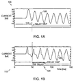
- Fig. 1 shows a comparison between timing of tripping of a relay of a protective device when a CT is saturated or unsaturated. Both graphs display a CT current measurement in kiloAmps versus time in milliseconds. In the top graph 100, the CT is not saturated, and the current measurement 105 accurately reflects the line current. A relay trips in response to the current measurement at a time t (110) approximately three quarters of a cycle after the excess current begins. In the bottom graph 115, the CT is saturated such that the measured current 120 does not accurately reflect the primary current (as indicated by measured current 105).
- the RMS value of the measured current does not reach a value sufficient to trip the relay until a time t d (125), which is delayed relative to t (110) by approximately two cycles. This delay may cause mis-coordination with other devices in the system. Furthermore, CT saturation may prevent relay tripping altogether, or may cause false tripping.
- CT saturation There are several ways to avoid CT saturation.
- the size of the CT core may be increased to change the mutual inductance between the coils.
- another core material which supports larger flux densities may be used.
- both options may increase the cost and complexity of protective device implementation.
- An ANN includes one or more nodes, or simple processors, which communicate with each other through channels.
- a node includes memory and implements a transfer function such that an output of the node is a function of one or more of its current or former inputs.
- a node receives input data, typically in the form of numerical data, through one or more input channels and operates on this input data using the transfer function.
- a node provides data to one or more channels within the ANN or to an output channel of the ANN.
- ANNs The transfer functions of the nodes of an ANN are established through a training process. ANNs are able to generalize beyond the data used in the training.
- the overall function of the ANN is dependent on the structure of the nodes and channels, the strengths of the channels, and the processing at each node. Additional information about ANNs may be found at the Neural Network FAQ, Sarle, W.S., ed. (1997), periodic posting to the Usenet newsgroup comp.ai.neural-nets, URL: ftp://ftp.sas.com/pub/neural/FAQ.html.
- the ANN is trained to provide the inverse of a transfer function of the CT.
- the ANN is then used to process the output (secondary current) from the CT to provide an estimate of the input (primary current) of the CT.
- One implementation of the ANN has been developed using MATLAB and trained using data generated from Electro Magnetic Transient Program (EMTP) simulations and from actual CTs.
- EMTP Electro Magnetic Transient Program
- Fig. 2 shows a current protection system 200 which uses ANNs to correct for CT saturation.
- the system 200 may be implemented in digital electronic circuitry, in computer hardware, in firmware, in software, or as a combination of these elements.
- Fig. 2 shows implementation of the system 200 as software running on a processor 205, such as a general purpose computer or a digital signal processor, having memory 210.
- processor 205 such as a general purpose computer or a digital signal processor, having memory 210.
- subsequent discussions often refer to implementation of the system 200 using digital electronic circuitry.
- the system 200 may be implemented effectively using software or other approaches.
- a line current 215 is measured by a CT 220 connected to receive the line current.
- An analog-to-digital converter 222 converts the current measurement from the CT 220 into a sequence of digital samples and supplies the digital sample to the computer 205.
- a switching algorithm 225 running on the computer 205 monitors an instantaneous current level and determines within which of three ranges the current level falls. Dividing the wide range of potential fault currents into three narrower ranges improves accuracy of the estimate of the CT input. In a first range, the current is expected to be low enough so that no CT saturation will occur. In second and third ranges, the current may be high enough to produce CT saturation.
- the switching algorithm 225 determines that the current level falls in the first range, the switching algorithm controls a multiplexer 227 to bypass the ANNs and send the current value directly to a protective device 230 such as a relay.
- the switching algorithm 225 determines that the current level falls in the second range, the switching algorithm controls the multiplexer 227 to provide the output of a first ANN 235 to the protective device 230.
- the switching algorithm controls the multiplexer 227 to send the output of a second ANN 240 to the protective device 230.
- the switching algorithm 225 may control whether the ANNs are even employed with respect to a current sample.
- the memory 210 also receives the current samples.
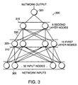
- Fig. 3 illustrates the structure 300 of ANNs 235 and 240.
- the ANN structure is a feed-forward type network with an input layer 305, a first hidden layer 310, a second hidden layer 315, and an output layer 320.
- a feed-forward topology is used because of its simplicity and inherent stability.
- a node 325 is represented by an open circle in the structure 300 and a channel 330 is represented by a line which connects one node to another node.
- the input layer 305 has 32 input nodes. The number of input nodes is chosen based on a typical signal sampling rate of 32 samples per 60 Hz cycle.
- the first hidden layer 310 has ten nodes, and the second hidden layer 315 has six nodes.
- the output layer 320 has a single node.
- Each node in the second hidden layer 315 sums weighted outputs of the nodes of the first hidden layer 310 and applies a non-linear tan-sigmoidal function to the sum.
- the node in the output layer 320 accumulates a weighted sum of outputs of the six hidden nodes in the second hidden layer 315 and processes the sum through a tan-sigmoidal function.
- a simplified ANN uses a network structure including a three-node hidden layer 405, a six-node input layer 410, and an output node 415.
- the number of input nodes, six may be based on a signal sampling rate of six samples per 60 Hz cycle. Since behavior of the CT in a cycle is dependent on a previous cycle, one input node 420 of the ANN receives a summation of the samples from the previous cycle. This summation is proportional to an integral of the secondary current and the flux during the previous cycle. Each new sample from the CT 220 is introduced to a "front" of the ANN at node 425.
- the previous sample is shifted down a node to the nearest node (shifting is represented by a curved arrow 430 connecting nodes in input layer).
- Samples from a last node 435 enter a six sample accumulator 440 which performs the summing and outputs the sum to node 420.
- the ANN runs for each new sample and thus produces a new output estimate for each sample.
- the ANN produces an estimate of the input of the CT based on a recent sample, previous four samples, and the summation of six previous samples preceding the previous four samples.
- the ANNs of Fig. 3 similarly operate on the current sample, the previous 30 samples, and the sum of the 32 samples preceding these 30 samples.
- Step 510 includes introducing each new sample to a first node 425 of the input layer 410, shifting the previous sample down a node in the input layer 315, providing the sample in the last node 435 to the accumulator 440 which sums the previous samples with the sample from node 435, and sending the result to node 420.
- a magnitude of the current sample is compared to a first threshold (step 515).
- the signal is applied to the protective device 230 (step 520), and the ANN is bypassed. Since most protective devices make operating decisions based on the RMS value of a current, the protective device may include a calculation of the RMS value of the last 32 samples.
- the current magnitude is compared to a second threshold (step 525). If the current magnitude is less than the second threshold, then ANN 235 is applied using an appropriate set of channel weight factors (step 530). The output of the ANN is an estimate of the true CT input current. This estimate is converted to a corresponding current measurement using an ideal transfer function for the CT (step 535). If the current magnitude is greater than or equal to the second threshold, then the ANN 240 is applied using an appropriate set of channel weight factors (step 540). The output of the ANN is an estimate of the true CT input current. This estimate is converted to a corresponding current measurement using the ideal transfer function for the CT (step 535). The converted output is applied to the protective device (step 545).
- the ANN is trained using MATLAB with data from EMTP simulations and data generated from actual CTs.
- the ANN is not trained for unsaturated faults, since these are handled by the protective device 230 without use of the ANN.
- only values representing the second and third ranges are used in training since the first range involves unsaturated CT signals and no correction is needed.
- the switching algorithm 225 described in Figs. 2 and 5 ensures that the ANN 235 or 240 is bypassed for unsaturated faults.
- Fig. 6 shows a flow chart of an ANN training procedure 600.
- a range of training cases are defined and the ANN is applied for each case.
- Variables for the test cases include fault magnitude, X/R ratio, and fault closing angle.
- the X/R ratio represents a level of DC offset.
- the fault closing angle represents the direction of the DC offset - either positive or negative with respect to the zero value of a symmetrical fault.
- the range of training cases is chosen to cover an expected operation of the CT.
- fault magnitudes of 5, 8, 10, 13, and 15 kA RMS symmetrical are input into the training procedure 600 (step 605).
- peak currents of almost two times those of symmetrical faults are possible.
- X/R ratios of 5, 10, and 20 may be input into the training procedure 600 (step 610).
- four unique test cases, with fault closing angles 90 degrees apart, are generated and input into the training procedure 600 (step 615).
- an EMTP training system 700 includes an EMTP 705 that receives variable sets 710 providing the test cases for the EMTP 705.
- the EMTP 705 simulates response of the CT by modelling CT behavior based on an equivalent circuit diagram shown in Fig. 8. Referring to Fig.
- a primary current 750 in an ideal CT 220 induces a secondary current 755 in the ideal CT 220 which is loaded with some impedance 760.
- Resistance 765 and leakage inductance 770 in the primary winding and resistance 775 and leakage inductance 780 in the secondary winding are represented in Fig. 8 as well.
- An exciting or magnetizing current 785 is dependent on a magnetizing impedance, which is represented by an iron loss equivalent resistance 790 in parallel with a magnetizing non-linear inductance 795.
- Data from the EMTP must be converted to a form usable by a MATLAB training algorithm 715 (step 625). Training is conducted until an error 720 between modelled CT currents and ANN-estimated currents reaches an acceptable level (step 630).
- fault cases are generated using actual CT primary and secondary currents recorded in digital form (step 635).
- the data is converted to a format usable by MATLAB (step 640) and then the ANN is trained (step 645) using the actual CT data.
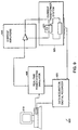
- Fig. 9 shows a CT testing system 800 which uses data generated from an actual CT 220.
- a real-time power system simulator (RTPSS) 805 is used to accurately simulate real power system operation.
- the RTPSS 805 is controlled using a computer 810.
- it is an analog-based device which employs high fidelity voltage and current amplifiers 815 which simulate high fault currents which may contain DC offset.
- CT primary and secondary currents are recorded using a digital recorder 820.
- a test system 825 similar to the protection system 200 of Fig. 2, is used to determine within which range a current level falls.
- the ANN is bypassed and if the fault current is above the first threshold, the ANN (with appropriate weight factors) is implemented to estimate the CT current.
- ANN output is compared to the input generated by the RTPSS 805 and trials continue until the difference is below an acceptable level.
- the protection system 200 may be tested using actual CT data generated from the RTPSS 805 of Fig. 9. Several test cases, with various offsets and fault magnitudes, are performed using MATLAB.
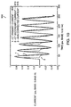
- Fig. 10 shows a graph 900 of primary CT current 905, secondary CT current 910, and ANN output 915 of a first test case in which a high fault current with positive-going DC offset causes significant CT saturation and results in secondary current distortion.
- the fault current exceeds the second threshold, and, therefore, is processed by ANN 240.
- the CT error correction by ANN 240 is in agreement with primary CT current 905.
- Fig. 11 shows a graph 920 of RMS values of the same waveforms of Fig. 10.
- RMS values of the primary CT current 925 are in good agreement with RMS values of the ANN corrected current 930.
- RMS values of the secondary CT current 935 display the effects of CT saturation shown in Fig. 10. The RMS value increases to an asymptotic value 940 of the fault after one cycle.
- Fig. 12 shows a graph 1000 of primary CT current 1005, secondary CT current 1010, and ANN output 1015 of a second test case in which a fault current with negative-going DC offset caused CT saturation and resulted in secondary current distortion.
- the fault current exceeded the first threshold but not the second threshold, thus it was processed by ANN 235.
- the CT error correction by ANN 235 is in agreement with primary CT current 1005.
- Fig. 13 shows a graph 1020 of RMS values of the same waveforms of Fig. 12.
- RMS values of the primary CT current 1025 are in good agreement with RMS values of the ANN corrected current 1030.
- RMS values of the secondary CT current 1035 display the effects of CT saturation shown in Fig. 12.
- the RMS value increases to an asymptotic value 1040 of the fault after one cycle.
- the algorithm 225 was implemented on a digital signal processor (DSP).
- the algorithm 225 was coded in DSP assembly language and was then run on a DSP simulator.
- the DSP simulator accurately simulated the performance of a real DSP processor.
- Testing of the algorithm was done using a PC-based DSP simulator for the processor which reads saved data files from actual CTs and writes output files which are analyzed for error.
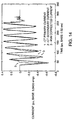
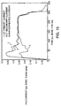
- Figs. 14 and 15 show the same test case as Figs. 12 and 13 processed on the DSP simulator using a fixed-point arithmetic in the algorithm. Results from the DSP simulator (Figs. 14 and 15) are in good agreement with results from MATLAB (Figs. 12 and 13).
- results from the DSP simulation indicate that the total algorithm 225 may be executed within 130 ⁇ s per sample per phase of signal and may require less than 1.1 K of memory.
Landscapes
- Engineering & Computer Science (AREA)
- Power Engineering (AREA)
- Artificial Intelligence (AREA)
- Evolutionary Computation (AREA)
- Measurement Of Current Or Voltage (AREA)
- Emergency Protection Circuit Devices (AREA)
- Protection Of Transformers (AREA)
Abstract
Description
- This invention relates to correcting for current transformer signal distortions.
- Iron-core toroidal current transformers (CTs) are widely used in the electric power industry to measure line current for protection and metering purposes. The line current is applied to a primary coil of the CT, and a reduced-magnitude version of the line current is produced on a secondary coil of the CT. This reduced-magnitude version of the line current is used as a measurement for protection and metering purposes.
- One advantage of using an iron core CT is that most of the magnetic flux produced by a current in the primary winding passes through the secondary winding. Thus, iron-core CTs provide good flux linkage between the primary and secondary windings. Other advantages of using an iron-core toroidal CT include low production cost, inherent galvanic isolation, reliability, and ease of application.
- However, a major disadvantage of iron-core toroidal CTs is that they are prone to current saturation. Such saturation occurs when currents exceeding a dynamic operating range of the CT cause magnetization of the core to be independent of the current, and thus produce distortion in the secondary signal. Saturation in these CTs is due mainly to two factors. First, the relationship between a magnetizing current (i.e., a current which produces the flux required to induce a voltage for transformer action) and a voltage applied to the secondary winding is non-linear. Second, iron-core toroidal CTs are able to retain a large magnetic flux density, or remanence, in their cores after removal of a current applied to the primary winding.
- The invention provides techniques for correcting for saturation in a current transformer used to provide a current measurement. To this end, a current measurement received from a current transformer is provided to an artificial neural network. The artificial neural network is trained to implement an inverse transfer function of the current transformer and produces an output that accounts for saturation of the current transformer.
- Embodiments may include one or more of the following features. For example, the output of the artificial neural network may be converted to a projected current measurement using an ideal transfer function for the current transformer. The projected current measurement is provided to a protective device which signals a relay to trip if the projected current measurement is greater than a predetermined value.
- The current measurement may be provided to one of two artificial neural networks, with the particular artificial neural network used depending on whether the current measurement is greater than a predetermined threshold. Both artificial neural networks are trained to implement inverse transfer functions of the current transformer, but under different operating conditions (e.g., different current levels)
- The artificial neural network may be bypassed if the current measurement is less than a first threshold. When the artificial neural network is bypassed, the current measurement may be provided directly to a protective device which signals a relay to trip if the current measurement is greater than a predetermined value.
- The artificial neural network may be trained using data from Electro Magnetic Transient Program simulations. The artificial neural network also may be trained using data from actual current transformers.
- The current measurement from the current transformer may be converted into a sequence of digital samples. An input of the artificial neural network may be a digital sample from a current cycle. Another input of the artificial neural network may be based on digital samples from a previous current cycle.
- The current measurement may be monitored to determine within which of several ranges the measurement falls. If the measurement falls in a first range, the artificial neural network may be bypassed and the current measurement may be provided directly to a protective device. If the measurement falls in a second range, the current measurement may be provided to a first artificial neural network. If the measurement falls in a third range, the current measurement may be provided to another artificial neural network.
- Other features and advantages will be apparent from the following description, including the drawings, and from the claims.
-
- Fig. 1 includes two graphs illustrating effects of current saturation in a current transformer (CT) on tripping of a relay.
- Fig. 2 is a block diagram of a protection system used to address CT saturation.
- Fig. 3 is a block diagram of an artificial neural network (ANN) used for CT saturation compensation.
- Fig. 4 is a simplified block diagram showing operation of an ANN.
- Fig. 5 is a flow chart of a procedure for using ANNs to compensate for CT saturation.
- Fig. 6 is a flow chart of an ANN training procedure.
- Fig. 7 is a block diagram of an Electro Magnetic Transient Program (EMTP) simulation system used in the training system.
- Fig. 8 is a circuit diagram of a CT model used in the EMTP of Fig. 7.
- Fig. 9 is a block diagram of a CT testing system which uses data from a real-time power system simulator (RTPSS).
- Fig. 10 is a graph of a first test case of the protection system.
- Fig. 11 is a graph of root-mean square (RMS) values of the waveforms of Fig. 10.
- Fig. 12 is a graph of a second test case of the protection system.
- Fig. 13 is a graph of root-mean square (RMS) values of the waveforms of Fig. 12.
- Figs. 14 and 15 are graphs of a digital signal processor (DSP) simulation using the second test case of Figs. 12 and 13.
-
- In many electric power designs, a current transformer (CT) is an integral part of a protective device that detects and responds to current faults on a power line. If a fault includes a significant DC offset superimposed on a symmetrical current, the CT may saturate at an unusually low current. Both electromechanical and electrical protective devices often make operating decisions based on a root mean square (RMS) value of a fault current. If the signal supplied by the CT to the protective device is distorted by saturation, the RMS value sensed may be different than the actual fault current.
- Fig. 1 shows a comparison between timing of tripping of a relay of a protective device when a CT is saturated or unsaturated. Both graphs display a CT current measurement in kiloAmps versus time in milliseconds. In the
top graph 100, the CT is not saturated, and thecurrent measurement 105 accurately reflects the line current. A relay trips in response to the current measurement at a time t (110) approximately three quarters of a cycle after the excess current begins. In thebottom graph 115, the CT is saturated such that the measuredcurrent 120 does not accurately reflect the primary current (as indicated by measured current 105). As a result of this saturation, the RMS value of the measured current does not reach a value sufficient to trip the relay until a time td (125), which is delayed relative to t (110) by approximately two cycles. This delay may cause mis-coordination with other devices in the system. Furthermore, CT saturation may prevent relay tripping altogether, or may cause false tripping. - There are several ways to avoid CT saturation. For example, the size of the CT core may be increased to change the mutual inductance between the coils. Alternately, another core material which supports larger flux densities may be used. However, both options may increase the cost and complexity of protective device implementation.
- Another way to address CT saturation is to correct for the CT saturation using an artificial neural network (ANN). An ANN includes one or more nodes, or simple processors, which communicate with each other through channels. Typically, a node includes memory and implements a transfer function such that an output of the node is a function of one or more of its current or former inputs. A node receives input data, typically in the form of numerical data, through one or more input channels and operates on this input data using the transfer function. A node provides data to one or more channels within the ANN or to an output channel of the ANN.
- The transfer functions of the nodes of an ANN are established through a training process. ANNs are able to generalize beyond the data used in the training.
- The overall function of the ANN is dependent on the structure of the nodes and channels, the strengths of the channels, and the processing at each node. Additional information about ANNs may be found at the Neural Network FAQ, Sarle, W.S., ed. (1997), periodic posting to the Usenet newsgroup comp.ai.neural-nets, URL: ftp://ftp.sas.com/pub/neural/FAQ.html.
- The ANN is trained to provide the inverse of a transfer function of the CT. The ANN is then used to process the output (secondary current) from the CT to provide an estimate of the input (primary current) of the CT. One implementation of the ANN has been developed using MATLAB and trained using data generated from Electro Magnetic Transient Program (EMTP) simulations and from actual CTs.
- Fig. 2 shows a
current protection system 200 which uses ANNs to correct for CT saturation. Thesystem 200 may be implemented in digital electronic circuitry, in computer hardware, in firmware, in software, or as a combination of these elements. For example, Fig. 2 shows implementation of thesystem 200 as software running on aprocessor 205, such as a general purpose computer or a digital signal processor, havingmemory 210. For ease of description, subsequent discussions often refer to implementation of thesystem 200 using digital electronic circuitry. However, it should be understood that thesystem 200 may be implemented effectively using software or other approaches. - Referring again to Fig. 2, a line current 215 is measured by a
CT 220 connected to receive the line current. An analog-to-digital converter 222 converts the current measurement from theCT 220 into a sequence of digital samples and supplies the digital sample to thecomputer 205. - A
switching algorithm 225 running on thecomputer 205 monitors an instantaneous current level and determines within which of three ranges the current level falls. Dividing the wide range of potential fault currents into three narrower ranges improves accuracy of the estimate of the CT input. In a first range, the current is expected to be low enough so that no CT saturation will occur. In second and third ranges, the current may be high enough to produce CT saturation. When theswitching algorithm 225 determines that the current level falls in the first range, the switching algorithm controls amultiplexer 227 to bypass the ANNs and send the current value directly to aprotective device 230 such as a relay. When theswitching algorithm 225 determines that the current level falls in the second range, the switching algorithm controls themultiplexer 227 to provide the output of afirst ANN 235 to theprotective device 230. When theswitching algorithm 225 determines that the current level falls in the third range, the switching algorithm controls themultiplexer 227 to send the output of asecond ANN 240 to theprotective device 230. In other implementations, theswitching algorithm 225 may control whether the ANNs are even employed with respect to a current sample. Thememory 210 also receives the current samples. - Fig. 3 illustrates the
structure 300 ofANNs input layer 305, a firsthidden layer 310, a secondhidden layer 315, and anoutput layer 320. A feed-forward topology is used because of its simplicity and inherent stability. Anode 325 is represented by an open circle in thestructure 300 and achannel 330 is represented by a line which connects one node to another node. Theinput layer 305 has 32 input nodes. The number of input nodes is chosen based on a typical signal sampling rate of 32 samples per 60 Hz cycle. The firsthidden layer 310 has ten nodes, and the secondhidden layer 315 has six nodes. Theoutput layer 320 has a single node. - Each of the nodes in the first
hidden layer 310 accumulates a sum of samples presented at theinput layer 305 multiplied by weighting factors for each channel. Once the sum is accumulated, it is operated on by the associated transfer function of the node, which is a non-linear - Each node in the second
hidden layer 315 sums weighted outputs of the nodes of the firsthidden layer 310 and applies a non-linearoutput layer 320 accumulates a weighted sum of outputs of the six hidden nodes in the secondhidden layer 315 and processes the sum through a - Referring to Fig. 4, a simplified ANN uses a network structure including a three-node hidden
layer 405, a six-node input layer 410, and anoutput node 415. For ease of description, in this simplified structure, the number of input nodes, six, may be based on a signal sampling rate of six samples per 60 Hz cycle. Since behavior of the CT in a cycle is dependent on a previous cycle, oneinput node 420 of the ANN receives a summation of the samples from the previous cycle. This summation is proportional to an integral of the secondary current and the flux during the previous cycle. Each new sample from theCT 220 is introduced to a "front" of the ANN atnode 425. The previous sample is shifted down a node to the nearest node (shifting is represented by acurved arrow 430 connecting nodes in input layer). Samples from alast node 435 enter a sixsample accumulator 440 which performs the summing and outputs the sum tonode 420. The ANN runs for each new sample and thus produces a new output estimate for each sample. Thus, the ANN produces an estimate of the input of the CT based on a recent sample, previous four samples, and the summation of six previous samples preceding the previous four samples. The ANNs of Fig. 3 similarly operate on the current sample, the previous 30 samples, and the sum of the 32 samples preceding these 30 samples. - Referring to Fig. 5, the
system 200 of Fig. 2 implements aprocedure 500 for compensation of CT saturation. A sampled CT current is input from a power source (step 505). Samples are input to a sample set and theaccumulator 440 is updated (step 510). Step 510 includes introducing each new sample to afirst node 425 of theinput layer 410, shifting the previous sample down a node in theinput layer 315, providing the sample in thelast node 435 to theaccumulator 440 which sums the previous samples with the sample fromnode 435, and sending the result tonode 420. A magnitude of the current sample is compared to a first threshold (step 515). If the current magnitude is less than the first threshold, then the signal is applied to the protective device 230 (step 520), and the ANN is bypassed. Since most protective devices make operating decisions based on the RMS value of a current, the protective device may include a calculation of the RMS value of the last 32 samples. - Next, the current magnitude is compared to a second threshold (step 525). If the current magnitude is less than the second threshold, then
ANN 235 is applied using an appropriate set of channel weight factors (step 530). The output of the ANN is an estimate of the true CT input current. This estimate is converted to a corresponding current measurement using an ideal transfer function for the CT (step 535). If the current magnitude is greater than or equal to the second threshold, then theANN 240 is applied using an appropriate set of channel weight factors (step 540). The output of the ANN is an estimate of the true CT input current. This estimate is converted to a corresponding current measurement using the ideal transfer function for the CT (step 535). The converted output is applied to the protective device (step 545). - The ANN is trained using MATLAB with data from EMTP simulations and data generated from actual CTs. The ANN is not trained for unsaturated faults, since these are handled by the
protective device 230 without use of the ANN. Thus, only values representing the second and third ranges are used in training since the first range involves unsaturated CT signals and no correction is needed. Theswitching algorithm 225 described in Figs. 2 and 5 ensures that theANN - Fig. 6 shows a flow chart of an
ANN training procedure 600. A range of training cases are defined and the ANN is applied for each case. Variables for the test cases include fault magnitude, X/R ratio, and fault closing angle. The X/R ratio represents a level of DC offset. The fault closing angle represents the direction of the DC offset - either positive or negative with respect to the zero value of a symmetrical fault. The range of training cases is chosen to cover an expected operation of the CT. For a 1000:1 A CT, for example, fault magnitudes of 5, 8, 10, 13, and 15 kA RMS symmetrical are input into the training procedure 600 (step 605). For high X/R ratios, peak currents of almost two times those of symmetrical faults are possible. For the purposes of training, X/R ratios of 5, 10, and 20 may be input into the training procedure 600 (step 610). In one implementation, four unique test cases, with fault closing angles 90 degrees apart, are generated and input into the training procedure 600 (step 615). - ANN training is accomplished when the ANN provides the inverse of the CT transfer function. When this occurs, the ANN is trained and may be used to estimate the input of the CT. Combining all three variable sets, there may be about 40 cases to train the ANN. After the test cases are defined by entering the fault magnitudes, X/R ratios, and fault closing angles, test data is generated using an Electro Magnetic Transient Program (EMTP) (step 620). Referring also to Fig. 7, an
EMTP training system 700 includes anEMTP 705 that receivesvariable sets 710 providing the test cases for theEMTP 705. TheEMTP 705 simulates response of the CT by modelling CT behavior based on an equivalent circuit diagram shown in Fig. 8. Referring to Fig. 8, a primary current 750 in anideal CT 220 induces a secondary current 755 in theideal CT 220 which is loaded with someimpedance 760.Resistance 765 and leakage inductance 770 in the primary winding andresistance 775 and leakage inductance 780 in the secondary winding are represented in Fig. 8 as well. An exciting or magnetizing current 785 is dependent on a magnetizing impedance, which is represented by an iron lossequivalent resistance 790 in parallel with a magnetizingnon-linear inductance 795. - Data from the EMTP must be converted to a form usable by a MATLAB training algorithm 715 (step 625). Training is conducted until an
error 720 between modelled CT currents and ANN-estimated currents reaches an acceptable level (step 630). - After the basic operation of the ANN is confirmed using EMTP, fault cases are generated using actual CT primary and secondary currents recorded in digital form (step 635). The data is converted to a format usable by MATLAB (step 640) and then the ANN is trained (step 645) using the actual CT data.
- Fig. 9 shows a CT testing system 800 which uses data generated from an
actual CT 220. To obtain test data, a real-time power system simulator (RTPSS) 805 is used to accurately simulate real power system operation. TheRTPSS 805 is controlled using acomputer 810. Furthermore, it is an analog-based device which employs high fidelity voltage andcurrent amplifiers 815 which simulate high fault currents which may contain DC offset. With appropriate data acquisition techniques, CT primary and secondary currents are recorded using adigital recorder 820. Atest system 825, similar to theprotection system 200 of Fig. 2, is used to determine within which range a current level falls. Thus, if the fault current is below a first threshold, the ANN is bypassed and if the fault current is above the first threshold, the ANN (with appropriate weight factors) is implemented to estimate the CT current. ANN output is compared to the input generated by theRTPSS 805 and trials continue until the difference is below an acceptable level. - Once training is finished, the
protection system 200 may be tested using actual CT data generated from theRTPSS 805 of Fig. 9. Several test cases, with various offsets and fault magnitudes, are performed using MATLAB. - Fig. 10 shows a
graph 900 of primary CT current 905, secondary CT current 910, andANN output 915 of a first test case in which a high fault current with positive-going DC offset causes significant CT saturation and results in secondary current distortion. The fault current exceeds the second threshold, and, therefore, is processed byANN 240. As evidenced ingraph 900, the CT error correction byANN 240 is in agreement with primary CT current 905. - Fig. 11 shows a
graph 920 of RMS values of the same waveforms of Fig. 10. RMS values are calculated by theprotective device 230 using the following equation:asymptotic value 940 of the fault after one cycle. - Fig. 12 shows a
graph 1000 of primary CT current 1005, secondary CT current 1010, andANN output 1015 of a second test case in which a fault current with negative-going DC offset caused CT saturation and resulted in secondary current distortion. The fault current exceeded the first threshold but not the second threshold, thus it was processed byANN 235. As evidenced ingraph 1000, the CT error correction byANN 235 is in agreement with primary CT current 1005. - Fig. 13 shows a graph 1020 of RMS values of the same waveforms of Fig. 12. RMS values of the primary CT current 1025 are in good agreement with RMS values of the ANN corrected current 1030. RMS values of the secondary CT current 1035 display the effects of CT saturation shown in Fig. 12. The RMS value increases to an
asymptotic value 1040 of the fault after one cycle. - Results of all test cases, including those in Figs. 10-13, show that the
protection system 200 successfully estimates the true primary CT current from a saturated secondary CT output under realistic fault conditions. - To verify that the
protection system 200 may be applied in real-time, thealgorithm 225 was implemented on a digital signal processor (DSP). Thealgorithm 225 was coded in DSP assembly language and was then run on a DSP simulator. The DSP simulator accurately simulated the performance of a real DSP processor. Testing of the algorithm was done using a PC-based DSP simulator for the processor which reads saved data files from actual CTs and writes output files which are analyzed for error. Figs. 14 and 15 show the same test case as Figs. 12 and 13 processed on the DSP simulator using a fixed-point arithmetic in the algorithm. Results from the DSP simulator (Figs. 14 and 15) are in good agreement with results from MATLAB (Figs. 12 and 13). Furthermore, results from the DSP simulation indicate that thetotal algorithm 225 may be executed within 130 µs per sample per phase of signal and may require less than 1.1 K of memory.
Claims (27)
- A method of correcting for saturation in a current transformer used to provide a current measurement, the method comprising:receiving a current measurement from the current transformer; andproviding the current measurement to an artificial neural network, the artificial neural network being trained to implement an inverse transfer function of the current transformer and producing an output that accounts for saturation of the current transformer.
- The method of claim 1, further comprising converting the output of the artificial neural network to a projected current measurement using an ideal transfer function for the current transformer.
- The method of claim 2, further comprising providing the projected current measurement to a protective device.
- The method of claim 3, wherein the protective device signals a relay to trip if the projected current measurement is greater than a predetermined value.
- The method of claim 1, further comprising providing the current measurement to another artificial neural network if the current measurement is greater than a predetermined threshold, the other artificial neural network being trained to implement an inverse transfer function of the current transformer and producing an output that accounts for saturation of the current transformer.
- The method of claim 5, further comprising converting the output of the other artificial neural network to a projected current measurement using an ideal transfer function for the current transformer.
- The method of claim 6, further comprising providing the projected current measurement to a protective device, wherein the protective device signals a relay to trip if the projected current measurement is greater than a predetermined value.
- The method of claim 1, further comprising bypassing the artificial neural network if the current measurement is less than a first threshold.
- The method of claim 8, further comprising providing the current measurement to a protective device when the artificial neural network is bypassed.
- The method of claim 9, wherein the protective device signals a relay to trip if the current measurement is greater than a predetermined value.
- The method of claim 1, wherein receiving the current measurement includes converting the current measurement into a sequence of digital samples.
- The method of claim 1, further comprising training the artificial neural network using data from Electro Magnetic Transient Program simulations.
- The method of claim 1, further comprising training the artificial neural network using data from actual current transformers.
- The method of claim 1, wherein a first input of the artificial neural network comprises the current measurement, and a second input of the artificial neural network comprises a previous current measurement.
- The method of claim 14, wherein a third input of the artificial neural network comprises a combination of previous current measurements.
- The method of claim 1, further comprising:monitoring the current measurement; anddetermining within which of a plurality of ranges the current measurement falls.
- The method of claim 16, further comprising:if the current measurement falls in a first range, bypassing the artificial neural network and providing the current measurement directly to a protective device;if the current measurement falls in a second range, providing the current measurement to a first artificial neural network; andif the current measurement falls in a third range, providing the current measurement to a second artificial neural network.
- A current transformer saturation correction apparatus used in a power system, the apparatus comprising:a current transformer; andan artificial neural network connected to receive an output of the current transformer and trained to implement an inverse transfer function of the current transformer, the artificial neural network providing an output that accounts for saturation of the current transformer.
- The apparatus of claim 18, further comprising a protective device connected to receive the output of the artificial neural network.
- The apparatus of claim 18, further comprising a second artificial neural network connected to receive an output of the current transformer and trained to implement an inverse transfer function of the current transformer, the second artificial neural network providing an output that accounts for saturation of the current transformer.
- The apparatus of claim 20, further comprising a switching system which monitors the current measurement and determines within which of a plurality of ranges the current measurement falls.
- The apparatus of claim 21, wherein when the current measurement falls in a first range, the output of the current transformer is provided directly to a protective device and the artificial neural networks are bypassed.
- The apparatus of claim 21, wherein when the current measurement falls in a second range, the output of the current transformer is provided to the first artificial neural network.
- The apparatus of claim 23, further comprising a converter that converts an output of the artificial neural network to a projected current measurement using an ideal transfer function for the current transformer.
- The apparatus of claim 24, further comprising a protective device connected to receive the projected current measurement.
- The apparatus of claim 21, wherein when the value falls in a third range, the output of the current transformer is provided to the second artificial neural network.
- The apparatus of claim 18, further comprising an analog-to-digital converter which converts the current measurement into a sequence of digital samples.
Applications Claiming Priority (5)
| Application Number | Priority Date | Filing Date | Title |
|---|---|---|---|
| US9645998P | 1998-08-13 | 1998-08-13 | |
| US96459P | 1998-08-13 | ||
| US96459 | 1998-08-13 | ||
| US09/275,388 US6247003B1 (en) | 1998-08-13 | 1999-03-24 | Current transformer saturation correction using artificial neural networks |
| US275388 | 1999-03-24 |
Publications (2)
| Publication Number | Publication Date |
|---|---|
| EP0980129A2 true EP0980129A2 (en) | 2000-02-16 |
| EP0980129A3 EP0980129A3 (en) | 2001-01-17 |
Family
ID=26791731
Family Applications (1)
| Application Number | Title | Priority Date | Filing Date |
|---|---|---|---|
| EP99306284A Withdrawn EP0980129A3 (en) | 1998-08-13 | 1999-08-09 | Current transformer saturation correction using artificial neural networks |
Country Status (8)
| Country | Link |
|---|---|
| US (1) | US6247003B1 (en) |
| EP (1) | EP0980129A3 (en) |
| KR (1) | KR20000017181A (en) |
| CN (1) | CN1246620A (en) |
| AU (1) | AU750864B2 (en) |
| BR (1) | BR9903589A (en) |
| CA (1) | CA2280281C (en) |
| TW (1) | TW496026B (en) |
Cited By (3)
| Publication number | Priority date | Publication date | Assignee | Title |
|---|---|---|---|---|
| EP1287599B1 (en) * | 2000-06-09 | 2011-11-02 | Siemens Aktiengesellschaft | Software-controlled evaluation of fault current for protection and monitoring systems |
| US8395373B2 (en) | 2008-03-28 | 2013-03-12 | Abb Technology Ag | Phasor estimation during current transformer saturation |
| WO2017001950A1 (en) | 2015-06-29 | 2017-01-05 | Abb Technology Ltd. | A method for correcting effect of saturation in current transformer and an intelligent electronic device therefor |
Families Citing this family (18)
| Publication number | Priority date | Publication date | Assignee | Title |
|---|---|---|---|---|
| US6617839B2 (en) * | 2000-07-12 | 2003-09-09 | Yong-Cheol Kang | Method for detecting current transformer saturation |
| MY150874A (en) * | 2006-10-13 | 2014-03-14 | Tnb Res Sdn Bhd | Flashover analysis tool |
| CN102087311B (en) * | 2010-12-21 | 2013-03-06 | 彭浩明 | Method for improving measurement accuracy of power mutual inductor |
| US8576521B2 (en) | 2011-08-16 | 2013-11-05 | Schneider Electric USA, Inc. | Adaptive light detection for arc mitigation systems |
| US9053881B2 (en) | 2012-08-24 | 2015-06-09 | Schneider Electric USA, Inc. | Arc detection with resistance to nuisance activation through light subtraction |
| CN103761568A (en) * | 2014-01-23 | 2014-04-30 | 国家电网公司 | Daily load characteristic curve extracting method based on SOM neutral network clustering algorithm |
| US11636668B2 (en) | 2017-11-10 | 2023-04-25 | Nvidia Corp. | Bilateral convolution layer network for processing point clouds |
| CN112154340B (en) * | 2018-05-30 | 2024-03-19 | 三菱电机株式会社 | Characteristic testing system for protective relay devices |
| CN109375131B (en) * | 2018-07-31 | 2022-03-04 | 中国电力科学研究院有限公司 | A method and system for identifying saturation velocity and saturation depth of a current transformer |
| US10958062B2 (en) | 2018-11-13 | 2021-03-23 | Rockwell Automation Technologies, Inc. | Systems and methods for dynamically switching a load of a current transformer circuit |
| CN110045317B (en) * | 2019-05-29 | 2022-10-04 | 中国电力科学研究院有限公司 | Mutual inductor metering error online detection method and system |
| US12057111B2 (en) * | 2021-05-20 | 2024-08-06 | Nice Ltd. | System and method for voice biometrics authentication |
| US20250079003A1 (en) * | 2022-01-05 | 2025-03-06 | Ohio State Innovation Foundation | Automated systems for diagnosis and monitoring of stroke and related methods |
| CN115469259B (en) * | 2022-09-28 | 2024-05-24 | 武汉格蓝若智能技术股份有限公司 | CT error state online quantitative evaluation method and device based on RBF neural network |
| US12212272B2 (en) | 2023-01-10 | 2025-01-28 | Caterpillar Inc. | Genset control system using a modified root-mean-square current measurement |
| CN116430295A (en) * | 2023-04-19 | 2023-07-14 | 青岛鼎信通讯科技有限公司 | A Neural Network-Based Measuring and Correcting Method of Effective Value of Current Transformer |
| CN119905958B (en) * | 2024-12-16 | 2026-03-24 | 国网江苏省电力有限公司超高压分公司 | A method and system for converter transformer saturation protection based on fused networks |
| CN120295118B (en) * | 2025-03-28 | 2025-09-26 | 宜兴市中瑞电子科技有限公司 | Automatic intelligent compensation method and system for current transformer |
Family Cites Families (16)
| Publication number | Priority date | Publication date | Assignee | Title |
|---|---|---|---|---|
| US4946393A (en) | 1989-08-04 | 1990-08-07 | Amerace Corporation | Separable connector access port and fittings |
| US5082449A (en) | 1990-08-28 | 1992-01-21 | Amerace Corporation | Removable media injection fitting |
| US5485545A (en) | 1991-06-20 | 1996-01-16 | Mitsubishi Denki Kabushiki Kaisha | Control method using neural networks and a voltage/reactive-power controller for a power system using the control method |
| US5258903A (en) | 1991-12-16 | 1993-11-02 | Thomson Consumer Electronics | Control circuit and power supply for televisions |
| JPH06201751A (en) * | 1993-01-06 | 1994-07-22 | Hitachi Cable Ltd | Power transmission line failure segment locating device |
| DE4333260C2 (en) | 1993-09-27 | 1997-09-11 | Siemens Ag | Method for generating an excitation signal |
| US5537327A (en) | 1993-10-22 | 1996-07-16 | New York State Electric & Gas Corporation | Method and apparatus for detecting high-impedance faults in electrical power systems |
| FR2714771B1 (en) * | 1994-01-06 | 1996-02-02 | Merlin Gerin | Differential protection device for a power transformer. |
| US5629870A (en) | 1994-05-31 | 1997-05-13 | Siemens Energy & Automation, Inc. | Method and apparatus for predicting electric induction machine failure during operation |
| US5574387A (en) | 1994-06-30 | 1996-11-12 | Siemens Corporate Research, Inc. | Radial basis function neural network autoassociator and method for induction motor monitoring |
| US5576632A (en) | 1994-06-30 | 1996-11-19 | Siemens Corporate Research, Inc. | Neural network auto-associator and method for induction motor monitoring |
| US5450315A (en) * | 1994-09-26 | 1995-09-12 | Square D Company | Apparatus using a neural network for power factor calculation |
| KR0180628B1 (en) * | 1996-05-14 | 1999-05-15 | 이종훈 | Error recovery device and method of transformer using neural network |
| KR100199554B1 (en) | 1996-05-18 | 1999-06-15 | 김일동 | Variable autonomous time automatic reclosing apparatus in transmission line protection relay system and method thereof |
| US5714886A (en) | 1996-12-26 | 1998-02-03 | Square D Company | Method of calibrating the trip point of an overload relay |
| US5796631A (en) | 1997-02-10 | 1998-08-18 | Tempo Instrument, Inc. | Method and apparatus for monitoring and characterizing power quality, faults and other phenomena in network power systems |
-
1999
- 1999-03-24 US US09/275,388 patent/US6247003B1/en not_active Expired - Fee Related
- 1999-08-09 EP EP99306284A patent/EP0980129A3/en not_active Withdrawn
- 1999-08-09 KR KR1019990032494A patent/KR20000017181A/en not_active Abandoned
- 1999-08-12 AU AU44445/99A patent/AU750864B2/en not_active Ceased
- 1999-08-12 CA CA002280281A patent/CA2280281C/en not_active Expired - Fee Related
- 1999-08-13 CN CN99117795A patent/CN1246620A/en active Pending
- 1999-08-13 BR BR9903589-8A patent/BR9903589A/en not_active IP Right Cessation
- 1999-08-20 TW TW088113812A patent/TW496026B/en not_active IP Right Cessation
Non-Patent Citations (1)
| Title |
|---|
| COZZIO R ET AL.: "Neural signal processing networks for electric power distribution system control", BULLETIN DES SCHWEIZERISCHEN ELEKTROTECHNISCHEN VEREINS & DES VERBANDES SCHWEIZERISCHER ELECKTRIZITAETSWERKE, vol. 85, no. 7, 31 March 1994 (1994-03-31), pages 23 - 29 |
Cited By (4)
| Publication number | Priority date | Publication date | Assignee | Title |
|---|---|---|---|---|
| EP1287599B1 (en) * | 2000-06-09 | 2011-11-02 | Siemens Aktiengesellschaft | Software-controlled evaluation of fault current for protection and monitoring systems |
| US8395373B2 (en) | 2008-03-28 | 2013-03-12 | Abb Technology Ag | Phasor estimation during current transformer saturation |
| WO2017001950A1 (en) | 2015-06-29 | 2017-01-05 | Abb Technology Ltd. | A method for correcting effect of saturation in current transformer and an intelligent electronic device therefor |
| US10263507B2 (en) | 2015-06-29 | 2019-04-16 | Abb Schweiz Ag | Method for correcting effect of saturation in current transformer and an intelligent electronic device therefor |
Also Published As
| Publication number | Publication date |
|---|---|
| AU4444599A (en) | 2000-03-09 |
| US6247003B1 (en) | 2001-06-12 |
| CA2280281C (en) | 2002-09-03 |
| EP0980129A3 (en) | 2001-01-17 |
| BR9903589A (en) | 2000-08-29 |
| CA2280281A1 (en) | 2000-02-13 |
| CN1246620A (en) | 2000-03-08 |
| AU750864B2 (en) | 2002-08-01 |
| TW496026B (en) | 2002-07-21 |
| KR20000017181A (en) | 2000-03-25 |
Similar Documents
| Publication | Publication Date | Title |
|---|---|---|
| US6247003B1 (en) | Current transformer saturation correction using artificial neural networks | |
| Yu et al. | Correction of current transformer distorted secondary currents due to saturation using artificial neural networks | |
| Khorashadi-Zadeh et al. | Correction of saturated current transformers secondary current using ANNs | |
| Hargrave et al. | Beyond the knee point: A practical guide to CT saturation | |
| Kang et al. | A CT saturation detection algorithm | |
| Kang et al. | An algorithm for compensating secondary currents of current transformers | |
| Yu et al. | Neural network for current transformer saturation correction | |
| Haghjoo et al. | Compensation of CT distorted secondary current waveform in online conditions | |
| Kojovic | Impact of current transformer saturation on overcurrent protection operation | |
| McLaren et al. | A new directional element for numerical distance relays | |
| Saha et al. | Application of ANN methods for instrument transformer correction in transmission line protection | |
| Wath et al. | Error compensation method for current transformer | |
| El-Naggar et al. | A discrete dynamic filter for detecting and compensating CT saturation | |
| US6611136B2 (en) | Device for determining the primary current of a current transformer comprising saturation correction means | |
| Cummins et al. | Simplified artificial neural network structure with the current transformer saturation detector provides a good estimate of primary currents | |
| Russell et al. | Implementation and analysis of a digital model of the incremental-quantity distance element using emtp | |
| JP3167620B2 (en) | Harmonic outflow evaluation device | |
| Kojovic | Comparison of different current transformer modeling techniques for protection system studies | |
| Pereira et al. | Real time compensation algorithm for air-gapped current transformers saturation effects | |
| Zadeh et al. | A compensation scheme for CVT transient effects using artificial neural network | |
| JPH0884431A (en) | Method and apparatus for correcting current signal | |
| Zadeh et al. | Development and hardware implementation of a reliable protective relay data acquisition system | |
| Terzija et al. | Detection of arcing faults: modelling, simulation, testing and algorithms aspects | |
| MXPA99007474A (en) | Correction of the saturation of a current transformer using artifical neural networks | |
| Kang et al. | Development of a compensation algorithm for a measurement current transformer |
Legal Events
| Date | Code | Title | Description |
|---|---|---|---|
| PUAI | Public reference made under article 153(3) epc to a published international application that has entered the european phase |
Free format text: ORIGINAL CODE: 0009012 |
|
| AK | Designated contracting states |
Kind code of ref document: A2 Designated state(s): AT BE CH CY LI |
|
| AX | Request for extension of the european patent |
Free format text: AL;LT;LV;MK;RO;SI |
|
| PUAL | Search report despatched |
Free format text: ORIGINAL CODE: 0009013 |
|
| AK | Designated contracting states |
Kind code of ref document: A3 Designated state(s): AT BE CH CY DE DK ES FI FR GB GR IE IT LI LU MC NL PT SE |
|
| AX | Request for extension of the european patent |
Free format text: AL;LT;LV;MK;RO;SI |
|
| RIC1 | Information provided on ipc code assigned before grant |
Free format text: 7H 02H 7/04 A, 7H 02H 1/00 B |
|
| 17P | Request for examination filed |
Effective date: 20010706 |
|
| AKX | Designation fees paid |
Free format text: AT BE CH CY LI |
|
| RBV | Designated contracting states (corrected) |
Designated state(s): DE ES FR GB |
|
| REG | Reference to a national code |
Ref country code: DE Ref legal event code: 8566 |
|
| RAP1 | Party data changed (applicant data changed or rights of an application transferred) |
Owner name: COOPER INDUSTRIES, LLC. |
|
| 17Q | First examination report despatched |
Effective date: 20071008 |
|
| GRAP | Despatch of communication of intention to grant a patent |
Free format text: ORIGINAL CODE: EPIDOSNIGR1 |
|
| STAA | Information on the status of an ep patent application or granted ep patent |
Free format text: STATUS: THE APPLICATION IS DEEMED TO BE WITHDRAWN |
|
| 18D | Application deemed to be withdrawn |
Effective date: 20090624 |