EP0980040B1 - Pseudo lockstep data processing system - Google Patents
Pseudo lockstep data processing system Download PDFInfo
- Publication number
- EP0980040B1 EP0980040B1 EP99306330A EP99306330A EP0980040B1 EP 0980040 B1 EP0980040 B1 EP 0980040B1 EP 99306330 A EP99306330 A EP 99306330A EP 99306330 A EP99306330 A EP 99306330A EP 0980040 B1 EP0980040 B1 EP 0980040B1
- Authority
- EP
- European Patent Office
- Prior art keywords
- data
- processor
- processor circuit
- processing system
- data processing
- Prior art date
- Legal status (The legal status is an assumption and is not a legal conclusion. Google has not performed a legal analysis and makes no representation as to the accuracy of the status listed.)
- Expired - Lifetime
Links
Images


Classifications
-
- G—PHYSICS
- G06—COMPUTING; CALCULATING OR COUNTING
- G06F—ELECTRIC DIGITAL DATA PROCESSING
- G06F11/00—Error detection; Error correction; Monitoring
- G06F11/07—Responding to the occurrence of a fault, e.g. fault tolerance
- G06F11/16—Error detection or correction of the data by redundancy in hardware
- G06F11/1695—Error detection or correction of the data by redundancy in hardware which are operating with time diversity
-
- G—PHYSICS
- G06—COMPUTING; CALCULATING OR COUNTING
- G06F—ELECTRIC DIGITAL DATA PROCESSING
- G06F11/00—Error detection; Error correction; Monitoring
- G06F11/07—Responding to the occurrence of a fault, e.g. fault tolerance
- G06F11/16—Error detection or correction of the data by redundancy in hardware
- G06F11/1675—Temporal synchronisation or re-synchronisation of redundant processing components
- G06F11/1679—Temporal synchronisation or re-synchronisation of redundant processing components at clock signal level
Definitions
- the present invention relates to the field of digital circuits which share a common memory in general and to Lockstep arrangements in particular.
- Lockstep arrangements have application in areas that demand highly reliable operation from data processing systems, which term is used here to include digital (also referred to as logic circuits) such as processor circuits.
- digital also referred to as logic circuits
- the term “Lockstep” is used here to indicate a system where two, more or less identical digital circuits are run 'in parallel' and their operation monitored (eg in order to increase reliability and to detect faulty operation). If the behaviour of one of the circuits diverges from that of the other then a fault has occurred that can be detected so allowing remedial action to be taken.
- Lockstep is normally applied to circuits that are synchronised to a clock signal.
- step is used here to indicate, in synchronous circuits, events occurring within the same cycle of the clock signal.
- each circuit receives the same inputs in step and processes those inputs in step in order to generate identical outputs, also in step.
- the behaviour of the two digital circuits is the same every clock cycle after the assertion and de-assertion of reset, both for power up resets and for resets which stop and restart processing operation.
- a Lockstep arrangement embodies Lockstep logic whose function is to keep the two digital circuits in step (or in synchronisation) and to detect any discrepancy in their behaviour, for example by comparing their outputs. If a fault is detected both circuits could be reset and a different pair of circuits, kept in reserve, initiated to take over the operation from the faulty circuits.
- Lockstep arrangements have been applied to pairs of digital circuits, ie processor circuits, receiving identical inputs.
- Lockstep arrangements of the prior art unless a fault occurs, in every clock cycle there is no difference in the behaviour of the devices of the two digital circuits. In every clock cycle, unless a fault occurs, the responses of the devices of the two digital circuits to every signal combination at their inputs is the same and the values at all output pins (including bi-directional pins) of the devices of the two digital circuits are the same.
- Hanson (US 5,231,640) describes a pair of processors (primary and shadow) sharing access to a single memory, the shared access being facilitated by arranging that the shadow processor operates one clock cycle behind the primary processor.
- the two digital circuits share a common memory.
- one circuit is able to read from and write to the common memory, the other is only able to read from it.
- Special circuitry is required to implement the interface to the common memory, conventionally in the form of a buffer on the read-only side. In conventional Lockstep arrangements this special circuitry is typically implemented by using fast ASIC circuitry, however these tend to be expensive and may be difficult to source.
- the present invention provides a data processing system comprising a common memory (5), a first and second data processor circuit (10, 1), each arranged to execute the same sequence of operational steps and each connected to the common memory (5), an isolating device (24, 32, 33, 34) connected between the first data processor circuit (10) and the common memory (5) and arranged to restrict access by the first data processor circuit (10) to the common memory (5) to read-only access, in which the first data processor circuit (10) is arranged to execute each operational step a set time period later than the second data processor circuit (1); characterised by a first and second peripheral bus (14, 6), the second peripheral bus (6) arranged to connect the second processor circuit (1) to further devices and arranged to connect the first processor circuit (10) via the first peripheral bus (14) to the further devices, and an access controller (15) arranged to introduce a time delay into signals passing from the further devices to the first processor circuit (10).
- the A side circuit comprises a processor 1 connected to a bridge 3 via processor bus 2.
- Bridges 3, 12 provide interfaces between the various busses and components of the processor circuits.
- the processor is connected via processor bus 2 and bridge 3 to a cache memory 4, common memory 5 and to other circuitry (not shown) by peripheral bus 6.
- the B side processor circuit similarly comprises processor 10, processor bus 11, bridge 12, and cache memory 13.
- B side processor 10 accesses cache memory 13, common memory 5 and peripheral bus 14 via processor bus 11 and bridge 12.
- Connected between peripheral buses 6 on the A side and 14 on the B side is block 15 comprising Lockstep access control logic.
- Located between B side bridge 12 and common memory 5 is isolating device 16.
- the Lockstep logic further comprises a comparator function (not shown) to monitor the signals generated by the two processor circuits, eg on any or all of processor busses 2, 11, peripheral busses 6, 14 and signals to cache memories 4, 13.
- the common memory 5 is readable from both A and B side processors 1, 10 via bridges 3, 12 but only writeable from the A side via bridge 3.
- isolating device 16 is required for the data signals between the common memory 5 and the B side bridge device 12.
- the Lockstep access control logic of block 15 controls accesses to the B side peripheral bus 14, passing accesses originating from peripheral circuitry (not shown) to the B side processor circuit but stopping any access from the A side processor circuit passing to the B side.
- the Lockstep access control logic of block 15 also prevents access from B side peripheral bus 14 to A side peripheral bus 6.
- the A side and B side processor circuits share a common processor clock that synchronises the operations of the various components, i.e. processors 1, 10, processor busses 2, 11, bridges 3, 12, cache memories 4, 13, common memory 5 and isolating device 16.
- the peripheral busses 6, 14 together with the Lockstep logic of block 15 may operate at a different frequency to the processor circuitry of sides A and B, i.e. peripheral buses 6, 14 and Lockstep logic 15 share a second, peripheral clock typically slower than the processor clock.
- the peripheral bus interfaces of bridges 3, 12 will also be synchronised to the slower, peripheral clock.
- external signals are applied to the processor circuits of both sides in step, i.e. they are synchronised to the peripheral clock or to the processor clock.
- Figure 2 shows the circuitry around common memory 5 in greater detail.
- a side bridge 3, B side bridge 12 and common memory 5 are all synchronised to the processor clock via clock lines 18.
- Address and control information is provided to common memory 5 from A side bridge 3 via address and control lines 20.
- Isolation device 16 of Figure 1 comprises tri-state buffer 24 and control logic 28. Data from A side bridge 3 to common memory 5 and from common memory 5 to both A side and B side bridges 3, 12 is supplied via data lines 22 and (to the B side) via tri-state buffer 24.
- Tri-state buffer 24 is controlled via control lines 26 by control logic 28, also synchronised to the processor clock and itself provided with control signals from B side bridge 12 via control lines 30.
- Peripheral busses 6, 14 comprise PCI busses.
- the Processors 1, 10, caches 4, 12, isolation device 16 and common memory 5 may all operate at a processor bus clock rate of 100MHz.
- the PCI peripheral busses and the Lockstep logic of block 15 may operate at a peripheral clock rate of 33MHz, (to be exact 100/3 MHZ, i.e. precisely one third the processor bus clock rate and synchronous to the processor clock).
- the performance of the common memory interface and, in particular, the timing characteristics of isolating device 16 are critical. If an additional buffer is used for isolation then the propagation delay of the buffer is added to the flight time of the data between the common memory and the B side processor circuit, therefore reducing memory bandwidth available to the A and B side circuits. For example, if the isolating device were a simple buffer as shown in Figure 2 then the propagation delay through the buffer would prevent data reaching the B side within one 100MHz processor bus clock cycle. This could be accommodated by reducing the clock speed to compensate, but this would result in an undesirable reduction in overall system performance.
- FIG. 3 shows an arrangement similar to that of Figure 2 and features of Figure 3 which are equivalent to features of Figure 2 are given the same reference numerals and will not be further described here.
- the data lines 22 from common memory 5 to tri-state buffer 24 pass through a clocked buffer 32 (for example a D-type flip-flop) which is also synchronised to the processor clock via clock line 18.
- clocked buffer 32 and tri-state buffer 24 are actually implemented as a single component, ie a tri-state clocked buffer.
- the clocked buffer 32 delays the data from the common memory to the B side by one processor bus clock cycle.
- Clocked buffer 32 is used with set-up and hold requirements determined by the timing requirements of common memory 5 and B side bridge 12.
- Clocked buffer 32 retimes the data but presents it at the original data rate hence the bus bandwidth of 100 MHZ (i.e. the processor clock rate) is maintained.
- the B side processor 10 and bridge 12 are initiated (i.e. taken out of reset) one processor bus clock cycle later than the A side.
- a suitable reset circuit (not shown), for example comprising a clocked buffer to delay the reset signal to the B side by one processor clock cycle, is provided for this purpose. This means that the B side does not expect the memory data until one processor clock cycle later than the A side. The result is that the A side and B side perform identical functions, albeit one processor clock cycle apart.
- Pseudo Lockstep is meant the devices on sides A and B receive the same inputs and react to them in an identical fashion producing identical outputs but the inputs are applied to and the outputs generated by the A and B sides a fixed number of clock cycles apart.
- the prior art Lockstep logic is replaced by Pseudo Lockstep logic.
- the Pseudo Lockstep logic compares the data, address and control signals on the A and B sides in a similar way to the Lockstep logic of the prior art. However, prior to the comparison, the signals from the A side are delayed by the same amount as the time lag introduced by clocked buffer 32 to the inputs from common memory 5 to the B side circuit.
- the Pseudo Lockstep access control logic of block 15 controls accesses to the B side peripheral bus 14, passing accesses originating from peripheral circuitry (not shown) to the B side processor circuit, but stopping any access from the side A processor circuit passing to the B side.
- the Pseudo Lockstep access control logic of block 15 also prevents access from B side peripheral bus 14 to A side peripheral bus 6.
- the Pseudo Lockstep logic of block 15 according to the invention delays inputs from the peripheral circuitry (not shown) to the B side processor circuit by the same amount as the time delay introduced by clock buffer 32 to the inputs from common memory 5 to the B side circuit.
- the Pseudo Lockstep access control logic of block 15 will now be described in more detail according to the present embodiment. Isolation of B side peripheral bus 14 from A side peripheral bus 6 is achieved by buffer 40 and data from the A side peripheral bus 6 is delayed before reaching buffer 40 by passing through clocked buffer 42 which is synchronised to the processor clock signal. Access from the A side peripheral bus 6 to the B side peripheral bus 14 is controlled by control logic 44 (also synchronised to the processor clock signal) which controls operation of buffer 40 via control lines 46.
- the time lag introduced in data from common memory 5 to the B side is increased to 3 processor bus clock cycles, equal to one peripheral (in this case PCI bus) clock cycle. It is now necessary to delay the other inputs to B side bridge 12 by one peripheral clock cycle, which is much simpler.
- the single clocked buffer 32 of Figure 3 is replaced by a number (in this example 3) of such buffers 32-34 connected in series.
- the data through the buffer 24 is delayed by a number of (in this example 3) processor clock cycles equivalent to one or more whole peripheral clock cycles.
- the dotted line indicates that tri-state buffer 24 is implemented as part of clocked buffers 32-34, ie clocked buffer 34 and tri-state buffer 24 are implemented as a single tri-state clocked buffer. This means that data arriving at the B side bridge 12 suffers a time lag of one or more whole peripheral clock cycles compared to the data arriving at the A side bridge.
- the Pseudo Lockstep access control logic of block 15 is essentially similar to that described above with respect to the first embodiment. Hence the features of the Pseudo Lockstep logic of Figure 4 bear the same reference numerals as the equivalent features of Figure 3. The important difference is that, whereas the Pseudo Lockstep logic of the first embodiment is synchronised to the processor clock signal, the Pseudo Lockstep logic of the present embodiment is synchronised to the peripheral clock signal (in this example the 33 MHZ PCI clock).
Description
- The present invention relates to the field of digital circuits which share a common memory in general and to Lockstep arrangements in particular.
- Lockstep arrangements have application in areas that demand highly reliable operation from data processing systems, which term is used here to include digital (also referred to as logic circuits) such as processor circuits. The term "Lockstep" is used here to indicate a system where two, more or less identical digital circuits are run 'in parallel' and their operation monitored (eg in order to increase reliability and to detect faulty operation). If the behaviour of one of the circuits diverges from that of the other then a fault has occurred that can be detected so allowing remedial action to be taken.
- Lockstep is normally applied to circuits that are synchronised to a clock signal. Hence "in step" is used here to indicate, in synchronous circuits, events occurring within the same cycle of the clock signal.
- By 'run in parallel' is meant that each circuit receives the same inputs in step and processes those inputs in step in order to generate identical outputs, also in step. In particular, the behaviour of the two digital circuits is the same every clock cycle after the assertion and de-assertion of reset, both for power up resets and for resets which stop and restart processing operation.
- A Lockstep arrangement embodies Lockstep logic whose function is to keep the two digital circuits in step (or in synchronisation) and to detect any discrepancy in their behaviour, for example by comparing their outputs. If a fault is detected both circuits could be reset and a different pair of circuits, kept in reserve, initiated to take over the operation from the faulty circuits.
- In the prior art, Lockstep arrangements have been applied to pairs of digital circuits, ie processor circuits, receiving identical inputs. In the Lockstep arrangements of the prior art, unless a fault occurs, in every clock cycle there is no difference in the behaviour of the devices of the two digital circuits. In every clock cycle, unless a fault occurs, the responses of the devices of the two digital circuits to every signal combination at their inputs is the same and the values at all output pins (including bi-directional pins) of the devices of the two digital circuits are the same.
- Hanson (US 5,231,640) describes a pair of processors (primary and shadow) sharing access to a single memory, the shared access being facilitated by arranging that the shadow processor operates one clock cycle behind the primary processor.
- In order to avoid the expense of a separate memory array for each circuit, the two digital circuits share a common memory. However whereas one circuit is able to read from and write to the common memory, the other is only able to read from it. Special circuitry is required to implement the interface to the common memory, conventionally in the form of a buffer on the read-only side. In conventional Lockstep arrangements this special circuitry is typically implemented by using fast ASIC circuitry, however these tend to be expensive and may be difficult to source.
- By using the present invention it is possible to implement a Lockstep arrangement using standard commercially available components, for example, commercially available bridge devices.
- The present invention provides a data processing system comprising a common memory (5), a first and second data processor circuit (10, 1), each arranged to execute the same sequence of operational steps and each connected to the common memory (5), an isolating device (24, 32, 33, 34) connected between the first data processor circuit (10) and the common memory (5) and arranged to restrict access by the first data processor circuit (10) to the common memory (5) to read-only access, in which the first data processor circuit (10) is arranged to execute each operational step a set time period later than the second data processor circuit (1); characterised by a first and second peripheral bus (14, 6), the second peripheral bus (6) arranged to connect the second processor circuit (1) to further devices and arranged to connect the first processor circuit (10) via the first peripheral bus (14) to the further devices, and an access controller (15) arranged to introduce a time delay into signals passing from the further devices to the first processor circuit (10).
- Embodiments of the present invention will now be described by way of example with reference to the Figures in which:
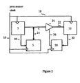
- Figure 1 shows in block diagrammatic form a Lockstep arrangement with duplicated processor circuits;
- Figure 2 shows in block diagrammatic form a simple memory buffer,
- Figure 3 shows a clocked memory buffer according to a first embodiment of the invention;
- Figure 4 shows a clocked memory buffer according to a second embodiment of the invention.
-
- Referring to Figure 1, we see a Lockstep arrangement applied to two processor circuits here labelled A side and B side. The A side circuit comprises a
processor 1 connected to abridge 3 viaprocessor bus 2.Bridges processor bus 2 andbridge 3 to acache memory 4,common memory 5 and to other circuitry (not shown) byperipheral bus 6. The B side processor circuit similarly comprisesprocessor 10,processor bus 11,bridge 12, andcache memory 13.B side processor 10accesses cache memory 13,common memory 5 andperipheral bus 14 viaprocessor bus 11 andbridge 12. Connected betweenperipheral buses 6 on the A side and 14 on the B side isblock 15 comprising Lockstep access control logic. Located betweenB side bridge 12 andcommon memory 5 isisolating device 16. The Lockstep logic further comprises a comparator function (not shown) to monitor the signals generated by the two processor circuits, eg on any or all ofprocessor busses peripheral busses memories - The
common memory 5 is readable from both A andB side processors bridges bridge 3. To achieve thisfunctionality isolating device 16 is required for the data signals between thecommon memory 5 and the Bside bridge device 12.
The Lockstep access control logic ofblock 15 controls accesses to the B sideperipheral bus 14, passing accesses originating from peripheral circuitry (not shown) to the B side processor circuit but stopping any access from the A side processor circuit passing to the B side. The Lockstep access control logic ofblock 15 also prevents access from B sideperipheral bus 14 to A sideperipheral bus 6. - The A side and B side processor circuits share a common processor clock that synchronises the operations of the various components,
i.e. processors processor busses bridges cache memories common memory 5 andisolating device 16. According to the present embodiment of the invention, theperipheral busses block 15 may operate at a different frequency to the processor circuitry of sides A and B, i.e.peripheral buses logic 15 share a second, peripheral clock typically slower than the processor clock. In such cases the peripheral bus interfaces ofbridges - In the following Figures some of the connections shown in Figure 1 have been omitted for clarity.
- Figure 2 shows the circuitry around
common memory 5 in greater detail. Aside bridge 3,B side bridge 12 andcommon memory 5 are all synchronised to the processor clock viaclock lines 18. Address and control information is provided tocommon memory 5 from Aside bridge 3 via address andcontrol lines 20.Isolation device 16 of Figure 1 comprises tri-statebuffer 24 andcontrol logic 28. Data from Aside bridge 3 tocommon memory 5 and fromcommon memory 5 to both A side andB side bridges data lines 22 and (to the B side) via tri-statebuffer 24. - Tri-state
buffer 24 is controlled viacontrol lines 26 bycontrol logic 28, also synchronised to the processor clock and itself provided with control signals fromB side bridge 12 viacontrol lines 30. -
Peripheral busses Processors caches isolation device 16 andcommon memory 5, may all operate at a processor bus clock rate of 100MHz. The PCI peripheral busses and the Lockstep logic ofblock 15 may operate at a peripheral clock rate of 33MHz, (to be exact 100/3 MHZ, i.e. precisely one third the processor bus clock rate and synchronous to the processor clock). - With such a high bus frequency, the performance of the common memory interface and, in particular, the timing characteristics of
isolating device 16 are critical. If an additional buffer is used for isolation then the propagation delay of the buffer is added to the flight time of the data between the common memory and the B side processor circuit, therefore reducing memory bandwidth available to the A and B side circuits. For example, if the isolating device were a simple buffer as shown in Figure 2 then the propagation delay through the buffer would prevent data reaching the B side within one 100MHz processor bus clock cycle. This could be accommodated by reducing the clock speed to compensate, but this would result in an undesirable reduction in overall system performance. - This may be avoided according to a first preferred embodiment of the present invention by the use of a delay stage (for example a clocked buffer) as shown in Figure 3. Figure 3 shows an arrangement similar to that of Figure 2 and features of Figure 3 which are equivalent to features of Figure 2 are given the same reference numerals and will not be further described here. Unlike the arrangement of Figure 2, the
data lines 22 fromcommon memory 5 to tri-statebuffer 24 pass through a clocked buffer 32 (for example a D-type flip-flop) which is also synchronised to the processor clock viaclock line 18. As indicated by the dotted line, clockedbuffer 32 and tri-statebuffer 24 are actually implemented as a single component, ie a tri-state clocked buffer. The clockedbuffer 32 delays the data from the common memory to the B side by one processor bus clock cycle.Clocked buffer 32 is used with set-up and hold requirements determined by the timing requirements ofcommon memory 5 andB side bridge 12. Clockedbuffer 32 retimes the data but presents it at the original data rate hence the bus bandwidth of 100 MHZ (i.e. the processor clock rate) is maintained. - To compensate for data arriving late at
B side bridge 12, theB side processor 10 andbridge 12 are initiated (i.e. taken out of reset) one processor bus clock cycle later than the A side. A suitable reset circuit (not shown), for example comprising a clocked buffer to delay the reset signal to the B side by one processor clock cycle, is provided for this purpose. This means that the B side does not expect the memory data until one processor clock cycle later than the A side. The result is that the A side and B side perform identical functions, albeit one processor clock cycle apart. - The result of this difference in A and B side clocking produces a Pseudo Lockstep mode. By Pseudo Lockstep is meant the devices on sides A and B receive the same inputs and react to them in an identical fashion producing identical outputs but the inputs are applied to and the outputs generated by the A and B sides a fixed number of clock cycles apart.
- Thus, according to this embodiment of the invention, the prior art Lockstep logic is replaced by Pseudo Lockstep logic. The Pseudo Lockstep logic compares the data, address and control signals on the A and B sides in a similar way to the Lockstep logic of the prior art. However, prior to the comparison, the signals from the A side are delayed by the same amount as the time lag introduced by clocked
buffer 32 to the inputs fromcommon memory 5 to the B side circuit. - The Pseudo Lockstep access control logic of
block 15 controls accesses to the B sideperipheral bus 14, passing accesses originating from peripheral circuitry (not shown) to the B side processor circuit, but stopping any access from the side A processor circuit passing to the B side. The Pseudo Lockstep access control logic ofblock 15 also prevents access from B sideperipheral bus 14 to A sideperipheral bus 6. In addition, the Pseudo Lockstep logic ofblock 15 according to the invention delays inputs from the peripheral circuitry (not shown) to the B side processor circuit by the same amount as the time delay introduced byclock buffer 32 to the inputs fromcommon memory 5 to the B side circuit. - The Pseudo Lockstep access control logic of
block 15 will now be described in more detail according to the present embodiment. Isolation of B sideperipheral bus 14 from A sideperipheral bus 6 is achieved bybuffer 40 and data from the A sideperipheral bus 6 is delayed before reachingbuffer 40 by passing through clockedbuffer 42 which is synchronised to the processor clock signal. Access from the A sideperipheral bus 6 to the B sideperipheral bus 14 is controlled by control logic 44 (also synchronised to the processor clock signal) which controls operation ofbuffer 40 via control lines 46. - This approach, in which all inputs to the B side processor circuit must be delayed by the same amount (e.g. one processor clock), may cause problems with the interface between
B side bridge 12 and the peripheral bus if running at different clock rates because it would mean, to take the example cited above, attempting to retime the 33MHz PCI bus with a 100MHz clock, resulting in difficult timing problems. - According to a second preferred embodiment of the present invention, the time lag introduced in data from
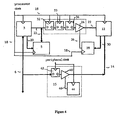
common memory 5 to the B side is increased to 3 processor bus clock cycles, equal to one peripheral (in this case PCI bus) clock cycle. It is now necessary to delay the other inputs toB side bridge 12 by one peripheral clock cycle, which is much simpler. - As shown in Figure 4, the single clocked
buffer 32 of Figure 3 is replaced by a number (in this example 3) of such buffers 32-34 connected in series. As a result the data through thebuffer 24 is delayed by a number of (in this example 3) processor clock cycles equivalent to one or more whole peripheral clock cycles. As in Figure 3, the dotted line indicates thattri-state buffer 24 is implemented as part of clocked buffers 32-34, ie clockedbuffer 34 andtri-state buffer 24 are implemented as a single tri-state clocked buffer. This means that data arriving at theB side bridge 12 suffers a time lag of one or more whole peripheral clock cycles compared to the data arriving at the A side bridge. Again, de-assertion of the B side reset is delayed by the amount of the time lag, and all and all inputs into the B side are delayed by the same amount. The Pseudo Lockstep access control logic ofblock 15 according to the present embodiment is essentially similar to that described above with respect to the first embodiment. Hence the features of the Pseudo Lockstep logic of Figure 4 bear the same reference numerals as the equivalent features of Figure 3. The important difference is that, whereas the Pseudo Lockstep logic of the first embodiment is synchronised to the processor clock signal, the Pseudo Lockstep logic of the present embodiment is synchronised to the peripheral clock signal (in this example the 33 MHZ PCI clock). - It would be obvious to the skilled worker in the field that the scope of the invention is not limited to the specific embodiments described here. For example, the present invention applies equally to other combinations of processor and peripheral clock rates. Although described here with reference to processor circuits, the invention applies equally to other sorts of digital or logic circuits, including digital signal processors. References to common memory include any read-write devices including registers and mass storage. Other forms of delay stage which may be used in implementing the invention include delay lines.
Claims (8)
- A data processing system comprising
a common memory (5),
a first and second data processor circuit (10, 1), each arranged to execute the same sequence of operational steps and each connected to the common memory (5),
an isolating device (24, 32, 33, 34) connected between the first data processor circuit (10) and the common memory (5) and arranged to restrict access by the first data processor circuit (10) to the common memory (5) to read-only access,
in which the first data processor circuit (10) is arranged to execute each operational step a set time period later than the second data processor circuit (1);
characterised by a first and second peripheral bus (14, 6), the second peripheral bus (6) arranged to connect the second processor circuit (1) to further devices and arranged to connect the first processor circuit (10) via the first peripheral bus (14) to the further devices,
and an access controller (15) arranged to introduce a time delay into signals passing from the further devices to the first processor circuit (10). - The data processing system of Claim 1 also comprising a comparator arranged to compare the operations of the data processor circuits (1, 10) in which the comparator is arranged to compensate for the time delay between the execution of each operational step by the second and the first data processor circuits (1, 10) when making the comparison.
- The data processing system of any one of Claims 1 and 2 in which all inputs received by the first data processor circuit (10) are delayed by the duration of the time period.
- The data processing system of Claim 1 in which the access controller (15) is arranged to prevent communication between the first and the second processor circuits (1, 10) via the peripheral busses (6, 14) and to prevent signals from the first processor circuit (10) passing to the further devices.
- The data processing system of any one of the above claims in which the first and second processor circuits (1, 10) are connected to a first clock signal (18) for synchronisation.
- The data processing system of Claim 5 in which the peripheral busses (6, 14) and the access controller (15) are connected to a second clock signal for synchronisation and in which, in operation, the frequency of the first clock signal (18) is higher than the frequency of the second clock signal.
- The data processing system of Claim 5 or 6 in which the isolating device (24, 32, 33, 34) delays the data by an integral number of first clock cycles.
- The data processing system of Claim 7 as dependant from Claim 6 in which the isolating device (24, 32, 33, 34) delays the data by an integral number of second clock cycles.
Applications Claiming Priority (2)
| Application Number | Priority Date | Filing Date | Title |
|---|---|---|---|
| GB9817598 | 1998-08-13 | ||
| GB9817598A GB2340627B (en) | 1998-08-13 | 1998-08-13 | Data processing system |
Publications (3)
| Publication Number | Publication Date |
|---|---|
| EP0980040A2 EP0980040A2 (en) | 2000-02-16 |
| EP0980040A3 EP0980040A3 (en) | 2000-08-09 |
| EP0980040B1 true EP0980040B1 (en) | 2003-06-11 |
Family
ID=10837155
Family Applications (1)
| Application Number | Title | Priority Date | Filing Date |
|---|---|---|---|
| EP99306330A Expired - Lifetime EP0980040B1 (en) | 1998-08-13 | 1999-08-11 | Pseudo lockstep data processing system |
Country Status (8)
| Country | Link |
|---|---|
| US (1) | US6519710B1 (en) |
| EP (1) | EP0980040B1 (en) |
| CN (1) | CN1154944C (en) |
| DE (1) | DE69908717T2 (en) |
| ES (1) | ES2199527T3 (en) |
| GB (1) | GB2340627B (en) |
| HK (1) | HK1024067A1 (en) |
| RU (1) | RU99118019A (en) |
Families Citing this family (19)
| Publication number | Priority date | Publication date | Assignee | Title |
|---|---|---|---|---|
| JP3982353B2 (en) * | 2002-07-12 | 2007-09-26 | 日本電気株式会社 | Fault tolerant computer apparatus, resynchronization method and resynchronization program |
| DE60334837D1 (en) * | 2002-11-27 | 2010-12-16 | Rhode Island Education | SYSTEM AND METHOD FOR IMPROVING PERFORMANCE OF DIGITAL SYSTEMS |
| US7287184B2 (en) * | 2003-09-16 | 2007-10-23 | Rockwell Automation Technologies, Inc. | High speed synchronization in dual-processor safety controller |
| US7546441B1 (en) | 2004-08-06 | 2009-06-09 | Xilinx, Inc. | Coprocessor interface controller |
| US7590823B1 (en) | 2004-08-06 | 2009-09-15 | Xilinx, Inc. | Method and system for handling an instruction not supported in a coprocessor formed using configurable logic |
| US7346759B1 (en) | 2004-08-06 | 2008-03-18 | Xilinx, Inc. | Decoder interface |
| US7243212B1 (en) * | 2004-08-06 | 2007-07-10 | Xilinx, Inc. | Processor-controller interface for non-lock step operation |
| US7590822B1 (en) | 2004-08-06 | 2009-09-15 | Xilinx, Inc. | Tracking an instruction through a processor pipeline |
| US20070294559A1 (en) * | 2004-10-25 | 2007-12-20 | Thomas Kottke | Method and Device for Delaying Access to Data and/or Instructions of a Multiprocessor System |
| JP2008518308A (en) * | 2004-10-25 | 2008-05-29 | ローベルト ボッシュ ゲゼルシャフト ミット ベシュレンクテル ハフツング | Method and data distribution unit for distributing data in a multiprocessor system |
| JP3897046B2 (en) * | 2005-01-28 | 2007-03-22 | 横河電機株式会社 | Information processing apparatus and information processing method |
| US20070038849A1 (en) * | 2005-08-11 | 2007-02-15 | Rajiv Madampath | Computing system and method |
| US20090177866A1 (en) * | 2008-01-08 | 2009-07-09 | Choate Michael L | System and method for functionally redundant computing system having a configurable delay between logically synchronized processors |
| US8819485B2 (en) | 2012-03-12 | 2014-08-26 | Infineon Technologies Ag | Method and system for fault containment |
| CN102970029A (en) * | 2012-11-06 | 2013-03-13 | 北京广利核系统工程有限公司 | High-safety digital quantity signal acquisition circuit |
| US9912754B2 (en) * | 2015-05-01 | 2018-03-06 | GM Global Technology Operations LLC | Vehicular data isolation device |
| US10002056B2 (en) | 2015-09-15 | 2018-06-19 | Texas Instruments Incorporated | Integrated circuit chip with cores asymmetrically oriented with respect to each other |
| US10740167B2 (en) * | 2016-12-07 | 2020-08-11 | Electronics And Telecommunications Research Institute | Multi-core processor and cache management method thereof |
| CN110175091B (en) * | 2018-12-11 | 2023-06-23 | 中国航空工业集团公司西安航空计算技术研究所 | Method, device and circuit for synchronizing signals between nodes under Lockstep architecture |
Citations (1)
| Publication number | Priority date | Publication date | Assignee | Title |
|---|---|---|---|---|
| US5231640A (en) * | 1990-07-20 | 1993-07-27 | Unisys Corporation | Fault tolerant processor/memory architecture |
Family Cites Families (9)
| Publication number | Priority date | Publication date | Assignee | Title |
|---|---|---|---|---|
| DE2644205A1 (en) * | 1976-09-30 | 1978-04-06 | Agfa Gevaert Ag | PHOTOGRAPHIC CAMERA WITH A DIGITAL EXPOSURE CONTROL DEVICE |
| SE397013B (en) * | 1976-12-17 | 1977-10-10 | Ellemtel Utvecklings Ab | METHOD AND DEVICE FOR TRANSFERRING DATA INFORMATION TO TWO PARALLEL WORKING COMPUTER PARTS |
| US4358823A (en) * | 1977-03-25 | 1982-11-09 | Trw, Inc. | Double redundant processor |
| US4164787A (en) * | 1977-11-09 | 1979-08-14 | Bell Telephone Laboratories, Incorporated | Multiple microprocessor intercommunication arrangement |
| US4540898A (en) * | 1983-03-07 | 1985-09-10 | Motorola, Inc. | Clocked buffer circuit using a self-bootstrapping transistor |
| EP0528538B1 (en) * | 1991-07-18 | 1998-12-23 | Tandem Computers Incorporated | Mirrored memory multi processor system |
| JPH05128080A (en) * | 1991-10-14 | 1993-05-25 | Mitsubishi Electric Corp | Information processor |
| US5604754A (en) * | 1995-02-27 | 1997-02-18 | International Business Machines Corporation | Validating the synchronization of lock step operated circuits |
| GB2317032A (en) * | 1996-09-07 | 1998-03-11 | Motorola Gmbh | Microprocessor fail-safe system |
-
1998
- 1998-08-13 GB GB9817598A patent/GB2340627B/en not_active Expired - Fee Related
-
1999
- 1999-08-11 EP EP99306330A patent/EP0980040B1/en not_active Expired - Lifetime
- 1999-08-11 DE DE69908717T patent/DE69908717T2/en not_active Expired - Lifetime
- 1999-08-11 ES ES99306330T patent/ES2199527T3/en not_active Expired - Lifetime
- 1999-08-12 RU RU99118019/09A patent/RU99118019A/en not_active Application Discontinuation
- 1999-08-12 US US09/373,278 patent/US6519710B1/en not_active Expired - Lifetime
- 1999-08-13 CN CNB991197976A patent/CN1154944C/en not_active Expired - Fee Related
-
2000
- 2000-05-22 HK HK00103021A patent/HK1024067A1/en not_active IP Right Cessation
Patent Citations (1)
| Publication number | Priority date | Publication date | Assignee | Title |
|---|---|---|---|---|
| US5231640A (en) * | 1990-07-20 | 1993-07-27 | Unisys Corporation | Fault tolerant processor/memory architecture |
Also Published As
| Publication number | Publication date |
|---|---|
| EP0980040A2 (en) | 2000-02-16 |
| US6519710B1 (en) | 2003-02-11 |
| CN1154944C (en) | 2004-06-23 |
| CN1248748A (en) | 2000-03-29 |
| GB9817598D0 (en) | 1998-10-07 |
| ES2199527T3 (en) | 2004-02-16 |
| HK1024067A1 (en) | 2000-09-29 |
| DE69908717T2 (en) | 2003-12-11 |
| GB2340627B (en) | 2000-10-04 |
| GB2340627A (en) | 2000-02-23 |
| RU99118019A (en) | 2001-08-27 |
| EP0980040A3 (en) | 2000-08-09 |
| DE69908717D1 (en) | 2003-07-17 |
Similar Documents
| Publication | Publication Date | Title |
|---|---|---|
| EP0980040B1 (en) | Pseudo lockstep data processing system | |
| KR100566339B1 (en) | Fault-tolerant computer system, re-synchronization method thereof and computer-readable storage medium having re-synchronization program thereof | |
| US5185877A (en) | Protocol for transfer of DMA data | |
| US5758136A (en) | Method for dynamically switching between a plurality of clock sources upon detection of phase alignment therefor and disabling all other clock sources | |
| US5452443A (en) | Multi-processor system with fault detection | |
| US5153881A (en) | Method of handling errors in software | |
| US5001712A (en) | Diagnostic error injection for a synchronous bus system | |
| US5068851A (en) | Apparatus and method for documenting faults in computing modules | |
| US4835728A (en) | Deterministic clock control apparatus for a data processing system | |
| US5251227A (en) | Targeted resets in a data processor including a trace memory to store transactions | |
| US5048022A (en) | Memory device with transfer of ECC signals on time division multiplexed bidirectional lines | |
| US5163138A (en) | Protocol for read write transfers via switching logic by transmitting and retransmitting an address | |
| US5065312A (en) | Method of converting unique data to system data | |
| JPH01154242A (en) | Double-zone failure-proof computer system | |
| US7653764B2 (en) | Fault-tolerant computer and method of controlling data transmission | |
| EP0411805B1 (en) | Bulk memory transfer during resync | |
| US6047382A (en) | Processor with short set-up and hold times for bus signals | |
| US10769038B2 (en) | Counter circuitry and methods including a master counter providing initialization data and fault detection data and wherein a threshold count difference of a fault detection count is dependent upon the fault detection data | |
| EP0416732B1 (en) | Targeted resets in a data processor | |
| US6892345B1 (en) | Integrated circuit including duplicated synchronous and asynchronous components | |
| US5192914A (en) | Clock control circuit for suppressing clock pulses | |
| US6463551B1 (en) | Debug circuit and microcomputer incorporating debug circuit | |
| US6928575B2 (en) | Apparatus for controlling and supplying in phase clock signals to components of an integrated circuit with a multiprocessor architecture | |
| JPH1011309A (en) | Processor output comparing method and computer system | |
| JP2756445B2 (en) | Asynchronous circuit reset method |
Legal Events
| Date | Code | Title | Description |
|---|---|---|---|
| PUAI | Public reference made under article 153(3) epc to a published international application that has entered the european phase |
Free format text: ORIGINAL CODE: 0009012 |
|
| AK | Designated contracting states |
Kind code of ref document: A2 Designated state(s): DE ES FR IT |
|
| AX | Request for extension of the european patent |
Free format text: AL;LT;LV;MK;RO;SI |
|
| PUAL | Search report despatched |
Free format text: ORIGINAL CODE: 0009013 |
|
| AK | Designated contracting states |
Kind code of ref document: A3 Designated state(s): AT BE CH CY DE DK ES FI FR GB GR IE IT LI LU MC NL PT SE |
|
| AX | Request for extension of the european patent |
Free format text: AL;LT;LV;MK;RO;SI |
|
| RIN1 | Information on inventor provided before grant (corrected) |
Inventor name: GURAYA, PARMINDER SINGH Inventor name: SAUNDERS, JONATHAN MARK Inventor name: STRANGE, ROBERT GEORGE |
|
| 17P | Request for examination filed |
Effective date: 20010122 |
|
| AKX | Designation fees paid |
Free format text: DE ES FR IT |
|
| 17Q | First examination report despatched |
Effective date: 20020718 |
|
| GRAH | Despatch of communication of intention to grant a patent |
Free format text: ORIGINAL CODE: EPIDOS IGRA |
|
| RTI1 | Title (correction) |
Free format text: PSEUDO LOCKSTEP DATA PROCESSING SYSTEM |
|
| GRAA | (expected) grant |
Free format text: ORIGINAL CODE: 0009210 |
|
| GRAH | Despatch of communication of intention to grant a patent |
Free format text: ORIGINAL CODE: EPIDOS IGRA |
|
| AK | Designated contracting states |
Designated state(s): DE ES FR IT |
|
| REF | Corresponds to: |
Ref document number: 69908717 Country of ref document: DE Date of ref document: 20030717 Kind code of ref document: P |
|
| PGFP | Annual fee paid to national office [announced via postgrant information from national office to epo] |
Ref country code: ES Payment date: 20030926 Year of fee payment: 5 |
|
| ET | Fr: translation filed | ||
| REG | Reference to a national code |
Ref country code: ES Ref legal event code: FG2A Ref document number: 2199527 Country of ref document: ES Kind code of ref document: T3 |
|
| PLBE | No opposition filed within time limit |
Free format text: ORIGINAL CODE: 0009261 |
|
| STAA | Information on the status of an ep patent application or granted ep patent |
Free format text: STATUS: NO OPPOSITION FILED WITHIN TIME LIMIT |
|
| 26N | No opposition filed |
Effective date: 20040312 |
|
| REG | Reference to a national code |
Ref country code: FR Ref legal event code: TP |
|
| PG25 | Lapsed in a contracting state [announced via postgrant information from national office to epo] |
Ref country code: ES Free format text: LAPSE BECAUSE OF NON-PAYMENT OF DUE FEES Effective date: 20040812 |
|
| REG | Reference to a national code |
Ref country code: ES Ref legal event code: FD2A Effective date: 20040812 |
|
| REG | Reference to a national code |
Ref country code: FR Ref legal event code: TP |
|
| PGFP | Annual fee paid to national office [announced via postgrant information from national office to epo] |
Ref country code: IT Payment date: 20070829 Year of fee payment: 9 |
|
| PG25 | Lapsed in a contracting state [announced via postgrant information from national office to epo] |
Ref country code: IT Free format text: LAPSE BECAUSE OF NON-PAYMENT OF DUE FEES Effective date: 20080811 |
|
| PGFP | Annual fee paid to national office [announced via postgrant information from national office to epo] |
Ref country code: DE Payment date: 20140827 Year of fee payment: 16 |
|
| PGFP | Annual fee paid to national office [announced via postgrant information from national office to epo] |
Ref country code: FR Payment date: 20140818 Year of fee payment: 16 |
|
| REG | Reference to a national code |
Ref country code: DE Ref legal event code: R119 Ref document number: 69908717 Country of ref document: DE |
|
| REG | Reference to a national code |
Ref country code: FR Ref legal event code: ST Effective date: 20160429 |
|
| PG25 | Lapsed in a contracting state [announced via postgrant information from national office to epo] |
Ref country code: DE Free format text: LAPSE BECAUSE OF NON-PAYMENT OF DUE FEES Effective date: 20160301 |
|
| PG25 | Lapsed in a contracting state [announced via postgrant information from national office to epo] |
Ref country code: FR Free format text: LAPSE BECAUSE OF NON-PAYMENT OF DUE FEES Effective date: 20150831 |