EP0979963B1 - Brush seal segment - Google Patents
Brush seal segment Download PDFInfo
- Publication number
- EP0979963B1 EP0979963B1 EP99306175A EP99306175A EP0979963B1 EP 0979963 B1 EP0979963 B1 EP 0979963B1 EP 99306175 A EP99306175 A EP 99306175A EP 99306175 A EP99306175 A EP 99306175A EP 0979963 B1 EP0979963 B1 EP 0979963B1
- Authority
- EP
- European Patent Office
- Prior art keywords
- backing plate
- rim
- brush
- generally
- upstream
- Prior art date
- Legal status (The legal status is an assumption and is not a legal conclusion. Google has not performed a legal analysis and makes no representation as to the accuracy of the status listed.)
- Expired - Lifetime
Links
- 238000011144 upstream manufacturing Methods 0.000 claims description 5
- 238000010276 construction Methods 0.000 description 2
- 239000000446 fuel Substances 0.000 description 2
- 230000001052 transient effect Effects 0.000 description 2
- 229910000531 Co alloy Inorganic materials 0.000 description 1
- -1 but not limited to Inorganic materials 0.000 description 1
- 239000002184 metal Substances 0.000 description 1
- 229910052751 metal Inorganic materials 0.000 description 1
- 229910001092 metal group alloy Inorganic materials 0.000 description 1
- 238000011084 recovery Methods 0.000 description 1
- 239000010935 stainless steel Substances 0.000 description 1
- 229910001220 stainless steel Inorganic materials 0.000 description 1
- 238000003466 welding Methods 0.000 description 1
Images

Classifications
-
- F—MECHANICAL ENGINEERING; LIGHTING; HEATING; WEAPONS; BLASTING
- F16—ENGINEERING ELEMENTS AND UNITS; GENERAL MEASURES FOR PRODUCING AND MAINTAINING EFFECTIVE FUNCTIONING OF MACHINES OR INSTALLATIONS; THERMAL INSULATION IN GENERAL
- F16J—PISTONS; CYLINDERS; SEALINGS
- F16J15/00—Sealings
- F16J15/16—Sealings between relatively-moving surfaces
- F16J15/32—Sealings between relatively-moving surfaces with elastic sealings, e.g. O-rings
- F16J15/3284—Sealings between relatively-moving surfaces with elastic sealings, e.g. O-rings characterised by their structure; Selection of materials
- F16J15/3288—Filamentary structures, e.g. brush seals
-
- F—MECHANICAL ENGINEERING; LIGHTING; HEATING; WEAPONS; BLASTING
- F01—MACHINES OR ENGINES IN GENERAL; ENGINE PLANTS IN GENERAL; STEAM ENGINES
- F01D—NON-POSITIVE DISPLACEMENT MACHINES OR ENGINES, e.g. STEAM TURBINES
- F01D1/00—Non-positive-displacement machines or engines, e.g. steam turbines
Definitions
- the present invention relates generally to seals, and more particularly to a brush seal segment.
- Rotary machines include, without limitation, turbines for steam turbines and compressors and turbines for gas turbines.
- a steam turbine has a steam path which typically includes, in serial-flow relationship, a steam inlet, a turbine, and a steam outlet.
- a gas turbine has a gas path which typically includes, in serial-flow relationship, an air intake (or inlet), a compressor, a combustor, a turbine, and a gas outlet (or exhaust nozzle). Gas or steam leakage, either out of the gas or steam path or into the gas or steam path, from an area of higher pressure to an area of lower pressure, is generally undesirable.
- gas-path leakage in the turbine or compressor area of a gas turbine, between the rotor of the turbine or compressor and the circumferentially surrounding turbine or compressor casing will lower the efficiency of the gas turbine leading to increased fuel costs.
- steam-path leakage in the turbine area of a steam turbine, between the rotor of the turbine and the circumferentially surrounding casing will lower the efficiency of the steam turbine leading to increased fuel costs.
- Annular brush seals have been proposed for use between a rotor and a surrounding casing in gas and steam turbines.
- the annular brush seal includes an annular backing plate which may terminate in the shape of an annular labyrinth-seal tooth having a sloped downstream-facing surface and also includes bristles which are canted at typically a forty-five degree angle with respect to a radius line.
- a gas or steam turbine brush seal is made up of circumferentially-arrayed and radially-cut brush seal segments. The angled bristles create an exposed area at one circumferential edge of each segment. The labyrinth-seal tooth reduces leakage through this exposed area.
- the brush seal segment of the invention includes a brush-seal backing plate and brush-seal bristles.
- the backing plate has a shape of generally an annular segment of a circular ring which has a longitudinal axis.
- the backing plate has generally upstream-facing and downstream-facing surfaces with the upstream-facing surface aligned generally perpendicular to the axis.
- the backing plate has generally radially-aligned first and second edges circumferentially bounding together the upstream-facing and downstream-facing surfaces.
- the backing plate has a rim radially-inwardly bounding together the upstream-facing and downstream-facing surfaces, wherein the rim has first and second portions, wherein the first portion circumferentially extends from the first edge to the second portion, wherein the second portion is located near the second edge, and wherein the second portion extends radially inward further than the first portion.
- the bristles generally abut the upstream-facing surface and are each canted at a generally-identical angle with respect to a corresponding radius line extending outward to each of the bristles.
- the bristles are generally entirely circumferentially contained between a radius line extending outward to the first edge and a radius line extending outward to the second edge, and the bristles extend inwardly beyond said rim from generally the first portion only of the rim.
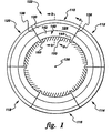
- Figures 1-3 schematically show a first preferred embodiment of the brush seal segment 110 of the present invention together with five other identical brush seal segments 112, 114, 116, 118, and 120 all circumferentially arrayed to define an annular brush seal 122.
- the annular brush seal 122 is for use in a rotary machine (not shown in the figures) with the brush seal being disposed in the annular gap between a rotor and a surrounding casing of the rotary machine and with the brush seal being attached to the casing.
- a preferred rotary machine is a steam turbine or a gas turbine.
- the brush seal segment 110 includes a brush seal backing plate 124.
- the backing plate 124 has a shape of generally an annular segment of a circular ring (e.g., the brush seal 112) having a longitudinal axis 126 (seen on end as a dot in Figure 1 and seen as a dashed line in Figures 2 and 3).
- the backing plate 124 has generally upstream-facing and downstream-facing surfaces 128 and 130 with the upstream-facing surface 128 aligned generally perpendicular to the axis 126.
- an upstream-facing surface is defined as a surface which faces generally toward the higher-pressure side 132, and away from the lower-pressure side 134, of the seal segment 110
- a downstream-facing surface is defined as a surface which faces generally toward the lower-pressure side 134, and away from the higher-pressure side 132, of the seal segment 110.
- the backing plate 124 has generally radially-aligned first and second edges 136 and 138 circumferentially bounding (i.e., attaching) together the upstream-facing and downstream-facing surfaces 128 and 130.
- the backing plate 124 also has a rim 140 radially-inwardly bounding (i.e., attaching) together the upstream-facing and downstream-facing surfaces 128 and 130.
- the rim 140 circumferentially extends from the first edge 136 to the second edge 138.
- the rim 140 has first and second portions 142 and 144.
- the first portion 142 of the rim 140 circumferentially extends from the first edge 136 to the second portion 144.
- the second portion 144 is disposed proximate the second edge 138, and the second portion 144 extends radially inward further than the first portion 142.
- the second portion 144 of the rim 140 of the backing plate 124 has a shape of a labyrinth-seal tooth 146 when the backing plate 124 is viewed in a first cross section (see Figure 2) taken by a cutting plane defined by the intersection of the axis 126 and a radius line which extends radially outward (from the axis 126) to the second portion 144.
- the first portion 142 of the rim 140 of the backing plate 124 has a shape other than that of a labyrinth-seal tooth when the backing plate 124 is viewed in a second cross section (see Figure 3) taken by a cutting plane defined by the intersection of the axis 126 and a radius line (from the axis 126) which extends radially outward to the first portion 142.
- the first portion 142 of the rim 140 of the backing plate 124 has a shape of a line 148 which is generally parallel to the axis 126 when the backing plate 124 is viewed in the second cross section (see Figure 3).
- the brush seal segment 110 also includes brush-seal bristles 150 generally abutting the upstream-facing surface 128 of the backing plate 124.
- the bristles 150 are each canted at a generally-identical angle with respect to a corresponding radius line extending outward (from the axis 126) to each of the bristles 150.
- the angle of the bristles 150 is generally forty-five degrees.
- the bristles 150 are generally entirely circumferentially contained between a radius line extending outward (from the axis 126) to the first edge 136 and a radius line extending outward (from the axis 126) to the second edge 138.
- the brush seal segment 110 including its just-described bristles 150 and previously-described backing plate 124, is said to be radially cut.
- the bristles 150 extend inwardly beyond the rim 140 from generally the first portion 142 only of the rim 140.
- generally no bristles 150 extend from the second portion 144 of the rim 140 because of the bristle angle.
- the brush seal segment 110 of the present invention offers advantages, as can be appreciated by those skilled in the art. Only the small second portion 144 of the rim 140 will deform when the brush seal segment 110 experiences a transient rotor rub. Since generally no bristles 150 extend from the second portion 144 of the rim 140 because of the bristle angle, the deformed rim generally will not interfere with the bristles 150 even if the rim 140 deforms longitudinally toward the upstream-facing surface 128 of the backing plate 124, and thus the bristles can recover from a rotor rub.
- the backing plate 124 including the rim 140 is of monolithic construction and consists essentially of metal or metal alloy such as, but not limited to, stainless steel.
- the bristles 150 typically consist essentially of metal-wire or ceramic-wire bristles such as, but not limited to, cobalt-based-alloy wire bristles.
- metal-wire bristles 150 are attached to the backing plate 124 by welding (such weldment omitted from the figures for clarity).
- the brush seal segment 110 further includes an upstream plate 152 as is known to the artisan.
Landscapes
- Engineering & Computer Science (AREA)
- General Engineering & Computer Science (AREA)
- Mechanical Engineering (AREA)
- Turbine Rotor Nozzle Sealing (AREA)
- Sealing Devices (AREA)
- Sealing Using Fluids, Sealing Without Contact, And Removal Of Oil (AREA)
Description
- The present invention relates generally to seals, and more particularly to a brush seal segment.
- Rotary machines include, without limitation, turbines for steam turbines and compressors and turbines for gas turbines. A steam turbine has a steam path which typically includes, in serial-flow relationship, a steam inlet, a turbine, and a steam outlet. A gas turbine has a gas path which typically includes, in serial-flow relationship, an air intake (or inlet), a compressor, a combustor, a turbine, and a gas outlet (or exhaust nozzle). Gas or steam leakage, either out of the gas or steam path or into the gas or steam path, from an area of higher pressure to an area of lower pressure, is generally undesirable. For example, gas-path leakage in the turbine or compressor area of a gas turbine, between the rotor of the turbine or compressor and the circumferentially surrounding turbine or compressor casing, will lower the efficiency of the gas turbine leading to increased fuel costs. Also, steam-path leakage in the turbine area of a steam turbine, between the rotor of the turbine and the circumferentially surrounding casing, will lower the efficiency of the steam turbine leading to increased fuel costs.
- Annular brush seals have been proposed for use between a rotor and a surrounding casing in gas and steam turbines. The annular brush seal includes an annular backing plate which may terminate in the shape of an annular labyrinth-seal tooth having a sloped downstream-facing surface and also includes bristles which are canted at typically a forty-five degree angle with respect to a radius line. A gas or steam turbine brush seal is made up of circumferentially-arrayed and radially-cut brush seal segments. The angled bristles create an exposed area at one circumferential edge of each segment. The labyrinth-seal tooth reduces leakage through this exposed area. Examples of such brush seals are described in US-A-5,749,584 and US-A-5,401,036. Unfortunately, Applicants have found that radial contact of the labyrinth-seal tooth with the rotor during startup deformed the annular tooth into large circumferential areas of bristles preventing recovery of these bristles once the rotor reached steady-state operating conditions. The unrecovered bristles allowed large leakage.
- The brush seal segment of the invention includes a brush-seal backing plate and brush-seal bristles. The backing plate has a shape of generally an annular segment of a circular ring which has a longitudinal axis. The backing plate has generally upstream-facing and downstream-facing surfaces with the upstream-facing surface aligned generally perpendicular to the axis. The backing plate has generally radially-aligned first and second edges circumferentially bounding together the upstream-facing and downstream-facing surfaces. The backing plate has a rim radially-inwardly bounding together the upstream-facing and downstream-facing surfaces, wherein the rim has first and second portions, wherein the first portion circumferentially extends from the first edge to the second portion, wherein the second portion is located near the second edge, and wherein the second portion extends radially inward further than the first portion. The bristles generally abut the upstream-facing surface and are each canted at a generally-identical angle with respect to a corresponding radius line extending outward to each of the bristles. The bristles are generally entirely circumferentially contained between a radius line extending outward to the first edge and a radius line extending outward to the second edge, and the bristles extend inwardly beyond said rim from generally the first portion only of the rim.
- Several benefits and advantages are derived from the invention. Only the small second portion of the rim will deform when the brush seal segment experiences a transient rotor rub. Since generally no bristles extend from the second portion of the rim because of the bristle angle, the deformed rim generally will not interfere with the bristles even if the rim deforms longitudinally toward the upstream-facing surface of the backing plate, and thus the bristles can recover from a rotor rub.
- Embodiments of the invention will now be described, by way of example, with reference to the accompanying drawings, in which:
- Figure 1 is a schematic upstream-facing view of a first preferred embodiment of the brush seal segment of the invention shown circumferentially arrayed with other identical brush seal segments to define a brush seal;
- Figure 2 is a cross-sectional view taken along lines 2-2 of Figure 1; and
- Figure 3 is a cross-sectional view taken along lines 3-3 of Figure 1.
-
- Referring now to the drawings, Figures 1-3 schematically show a first preferred embodiment of the
brush seal segment 110 of the present invention together with five other identicalbrush seal segments annular brush seal 122. Preferably, theannular brush seal 122 is for use in a rotary machine (not shown in the figures) with the brush seal being disposed in the annular gap between a rotor and a surrounding casing of the rotary machine and with the brush seal being attached to the casing. A preferred rotary machine is a steam turbine or a gas turbine. - The
brush seal segment 110 includes a brushseal backing plate 124. As seen in Figure 1, thebacking plate 124 has a shape of generally an annular segment of a circular ring (e.g., the brush seal 112) having a longitudinal axis 126 (seen on end as a dot in Figure 1 and seen as a dashed line in Figures 2 and 3). Thebacking plate 124 has generally upstream-facing and downstream-facingsurfaces surface 128 aligned generally perpendicular to theaxis 126. For the purpose of describing the invention, an upstream-facing surface is defined as a surface which faces generally toward the higher-pressure side 132, and away from the lower-pressure side 134, of theseal segment 110, and a downstream-facing surface is defined as a surface which faces generally toward the lower-pressure side 134, and away from the higher-pressure side 132, of theseal segment 110. Thebacking plate 124 has generally radially-aligned first andsecond edges surfaces - The
backing plate 124 also has arim 140 radially-inwardly bounding (i.e., attaching) together the upstream-facing and downstream-facingsurfaces rim 140 circumferentially extends from thefirst edge 136 to thesecond edge 138. Therim 140 has first andsecond portions first portion 142 of therim 140 circumferentially extends from thefirst edge 136 to thesecond portion 144. Thesecond portion 144 is disposed proximate thesecond edge 138, and thesecond portion 144 extends radially inward further than thefirst portion 142. - Preferably, the
second portion 144 of therim 140 of thebacking plate 124 has a shape of a labyrinth-seal tooth 146 when thebacking plate 124 is viewed in a first cross section (see Figure 2) taken by a cutting plane defined by the intersection of theaxis 126 and a radius line which extends radially outward (from the axis 126) to thesecond portion 144. It is also preferred that thefirst portion 142 of therim 140 of thebacking plate 124 has a shape other than that of a labyrinth-seal tooth when thebacking plate 124 is viewed in a second cross section (see Figure 3) taken by a cutting plane defined by the intersection of theaxis 126 and a radius line (from the axis 126) which extends radially outward to thefirst portion 142. In an exemplary enablement, thefirst portion 142 of therim 140 of thebacking plate 124 has a shape of aline 148 which is generally parallel to theaxis 126 when thebacking plate 124 is viewed in the second cross section (see Figure 3). - The
brush seal segment 110 also includes brush-seal bristles 150 generally abutting the upstream-facingsurface 128 of thebacking plate 124. Thebristles 150 are each canted at a generally-identical angle with respect to a corresponding radius line extending outward (from the axis 126) to each of thebristles 150. Preferably, the angle of thebristles 150 is generally forty-five degrees. Thebristles 150 are generally entirely circumferentially contained between a radius line extending outward (from the axis 126) to thefirst edge 136 and a radius line extending outward (from the axis 126) to thesecond edge 138. Thus, thebrush seal segment 110, including its just-describedbristles 150 and previously-describedbacking plate 124, is said to be radially cut. Thebristles 150 extend inwardly beyond therim 140 from generally thefirst portion 142 only of therim 140. Thus, generally nobristles 150 extend from thesecond portion 144 of therim 140 because of the bristle angle. - The
brush seal segment 110 of the present invention offers advantages, as can be appreciated by those skilled in the art. Only the smallsecond portion 144 of therim 140 will deform when thebrush seal segment 110 experiences a transient rotor rub. Since generally nobristles 150 extend from thesecond portion 144 of therim 140 because of the bristle angle, the deformed rim generally will not interfere with thebristles 150 even if therim 140 deforms longitudinally toward the upstream-facingsurface 128 of thebacking plate 124, and thus the bristles can recover from a rotor rub. - In a typical construction, the
backing plate 124 including therim 140 is of monolithic construction and consists essentially of metal or metal alloy such as, but not limited to, stainless steel. Thebristles 150 typically consist essentially of metal-wire or ceramic-wire bristles such as, but not limited to, cobalt-based-alloy wire bristles. Preferably, metal-wire bristles 150 are attached to thebacking plate 124 by welding (such weldment omitted from the figures for clarity). Commonly, thebrush seal segment 110 further includes anupstream plate 152 as is known to the artisan.
Claims (13)
- A brush seal segment (110) comprising:a) a brush-seal backing plate (124) having a shape of generally an annular segment of a circular ring, said ring having a longitudinal axis (126), said backing plate having generally upstream-facing (128) and downstream-facing surfaces (130), said upstream-facing surface being aligned generally perpendicular to said axis, said backing plate having generally radially-aligned first (136) and second edges (138) circumferentially bounding together said upstream-facing and downstream-facing surfaces, said backing plate having a rim (140) radially-inwardly bounding together said upstream-facing and downstream-facing surfaces, andb) brush-seal bristles (150) generally abutting said upstream-facing surface, said bristles each canted at a generally-identical angle with respect to a corresponding radius line extending outward to each of said bristles, said bristles generally entirely circumferentially contained between a radius line extending outward to said first edge (136) and a radius line extending outward to said second edge (138), and said bristles extending inwardly beyond said rim from generally said first portion only of said rim, characterised in that
said rim has first (142) and second (144) portions, said first portion (142) circumferentially extending from said first edge to said second portion(144), and said second portion disposed only proximate said second edge, wherein said second portion extends radially inward further than said first portion. - The brush seal segment (110) of claim 1, wherein said second portion (144) of said rim (140) of said backing plate (124) has a shape of a labyrinth-seal tooth (146) when said backing plate is viewed in a first cross section taken by a cutting plane defined by the intersection of said axis (126) and a radius line which extends radially outward to said second portion.
- The brush seal segment (110) of claim 2, wherein said first portion (142) of said rim (140) of said backing plate (124) has a shape other than that of a labyrinth-seal tooth (146) when said backing plate is viewed in a second cross section taken by a cutting plane defined by the intersection of said axis (126) and a radius line which extends radially outward to said first portion.
- The brush seal segment (110) of claim 3, wherein said first portion (142) of said rim (140) of said backing plate (124) has a shape of a line (148) which is generally parallel to said axis (126) when said backing plate is viewed in said second cross section.
- The brush seal segment (110) of claim 1, wherein said angle of said bristles (150) is generally forty-five degrees.
- The brush seal segment (110) of claim 1, wherein said second portion (144) of said rim is deformable, under a radial force, longitudinally away from said upstream-facing surface (128).
- The brush seal segment (110) of claim 6, wherein said second portion (144) of said rim (140) has a shape of a labyrinth-seal tooth (146) when said backing plate (124) is viewed in a cross section taken by a cutting plane defined by the intersection of said axis (126) and a radius line which extends radially outward to said rim.
- The brush seal segment (110) of claim 7, wherein said tooth has a tip (154) which is aligned generally parallel to said axis (126) when viewed in said cross section, wherein said tooth has a first surface (156) which extends generally radially outward from said tip to said downstream-facing surface (130) of said backing plate (124), and wherein said tooth has a second surface (158) which extends generally radially outward and longitudinally upstream from said tip to said upstream-facing surface (128) of said backing plate.
- The brush seal segment (110) of claim 8, wherein said second surface (158) has a shape of a straight line when viewed in said cross section.
- The brush seal segment of claim 1 wherein the brush seal segment further comprises a brush-seal upstream plate (152), said brush-seal bristles (150) being located between the brush-seal backing plate (124) and the brush-seal upstream plate.
- The brush seal segment (110) of claim 10, wherein said rim (140) has a shape of a labyrinth-seal tooth (146) when said backing plate (124) is viewed in cross section taken by a cutting plane defined by the intersection of said axis (126) and a radius line which extends radially outward to said rim.
- The brush seal segment (110) of claim 11, wherein said tooth (146) has a tip which is aligned generally parallel to said axis (126) when viewed in said cross section, wherein said tooth has a first surface (156) which extends generally radially outward from said tip to said downstream-facing surface of said backing plate, and wherein said tooth has a second surface (158) which extends generally radially outward and longitudinally upstream from said tip to said upstream-facing surface (130) of said backing plate (124) .
- The brush seal segment (110) of claim 12, wherein said second surface (158) has a shape of a straight line when viewed in said cross section.
Applications Claiming Priority (2)
| Application Number | Priority Date | Filing Date | Title |
|---|---|---|---|
| US131485 | 1998-08-10 | ||
| US09/131,485 US6105966A (en) | 1998-08-10 | 1998-08-10 | Brush seal segment |
Publications (3)
| Publication Number | Publication Date |
|---|---|
| EP0979963A2 EP0979963A2 (en) | 2000-02-16 |
| EP0979963A3 EP0979963A3 (en) | 2000-10-18 |
| EP0979963B1 true EP0979963B1 (en) | 2005-11-16 |
Family
ID=22449680
Family Applications (1)
| Application Number | Title | Priority Date | Filing Date |
|---|---|---|---|
| EP99306175A Expired - Lifetime EP0979963B1 (en) | 1998-08-10 | 1999-08-03 | Brush seal segment |
Country Status (6)
| Country | Link |
|---|---|
| US (1) | US6105966A (en) |
| EP (1) | EP0979963B1 (en) |
| JP (1) | JP2000154874A (en) |
| KR (1) | KR20000016884A (en) |
| DE (1) | DE69928332T2 (en) |
| TW (1) | TW455656B (en) |
Families Citing this family (25)
| Publication number | Priority date | Publication date | Assignee | Title |
|---|---|---|---|---|
| CA2266831C (en) | 1998-04-01 | 2004-07-13 | Mitsubishi Heavy Industries, Ltd. | Seal structure for gas turbine |
| US6460857B1 (en) * | 2000-09-11 | 2002-10-08 | General Electric Company | Brush seal segment end bristle protection and flexibility maintenance device and methods of forming the segment |
| US7578509B2 (en) | 2001-02-23 | 2009-08-25 | Cmg Tech, Llc | Seal assembly and rotary machine containing such seal |
| US20100007093A1 (en) * | 2001-02-23 | 2010-01-14 | Grondahl Clayton M | Seal Assembly and Rotary Machine Containing Such Seal |
| US6644667B2 (en) | 2001-02-23 | 2003-11-11 | Cmg Tech, Llc | Seal assembly and rotary machine containing such seal |
| US6550777B2 (en) | 2001-06-19 | 2003-04-22 | General Electric Company | Split packing ring segment for a brush seal insert in a rotary machine |
| GB0126220D0 (en) | 2001-11-01 | 2002-01-02 | Alstom Switzerland Ltd | Brush seals |
| US6502823B1 (en) | 2001-12-07 | 2003-01-07 | General Electric Company | Actuating seal carrier for a turbine and method of retrofitting |
| EP1707856A1 (en) * | 2005-04-01 | 2006-10-04 | Cross Manufacturing Company (1938) Limited | Brush seals |
| US7703774B2 (en) * | 2006-09-12 | 2010-04-27 | General Electric Company | Shaft seal using shingle members |
| US20080107525A1 (en) * | 2006-11-02 | 2008-05-08 | General Electric Company | Shaft seal formed of tapered compliant plate members |
| US8528339B2 (en) | 2007-04-05 | 2013-09-10 | Siemens Energy, Inc. | Stacked laminate gas turbine component |
| US20240006582A1 (en) * | 2009-07-16 | 2024-01-04 | Enevate Corporation | Carbon electrode structures for batteries |
| US8596973B2 (en) * | 2009-12-07 | 2013-12-03 | Cmg Tech, Llc | Leaf seal assembly including polymer member and rotary machine containing such seal assembly |
| US8490981B2 (en) | 2010-02-23 | 2013-07-23 | General Electric Company | Brush seal |
| US8328198B2 (en) * | 2010-10-06 | 2012-12-11 | General Electric Company | Brush seal |
| US8632075B2 (en) | 2011-08-08 | 2014-01-21 | General Electric Company | Seal assembly and method for flowing hot gas in a turbine |
| US8657298B2 (en) * | 2011-08-15 | 2014-02-25 | General Electric Company | Brush seal with backing plate tooth |
| GB201115773D0 (en) * | 2011-09-13 | 2011-10-26 | Rolls Royce Plc | Brush seal |
| CN106164547B (en) | 2013-11-13 | 2018-06-22 | 福斯特惠勒(美国)公司 | Method and system for furnace sealing |
| US9587505B2 (en) | 2013-12-05 | 2017-03-07 | General Electric Company | L brush seal for turbomachinery application |
| US9322287B2 (en) | 2014-06-03 | 2016-04-26 | General Electric Company | Brush seal for turbine |
| US10502322B2 (en) | 2015-03-09 | 2019-12-10 | Eagle Industry Co., Ltd. | Split type brush seal device, brush seal pieces, and method of assembling split type brush seal device |
| JP6876012B2 (en) * | 2018-02-19 | 2021-05-26 | 三菱パワー株式会社 | Seal segment and rotating machine |
| JP2021092234A (en) * | 2019-12-06 | 2021-06-17 | 株式会社東芝 | Seal device |
Family Cites Families (16)
| Publication number | Priority date | Publication date | Assignee | Title |
|---|---|---|---|---|
| GB8712681D0 (en) * | 1987-05-29 | 1987-07-01 | Cross Mfg Co 1938 Ltd | Brush seals |
| GB2212228B (en) * | 1987-11-13 | 1991-08-07 | Rolls Royce Plc | Enhanced performance brush seals |
| GB9008917D0 (en) * | 1990-04-20 | 1990-06-20 | Cross Mfg Co | Brush seals |
| US5110033A (en) * | 1991-02-21 | 1992-05-05 | United Technologies Corporation | Segmented brush seal |
| US5176389A (en) * | 1991-02-21 | 1993-01-05 | United Technologies | Segmented brush seal |
| FR2690493B1 (en) * | 1992-04-23 | 1996-10-25 | Snecma | BRUSHED ANNULAR JOINT. |
| US5568931A (en) * | 1992-08-20 | 1996-10-29 | General Electric Company | Brush seal |
| US5474306A (en) * | 1992-11-19 | 1995-12-12 | General Electric Co. | Woven seal and hybrid cloth-brush seals for turbine applications |
| US5749584A (en) * | 1992-11-19 | 1998-05-12 | General Electric Company | Combined brush seal and labyrinth seal segment for rotary machines |
| US5401036A (en) * | 1993-03-22 | 1995-03-28 | Eg & G Sealol, Inc. | Brush seal device having a recessed back plate |
| US5351971A (en) * | 1993-05-21 | 1994-10-04 | Eg&G Sealol, Inc. | Brush seal device having a floating backplate |
| US5678898A (en) * | 1995-04-17 | 1997-10-21 | General Electric Company | Method for making a brush seal |
| US5630590A (en) * | 1996-03-26 | 1997-05-20 | United Technologies Corporation | Method and apparatus for improving the airsealing effectiveness in a turbine engine |
| US5613829A (en) * | 1996-05-03 | 1997-03-25 | General Electric Company | Gas turbine subassembly having a brush seal |
| US5884918A (en) * | 1996-10-04 | 1999-03-23 | Eg&G Sealol, Inc. | Brush seal with a flexible front plate |
| US5961280A (en) * | 1997-09-12 | 1999-10-05 | General Elecgtric Company | Anti-hysteresis brush seal |
-
1998
- 1998-08-10 US US09/131,485 patent/US6105966A/en not_active Expired - Fee Related
-
1999
- 1999-05-26 TW TW088108607A patent/TW455656B/en not_active IP Right Cessation
- 1999-06-18 KR KR1019990022833A patent/KR20000016884A/en not_active Ceased
- 1999-08-03 EP EP99306175A patent/EP0979963B1/en not_active Expired - Lifetime
- 1999-08-03 DE DE69928332T patent/DE69928332T2/en not_active Expired - Fee Related
- 1999-08-09 JP JP11224756A patent/JP2000154874A/en not_active Withdrawn
Also Published As
| Publication number | Publication date |
|---|---|
| KR20000016884A (en) | 2000-03-25 |
| TW455656B (en) | 2001-09-21 |
| US6105966A (en) | 2000-08-22 |
| DE69928332T2 (en) | 2006-07-27 |
| EP0979963A3 (en) | 2000-10-18 |
| EP0979963A2 (en) | 2000-02-16 |
| JP2000154874A (en) | 2000-06-06 |
| DE69928332D1 (en) | 2005-12-22 |
Similar Documents
| Publication | Publication Date | Title |
|---|---|---|
| US6105966A (en) | Brush seal segment | |
| US6030175A (en) | Hybrid seal and rotary machine containing such hybrid seal | |
| US5941685A (en) | Brush seal for use on bumpy rotating surfaces | |
| EP1039183B1 (en) | Seal assembly and rotary machine containing such seal | |
| US5971400A (en) | Seal assembly and rotary machine containing such seal assembly | |
| EP1343951B1 (en) | Turbine bucket cover and brush seal | |
| EP0976913B1 (en) | Steam turbine having a brush seal assembly | |
| US6340286B1 (en) | Rotary machine having a seal assembly | |
| US6161836A (en) | Brush seal and rotary machine containing such brush seal | |
| US9394800B2 (en) | Turbomachine having swirl-inhibiting seal | |
| US9009965B2 (en) | Method to center locate cutter teeth on shrouded turbine blades | |
| EP0945654A2 (en) | Positive pressure-actuated brush seal | |
| CN1211668A (en) | Anti-lag brush seal | |
| US5961125A (en) | Brush seal for use on rough rotating surfaces | |
| KR20020096941A (en) | Spring-backed abradable seal for turbomachinery | |
| CN102913289A (en) | Outward bristle brush seal design for gas turbine application | |
| EP1510655B1 (en) | Brush seal support | |
| US6286211B1 (en) | Method for making a brush-tooth seal | |
| EP1052437B1 (en) | Brush seal segment having bristle damping | |
| CN1807846A (en) | Grouped reaction nozzle tip shrouds with integrated seals | |
| US6571470B1 (en) | Method of retrofitting seals in a gas turbine | |
| EP1108926B1 (en) | Rotary machine containing a brush seal | |
| JP2002536612A (en) | Labyrinth and brush combination sealing for rotating machinery | |
| JP4677179B2 (en) | Brush seal support |
Legal Events
| Date | Code | Title | Description |
|---|---|---|---|
| PUAI | Public reference made under article 153(3) epc to a published international application that has entered the european phase |
Free format text: ORIGINAL CODE: 0009012 |
|
| AK | Designated contracting states |
Kind code of ref document: A2 Designated state(s): CH DE FR GB IT LI |
|
| AX | Request for extension of the european patent |
Free format text: AL;LT;LV;MK;RO;SI |
|
| PUAL | Search report despatched |
Free format text: ORIGINAL CODE: 0009013 |
|
| AK | Designated contracting states |
Kind code of ref document: A3 Designated state(s): AT BE CH CY DE DK ES FI FR GB GR IE IT LI LU MC NL PT SE |
|
| AX | Request for extension of the european patent |
Free format text: AL;LT;LV;MK;RO;SI |
|
| 17P | Request for examination filed |
Effective date: 20010418 |
|
| AKX | Designation fees paid |
Free format text: CH DE FR GB IT LI |
|
| 17Q | First examination report despatched |
Effective date: 20031203 |
|
| GRAP | Despatch of communication of intention to grant a patent |
Free format text: ORIGINAL CODE: EPIDOSNIGR1 |
|
| GRAS | Grant fee paid |
Free format text: ORIGINAL CODE: EPIDOSNIGR3 |
|
| GRAA | (expected) grant |
Free format text: ORIGINAL CODE: 0009210 |
|
| AK | Designated contracting states |
Kind code of ref document: B1 Designated state(s): CH DE FR GB IT LI |
|
| REG | Reference to a national code |
Ref country code: GB Ref legal event code: FG4D |
|
| REG | Reference to a national code |
Ref country code: CH Ref legal event code: NV Representative=s name: SERVOPATENT GMBH Ref country code: CH Ref legal event code: EP |
|
| REF | Corresponds to: |
Ref document number: 69928332 Country of ref document: DE Date of ref document: 20051222 Kind code of ref document: P |
|
| PG25 | Lapsed in a contracting state [announced via postgrant information from national office to epo] |
Ref country code: LI Free format text: LAPSE BECAUSE OF NON-PAYMENT OF DUE FEES Effective date: 20060831 Ref country code: CH Free format text: LAPSE BECAUSE OF NON-PAYMENT OF DUE FEES Effective date: 20060831 |
|
| PGFP | Annual fee paid to national office [announced via postgrant information from national office to epo] |
Ref country code: IT Payment date: 20060831 Year of fee payment: 8 |
|
| PLBE | No opposition filed within time limit |
Free format text: ORIGINAL CODE: 0009261 |
|
| STAA | Information on the status of an ep patent application or granted ep patent |
Free format text: STATUS: NO OPPOSITION FILED WITHIN TIME LIMIT |
|
| 26N | No opposition filed |
Effective date: 20060817 |
|
| EN | Fr: translation not filed | ||
| PG25 | Lapsed in a contracting state [announced via postgrant information from national office to epo] |
Ref country code: DE Free format text: LAPSE BECAUSE OF NON-PAYMENT OF DUE FEES Effective date: 20070301 |
|
| REG | Reference to a national code |
Ref country code: CH Ref legal event code: PL |
|
| GBPC | Gb: european patent ceased through non-payment of renewal fee |
Effective date: 20060803 |
|
| PG25 | Lapsed in a contracting state [announced via postgrant information from national office to epo] |
Ref country code: GB Free format text: LAPSE BECAUSE OF NON-PAYMENT OF DUE FEES Effective date: 20060803 |
|
| PG25 | Lapsed in a contracting state [announced via postgrant information from national office to epo] |
Ref country code: FR Free format text: LAPSE BECAUSE OF FAILURE TO SUBMIT A TRANSLATION OF THE DESCRIPTION OR TO PAY THE FEE WITHIN THE PRESCRIBED TIME-LIMIT Effective date: 20070105 |
|
| PG25 | Lapsed in a contracting state [announced via postgrant information from national office to epo] |
Ref country code: FR Free format text: LAPSE BECAUSE OF FAILURE TO SUBMIT A TRANSLATION OF THE DESCRIPTION OR TO PAY THE FEE WITHIN THE PRESCRIBED TIME-LIMIT Effective date: 20051116 |
|
| PG25 | Lapsed in a contracting state [announced via postgrant information from national office to epo] |
Ref country code: IT Free format text: LAPSE BECAUSE OF NON-PAYMENT OF DUE FEES Effective date: 20070803 |