EP0979760A1 - Process for fabricating liners, and liner for a vehicle roof with integrated functions - Google Patents
Process for fabricating liners, and liner for a vehicle roof with integrated functions Download PDFInfo
- Publication number
- EP0979760A1 EP0979760A1 EP98904184A EP98904184A EP0979760A1 EP 0979760 A1 EP0979760 A1 EP 0979760A1 EP 98904184 A EP98904184 A EP 98904184A EP 98904184 A EP98904184 A EP 98904184A EP 0979760 A1 EP0979760 A1 EP 0979760A1
- Authority
- EP
- European Patent Office
- Prior art keywords
- layers
- lining
- support
- functions
- press
- Prior art date
- Legal status (The legal status is an assumption and is not a legal conclusion. Google has not performed a legal analysis and makes no representation as to the accuracy of the status listed.)
- Granted
Links
- 238000000034 method Methods 0.000 title claims abstract description 15
- 239000000853 adhesive Substances 0.000 claims abstract description 8
- 230000001070 adhesive effect Effects 0.000 claims abstract description 8
- 239000011152 fibreglass Substances 0.000 claims description 11
- 238000004519 manufacturing process Methods 0.000 claims description 8
- 239000000463 material Substances 0.000 claims description 8
- 229920002635 polyurethane Polymers 0.000 claims description 7
- 239000004814 polyurethane Substances 0.000 claims description 7
- 239000011248 coating agent Substances 0.000 claims description 6
- 238000000576 coating method Methods 0.000 claims description 6
- 239000002131 composite material Substances 0.000 claims description 2
- 230000015572 biosynthetic process Effects 0.000 claims 2
- 230000006978 adaptation Effects 0.000 claims 1
- 239000012815 thermoplastic material Substances 0.000 claims 1
- 239000010410 layer Substances 0.000 description 49
- 230000000295 complement effect Effects 0.000 description 3
- 238000009429 electrical wiring Methods 0.000 description 2
- 238000007493 shaping process Methods 0.000 description 2
- 238000010521 absorption reaction Methods 0.000 description 1
- 239000012790 adhesive layer Substances 0.000 description 1
- 238000004378 air conditioning Methods 0.000 description 1
- 239000002537 cosmetic Substances 0.000 description 1
- 239000003292 glue Substances 0.000 description 1
- 238000010438 heat treatment Methods 0.000 description 1
- 238000009413 insulation Methods 0.000 description 1
- 239000003562 lightweight material Substances 0.000 description 1
- 238000003825 pressing Methods 0.000 description 1
- 229920001169 thermoplastic Polymers 0.000 description 1
- 239000004416 thermosoftening plastic Substances 0.000 description 1
Images



Classifications
-
- B—PERFORMING OPERATIONS; TRANSPORTING
- B60—VEHICLES IN GENERAL
- B60R—VEHICLES, VEHICLE FITTINGS, OR VEHICLE PARTS, NOT OTHERWISE PROVIDED FOR
- B60R13/00—Elements for body-finishing, identifying, or decorating; Arrangements or adaptations for advertising purposes
- B60R13/02—Internal Trim mouldings ; Internal Ledges; Wall liners for passenger compartments; Roof liners
- B60R13/0212—Roof or head liners
- B60R13/0225—Roof or head liners self supporting head liners
-
- B—PERFORMING OPERATIONS; TRANSPORTING
- B29—WORKING OF PLASTICS; WORKING OF SUBSTANCES IN A PLASTIC STATE IN GENERAL
- B29C—SHAPING OR JOINING OF PLASTICS; SHAPING OF MATERIAL IN A PLASTIC STATE, NOT OTHERWISE PROVIDED FOR; AFTER-TREATMENT OF THE SHAPED PRODUCTS, e.g. REPAIRING
- B29C43/00—Compression moulding, i.e. applying external pressure to flow the moulding material; Apparatus therefor
- B29C43/02—Compression moulding, i.e. applying external pressure to flow the moulding material; Apparatus therefor of articles of definite length, i.e. discrete articles
- B29C43/14—Compression moulding, i.e. applying external pressure to flow the moulding material; Apparatus therefor of articles of definite length, i.e. discrete articles in several steps
- B29C43/146—Compression moulding, i.e. applying external pressure to flow the moulding material; Apparatus therefor of articles of definite length, i.e. discrete articles in several steps for making multilayered articles
-
- B—PERFORMING OPERATIONS; TRANSPORTING
- B29—WORKING OF PLASTICS; WORKING OF SUBSTANCES IN A PLASTIC STATE IN GENERAL
- B29C—SHAPING OR JOINING OF PLASTICS; SHAPING OF MATERIAL IN A PLASTIC STATE, NOT OTHERWISE PROVIDED FOR; AFTER-TREATMENT OF THE SHAPED PRODUCTS, e.g. REPAIRING
- B29C51/00—Shaping by thermoforming, i.e. shaping sheets or sheet like preforms after heating, e.g. shaping sheets in matched moulds or by deep-drawing; Apparatus therefor
- B29C51/08—Deep drawing or matched-mould forming, i.e. using mechanical means only
- B29C51/082—Deep drawing or matched-mould forming, i.e. using mechanical means only by shaping between complementary mould parts
-
- B—PERFORMING OPERATIONS; TRANSPORTING
- B29—WORKING OF PLASTICS; WORKING OF SUBSTANCES IN A PLASTIC STATE IN GENERAL
- B29C—SHAPING OR JOINING OF PLASTICS; SHAPING OF MATERIAL IN A PLASTIC STATE, NOT OTHERWISE PROVIDED FOR; AFTER-TREATMENT OF THE SHAPED PRODUCTS, e.g. REPAIRING
- B29C51/00—Shaping by thermoforming, i.e. shaping sheets or sheet like preforms after heating, e.g. shaping sheets in matched moulds or by deep-drawing; Apparatus therefor
- B29C51/12—Shaping by thermoforming, i.e. shaping sheets or sheet like preforms after heating, e.g. shaping sheets in matched moulds or by deep-drawing; Apparatus therefor of articles having inserts or reinforcements
-
- B—PERFORMING OPERATIONS; TRANSPORTING
- B29—WORKING OF PLASTICS; WORKING OF SUBSTANCES IN A PLASTIC STATE IN GENERAL
- B29C—SHAPING OR JOINING OF PLASTICS; SHAPING OF MATERIAL IN A PLASTIC STATE, NOT OTHERWISE PROVIDED FOR; AFTER-TREATMENT OF THE SHAPED PRODUCTS, e.g. REPAIRING
- B29C2791/00—Shaping characteristics in general
- B29C2791/001—Shaping in several steps
-
- B—PERFORMING OPERATIONS; TRANSPORTING
- B29—WORKING OF PLASTICS; WORKING OF SUBSTANCES IN A PLASTIC STATE IN GENERAL
- B29K—INDEXING SCHEME ASSOCIATED WITH SUBCLASSES B29B, B29C OR B29D, RELATING TO MOULDING MATERIALS OR TO MATERIALS FOR MOULDS, REINFORCEMENTS, FILLERS OR PREFORMED PARTS, e.g. INSERTS
- B29K2101/00—Use of unspecified macromolecular compounds as moulding material
- B29K2101/10—Thermosetting resins
-
- B—PERFORMING OPERATIONS; TRANSPORTING
- B29—WORKING OF PLASTICS; WORKING OF SUBSTANCES IN A PLASTIC STATE IN GENERAL
- B29L—INDEXING SCHEME ASSOCIATED WITH SUBCLASS B29C, RELATING TO PARTICULAR ARTICLES
- B29L2009/00—Layered products
-
- B—PERFORMING OPERATIONS; TRANSPORTING
- B29—WORKING OF PLASTICS; WORKING OF SUBSTANCES IN A PLASTIC STATE IN GENERAL
- B29L—INDEXING SCHEME ASSOCIATED WITH SUBCLASS B29C, RELATING TO PARTICULAR ARTICLES
- B29L2031/00—Other particular articles
- B29L2031/30—Vehicles, e.g. ships or aircraft, or body parts thereof
- B29L2031/3005—Body finishings
- B29L2031/3011—Roof linings
-
- B—PERFORMING OPERATIONS; TRANSPORTING
- B29—WORKING OF PLASTICS; WORKING OF SUBSTANCES IN A PLASTIC STATE IN GENERAL
- B29L—INDEXING SCHEME ASSOCIATED WITH SUBCLASS B29C, RELATING TO PARTICULAR ARTICLES
- B29L2031/00—Other particular articles
- B29L2031/30—Vehicles, e.g. ships or aircraft, or body parts thereof
- B29L2031/3005—Body finishings
- B29L2031/3041—Trim panels
-
- B—PERFORMING OPERATIONS; TRANSPORTING
- B60—VEHICLES IN GENERAL
- B60R—VEHICLES, VEHICLE FITTINGS, OR VEHICLE PARTS, NOT OTHERWISE PROVIDED FOR
- B60R11/00—Arrangements for holding or mounting articles, not otherwise provided for
- B60R11/02—Arrangements for holding or mounting articles, not otherwise provided for for radio sets, television sets, telephones, or the like; Arrangement of controls thereof
-
- B—PERFORMING OPERATIONS; TRANSPORTING
- B60—VEHICLES IN GENERAL
- B60R—VEHICLES, VEHICLE FITTINGS, OR VEHICLE PARTS, NOT OTHERWISE PROVIDED FOR
- B60R11/00—Arrangements for holding or mounting articles, not otherwise provided for
- B60R11/02—Arrangements for holding or mounting articles, not otherwise provided for for radio sets, television sets, telephones, or the like; Arrangement of controls thereof
- B60R11/0217—Arrangements for holding or mounting articles, not otherwise provided for for radio sets, television sets, telephones, or the like; Arrangement of controls thereof for loud-speakers
- B60R11/0223—Arrangements for holding or mounting articles, not otherwise provided for for radio sets, television sets, telephones, or the like; Arrangement of controls thereof for loud-speakers of flat type
-
- B—PERFORMING OPERATIONS; TRANSPORTING
- B60—VEHICLES IN GENERAL
- B60R—VEHICLES, VEHICLE FITTINGS, OR VEHICLE PARTS, NOT OTHERWISE PROVIDED FOR
- B60R13/00—Elements for body-finishing, identifying, or decorating; Arrangements or adaptations for advertising purposes
- B60R13/02—Internal Trim mouldings ; Internal Ledges; Wall liners for passenger compartments; Roof liners
- B60R2013/0287—Internal Trim mouldings ; Internal Ledges; Wall liners for passenger compartments; Roof liners integrating other functions or accessories
-
- Y—GENERAL TAGGING OF NEW TECHNOLOGICAL DEVELOPMENTS; GENERAL TAGGING OF CROSS-SECTIONAL TECHNOLOGIES SPANNING OVER SEVERAL SECTIONS OF THE IPC; TECHNICAL SUBJECTS COVERED BY FORMER USPC CROSS-REFERENCE ART COLLECTIONS [XRACs] AND DIGESTS
- Y10—TECHNICAL SUBJECTS COVERED BY FORMER USPC
- Y10T—TECHNICAL SUBJECTS COVERED BY FORMER US CLASSIFICATION
- Y10T156/00—Adhesive bonding and miscellaneous chemical manufacture
- Y10T156/10—Methods of surface bonding and/or assembly therefor
- Y10T156/1002—Methods of surface bonding and/or assembly therefor with permanent bending or reshaping or surface deformation of self sustaining lamina
- Y10T156/1028—Methods of surface bonding and/or assembly therefor with permanent bending or reshaping or surface deformation of self sustaining lamina by bending, drawing or stretch forming sheet to assume shape of configured lamina while in contact therewith
Definitions
- the invention relates to a new process for manufacturing liners for vehicle roofs, particularly for roofs with certain integrated functions, such as electrical conducts, lamp soffits, electrical connectors, thin flat speakers, head airbags, etc., this process allowing to quickly and efficiently obtain the linings with an optimal level of performance.
- the invention also encompasses a lining for vehicle roofs with integrated functions such as those related above.
- vehicle roofs incorporate an inner lining which must offer minimum performance, such as being self-supported, being easily and perfectly adaptable to the diverse shapes of vehicle roofs, being lightweight, having good acoustical absorption and thermal insulation properties and a pleasant external look and feel.
- multilayer liners In order to fulfil these requirements, the use of multilayer liners is generally resorted to, in which different materials are arranged in thin layers, so that each layer provides its characteristics to the lining, with these layers glued to each other to create the layered element.
- a common configuration used consists of a first layer, in contact with the roof, made of a liner material, to which is adhered a second layer consisting of a fiberglass grid or mesh, these layers being joined to each other by glue. Over the fiberglass grid or mesh is placed a substantially thicker central layer, on top of which is another fiberglass grid or mesh, and then a final outer layer which is the visible layer of the lining, this last layer made of a lightweight material. All of the layers which make up the lining, except for the outer or cosmetic layer, support such lining to provide the suitable stiffness and the aforementioned self-supporting property.
- More evolved systems even include an electrical or electronic component for simply and quickly connecting, for example, the power connection required by lighting systems.
- European Patents 0346154 and 0473263, as well as Spanish Patent 8607841 we can cite European Patents 0346154 and 0473263, as well as Spanish Patent 8607841.
- the process proposed by the invention and therefore the lining obtained with it, constitutes a novel technological advance in the field as it integrates all the functions required in the lining manufacturing process, where these functions are such as electrical connectors, electronic plates or devices, air conditioning and heating ducts, electrical wiring, flat speakers, head airbags, etc..
- the process employs a press with two upper fixed positioning moulds and a single lower mould with three positions, where the process stages are the following:
- the lining must be made in a suitable material for forming the recesses or compartments for the different functions, maintaining stable this deformation after pressing, in order for which the support layer will consist of thermoplastic, thermostable or composite materials.
- the first press deforms the support body to obtain the recesses for the functions and a second press joins this support to its functions and shapes the rest of the lining layers, as well as the outer coating.
- a possible variation of this realisation consists of using two presses with two identical lower molds and two different upper molds, one for shaping the required references and housings for the functions and another to give it its final shape of the roof. Firstly a set of layers is formed, one of card or paper, on it a fiberglass layer and finally a polyurethane layer with an adhesive on its lower face, i.e. between the polyurethane and fiberglass layers.
- This first set of layers is introduced in a first press where the required references and the housings for the functions are formed. Afterwards the formed layer set is removed from the press, to later distribute in it the desired functions to be integrated. On top of this set is placed another set formed by the remaining layers and the outer coating, both to be later introduced in a second press which will give the final shape to the lined roof.
- molds (10) and (11) of the first press are configured so that support (4) is suitably deformed, configuring in it the recesses (8) of the previous case, in which case support (4) is extracted from the first press already formed and functions (5) are to be inserted within it, as shown in figure (13), the remaining layers (9) which make up the lining being adapted to this set as well as the outer coating, not yet deformed, in order to introduce the set in a second press in which the lower mold (10'' matches mold (10) of the first press, while mold (12) is configured to suitably deform layers (9) as done by mold (3) in the previous case, with the same lining of figure 9 being obtained as a result.
- This set of layers (17) is inserted in the first press on lower mold (18) on which upper mold (19) acts to form in this first set of layers (17) both the required references and the housings for functions (5). Afterwards set of layers (17) is removed already shaped, to distribute functions (5) within it. Additionally, a second set of layers (20) is formed which incorporates the outer coating and it is placed on the first set of layers (17) as shown in figure (30). Both sets of layers (17) and (20) are introduced superimposed in the second press, where as mold (21) closes on lower mold (22) the roof lining is finally formed as shown in figure 34.
- the second set of layers (20) may consist of a polyurethane layer soaked in adhesive on its lower and upper faces, with a fiberglass layer on top of this polyurethane layer.
- the second set of layers (20) may consist of a fiberglass layer plus an adhesive layer on top.
- the tasks of placing the first set of layers (17) in the first press, distributing functions (5), placing the second set of layers (20) on top of the first one and placing both sets in the second press can be performed manually or automatically.
- first press (10-11) is identical to that of the earlier case, and deformation of support (4) is also achieved in it, while a lower mold (13) is present in the second press matching the curvature of an upper mold (12) as in the second press of the previous case.
- the sole purpose of the second press is to deform the rest of layers (9) which shall make up the lining, as shown in figures 20 and 21, so that in this case support (4) is obtained shaped for functions (5) on one hand, and on the other remaining layers (9) also shaped are obtained; after functions (5) are inserted the two sets obtained in the presses are joined as seen in figure 24, so that the same lining shown in figure 9 is obtained.
Landscapes
- Engineering & Computer Science (AREA)
- Mechanical Engineering (AREA)
- Vehicle Interior And Exterior Ornaments, Soundproofing, And Insulation (AREA)
- Casting Or Compression Moulding Of Plastics Or The Like (AREA)
Abstract
Description
- The invention relates to a new process for manufacturing liners for vehicle roofs, particularly for roofs with certain integrated functions, such as electrical conducts, lamp soffits, electrical connectors, thin flat speakers, head airbags, etc., this process allowing to quickly and efficiently obtain the linings with an optimal level of performance.
- The invention also encompasses a lining for vehicle roofs with integrated functions such as those related above.
- As is well known, vehicle roofs incorporate an inner lining which must offer minimum performance, such as being self-supported, being easily and perfectly adaptable to the diverse shapes of vehicle roofs, being lightweight, having good acoustical absorption and thermal insulation properties and a pleasant external look and feel.
- In order to fulfil these requirements, the use of multilayer liners is generally resorted to, in which different materials are arranged in thin layers, so that each layer provides its characteristics to the lining, with these layers glued to each other to create the layered element.
- A common configuration used consists of a first layer, in contact with the roof, made of a liner material, to which is adhered a second layer consisting of a fiberglass grid or mesh, these layers being joined to each other by glue. Over the fiberglass grid or mesh is placed a substantially thicker central layer, on top of which is another fiberglass grid or mesh, and then a final outer layer which is the visible layer of the lining, this last layer made of a lightweight material. All of the layers which make up the lining, except for the outer or cosmetic layer, support such lining to provide the suitable stiffness and the aforementioned self-supporting property.
- More recently, manufacturers of the automobile industry have required from their suppliers not only the roof lining, but also the set formed by said lining and certain functions, such as sun shades, handles, lamp soffits or electrical wiring, with all of these accessories assembled at a later stage of the roof forming in a press. In this sense also known are vehicle linings which have these accessories pre-assembled, so that when the lining is attached to the vehicle roof the above mentioned accessories are automatically installed. A roof of this type is described in Spanish Patent 9301338 belonging to this applicant.
- More evolved systems even include an electrical or electronic component for simply and quickly connecting, for example, the power connection required by lighting systems. In this sense we can cite European Patents 0346154 and 0473263, as well as Spanish Patent 8607841.
- The process proposed by the invention, and therefore the lining obtained with it, constitutes a novel technological advance in the field as it integrates all the functions required in the lining manufacturing process, where these functions are such as electrical connectors, electronic plates or devices, air conditioning and heating ducts, electrical wiring, flat speakers, head airbags, etc..
- With this purpose and more specifically, the process employs a press with two upper fixed positioning moulds and a single lower mould with three positions, where the process stages are the following:
- At a first position (A) of the lower mould, in which it is not opposite the two upper moulds, the function supporting material is placed on top of it, with the aforementioned lower mould having a suitable profile for defining on said support the recesses which will house such functions.
- At a second operative stage the lower mold is placed in position (B) beneath the first fixed upper mold, whose profile is complementary to that of the single lower mold, defining the aforementioned recesses when one mold is placed against the other.
- At a third operative stage the lower mold returns to position (A) to receive the functions which are housed in its recesses, and on top of this the layers of different materials which complete the lining with the suitable adhesives when required for their final attachment.
- After this the lower mold is sent towards position (C) beneath the second upper mold, and as these two molds are joined the aforementioned complementary layers of the lining adapt their shape to the base support on which the different functions were already set, creating housings for these and completing the lining.
- Finally, the lower mold returns to position (A), that is, a position where it is not opposite any of the upper molds, when the finished lining is extracted with the functions set within it.
- In accordance with the above exposition the lining must be made in a suitable material for forming the recesses or compartments for the different functions, maintaining stable this deformation after pressing, in order for which the support layer will consist of thermoplastic, thermostable or composite materials.
- Returning once again to the process, the possibility exists of using two presses, so that the first press deforms the support body to obtain the recesses for the functions and a second press joins this support to its functions and shapes the rest of the lining layers, as well as the outer coating.
- A possible variation of this realisation consists of using two presses with two identical lower molds and two different upper molds, one for shaping the required references and housings for the functions and another to give it its final shape of the roof. Firstly a set of layers is formed, one of card or paper, on it a fiberglass layer and finally a polyurethane layer with an adhesive on its lower face, i.e. between the polyurethane and fiberglass layers.
- This first set of layers is introduced in a first press where the required references and the housings for the functions are formed. Afterwards the formed layer set is removed from the press, to later distribute in it the desired functions to be integrated. On top of this set is placed another set formed by the remaining layers and the outer coating, both to be later introduced in a second press which will give the final shape to the lined roof.
- By using two different presses there is also the possibility of obtaining in one the support and simultaneously in another the remaining layers of the lining, so that the functions are later coupled to the support and the remaining layers which make up the lining are later joined as a cover of the recesses.
- As a complement of the description in progress and in order to aid a better comprehension of the characteristics of the invention, according to an example of a preferred realisation of the same, as an integral part of the description, a set of drawings is attached in which for purposes of illustration and in a non-limiting nature the following is shown:
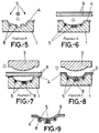
- Figures 1 to 8 show successive stages of the manufacturing process for linings object of the present invention using one press with two upper fixed molds and a single moving lower mold which may occupy positions A, B and C.
- Figure 9 shows a detailed cross section of a lining for vehicle roofs with integrated functions obtained by the process of the previous figures.
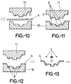
- Figures 10 to 17 show the different sequences of an alternative realisation of the process of figures 1 to 8 which results in the same lining of figure 9, but which uses two presses with identical lower fixed molds and different upper molds.
- Figures 25 to 34 show the different sequences of an alternative realisation of the process of figures 10 to 17 which results in the lining of figure 9.
- Figures 18 to 24 finally show the different sequences of another alternative realisation of the process of figures 1 to 8 which also results in the lining of figure 9 where shaping of the support and the rest of the roof is done separately in different presses, and these are later joined.
-
- In view of these figures, specifically of figures 1 to 8, one can see how the process of the invention is based on the use of a press with a single movable lower mold (1) and two upper fixed molds (2) and (3), where lower mold (1) may occupy any of three positions, one completely independent from the upper molds (position A) and another two which are opposite the latter, a position B opposite mold (2) and a position C opposite mold (3).
- The process begins at position A, as seen in figures 1 and 2, where on top of upper mold (1) is placed layered body (4), which is initially flat, and which forms the support of the different functions (5), upon which mold (1) travels to position B opposite the first upper mold (2) as shown in figure 3, molds (1) and (2) having tongue (6) and groove (7), so that after closing one mold on the other, recesses (8) are defined in support (4) for functions (5), as seen in figure 4.
- After this functions (5) are inserted in recesses (8), for which mold (1) returns to position (A), where the functions (5) can be easily inserted.
- At this time, on mold (1) and specifically on support (4) and functions (5) are set the remaining layers (9) which form part of the lining, as shown in figure 6, after which the set is moved to position (C), shown in figure 7, under second upper mold (3) which is suitably configured so that layers (9) are deformed until they match support (4), closing the mouths of the recesses (8) as shown particularly in figure 8, at which position the lining of figure 9 is obtained perfectly finished with its functions integrated in it, with its visible face facing upwards and its hidden face downwards.
- Nevertheless, it is possible to use two independent presses, as shown in figures 10 to 17, so that molds (10) and (11) of the first press are configured so that support (4) is suitably deformed, configuring in it the recesses (8) of the previous case, in which case support (4) is extracted from the first press already formed and functions (5) are to be inserted within it, as shown in figure (13), the remaining layers (9) which make up the lining being adapted to this set as well as the outer coating, not yet deformed, in order to introduce the set in a second press in which the lower mold (10'' matches mold (10) of the first press, while mold (12) is configured to suitably deform layers (9) as done by mold (3) in the previous case, with the same lining of figure 9 being obtained as a result.
- This alternative realisation can also be carried out as shown in figures 25 to 34, where a first set of layers (17) is formed by a wide layer of card or paper (16), on top of which is a layer of fiberglass (15) and finally a polyurethane layer (14) with an adhesive on its lower face.
- This set of layers (17) is inserted in the first press on lower mold (18) on which upper mold (19) acts to form in this first set of layers (17) both the required references and the housings for functions (5). Afterwards set of layers (17) is removed already shaped, to distribute functions (5) within it. Additionally, a second set of layers (20) is formed which incorporates the outer coating and it is placed on the first set of layers (17) as shown in figure (30). Both sets of layers (17) and (20) are introduced superimposed in the second press, where as mold (21) closes on lower mold (22) the roof lining is finally formed as shown in figure 34.
- The second set of layers (20) may consist of a polyurethane layer soaked in adhesive on its lower and upper faces, with a fiberglass layer on top of this polyurethane layer. As an option, the second set of layers (20) may consist of a fiberglass layer plus an adhesive layer on top.
- The tasks of placing the first set of layers (17) in the first press, distributing functions (5), placing the second set of layers (20) on top of the first one and placing both sets in the second press can be performed manually or automatically.
- Also employing two presses, and according to figures 18 to 24, first press (10-11) is identical to that of the earlier case, and deformation of support (4) is also achieved in it, while a lower mold (13) is present in the second press matching the curvature of an upper mold (12) as in the second press of the previous case. In this case the sole purpose of the second press is to deform the rest of layers (9) which shall make up the lining, as shown in figures 20 and 21, so that in this case support (4) is obtained shaped for functions (5) on one hand, and on the other remaining layers (9) also shaped are obtained; after functions (5) are inserted the two sets obtained in the presses are joined as seen in figure 24, so that the same lining shown in figure 9 is obtained.
Claims (7)
- Lining manufacturing process, particularly for vehicle roof linings with integrated functions, characterised in that in a first operational stage layered body (4) which makes up the support for the functions is coupled to a moving mold (1), so that at a second operational stage said mold (1) is moved to a position opposite a mold (2) which, when closing on the first mold, forms housings or recesses (8) in support (4), in which functions (5) are introduced immediately afterwards, with the remaining layers (9) which make up the lining placed on said lower moving mold, so that at a later operational stage lower moving mold (1) is placed opposite another upper mold (3), which upon closing on the first one causes the final formation of the remaining layers (9) and their adaptation to each other and to base support (4).
- Lining manufacturing process as in claim 1, characterised in that as an option two presses (10-11), (10'-12) are used, so that support (4) is formed in the first press (10-11) and then removed from it to receive functions (5) and the remaining lining components (9) as well as the outer coating, with this set then introduced in the second press (10'-12), where such layers or components (9) are deformed and attached to each other and to support (4).
- Lining manufacturing process as in previous claims, characterised in that as an option presses (18-19) and (21-22) are used, initially forming a set of layers (17) which is introduced in the first press (18-19) where it is shaped, to be later removed and couple functions (5) within it, and at a later stage place on top of this set of layers (17) a second set of layers (20) which incorporates the outer coating, both sets of layers (17) and (20) being introduced in the second press (21-22) where the roof lining is finally formed.
- Lining manufacturing process as in previous claims, characterised in that the first set of layers (17) consists of a card or paper layer (16) on top of which a fiberglass layer (159 is placed, and on top of this one a polyurethane layer (14) with an adhesive on its bottom face,, while the second set of layers (20) consists of a polyurethane layer with adhesive on both faces and on top of it a fiberglass layer, and as an option the second set of layers (20) can consist of a fiberglass layer with adhesive on its top face.
- Lining manufacturing process as in previous claims, characterised in that two molds (10-11), (13-12) are employed in it, with support (4) shaped in the first one and the remaining layers (9) which are part of the lining in the second one, so that in another operational stage, after removing these elements from their molds, functions (5) are coupled to shaped support (4) and the remaining layers which complete lining (9) are attached to this set.
- Lining for vehicle roofs with integrated functions, according to any of the procedures of the previous claims, which comprises a number of layers of different materials, of which one is the support for the functions, characterised in that this support layer is of a suitably deformable material, so that it allows formation of recesses or housings (8) for the various functions, maintaining its,new form stable, for which said support (4) is made from thermoplastic materials, thermostable materials or a composite material.
- Lining for vehicle roofs with integrated functions as in claim 6, characterised in that the recesses or housings (8) of support (4) which receive functions (5) are closed with the remaining layers (9) which make up the layered lining body.
Applications Claiming Priority (1)
| Application Number | Priority Date | Filing Date | Title |
|---|---|---|---|
| PCT/ES1998/000049 WO1999043517A1 (en) | 1998-02-27 | 1998-02-27 | Process for fabricating liners, and liner for a vehicle roof with integrated functions |
Publications (2)
| Publication Number | Publication Date |
|---|---|
| EP0979760A1 true EP0979760A1 (en) | 2000-02-16 |
| EP0979760B1 EP0979760B1 (en) | 2002-11-06 |
Family
ID=8302376
Family Applications (1)
| Application Number | Title | Priority Date | Filing Date |
|---|---|---|---|
| EP98904184A Expired - Lifetime EP0979760B1 (en) | 1998-02-27 | 1998-02-27 | Process for fabricating liners, and liner for a vehicle roof with integrated functions |
Country Status (5)
| Country | Link |
|---|---|
| US (1) | US6375778B1 (en) |
| EP (1) | EP0979760B1 (en) |
| AU (1) | AU6215998A (en) |
| DE (1) | DE69809219D1 (en) |
| WO (1) | WO1999043517A1 (en) |
Cited By (10)
| Publication number | Priority date | Publication date | Assignee | Title |
|---|---|---|---|---|
| WO2001094155A1 (en) * | 2000-06-08 | 2001-12-13 | Lear Corporation | Modular headliner assembly and method of making same |
| EP1147875A3 (en) * | 2000-04-19 | 2002-06-12 | Paul Kiefel Gmbh | Method for partial surface shaping of a with decorative material coated support part |
| US6464381B2 (en) | 2000-02-26 | 2002-10-15 | Federal-Mogul World Wide, Inc. | Vehicle interior lighting systems using electroluminescent panels |
| EP1249369A1 (en) * | 2001-04-11 | 2002-10-16 | Steyr-Daimler-Puch Fahrzeugtechnik AG & CO. KG | Interior trim element of a motor vehicle with electrical components |
| EP1362744A3 (en) * | 2002-05-17 | 2004-06-23 | Seeber AG & Co. KG | Building element of synthetic material, in particular for an automobile, and process for manufacturing it |
| US7143514B2 (en) * | 2000-07-10 | 2006-12-05 | Honda Giken Kogyo Kabushiki Kaisha | Method for manufacturing a vehicular body panel |
| EP2415639A1 (en) * | 2010-08-02 | 2012-02-08 | International Automotive Components Group GmbH | Trim panel device for a motor vehicle with integrated lighting system and manufacturing method |
| FR2973750A1 (en) * | 2011-04-07 | 2012-10-12 | Cera | Trim panel e.g. luggage covering shelf, for motor vehicle, has core formed in middle portion of reinforcement corner of bending plate and occupying conduit throughout its entire volume, where core is made of cellulose fiber |
| US10562446B2 (en) | 2015-03-23 | 2020-02-18 | International Automotive Components Group Gmbh | Interior trim element for a motor vehicle |
| US10759332B2 (en) | 2016-01-14 | 2020-09-01 | Weidplas Gmbh | Component comprising a flat decorative element and housing |
Families Citing this family (15)
| Publication number | Priority date | Publication date | Assignee | Title |
|---|---|---|---|---|
| US6555042B1 (en) * | 1998-07-24 | 2003-04-29 | Lear Corporation | Method of making a vehicle headliner assembly with integral speakers |
| SG108832A1 (en) * | 2001-01-24 | 2005-02-28 | Nippon Paint Co Ltd | Method of fabricating a membranous substance and method of fabricating a multilayer membranous substance |
| US7234850B2 (en) | 2001-07-24 | 2007-06-26 | Grupo Antolin-Ingenieria, S.A. | Method of producing roof panelling with an integrated lighting system and the panelling thus obtained |
| US7037455B2 (en) * | 2001-12-21 | 2006-05-02 | Mattel, Inc. | Insert molding method |
| US20030159264A1 (en) * | 2002-02-22 | 2003-08-28 | The Dow Chemical Company | Automotive roof module and method of assembly of the module to an automotive vehicle |
| US20040211582A1 (en) * | 2003-04-23 | 2004-10-28 | Siemens Vdo Automotive, Inc. | Vehicle component having an electrical conductor adhesively secured into the component |
| DE10252603A1 (en) * | 2002-11-12 | 2004-05-27 | Lear Corp., Southfield | Automobile roof liner manufacture involves application of reinforcing layers onto a core to form a sandwich structure, then pressing an energy absorption member onto the sandwich |
| US7218745B2 (en) * | 2002-12-23 | 2007-05-15 | Lear Corporation | Headliner transducer covers |
| US6685262B1 (en) | 2003-03-26 | 2004-02-03 | Lear Corporation | Foam in place integral air duct |
| US7536019B2 (en) | 2003-12-22 | 2009-05-19 | Lear Corporation | Audio system for use with a vehicle |
| DE102006014313A1 (en) * | 2006-03-28 | 2007-10-04 | Jacob Composite Gmbh | Process for producing a molded part |
| US7736568B2 (en) * | 2006-09-19 | 2010-06-15 | Mattel, Inc. | Systems and methods of incorporating preformed items into a molded article |
| US20120088089A1 (en) * | 2010-09-03 | 2012-04-12 | Cvg Management Corporation | Rigidity controlled fiberglass |
| US9221210B2 (en) * | 2012-04-11 | 2015-12-29 | Whirlpool Corporation | Method to create vacuum insulated cabinets for refrigerators |
| JP6430284B2 (en) * | 2015-02-25 | 2018-11-28 | 林テレンプ株式会社 | Silencer for automobile and manufacturing method thereof |
Family Cites Families (11)
| Publication number | Priority date | Publication date | Assignee | Title |
|---|---|---|---|---|
| JPS5942301Y2 (en) * | 1976-07-15 | 1984-12-10 | 日産自動車株式会社 | Cardboard roof trim |
| US4572856A (en) * | 1984-11-05 | 1986-02-25 | Ex-Cell-O Corporation | Composite molded article and process using self-positioning laminated stiffener |
| JPH01150512A (en) | 1987-12-09 | 1989-06-13 | Honda Motor Co Ltd | Method for molding resin foam equipped with flexible circuit member |
| EP0364102A3 (en) * | 1988-09-19 | 1990-05-02 | Bridgestone Australia Limited | Vehicle headliner |
| DE3837171C2 (en) | 1988-11-02 | 1993-11-04 | Pelz Ernst Empe Werke | FERTIGHIMMEL FOR MOTOR VEHICLES |
| JPH02158304A (en) * | 1988-12-13 | 1990-06-18 | Takehiro:Kk | Manufacture of interior base material for automobile |
| JPH02175326A (en) * | 1988-12-27 | 1990-07-06 | Nissan Motor Co Ltd | Sealing structure of car window panel |
| IT1232899B (en) * | 1989-08-04 | 1992-03-05 | Fiat Auto Spa | PANEL PARTICULARLY FOR VEHICLE DOORS AND RELATED MANUFACTURING METHOD |
| JPH04119828A (en) * | 1990-09-11 | 1992-04-21 | Toyoda Gosei Co Ltd | Preparation of foamed base material product having mounting jig |
| JP2726961B2 (en) * | 1992-01-28 | 1998-03-11 | 住友化学工業株式会社 | Multilayer molded article and molding method thereof |
| ES1027967Y (en) * | 1994-05-11 | 1995-05-16 | Irausa Ing Sa | SELF-SUPPORTING TRIM FOR INTERIOR COATING OF VEHICLE CEILINGS. |
-
1998
- 1998-02-27 DE DE69809219T patent/DE69809219D1/en not_active Expired - Lifetime
- 1998-02-27 US US09/403,845 patent/US6375778B1/en not_active Expired - Fee Related
- 1998-02-27 AU AU62159/98A patent/AU6215998A/en not_active Abandoned
- 1998-02-27 WO PCT/ES1998/000049 patent/WO1999043517A1/en not_active Ceased
- 1998-02-27 EP EP98904184A patent/EP0979760B1/en not_active Expired - Lifetime
Non-Patent Citations (1)
| Title |
|---|
| See references of WO9943517A1 * |
Cited By (13)
| Publication number | Priority date | Publication date | Assignee | Title |
|---|---|---|---|---|
| US6464381B2 (en) | 2000-02-26 | 2002-10-15 | Federal-Mogul World Wide, Inc. | Vehicle interior lighting systems using electroluminescent panels |
| USRE42340E1 (en) | 2000-02-26 | 2011-05-10 | Federal Mogul World Wide, Inc. | Vehicle interior lighting systems using electroluminescent panels |
| EP1147875A3 (en) * | 2000-04-19 | 2002-06-12 | Paul Kiefel Gmbh | Method for partial surface shaping of a with decorative material coated support part |
| WO2001094155A1 (en) * | 2000-06-08 | 2001-12-13 | Lear Corporation | Modular headliner assembly and method of making same |
| US6783624B2 (en) | 2000-06-08 | 2004-08-31 | Lear Corporation | Modular headliner assembly and method of making same |
| US7143514B2 (en) * | 2000-07-10 | 2006-12-05 | Honda Giken Kogyo Kabushiki Kaisha | Method for manufacturing a vehicular body panel |
| EP1249369A1 (en) * | 2001-04-11 | 2002-10-16 | Steyr-Daimler-Puch Fahrzeugtechnik AG & CO. KG | Interior trim element of a motor vehicle with electrical components |
| EP1362744A3 (en) * | 2002-05-17 | 2004-06-23 | Seeber AG & Co. KG | Building element of synthetic material, in particular for an automobile, and process for manufacturing it |
| EP2415639A1 (en) * | 2010-08-02 | 2012-02-08 | International Automotive Components Group GmbH | Trim panel device for a motor vehicle with integrated lighting system and manufacturing method |
| US8506141B2 (en) | 2010-08-02 | 2013-08-13 | International Automotive Components Group Gmbh | Trim means for a motor vehicle having integrated lighting system |
| FR2973750A1 (en) * | 2011-04-07 | 2012-10-12 | Cera | Trim panel e.g. luggage covering shelf, for motor vehicle, has core formed in middle portion of reinforcement corner of bending plate and occupying conduit throughout its entire volume, where core is made of cellulose fiber |
| US10562446B2 (en) | 2015-03-23 | 2020-02-18 | International Automotive Components Group Gmbh | Interior trim element for a motor vehicle |
| US10759332B2 (en) | 2016-01-14 | 2020-09-01 | Weidplas Gmbh | Component comprising a flat decorative element and housing |
Also Published As
| Publication number | Publication date |
|---|---|
| AU6215998A (en) | 1999-09-15 |
| DE69809219D1 (en) | 2002-12-12 |
| EP0979760B1 (en) | 2002-11-06 |
| WO1999043517A1 (en) | 1999-09-02 |
| US6375778B1 (en) | 2002-04-23 |
Similar Documents
| Publication | Publication Date | Title |
|---|---|---|
| EP0979760B1 (en) | Process for fabricating liners, and liner for a vehicle roof with integrated functions | |
| EP1749637B1 (en) | Automobile trim | |
| CN102427925B (en) | Housing shell for portable electrical devices and method for the production thereof | |
| CA2149180A1 (en) | Method of making a headliner and the like | |
| CN103402820B (en) | The vehicle decorative top with exquisite periphery and the method obtaining it | |
| JP2007532364A (en) | Automotive interior decoration components | |
| US7059658B2 (en) | Multi-layered inside lining piece | |
| TW200800548A (en) | Plastic skin with switching function | |
| US5678879A (en) | Sun visor for vehicles | |
| US20020153741A1 (en) | Instrument panel and method of manufacture | |
| US5487800A (en) | Method of making a covered article by vacuum drawing | |
| CZ283393A3 (en) | Process for producing a system of a door for safety air bag and dashboard | |
| JP2001191346A (en) | Manufacturing method of body parts with sandwich structure | |
| CN109177884A (en) | A kind of three-bend luggage case board putting things part of automobile and preparation method thereof | |
| US20010019200A1 (en) | Leather covering piece for a vehicle interior lining, a vehicle interior lining and a method for the production of a leather covering piece and of a vehicle interior lining | |
| EP1082871B1 (en) | Molded in speaker grid | |
| CN113459375B (en) | Method for producing a support element for a seat | |
| JPS596229B2 (en) | Manufacturing method of composite molded body | |
| CN111194261A (en) | Hybrid component manufacturing method, hybrid component manufactured therefrom and use of hybrid component | |
| CN101027207A (en) | Trim panel comprising a decorative surface | |
| US20060038320A1 (en) | Convertible boot system and method of making same | |
| JPS60222214A (en) | Preparation of trim panel for vehicle | |
| US6533880B1 (en) | Method of making a combination speaker grill and automotive interior trim panel | |
| CN118613360A (en) | Method for producing a decorative element with a functional body and a filling tool, and a decorative element | |
| CN112606521A (en) | Manufacturing method of vehicular atmosphere roof |
Legal Events
| Date | Code | Title | Description |
|---|---|---|---|
| PUAI | Public reference made under article 153(3) epc to a published international application that has entered the european phase |
Free format text: ORIGINAL CODE: 0009012 |
|
| 17P | Request for examination filed |
Effective date: 19991117 |
|
| AK | Designated contracting states |
Kind code of ref document: A1 Designated state(s): DE ES FR GB IT |
|
| GRAG | Despatch of communication of intention to grant |
Free format text: ORIGINAL CODE: EPIDOS AGRA |
|
| 17Q | First examination report despatched |
Effective date: 20020204 |
|
| GRAG | Despatch of communication of intention to grant |
Free format text: ORIGINAL CODE: EPIDOS AGRA |
|
| GRAH | Despatch of communication of intention to grant a patent |
Free format text: ORIGINAL CODE: EPIDOS IGRA |
|
| GRAH | Despatch of communication of intention to grant a patent |
Free format text: ORIGINAL CODE: EPIDOS IGRA |
|
| GRAA | (expected) grant |
Free format text: ORIGINAL CODE: 0009210 |
|
| AK | Designated contracting states |
Kind code of ref document: B1 Designated state(s): DE ES FR GB IT |
|
| PG25 | Lapsed in a contracting state [announced via postgrant information from national office to epo] |
Ref country code: IT Free format text: LAPSE BECAUSE OF FAILURE TO SUBMIT A TRANSLATION OF THE DESCRIPTION OR TO PAY THE FEE WITHIN THE PRESCRIBED TIME-LIMIT;WARNING: LAPSES OF ITALIAN PATENTS WITH EFFECTIVE DATE BEFORE 2007 MAY HAVE OCCURRED AT ANY TIME BEFORE 2007. THE CORRECT EFFECTIVE DATE MAY BE DIFFERENT FROM THE ONE RECORDED. Effective date: 20021106 Ref country code: FR Free format text: LAPSE BECAUSE OF FAILURE TO SUBMIT A TRANSLATION OF THE DESCRIPTION OR TO PAY THE FEE WITHIN THE PRESCRIBED TIME-LIMIT Effective date: 20021106 |
|
| REG | Reference to a national code |
Ref country code: GB Ref legal event code: FG4D |
|
| REF | Corresponds to: |
Ref document number: 69809219 Country of ref document: DE Date of ref document: 20021212 |
|
| PG25 | Lapsed in a contracting state [announced via postgrant information from national office to epo] |
Ref country code: DE Free format text: LAPSE BECAUSE OF FAILURE TO SUBMIT A TRANSLATION OF THE DESCRIPTION OR TO PAY THE FEE WITHIN THE PRESCRIBED TIME-LIMIT Effective date: 20030207 |
|
| PG25 | Lapsed in a contracting state [announced via postgrant information from national office to epo] |
Ref country code: GB Free format text: LAPSE BECAUSE OF NON-PAYMENT OF DUE FEES Effective date: 20030227 |
|
| PG25 | Lapsed in a contracting state [announced via postgrant information from national office to epo] |
Ref country code: ES Free format text: LAPSE BECAUSE OF FAILURE TO SUBMIT A TRANSLATION OF THE DESCRIPTION OR TO PAY THE FEE WITHIN THE PRESCRIBED TIME-LIMIT Effective date: 20030529 |
|
| EN | Fr: translation not filed | ||
| PLBE | No opposition filed within time limit |
Free format text: ORIGINAL CODE: 0009261 |
|
| STAA | Information on the status of an ep patent application or granted ep patent |
Free format text: STATUS: NO OPPOSITION FILED WITHIN TIME LIMIT |
|
| GBPC | Gb: european patent ceased through non-payment of renewal fee | ||
| 26N | No opposition filed |
Effective date: 20030807 |