EP0979120B1 - Endotracheal tube - Google Patents
Endotracheal tube Download PDFInfo
- Publication number
- EP0979120B1 EP0979120B1 EP98910446A EP98910446A EP0979120B1 EP 0979120 B1 EP0979120 B1 EP 0979120B1 EP 98910446 A EP98910446 A EP 98910446A EP 98910446 A EP98910446 A EP 98910446A EP 0979120 B1 EP0979120 B1 EP 0979120B1
- Authority
- EP
- European Patent Office
- Prior art keywords
- lip
- tube
- distal end
- wall
- opening
- Prior art date
- Legal status (The legal status is an assumption and is not a legal conclusion. Google has not performed a legal analysis and makes no representation as to the accuracy of the status listed.)
- Expired - Lifetime
Links
Images


Classifications
-
- A—HUMAN NECESSITIES
- A61—MEDICAL OR VETERINARY SCIENCE; HYGIENE
- A61M—DEVICES FOR INTRODUCING MEDIA INTO, OR ONTO, THE BODY; DEVICES FOR TRANSDUCING BODY MEDIA OR FOR TAKING MEDIA FROM THE BODY; DEVICES FOR PRODUCING OR ENDING SLEEP OR STUPOR
- A61M16/00—Devices for influencing the respiratory system of patients by gas treatment, e.g. mouth-to-mouth respiration; Tracheal tubes
- A61M16/04—Tracheal tubes
- A61M16/0402—Special features for tracheal tubes not otherwise provided for
- A61M16/0418—Special features for tracheal tubes not otherwise provided for with integrated means for changing the degree of curvature, e.g. for easy intubation
-
- A—HUMAN NECESSITIES
- A61—MEDICAL OR VETERINARY SCIENCE; HYGIENE
- A61M—DEVICES FOR INTRODUCING MEDIA INTO, OR ONTO, THE BODY; DEVICES FOR TRANSDUCING BODY MEDIA OR FOR TAKING MEDIA FROM THE BODY; DEVICES FOR PRODUCING OR ENDING SLEEP OR STUPOR
- A61M16/00—Devices for influencing the respiratory system of patients by gas treatment, e.g. mouth-to-mouth respiration; Tracheal tubes
- A61M16/04—Tracheal tubes
- A61M16/0402—Special features for tracheal tubes not otherwise provided for
- A61M16/0429—Special features for tracheal tubes not otherwise provided for with non-integrated distal obturators
-
- A—HUMAN NECESSITIES
- A61—MEDICAL OR VETERINARY SCIENCE; HYGIENE
- A61M—DEVICES FOR INTRODUCING MEDIA INTO, OR ONTO, THE BODY; DEVICES FOR TRANSDUCING BODY MEDIA OR FOR TAKING MEDIA FROM THE BODY; DEVICES FOR PRODUCING OR ENDING SLEEP OR STUPOR
- A61M16/00—Devices for influencing the respiratory system of patients by gas treatment, e.g. mouth-to-mouth respiration; Tracheal tubes
- A61M16/04—Tracheal tubes
- A61M16/0475—Tracheal tubes having openings in the tube
- A61M16/0477—Tracheal tubes having openings in the tube with incorporated means for delivering or removing fluids
- A61M16/0484—Tracheal tubes having openings in the tube with incorporated means for delivering or removing fluids at the distal end
-
- A—HUMAN NECESSITIES
- A61—MEDICAL OR VETERINARY SCIENCE; HYGIENE
- A61M—DEVICES FOR INTRODUCING MEDIA INTO, OR ONTO, THE BODY; DEVICES FOR TRANSDUCING BODY MEDIA OR FOR TAKING MEDIA FROM THE BODY; DEVICES FOR PRODUCING OR ENDING SLEEP OR STUPOR
- A61M16/00—Devices for influencing the respiratory system of patients by gas treatment, e.g. mouth-to-mouth respiration; Tracheal tubes
- A61M16/04—Tracheal tubes
- A61M16/0488—Mouthpieces; Means for guiding, securing or introducing the tubes
-
- A—HUMAN NECESSITIES
- A61—MEDICAL OR VETERINARY SCIENCE; HYGIENE
- A61M—DEVICES FOR INTRODUCING MEDIA INTO, OR ONTO, THE BODY; DEVICES FOR TRANSDUCING BODY MEDIA OR FOR TAKING MEDIA FROM THE BODY; DEVICES FOR PRODUCING OR ENDING SLEEP OR STUPOR
- A61M16/00—Devices for influencing the respiratory system of patients by gas treatment, e.g. mouth-to-mouth respiration; Tracheal tubes
- A61M16/04—Tracheal tubes
- A61M16/0434—Cuffs
- A61M16/0443—Special cuff-wall materials
Definitions
- the present invention relates to endotracheal tubes for ventilation of the lungs, and more particularly, to such tubes suitable for blind guided intubation.
- the endotracheal tube is usually a preformed, semi-flexible tubular member having a gas flow lumen extending therethrough.
- the tube has an arcuate shape imparted to it and the distal tip is usually cut completely across at an angle to define a beveled edge to facilitate its insertion between the vocal cords.
- the usual method of orotracheal intubation relies on a blade laryngoscope by which to visualize the laryngeal opening so as to facilitate insertion of the tube.
- the endotracheal tube used to intubate with the blade laryngoscope is usually introduced into the laryngeal opening from the right side thereof (i.e., the patient's right side).
- the distal tip is beveled on its side relative to the curvature of the tube (i.e., the tube is cut with a left side-facing bevel that extends at an angle down from the left aspect of the tube through the right aspect) such that the terminal tip defines a right-sided chisel point, which obstructs the view of the vocal cords as little as possible as it approaches those cords and provides a suitably narrow contour for insertion therebetween, and a left-sided elliptical hole circumscribed by the left side-facing beveled edge.
- Intubation with the blade laryngoscope presents significant difficulties and risks, however.
- blind orotracheal intubation Another approach to intubation is so-called blind orotracheal intubation in which a guide device is inserted into the throat to guide the orotracheal tube into the laryngeal opening without requiring visualization of the laryngeal opening.
- Blind intubation guides have been developed which both minimize injury and trauma in use, and also substantially reduce the risk of misintubation. Such intubation guides are shown, for example, in U. S. Patent No. 5,339,805 and U.S. Patent 5 743 254.
- the endotracheal tube is advanced through the guide into the laryngeal opening along the midline of that opening rather than obliquely from the side of that opening, as with a blade laryngoscope.
- the side-facing bevel of the tube tip may be of no useful benefit and, indeed, may be disadvantageous in that the right-sided chisel point may become impacted on the right side of the larynx, and the left-facing elliptical hole may snag on left-sided laryngeal features, such as the left arytenoid and corniculate cartilages, thus preventing the tube from advancing into the trachea.
- a visual means to facilitate intubation is to insert the imaging bundle of a flexible fiberoptic bronchoscope into the lumen of an orotracheal tube, so that the imaging lens of the scope is positioned just inside the distal opening of the tube. This allows the bronchoscopist to see whatever is immediately in front of the tip of the tube.
- the tube, containing this imaging means is then inserted into the throat with a blind intubation guide such as the devices in the aforesaid '805 patent and '737 patent application referenced above.
- the intubation guide conducts the tip to a position directly above the larynx, so that the bronchoscopist can immediately see the vocal cords and advance the scope-containing tube tip there-through into the trachea.
- Such a strut also prevents another blind intubation technique in which the tube is railroaded over another member such as a tubular orotracheal introducer.
- the introducer is inserted into an orotracheal tube and extends through the tube lumen beyond the distal tip.
- the forward end of the introducer is inserted through the laryngeal opening into the trachea, and the tube is railroaded down over the introducer into the trachea.
- the introducer must remain aligned with the lumen of the tube which is intended to be railroaded over the introducer.
- the transverse strut deflects the introducer out a side opening thereby preventing the necessary alignment.
- Railroading the tube over a misaligned introducer will cause the tube to snag on the larynx, resulting in trauma to the larynx and failed intubation.
- nasotracheal intubation Another blind intubation technique is nasotracheal intubation in which an endotracheal tube is passed through the nose into the back of the throat and then down into the larynx and trachea (in which case the tube may be referred to as a nasotracheal tube).
- the nose contains friable mucosa which is especially susceptible to mechanical trauma.
- Standard, side-beveled tubes due to the rigidity of their tips, can disrupt this mucosa and provoke substantial nasal bleeding when they are advanced through the nose. Such rigidity also prevents them from gently turning the sharp comer at the back of the nose in order to travel downward toward the larynx. Additional trauma and bleeding can be caused at that site.
- tubes used for orotracheal and nasotracheal intubation are unlubricated and can therefore cause frictional trauma to anatomical structures during insertion into the body. Intubationists who wish to avoid such friction must pause to manually lubricate the tube before inserting it into the body.
- the lubricant is not always applied uniformly, and may also be easily rubbed off, as when the tube is advanced through a narrow nostril. As a consequence, manual lubrication does not assure that frictional trauma will be avoided.
- An endotracheal tube proposed in U.S. Patent No. 4,050,466 has a rear-facing bevel (i.e., the tube tip is cut at an angle that extends down from the outer surface of the tube's convex posterior wall through the outer surface of the tube's concave anterior wall), rather than a side-facing bevel.
- the rear-facing bevel moves the chisel point of the bevel tip from a lateral aspect of the tube to the anterior aspect.
- the chisel point created by this complete posterior bevel is, however, too broad, and too anteriorly disposed.
- the tube may have a tendency to become impacted on the posterior base of the epiglottis or hung up on the vocal cords at the anterior commissure of the glottis where the space between the vocal cords is the narrowest. Even if the tube successfully passes through the glottis, the chisel point would tend to become lodged on or between the cartilaginous rings within the trachea thus preventing further advancement in the trachea.
- the tip of the tube is rigid and can, therefore, do substantial damage to structures in the nose and throat when the usual force is applied to advance the tube.
- the present invention in one aspect provides an endotracheal tube comprising a tubular member extending between a proximal end and a distal end and having a single opening across the distal end, the tubular member having a generally predefined curvature with a first wall aspect and a second, oppositely disposed wall aspect along its length define an airway lumen therebetween for flow of gas between the proximal end and the opening, characterised in that the opening is effectively unobstructed and has a lip projecting from the second wall aspect at the distal end beyond the opening and curving inwardly toward the first wall aspect.
- the present invention in another aspect provides an endotracheal tube comprising a tubular member extending between a proximal end and a distal end and having a single opening across the distal end, the tubular member defining an airway lumen therethrough for flow of gas between the proximal end and the opening at the distal end, the tubular member having a generally pre-defined curvature so as to define a first wall aspect and a second, oppositely disposed wall aspect of the distal end, characterised by the distal end having an incomplete bevel extending across the opening from the first wall aspect toward, but not completely through, the second wall aspect of the tubular member, and a lip projecting from the distal end beyond the opening and curving inwardly toward the first wall aspect.
- the invention also provides corresponding methods.
- the present invention provides an improved endotracheal tube for orotracheal and nasotracheal intubation, which minimizes the tendency of such tubes to snag, drag, and traumatize anatomical features within the nose, larynx, and/or trachea.
- the improved endotracheal tube is especially useful in facilitating intubation with blind intubation guides, fiberoptic bronchoscopes, and other orotracheal tube introducers.
- the distal tip of the endotracheal tube is provided with only a partial or incomplete posterior or rear-facing bevel which allows the tube to slide down the midline of the rear wall of the larynx without snagging the arytenoid cartilages, which are lateral thereto.
- the partial posterior bevel leaves a depending projection or lip of the anterior tube wall rather than a chisel point.
- the partial posterior bevel does not cut completely through the anterior wall of the tube, but instead stops short thereof such as at the inner surface of the anterior wall.
- the partial bevel may advantageously extend partially into the inner surface of the anterior wall such that the lip has a wall thickness that is thinner than the adjacent anterior wall of the tube.
- the depending lip thus created is advantageously tapered to facilitate its insertion through a narrow nasal passageway and/or into the narrow opening (glottis) between the vocal cords.
- the lip is also curved posteriorly back toward the axis of the tube lumen to define a convex bearing surface which will slide easily along a nasal passageway as well as down the inner surface of the epiglottis and the inner surface of the anterior tracheal wall without becoming impacted on the epiglottis, anterior commissure, or tracheal rings.
- the downwardly extending convex bearing surface of the lip may be aligned with the outer anterior tube wall or offset therefrom, and may include a fin on its inferior aspect to facilitate insertion into the glottis.
- the lip is semi-flexible and confined to a short length which curves to about, but generally not further than, the midline axis of the tube's distal opening so that if the lip impacts in the body and flexes upward, it will not occlude the lumen of the tube or obstruct the flow of air to the patient's lungs.
- the thinner wall of the lip relative to the wall of the remainder of the tube enhances the lip's vertical flexibility.
- the lip will not block the passage of a suction catheter or obstruct the view of a bronchoscope fiberbundle passed through the tube to its tip or beyond.
- the lip itself will be flexed backward by such tubular instruments when they contact the lip, and will return to its original shape when they are withdrawn from contact with the lip.
- the lip is tapered to a narrowly rounded distal edge and a biocompatible lubricious coating may advantageously be covalently bonded to the forward 25% of the tube, including the inflation cuff.
- the surface lubricity of the tube thus achieved is uniform and is not readily wiped off through inadvertence or otherwise, such as by sliding the tube through a narrow nostril.
- the angle of the curved lip may be about 25° to 35° measured from a line tangent to the lip relative to the midline axis, and is advantageously at an angle of about 30°.
- the lip includes a portion offset outwardly of the tube and then curves back toward the midline axis, the lip curves at an angle of about 30° to 40°.
- one or two holes known as "Murphy eyes" may be provided, for example, through opposed sides of the tube wall adjacent the distal tip above and lateral to the posterior bevel.
- an endotracheal tube which can be passed through the nose or mouth into the larynx and trachea with minimum trauma, minimum friction, and without becoming impacted or snagged on anatomical features of and within the nose, larynx, or trachea, such as the cartilages in the nose and rear wall of the larynx, the vocal cords, vocal folds, epiglottis, and anterior tracheal rings.
- the same endotracheal tube thus provided can be used with a conventional blade laryngoscope and can also cooperate with a blind intubation guide and with a fiberoptic bronchoscope inserted through the tube to the distal tip thereof or beyond to achieve an unobstructed view of the anatomy directly in front of the tube and to achieve fiberoptic (visually directed) intubation.
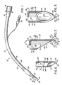
- Tube 10 is defined by an elongated plastic tubular member 12 (such as of polyvinyl chloride or plasticized polyvinyl chloride) having a proximal end 14 to which is removably attached a connector piece 16, and a distal tip end 18.
- the wall 20 of member 12 defines therein a gas flow lumen 22 opening into the proximal end 14 and distal end 18 for flow of gas, such as oxygen, to ventilate a patient.
- An inflatable cuff or balloon 24 is provided adjacent distal end 18 and coupled to an inflation port 26 as is typical for standard, adult endotracheal tubes. For smaller size tubes, cuff 24 and port 26 may be eliminated.
- Tubular member 12 has a generally arcuate shape as seen in Fig. 1. With specific reference to distal tip 18, tube 12 has a posterior wall aspect 30 with outer surface 32 and inner surface 34, an anterior wall aspect 36 with outer surface 38 and inner surface 40, and lateral wall aspects 42 each with an outer surface 44 and an inner surface 46 extending between posterior and anterior wall aspects 30 and 36. The inner surfaces 34, 40, and 46 cooperate to define gas flow lumen 22.
- tip end 18 is provided with a partial or incomplete posterior (i.e., rear-facing) bevel 50 extending at an angle ⁇ of about 37° (measured relative to the midline axis 52 of distal tube end 18) from posterior outer surface 32 toward anterior wall aspect 36, but not completely through wall aspect 36 so as to leave a depending projection or lip 54 of anterior tube wall material 36.
- Bevel 50 may terminate at inner anterior wall surface 40 as at 55 as seen in Fig. 2 such that the wall thickness of lip 54 is about equal to the thickness of anterior wall aspect 36.
- bevel 50 may continue past surface 40 such that wall thickness of resulting lip 54 is thinner (i.e., between inner surface 104 and bearing surface 60) than anterior wall 36 (i.e., between inner surface 40 and outer surface 38). Where the thinner lip 54 is utilized, lip 54 is advantageously 20% to 25% thinner than anterior wall 36.
- Posterior bevel 50 defines an elliptically-shaped, single distal opening 56 (Fig. 3), the major diameter of which intersects midline axis 52 and lip 54.
- Lip 54 is sized such that its extent from end 55 of bevel 50 to lip free edge 58 is not greater than the distance D between the axis 52 and the inner anterior wall surface 40 so as not to extend past midline axis 52 and not to occlude opening 56 should lip 54 be flexed upward toward that opening.
- a curvature is advantageously imparted to lip 54 such that lip 54 curves back along a line intersecting the major diameter of opening 56 toward axis 52.
- Lip 54 projects at an angle ⁇ measured between a line tangent to the midpoint of inferior or outer surface 60 of lip 54 and midline axis 52 of between about 25° and 35°, and advantageously about 30°.
- Lip 54 has lateral side edges 62 that taper and converge smoothly into free edge 58 which is provided with a rounded bottom 64.
- a fin 66 (shown in dotted line in Figs. 2 and 3) may be included on outer surface 60 running along the midline axis of lip 54. Fin 66 constitutes a tapered extension of surface 60 and progressively narrows from its origin 67 (confronting bevel end 55) to its free end 68 adjacent lip free edge 58.
- Lip 54 is semi-flexible so as to yield and flex on impact.
- lip 54 may be flexed backward away from bevel 50 by instruments (not shown) passed through tube 10 and beyond bevel 50, but will return to its original position when such instruments are withdrawn from contact with lip 54.
- instruments not shown
- opening 56 is, effectively, unobstructed.
- Lip 54 and cuff 24 and the portion of tube 12 therebetween, constituting about the forward 25% of tube 10, are advantageously provided with a biocompatible lubricious coating covalently bonded to their surfaces, such as that supplied by SurModics, Inc. of Eden Prairie, Minnesota based on technology disclosed in U.S. Patent No. 5,637,460 and related patents.
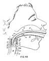
- the lubricious coating reduces the friction between tube 12 and anatomical structures through which it passes, such as vocal cords 88 and trachea 86 (Fig. 4A); between tube 12 and devices through which it passes, such as blind intubation guide 73 (Fig. 4A); and between tube 12 and medical instruments which pass through it, such as introducer 100 (Fig. 5A).
- tube 10 Immediately prior to use of tube 10, the lubricious coating is activated by wetting it with a dip or spray of water or saline.
- An alternative form of tube lubrication immediately prior to use thereof is to manually apply a film of water-soluble, biocompatible lubricant, such as SURGILUBE, available from Altana, Inc. in Melville, New York.
- the guide wall 74 thus defines a bearing surface along which an endotracheal tube may be directed into the laryngeal opening 70.
- the posterior bevel 50 may be seen as facing, and thus sliding along, guide wall 74 as tube 10 passes towards laryngeal opening 70 as shown schematically in Fig. 4A (note that cuff 24 has been eliminated for sake of simplicity).
- the curvature of lip 54 causes outer surface 60 and/or fin 66 thereof to serve as a bearing surface to slide along aspects of the guide device that pass over the tongue 80 and epiglottis 82.
- the central position of lip 54 further serves to facilitate the trajectory of tip end 18 into and through laryngeal opening 70.
- posterior bevel 50 helps to slide tube tip 18 over the posterior edge 76 of opening 70
- curved lip 54 and/or fin 66 serve to avoid snagging of tube tip 18 on the rear surface 84 of epiglottis 82, the vocal cords (as represented by glottis 88), and/or the cartilaginous rings 90 within trachea 86 (only three shown).
- the curvature of outer surface 60 of lip 54 and/or fin 66 provides a bearing surface that deflects the tube tip 18 in a sliding manner off from and/or along those anatomical processes such that tube tip 18 may be fully inserted into trachea 86 without snagging along the way. More specifically, the curvature of lip 54 helps orient the free edge 58 such that it is aligned with the midline of the posterior commissure of the glottis 88 (where the space between the vocal cords is greatest), and is aimed away from the anterior commissure of the glottis 88 (where the space between the vocal cords is narrowest).
- tube tip 18 does become snagged on any structure, such as laryngeal cartilages 76, the thinness and curvature of lip 54 predispose lip 54 to flex vertically (toward posterior tube wall 30) as tube 120 is advanced.
- Such flexion causes free edge 58 to be deflected inward toward the tube lumen 22 and away from engagement with the anatomical site where it was snagged.
- curved bearing surface 60 is rotated into contact with the anatomy immediately adjacent the snag site and, assisted by the lubricious coating on surface 60 and forward pressure on tube 10, surface 60 tends to slide away from the snag site toward an area of less resistance at which tube tip 18 is generally directed, such as glottic opening 88.
- the fin 66 is useful to help wedge apart a narrow glottic opening.
- Tube 10 is pushed against guide wall 74 such that tube tip 18 passes into and beyond laryngeal opening 70.
- the tube continues to be pushed therealong until seated within trachea 86 as desired. Thereafter, guide wall 74 may be removed from throat 72 while leaving tube 10 in place.
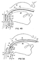
- the partial bevel 50 and lip 54 of tube 10 also facilitate intubation with an orotracheal introducer (such as a tubular fiberbundle 100 of a laryngoscope) as will now be described with reference to Figs. 5A, 5B, and 5C.
- introducer 100 is inserted into tube 10 from proximal end 14 thereof such that a distal portion 102 of introducer 100 projects out beyond distal tube end 18.
- Distal end 102 of introducer 100 is inserted into the trachea 86 and tube 10 is then railroaded over introducer 100.
- lip 54 causes the free edge 58 thereof to be turned away from epiglottis 82 as tube tip 18 passes thereover to avoid snagging on epiglottis 82 and to facilitate sliding of bearing surface 60 and tube surface 38 down the rear surface 84 of epiglottis 82.
- bevel 50 will pass against posterior edge 78 of laryngeal opening 70 at which time rear-facing bevel 50 helps tube tip 18 pass thereover and into laryngeal opening 70 without snagging on edge 76.
- the curved lip 54 meanwhile, provides a bearing surface 60 to help slide between the vocal cords at glottis 88 without snagging, as exemplified schematically in Fig.
- Tube 10 is seated down in the trachea 86 by further railroading along introducer 100 such that bearing surface 60 of curved lip 54 will slide along cartilaginous rings 90 as tube tip 18 passes into the trachea (Fig. 5C). Thereafter, introducer 100 may be removed by pulling it out from the proximal end 14 of tube 12.
- Tube 10 can also cooperate with intubation guide 73 and bronchoscope 134 to achieve inspection of larynx 70 and/or visually directed intubation of trachea 86 as will now be described with reference to Fig. 8.
- Tube 10 is wetted with water or saline if it is desired to activate the lubricious coating on the surfaces of tube 10.
- Fiberbundle 130 of bronchoscope 134 is inserted into proximal end 14 of tube 10 and advanced until objective lens 132 of fiberbundle 130 is situated adjacent lip 54 of tube tip 18. Tube 10 is then situated in intubation guide 73 which is seated adjacent larynx 70.
- tube 10 and fiberbundle 130 may then, optionally, be advanced together through guide 73 and glottis 88 into trachea 86 to achieve tracheal intubation. Thereafter, fiberbundle 130 may be removed from tube 10 by pulling it out from proximal end 14 of tube 10.
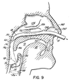
- Tube 10 is also useful for blind nasotracheal intubation, as will now be described with reference to Fig. 9.
- tube 10 is wetted to activate the lubricious coating.
- Distal end 18 of tube 10 is inserted into nostril 150 of nose 148 and advanced toward posterior pharyngeal wall 146, preferably along inferior meatus 158, between inferior concha 152 and hard palate 140.
- An alternate pathway could be along middle meatus 156, between inferior concha 152 and middle concha 154.
- Lip 54 of tube tip 18 passes over soft palate 142 and contacts wall 146.
- Tube 10 Guidance of tube 10 toward this objective is facilitated by the operator (not shown) listening at the proximal end 14 of tube 10 for breath sounds transmitted from distal end 18, so that the operator will know if tube end 18 is approaching larynx 70 and trachea 86 and should be advanced, or is deviating therefrom and should be slightly withdrawn and redirected.
- distal end 18 may be modified by inclusion of a hole or Murphy eye 120 formed completely through a lateral wall aspect 42 so as to be situated just above and lateral to posterior bevel 50, and below cuff 24.
- a pair of Murphy eyes may be positioned in confronting relationship such that the lateral disposition thereof provides alternate pathways for gas flow to the right and left mainstream bronchi (not shown) in case the opening 56 becomes occluded.
- a further alternative embodiment is shown of the distal end 18 of tube 10 in which lip 54' thereof is modified from lip 54 of the prior embodiments in that lip 54' includes a portion 200 that is offset outwardly of midline axis 52 and protrudes beyond the cylinder of outer surface 38 of anterior wall aspect 36. Lip 54' then curves back toward midline axis 52 and posterior wall aspect 30. Due to offset portion 200, however, the extent of curvature of lip 54' is such that tip 64 thereof is substantially aligned with inner surface 40 of wall aspect 36 and so does not protrude into the pathway of lumen 22. Lip 54' projects at an angle ⁇ measured between a line tangent to the midpoint of inferior or outer surface 60 of lip 54' and midline axis 52 of between about 30° and 40°.
- an endotracheal tube 10 of appropriate size for the recipient individual is selected and the lubricious coating is activated or applied.
- Lubricated tube 10 (with or without Murphy eyes 120 and/or fin 66 as desired) is inserted into the trachea 86 by use of a blind intubation guide device having a guide wall 74 as described in the aforesaid '805 patent and/or '254 patent, after which the guide device is removed.
- lubricated tube 10 is inserted into nostril 150 and advanced against meatus 158 and downward along wall 146 into larynx 70 and trachea 86.
- an introducer 100 or bronchoscope fiberbundle 130 is inserted through lubricated tube 10 to its tip or beyond and positioned above larynx 70 or into trachea 86, as desired. Tube 10 is then advanced with or railroaded downward thereover and into the trachea 86. Introducer 100 or fiberbundle 130 may then be withdrawn through tube proximal end 14. In all of these cases, the incomplete rear-facing bevel 50 and the depending lip 54 allow the tube 10 to be readily inserted into and advanced in the nose 148, throat 72 and trachea 86 without snagging on or frictionally traumatizing anatomical features of and within the nose, larynx, and trachea.
- an endotracheal tube that facilitates blind nasotracheal intubation and blind or visual orotracheal intubation without snagging on or frictionally traumatizing anatomical features of and within the nose, larynx, and trachea.
- lip 54 or 54' may be provided without a bevel 50 to tube end 18.
- lip 54 or 54' may not include fin 66.
- a barium sulfate strip (not shown) may be included in wall 20 for x-ray visualization.
- the invention in its broader aspects is, therefore, not limited to the specific details, representative apparatus and method, and illustrative examples shown and described.
Description
Claims (22)
- An endotracheal tube (10) comprising a tubular member (12) extending between a proximal end (14) and a distal end (18) and having a single opening (56) across the distal end (18), the tubular member (12) having a generally predefined curvature with a first wall aspect (30) and a second. oppositely disposed wall aspect (36) along its length defining an airway lumen (22) therebetween for flow of gas between the proximal end (14) and the opening (56), characterised in that the opening (56) is effectively unobstructed and has a lip (54) projecting from the second wall aspect (36) at the distal end (18) beyond the opening (56) and curving inwardly toward the first wall aspect (30).
- An endotracheal tube (10) comprising a tubular member (12) extending between a proximal end (14) and a distal end (18) and having a single opening (56) across the distal end (18), the tubular member (12) defining an airway lumen (22) therethrough for flow of gas between the proximal end (14) and the opening (56) at the distal end (18), the tubular member (12) having a generally pre-defined curvature so as to define a first wall aspect (30) and a second, oppositely disposed wall aspect (36) of the distal end (18), characterised by the distal end (18) having an incomplete bevel (50) extending across the opening (56) from the first wall aspect (30) toward, but not completely through, the second wall aspect (36) of the tubular member (12), and a lip (54) projecting from the distal end (18) beyond the opening (56) and curving inwardly toward the first wall aspect (30).
- An endotracheal tube as claimed in any preceding Claim wherein the distal end (18) has a longitudinal midline axis (52), the lip (54) curving inwardly toward the midline axis (52).
- An endotracheal tube as claimed in any preceding Claim wherein the lip (54) tapers to a free edge (58).
- An endotracheal tube as claimed in any preceding Claim, the distal end (18) having a longitudinal midline axis (52) spaced a distance D from an inner surface (40) of the tubular member (12), the lip (54) extending to a free edge (58) a distance not more than D whereby not to occlude the opening (56) at the distal end (18).
- An endotracheal tube as claimed in any preceding Claim wherein the lip (54) has an outer surface (60), the tube further comprising a fin (66) extending along the lip outer surface (60).
- An endotracheal tube as claimed in any preceding Claim, the lip (54) including a portion (200) being offset outwardly of an outside surface (38) of the tubular member (12).
- An endotracheal tube as claimed in any preceding Claim further comprising a Murphy eye (120) extending through the tubular member (12) and positioned just above and lateral to the opening (56).
- An endotracheal tube as claimed in any preceding Claim the lip (54) being thinner than an anterior wall (36) of the tubular member (12) at the distal end (18).
- An endotracheal tube as claimed in any preceding Claim further comprising a lubricious coating covalently bonded to at least the lip (54).
- An endotracheal tube as claimed in any preceding Claim further comprising an inflation cuff (24) associated with the tubular member (12).
- An endotracheal tube as claimed in Claim 11 further comprising a lubricious coating covalently bonded to the inflation cuff (24).
- An endotracheal tube as claimed in any preceding Claim, the lip (54) being semi-flexible.
- An endotracheal tube as claimed in any preceding Claim wherein the first wall aspect (30) defines a posterior aspect of the tubular member (12) and the second wall aspect (36) defines an anterior aspect of the tubular member (12).
- A method of forming an endotracheal tube (10) having a proximal end (14) and a distal end (18) with a single opening (56) thereat, the method comprising providing an effectively unobstructed opening (56) and being characterised by giving the tube (10) a generally predefined curvature with a first wall aspect (30) and a second, oppositely disposed wall aspect (36) along its length, defining a lip (54) projecting from the second wall aspect (36) at the distal end (18) beyond the opening (56), and curving the lip (54) inwardly toward the first wall aspect (30).
- A method of forming an endotracheal tube (10) having a proximal end (14) and a distal end (18) with a single opening (56) thereat, and a generally arcuate shape of the tube defining first (30) and second, opposite (36) wall aspects thereof at the distal end (18), the method comprising forming a bevel (50) across the opening (56) at the distal end (18), characterised in that the bevel (50) is incomplete and extends from the first wall aspect (30) to, but not completely through, the second wall aspect (36), by defining a lip (54) projecting from the second wall aspect (36) beyond the incomplete bevel (50), and by curving the lip (54) inwardly toward the first wall aspect (30).
- A method as claimed either in Claim 15 or Claim 16 wherein the distal end (18) has a longitudinal midline axis (52), the method further comprising curving the lip (54) toward the midline axis (52).
- A method as claimed in any of Claims 15 through 17 further comprising offsetting a portion (200) of the lip (54) outwardly of an outside surface (38) of the tube (10).
- A method as claimed in any of Claims 15 through 18 further comprising tapering the lip (54) to a free edge (58).
- A method as claimed in any of Claims 15 through 19 further comprising defining a fin (66) on the lip (54).
- A method as claimed in any of Claims 15 through 20 further comprising forming a Murphy eye (120) through the tube (10) just above the opening (56).
- A method as claimed in any of Claims 15 though 20 further comprising forming the lip (54) thinner than an anterior wall (36) of tubular member (12) at distal end (18).
Applications Claiming Priority (3)
| Application Number | Priority Date | Filing Date | Title |
|---|---|---|---|
| US819783 | 1997-03-18 | ||
| US08/819,783 US5873362A (en) | 1997-03-18 | 1997-03-18 | Endotracheal tube |
| PCT/US1998/005173 WO1998041273A1 (en) | 1997-03-18 | 1998-03-17 | Endotracheal tube |
Publications (2)
| Publication Number | Publication Date |
|---|---|
| EP0979120A1 EP0979120A1 (en) | 2000-02-16 |
| EP0979120B1 true EP0979120B1 (en) | 2005-05-04 |
Family
ID=25229054
Family Applications (1)
| Application Number | Title | Priority Date | Filing Date |
|---|---|---|---|
| EP98910446A Expired - Lifetime EP0979120B1 (en) | 1997-03-18 | 1998-03-17 | Endotracheal tube |
Country Status (14)
| Country | Link |
|---|---|
| US (1) | US5873362A (en) |
| EP (1) | EP0979120B1 (en) |
| JP (1) | JP3960628B2 (en) |
| CN (1) | CN1130236C (en) |
| AU (1) | AU723385B2 (en) |
| BR (1) | BR9808357A (en) |
| CA (1) | CA2281097C (en) |
| DE (1) | DE69830051T2 (en) |
| HK (1) | HK1026645A1 (en) |
| IL (1) | IL131452A (en) |
| MX (1) | MXPA99008567A (en) |
| NO (1) | NO319417B1 (en) |
| NZ (1) | NZ337421A (en) |
| WO (1) | WO1998041273A1 (en) |
Cited By (1)
| Publication number | Priority date | Publication date | Assignee | Title |
|---|---|---|---|---|
| WO2006130992A1 (en) * | 2005-06-10 | 2006-12-14 | Universite Laval | Right double lumen endobronchial tube |
Families Citing this family (32)
| Publication number | Priority date | Publication date | Assignee | Title |
|---|---|---|---|---|
| US6186987B1 (en) * | 1997-09-30 | 2001-02-13 | Ronald K. Grooters | Aortic cannula with spoon-shaped lip |
| GB9725390D0 (en) * | 1997-12-02 | 1998-01-28 | Smiths Industries Plc | Catheter assemblies and inner cannulae |
| EP1061984B2 (en) * | 1998-03-09 | 2010-03-03 | Kimberly-Clark Worldwide, Inc. | Tracheal breathing apparatus |
| US6196224B1 (en) * | 1998-09-30 | 2001-03-06 | David D. Alfery | Perilaryngeal oral airway |
| US6386199B1 (en) * | 1999-09-29 | 2002-05-14 | David D. Alfery | Perilaryngeal oral airway |
| WO2001034221A2 (en) * | 1999-11-05 | 2001-05-17 | Jonathan Gareth Weston Evans | Bite-resistant endotracheal tube |
| US6378523B1 (en) | 2000-03-15 | 2002-04-30 | Evergreen Medical Incorporated | Endotracheal tube having a beveled tip and orientation indicator |
| US6443156B1 (en) | 2000-08-02 | 2002-09-03 | Laura E. Niklason | Separable double lumen endotracheal tube |
| US6672305B2 (en) * | 2001-02-26 | 2004-01-06 | Parker Medical Limited Partnership | Shallow throat orotracheal intubation guide |
| US7552729B2 (en) * | 2001-03-05 | 2009-06-30 | The United States Of America As Represented By The Secretary Of The Army | Intubation device and method |
| DE10118605C1 (en) * | 2001-04-12 | 2002-06-13 | Ruesch Willy Gmbh | Breathing tube, for selective endotracheal/esophagus-blocked breathing, where the axial opening of a first lumen is located directly after a second inflatable balloon, so in the vicinity the first balloon, the tube has a single lumen |
| US6877512B2 (en) | 2001-09-05 | 2005-04-12 | The Regents Of The University Of California | Airway device |
| US6668832B2 (en) | 2001-12-28 | 2003-12-30 | The Regents Of The University Of California | Endotracheal tube |
| US6923176B2 (en) * | 2002-03-26 | 2005-08-02 | Willy Rusch Gmbh | Resuscitation tube |
| US7040312B2 (en) * | 2002-05-16 | 2006-05-09 | Engineered Medical Systems, Inc. | Perilaryngeal oral airway with flexible tip guide |
| US6978784B2 (en) * | 2003-12-11 | 2005-12-27 | The Research Foundation State University Of New York | Atraumatic endotracheal tube introducer and atraumatic intubation methods |
| JP2005218644A (en) * | 2004-02-05 | 2005-08-18 | Chinontec Kk | Endotracheal intubation apparatus |
| US7174889B2 (en) * | 2004-06-02 | 2007-02-13 | Board of Regents of the University of Nebraska by and on behalf of the University of Nebraska Medical Center | Device for insertion of endotracheal tube |
| US7404329B2 (en) * | 2004-12-08 | 2008-07-29 | Engineered Medical Systems, Inc. | Pressure gauge for use with an airway lumen |
| US8961532B2 (en) * | 2006-01-06 | 2015-02-24 | Bayer Essure Inc. | Atraumatic catheter tip |
| DE102006057809A1 (en) * | 2006-12-06 | 2008-06-12 | Ruprecht-Karls-Universität Heidelberg | intubation tube |
| US8104475B2 (en) * | 2008-11-05 | 2012-01-31 | Smiths Group Plc | Medical tube assemblies |
| USD666712S1 (en) * | 2008-11-12 | 2012-09-04 | William Andrew Laurence | Single use suction catheter with color-keyed suction depth indicators |
| US20110297160A1 (en) * | 2010-06-08 | 2011-12-08 | Richard Farah | Pivotable endotracheal tube assemblies |
| US20140196724A1 (en) * | 2013-01-15 | 2014-07-17 | Covidien Lp | Tracheal dilation apparatus and method of manufacture |
| CN104043174B (en) * | 2014-07-07 | 2016-06-08 | 赵泽宇 | A kind of longthening belt expands holds anti-crimping type trachea cannula |
| GB201511113D0 (en) * | 2015-06-24 | 2015-08-05 | Smiths Medical Int Ltd | Tube introducers, assemblies and methods |
| WO2018013795A1 (en) * | 2016-07-14 | 2018-01-18 | University Of Virginia Patent Foundation | Multiple beak endotracheal device and related methods thereof |
| US10258755B2 (en) * | 2017-06-11 | 2019-04-16 | Jeffrey Lee Dexter | Transitional airway |
| USD848609S1 (en) * | 2017-11-21 | 2019-05-14 | Board Of Regents, The University Of Texas System | Endotracheal tube |
| CN110064111A (en) * | 2018-01-23 | 2019-07-30 | 邹弘 | Visual bronchial cannula and its application |
| KR102329822B1 (en) * | 2020-02-19 | 2021-11-22 | 서영대학교산학협력단 | The endotracheal intubation tubes containing the shape memory means |
Family Cites Families (14)
| Publication number | Priority date | Publication date | Assignee | Title |
|---|---|---|---|---|
| US2458305A (en) * | 1947-04-26 | 1949-01-04 | Richard D Sanders | Tubular article comprising rubberlike material |
| US2862498A (en) * | 1957-06-14 | 1958-12-02 | Don J Weekes | Endotracheal tube |
| US3862635A (en) * | 1973-04-23 | 1975-01-28 | American Hospital Supply Corp | Smooth tipped endotracheal tube |
| US3964488A (en) * | 1974-11-13 | 1976-06-22 | Wallace H. Ring | Tracheal tube |
| US4050466A (en) * | 1975-10-08 | 1977-09-27 | Koerbacher Kathleen C | Endotracheal tube |
| US4231365A (en) * | 1978-01-30 | 1980-11-04 | Scarberry Eugene N | Emergency resuscitation apparatus |
| US4423725A (en) * | 1982-03-31 | 1984-01-03 | Baran Ostap E | Multiple surgical cuff |
| US5044369A (en) * | 1989-01-23 | 1991-09-03 | Harvinder Sahota | Bent topless catheters |
| US5174283A (en) * | 1989-11-08 | 1992-12-29 | Parker Jeffrey D | Blind orolaryngeal and oroesophageal guiding and aiming device |
| US5318021A (en) * | 1991-06-05 | 1994-06-07 | Alessi David M | Endotracheal tube with automatic cuff inflation and deflation |
| GB2268067B (en) * | 1992-06-26 | 1996-12-18 | Pharma Plast Limited | Cholangiography catheter set |
| US5414075A (en) * | 1992-11-06 | 1995-05-09 | Bsi Corporation | Restrained multifunctional reagent for surface modification |
| US5591130A (en) * | 1994-02-22 | 1997-01-07 | Wolfe Troy Medical, Inc. | Esophageal intubation detector with indicator |
| US5720275A (en) * | 1996-03-26 | 1998-02-24 | The Research Foundation Of State Univ. Of New York | Tracheal guide |
-
1997
- 1997-03-18 US US08/819,783 patent/US5873362A/en not_active Expired - Lifetime
-
1998
- 1998-03-17 WO PCT/US1998/005173 patent/WO1998041273A1/en active IP Right Grant
- 1998-03-17 MX MXPA99008567A patent/MXPA99008567A/en active IP Right Grant
- 1998-03-17 CN CN98803295A patent/CN1130236C/en not_active Expired - Lifetime
- 1998-03-17 BR BR9808357-0A patent/BR9808357A/en not_active IP Right Cessation
- 1998-03-17 DE DE69830051T patent/DE69830051T2/en not_active Expired - Lifetime
- 1998-03-17 IL IL13145298A patent/IL131452A/en not_active IP Right Cessation
- 1998-03-17 JP JP54070398A patent/JP3960628B2/en not_active Expired - Lifetime
- 1998-03-17 AU AU64687/98A patent/AU723385B2/en not_active Expired
- 1998-03-17 NZ NZ337421A patent/NZ337421A/en not_active IP Right Cessation
- 1998-03-17 CA CA002281097A patent/CA2281097C/en not_active Expired - Lifetime
- 1998-03-17 EP EP98910446A patent/EP0979120B1/en not_active Expired - Lifetime
-
1999
- 1999-09-09 NO NO19994373A patent/NO319417B1/en not_active IP Right Cessation
-
2000
- 2000-08-16 HK HK00105151A patent/HK1026645A1/en not_active IP Right Cessation
Cited By (1)
| Publication number | Priority date | Publication date | Assignee | Title |
|---|---|---|---|---|
| WO2006130992A1 (en) * | 2005-06-10 | 2006-12-14 | Universite Laval | Right double lumen endobronchial tube |
Also Published As
| Publication number | Publication date |
|---|---|
| CA2281097A1 (en) | 1998-09-24 |
| NO319417B1 (en) | 2005-08-08 |
| IL131452A0 (en) | 2001-01-28 |
| NO994373D0 (en) | 1999-09-09 |
| AU723385B2 (en) | 2000-08-24 |
| JP3960628B2 (en) | 2007-08-15 |
| HK1026645A1 (en) | 2000-12-22 |
| CA2281097C (en) | 2007-06-19 |
| EP0979120A1 (en) | 2000-02-16 |
| MXPA99008567A (en) | 2005-12-12 |
| NZ337421A (en) | 2000-11-24 |
| IL131452A (en) | 2003-05-29 |
| CN1130236C (en) | 2003-12-10 |
| JP2001516252A (en) | 2001-09-25 |
| US5873362A (en) | 1999-02-23 |
| CN1250387A (en) | 2000-04-12 |
| DE69830051D1 (en) | 2005-06-09 |
| AU6468798A (en) | 1998-10-12 |
| DE69830051T2 (en) | 2006-01-12 |
| NO994373L (en) | 1999-09-09 |
| BR9808357A (en) | 2000-05-23 |
| WO1998041273A1 (en) | 1998-09-24 |
Similar Documents
| Publication | Publication Date | Title |
|---|---|---|
| EP0979120B1 (en) | Endotracheal tube | |
| US5665052A (en) | Multifunctional intubating guide stylet and laryngoscope | |
| US5842973A (en) | Nasal intubation apparatus | |
| EP0500778B1 (en) | Blind orolaryngeal and oroesophageal guiding and aiming device | |
| US5733242A (en) | Intubation system having an axially moveable memory cylinder | |
| USRE39508E1 (en) | Blind orolaryngeal and oroesophageal guiding and aiming device | |
| US5655528A (en) | Introducers | |
| CA2101939C (en) | Artificial airway device | |
| US6378523B1 (en) | Endotracheal tube having a beveled tip and orientation indicator | |
| US6196225B1 (en) | Endotracheal tube for use during fiberoptic assisted intubation and with other intubating stylets | |
| US7174889B2 (en) | Device for insertion of endotracheal tube | |
| US20040182384A1 (en) | Perilaryngeal oral airway with temperature sensor | |
| JP4377967B2 (en) | Endotracheal intubation support device | |
| US20200345214A1 (en) | Endoscopy device | |
| US10434272B1 (en) | Insertion guide for endotracheal tube | |
| WO2021083357A1 (en) | Tracheal catheter | |
| CN211863535U (en) | Tracheal catheter | |
| US8343408B2 (en) | Method of molding an endotracheal tube for tracheal intubation | |
| US11357942B1 (en) | Insertion guide for endotracheal tube | |
| US10426908B1 (en) | Insertion guide for endotracheal tube | |
| CN116036431A (en) | System and method for tracheal intubation |
Legal Events
| Date | Code | Title | Description |
|---|---|---|---|
| PUAI | Public reference made under article 153(3) epc to a published international application that has entered the european phase |
Free format text: ORIGINAL CODE: 0009012 |
|
| 17P | Request for examination filed |
Effective date: 19990907 |
|
| AK | Designated contracting states |
Kind code of ref document: A1 Designated state(s): DE ES FI FR GB IT |
|
| GRAH | Despatch of communication of intention to grant a patent |
Free format text: ORIGINAL CODE: EPIDOS IGRA |
|
| GRAH | Despatch of communication of intention to grant a patent |
Free format text: ORIGINAL CODE: EPIDOS IGRA |
|
| GRAS | Grant fee paid |
Free format text: ORIGINAL CODE: EPIDOSNIGR3 |
|
| GRAA | (expected) grant |
Free format text: ORIGINAL CODE: 0009210 |
|
| AK | Designated contracting states |
Kind code of ref document: B1 Designated state(s): DE ES FI FR GB IT |
|
| PG25 | Lapsed in a contracting state [announced via postgrant information from national office to epo] |
Ref country code: IT Free format text: LAPSE BECAUSE OF FAILURE TO SUBMIT A TRANSLATION OF THE DESCRIPTION OR TO PAY THE FEE WITHIN THE PRESCRIBED TIME-LIMIT;WARNING: LAPSES OF ITALIAN PATENTS WITH EFFECTIVE DATE BEFORE 2007 MAY HAVE OCCURRED AT ANY TIME BEFORE 2007. THE CORRECT EFFECTIVE DATE MAY BE DIFFERENT FROM THE ONE RECORDED. Effective date: 20050504 Ref country code: FI Free format text: LAPSE BECAUSE OF FAILURE TO SUBMIT A TRANSLATION OF THE DESCRIPTION OR TO PAY THE FEE WITHIN THE PRESCRIBED TIME-LIMIT Effective date: 20050504 |
|
| REG | Reference to a national code |
Ref country code: GB Ref legal event code: FG4D |
|
| REF | Corresponds to: |
Ref document number: 69830051 Country of ref document: DE Date of ref document: 20050609 Kind code of ref document: P |
|
| PG25 | Lapsed in a contracting state [announced via postgrant information from national office to epo] |
Ref country code: ES Free format text: LAPSE BECAUSE OF FAILURE TO SUBMIT A TRANSLATION OF THE DESCRIPTION OR TO PAY THE FEE WITHIN THE PRESCRIBED TIME-LIMIT Effective date: 20050815 |
|
| REG | Reference to a national code |
Ref country code: HK Ref legal event code: GR Ref document number: 1026645 Country of ref document: HK |
|
| PLBE | No opposition filed within time limit |
Free format text: ORIGINAL CODE: 0009261 |
|
| STAA | Information on the status of an ep patent application or granted ep patent |
Free format text: STATUS: NO OPPOSITION FILED WITHIN TIME LIMIT |
|
| ET | Fr: translation filed | ||
| 26N | No opposition filed |
Effective date: 20060207 |
|
| REG | Reference to a national code |
Ref country code: FR Ref legal event code: PLFP Year of fee payment: 19 |
|
| REG | Reference to a national code |
Ref country code: FR Ref legal event code: PLFP Year of fee payment: 20 |
|
| PGFP | Annual fee paid to national office [announced via postgrant information from national office to epo] |
Ref country code: FR Payment date: 20170222 Year of fee payment: 20 |
|
| PGFP | Annual fee paid to national office [announced via postgrant information from national office to epo] |
Ref country code: GB Payment date: 20170223 Year of fee payment: 20 |
|
| PGFP | Annual fee paid to national office [announced via postgrant information from national office to epo] |
Ref country code: DE Payment date: 20170331 Year of fee payment: 20 |
|
| REG | Reference to a national code |
Ref country code: DE Ref legal event code: R071 Ref document number: 69830051 Country of ref document: DE |
|
| REG | Reference to a national code |
Ref country code: GB Ref legal event code: PE20 Expiry date: 20180316 |
|
| PG25 | Lapsed in a contracting state [announced via postgrant information from national office to epo] |
Ref country code: GB Free format text: LAPSE BECAUSE OF EXPIRATION OF PROTECTION Effective date: 20180316 |