EP0977047A2 - Apparatus for managing a battery unit having storage batteries - Google Patents
Apparatus for managing a battery unit having storage batteries Download PDFInfo
- Publication number
- EP0977047A2 EP0977047A2 EP99114682A EP99114682A EP0977047A2 EP 0977047 A2 EP0977047 A2 EP 0977047A2 EP 99114682 A EP99114682 A EP 99114682A EP 99114682 A EP99114682 A EP 99114682A EP 0977047 A2 EP0977047 A2 EP 0977047A2
- Authority
- EP
- European Patent Office
- Prior art keywords
- voltage
- detecting means
- battery unit
- detected
- storage batteries
- Prior art date
- Legal status (The legal status is an assumption and is not a legal conclusion. Google has not performed a legal analysis and makes no representation as to the accuracy of the status listed.)
- Granted
Links
Images




Classifications
-
- G—PHYSICS
- G01—MEASURING; TESTING
- G01R—MEASURING ELECTRIC VARIABLES; MEASURING MAGNETIC VARIABLES
- G01R31/00—Arrangements for testing electric properties; Arrangements for locating electric faults; Arrangements for electrical testing characterised by what is being tested not provided for elsewhere
- G01R31/36—Arrangements for testing, measuring or monitoring the electrical condition of accumulators or electric batteries, e.g. capacity or state of charge [SoC]
-
- G—PHYSICS
- G01—MEASURING; TESTING
- G01R—MEASURING ELECTRIC VARIABLES; MEASURING MAGNETIC VARIABLES
- G01R31/00—Arrangements for testing electric properties; Arrangements for locating electric faults; Arrangements for electrical testing characterised by what is being tested not provided for elsewhere
- G01R31/36—Arrangements for testing, measuring or monitoring the electrical condition of accumulators or electric batteries, e.g. capacity or state of charge [SoC]
- G01R31/3644—Constructional arrangements
- G01R31/3648—Constructional arrangements comprising digital calculation means, e.g. for performing an algorithm
-
- G—PHYSICS
- G01—MEASURING; TESTING
- G01R—MEASURING ELECTRIC VARIABLES; MEASURING MAGNETIC VARIABLES
- G01R31/00—Arrangements for testing electric properties; Arrangements for locating electric faults; Arrangements for electrical testing characterised by what is being tested not provided for elsewhere
- G01R31/36—Arrangements for testing, measuring or monitoring the electrical condition of accumulators or electric batteries, e.g. capacity or state of charge [SoC]
- G01R31/382—Arrangements for monitoring battery or accumulator variables, e.g. SoC
- G01R31/3835—Arrangements for monitoring battery or accumulator variables, e.g. SoC involving only voltage measurements
-
- G—PHYSICS
- G01—MEASURING; TESTING
- G01R—MEASURING ELECTRIC VARIABLES; MEASURING MAGNETIC VARIABLES
- G01R31/00—Arrangements for testing electric properties; Arrangements for locating electric faults; Arrangements for electrical testing characterised by what is being tested not provided for elsewhere
- G01R31/36—Arrangements for testing, measuring or monitoring the electrical condition of accumulators or electric batteries, e.g. capacity or state of charge [SoC]
- G01R31/396—Acquisition or processing of data for testing or for monitoring individual cells or groups of cells within a battery
-
- G—PHYSICS
- G01—MEASURING; TESTING
- G01R—MEASURING ELECTRIC VARIABLES; MEASURING MAGNETIC VARIABLES
- G01R31/00—Arrangements for testing electric properties; Arrangements for locating electric faults; Arrangements for electrical testing characterised by what is being tested not provided for elsewhere
- G01R31/36—Arrangements for testing, measuring or monitoring the electrical condition of accumulators or electric batteries, e.g. capacity or state of charge [SoC]
- G01R31/364—Battery terminal connectors with integrated measuring arrangements
-
- G—PHYSICS
- G01—MEASURING; TESTING
- G01R—MEASURING ELECTRIC VARIABLES; MEASURING MAGNETIC VARIABLES
- G01R31/00—Arrangements for testing electric properties; Arrangements for locating electric faults; Arrangements for electrical testing characterised by what is being tested not provided for elsewhere
- G01R31/36—Arrangements for testing, measuring or monitoring the electrical condition of accumulators or electric batteries, e.g. capacity or state of charge [SoC]
- G01R31/374—Arrangements for testing, measuring or monitoring the electrical condition of accumulators or electric batteries, e.g. capacity or state of charge [SoC] with means for correcting the measurement for temperature or ageing
Definitions
- the present invention relates to an apparatus for managing a battery unit to be incorporated into, for example, an uninterruptible power supply system.
- the uninterruptible power supply system comprises a battery unit. Power is supplied from the battery unit to a load when the commercial AC power supply fails to supply power, whereby the load can be driven without break.
- the battery unit comprises a plurality of storage batteries connected in parallel or in series.
- sealed-type lead storage batteries are used in great quantities as storage batteries.
- the jar of a sealed-type lead storage battery is sealed. This makes it impossible to determine whether the electrodes in the jar have been corroded or whether the electrolyte in the jar is insufficient in amount. It is therefore very difficult to detect whether each storage battery is defective (due to, for example, manufacturing errors) or has expired.
- the battery unit may no longer supply power to the load.
- the present invention has been made in view of the foregoing. Its object is to provide an apparatus for automatically managing, with high reliability, a battery unit having storage batteries, which can reliably detect and inform a defect in each storage battery and an abnormal voltage in the battery unit and reliably determine and inform the life of each storage battery, without requiring the service of inspection-maintenance workers.
- An apparatus is designed to manage a battery unit having a plurality of storage batteries and comprises:
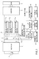
- a rectifier 2 is connected to a commercial AC power supply 1.
- An inverter 3 is connected to the output terminals P and N of the rectifier 2 by DC power supply lines L1 and L2.
- the inverter 3 is switched, converting the output voltage of the rectifier 2 (a DC voltage) to an AC voltage having a predetermined frequency.
- the output of the inverter 3 is supplied to a load 4.
- a battery unit 10 is connected between the DC power supply lines L1 and L2.
- the battery unit 10 comprises a plurality of storage batteries Sa, Sb, ... Sn, which are connected in series.
- Each storage battery is a sealed-type lead storage battery.
- the battery unit 10 can be operated in various modes, which are float charge mode, discharge mode and recharge mode.
- the voltage of the power supply (rectifier 2) is applied to the load (inverter 3) connected to the battery unit 10, and the battery unit 10 is recharged by virtue of the voltage of the power supply (rectifier 2).
- the voltage of the battery unit 10 is applied to the load (inverter 3) when the voltage of the power supply (rectifier 2) falls or is zero (when the supply of power is interrupted).
- the battery unit 10 is recharged by virtue of the voltage of the power supply (rectifier 2), after the battery unit has operated in the discharge mode.
- the rectifier 2, inverter 3 and battery unit 10 constitute an uninterruptible power supply system that keeps driving a load even if the commercially AC power supply 1 is interrupted.
- voltage detecting sections (first voltage detecting means) 11a, 11b, ... 11n are connected to the storage batteries Sa, Sb, ... Sn of the battery unit 10, respectively, to detecting the voltages V of the storage batteries Sa, Sb, ... Sn.
- a temperature detecting section 12 is provided for the battery unit 10.
- the temperature detecting section 12 has a temperature sensor 12a attached to the battery unit 10. The temperature sensor 12a detects the temperature T of the battery unit 10 (or the ambient temperature of the battery unit 10).
- a total voltage detecting section (second voltage detecting means) 13 is connected between the DC power supply lines L1 and L2, to detect the total voltage E of the battery unit 10.
- a measuring section 21, a parameter setting section 22, a display section 23, and an alarm generating section 24 are connected to a control section 20.
- the measuring section 21 performs A/D (analog-to-digital) conversion on the voltages V detected by the voltage detecting sections 11a, 11b, ... 11n, the temperature T detected by the temperature detecting section 12, and the voltage E detected by the total voltage detecting section 13, thereby generating digital data.
- the digital data is supplied to the control section 20.
- the parameter setting section 22 is designed to set various parameters for operating the control section 20.
- the display section 23 displays (informing) the results of operation of the control section 20.
- the alarm generating section 24 generates an alarm signal when the control section 20 detects a defect in any one of the storage batteries, detects an abnormal voltage in the battery unit 10, or determines that the death of any one of the storage batteries (namely, the death of the battery unit 10).
- the alarm signal is transmitted (or given) to a central control room where inspection-maintenance workers are stationed.
- the control section 20 has the following functional means [1] to [8]:
- time counts t 1 , t 2 , t 3 and t 4 are cleared (Step 101).
- the temperature of the battery unit 10 is detected (if YES in Step 100).
- the average (temperature of the battery unit 10) of the temperatures T that the temperature detecting section 12 has detected is calculated.
- the life of the storage batteries Sa, Sb, ... Sn are determined (Step 102). If any storage battery is found to have dead (if YES in Step 103), the display section 23 displays this event and the alarm generating section 24 generates an alarm signal (Step 104).
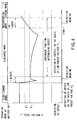
- the voltage E detected by the total voltage detecting section 13 may become equal to or higher than the predetermined maximum value Emax (if YES in Step 105), as in Case A illustrated in FIG. 8.
- the time count t 1 is started (Step 106).
- the time count t 1 reaches the prescribed value ta (if YES in Step 107)
- it is determined that the total voltage E is abnormal (Step 108).
- the display section 23 displays this event and the alarm generating section 24 generates an alarm signal (Step 109).
- the voltage E detected by the total voltage detecting section 13 may fall below predetermined minimum value Emin (if YES in Step 110), as in Case B illustrated in FIG. 8. If this happens, the time count t 2 is started (Step 111). When the time count t 2 reaches the prescribed value tb (if YES in Step 112), it is determined that the total voltage E is abnormal (Step 108). The display section 23 displays this event and the alarm generating section 24 generates an alarm signal (Step 109).
- the voltage E detected by the total voltage detecting section 13 (i.e., the total voltage) is compared with values E 1 and E 2 (E 1 ⁇ E 2 ), the value E 1 preset for detecting discharge and the value E 2 preset for detecting the end of discharge (Step 113).
- Step 114 If the voltage E detected is equal to or higher than the preset value E 2 (if YES in Step 113), it is determined that the battery unit 10 is operating in the float charge mode (Step 114). In this case, the low voltage V 2 and the high voltage V 3 are selected, both preset as reference values for detecting defects in the storage batteries (Step 115).
- the voltage V detected by any one of the voltage detecting sections 11a, 11b, ... 11n may fall below the low voltage V 2 as shown in FIG. 5, while the battery unit 10 is operating in the float charge mode. If so (if YES in Step 116), it is determined that the storage battery causing this voltage drop is defective (Step 118). The display section 23 displays this event and the alarm generating section 24 generates an alarm signal (Step 119).
- the voltage V detected by any one of the voltage detecting sections 11a, 11b, ... 11n may rises to or above the high voltage V 3 as shown in FIG. 7, while the battery unit 10 is operating in the float charge mode. If this happens (if NO in Step 116 and YES in Step 117), it is determined that the storage battery causing this voltage rise is defective (Step 118).
- the display section 23 displays this event and the alarm generating section 24 generates an alarm signal (Step 119).
- the voltage E detected may falls below the preset value E 2 (NO in Step 113) and may be lower than the preset value E 1 (Step 120). If so, it is determined that the battery unit 10 is operating in the discharge mode (Step 121). In this case, the low voltage value V 1 ( ⁇ V 2 ) is selected as reference for detecting a defect in each of the storage batteries (Step 122).
- the time count t 3 is started at the same time it is determined that the battery unit 10 is operating in the discharge mode (Step 123).
- the time count t 3 reaches one minute (i.e., the detecting masking time) (YES in Step 124)
- the voltages V detected by the voltage detecting sections 11a, 11b, ... 11n are compared with the low voltage value V 1 ( ⁇ V 2 ) selected (Step 125).
- Step 118 If any one of the voltages V detected is lower than the preset low voltage value V 1 bas shown in FIG. 6 (if YES in Step 125), it is determined that the storage battery causing this voltage drop is defective (Step 118).
- the display section 23 displays this event and the alarm generating section 24 generates an alarm signal (Step 119).
- Step 127 If the detected voltage E rises to or above the preset value E 1 (if NO in Step 120) and if the discharge mode is no longer valid (if YES in Step 126), it is determined that the battery unit 10 is operating in the recharge mode (Step 127). At the same time it is determined so, the time count t 4 is started (Step 128). Until the time count t 4 reaches 48 hours (if NO in Step 129), it is determined that recharge mode remains valid, regardless of changes in the detected voltage E (Step 127). Thus, for 48 hours corresponding to the time count t 4 , it is not determined whether or not a defect exists in each storage battery (detection masking).
- an abnormal voltage of the battery unit 10 and defects in the storage batteries Sa, Sb, ... Sn can be reliably detected without requiring the service of inspection-maintenance workers.
- the life of each storage battery can be determined and informed without requiring the service of inspection-maintenance workers.
- the battery unit 10 and the storage batteries Sa, Sb, ... Sn can be automatically managed with high reliability.
- the voltage detecting sections 11a, 11b, ... 11n are connected to the battery unit 10 and storage batteries Sa, Sb, ... Sn by means of the connecting device shown in FIGS. 9, 10 and 11. These figures illustrates only the connection of the storage battery Sa and the voltage detecting section 11a. Any other voltage detecting section is connected to the associated storage battery in the same manner.
- the storage battery Sa has a pair of bolt-shaped electrodes 41, which protrude from the upper surface of the sealed jar 40.
- An electrically conductive washer 30 is secured to each of the electrodes 41.
- a connecting member 50 known as "female tab,” is attached to the washer 30.
- a wire 58 is led from the female tab 50 and is connected to the voltage detecting section 11a.
- a nut 42 is mounted on each electrode 41 of the storage battery Sa.
- the washer 30 and a connecting member 60 are attached to each electrode 41 in the order mentioned, and the nut 42 is fastened, gripping the electrode 41.
- the wire 61 led from each connecting member 60 is connected to one electrode 41 of the next storage battery Sb.
- the washer 30 has a ring-shaped part 32 and a flat connecting strip 33.
- the strip 33 outwardly protrudes from the ring-shaped part 32 in the radial direction and can be attached to and removed from the electrode 41.
- the electrode 41 can pass through the hole 31 of the ring-shaped part 32.
- the connecting strip 33 has such shape and size that it can be sufficiently inserted in the female tab 50 even when the nut 42 is fastened, gripping the electrode 41.
- the female tab 50 comprises a housing 51 made of insulating material, a recess 52 made in one end of the housing 51, a pair of electrically conductive holding members 53 provided in the recess 52, a conductor 54 provided in the recess 52 and electrically connected to the holding members 53, a part-accommodating hole 55 extending from the bottom of the recess 52 to the proximal end 58a of a wire 58, and a series circuit composed of a fuse 56 and a resistor 57 which are provided in the part-accommodating hole 55.
- One end 56a of the fuse 56 is connected to the conductor 54.
- the other end of the fuse 56 is connected by the resistor 57 to the proximal end 58a of the wire 58.
- the resistor 57 functions as a protection resistor for preventing short-circuiting, if any in the load (i.e., wire 58 or voltage detecting section 11a), from changing the voltage of the storage battery Sa.
- the fuse 56 melts to prevent an excessively large current from flowing through the female tab 50 if short-circuiting or the like occurs in the load (i.e., wire 58 or voltage detecting section 11a).
- the recess 52 is formed so large that the connecting strip 33 can be fully inserted into it.
- Each holding member 53 has been formed by bending a thin metal plate having electrical conductivity.
- the holding members 53 work like leaf springs, reliably contacting and clamping the connecting strip 33 inserted in the recess 52. Due to the clamping, the washer 30 and the wire 58 are electrically connected to each other by the holding members 53, conductor 54, fuse 56 and resistor 57.
- Each holding member 53 is inclined or curved in the open end of the recess 52, so that the connecting strip 33 may be smoothly inserted into the recess 52.
- a washer 30 is fastened on each electrode 41 of the storage batter Sa, and a female tab 50 is attached to the connecting strip 33 of the washer 30.
- the storage battery Sa and the voltage detecting section 11a can thereby connected easily and reliably. That is, the voltage detecting section 11a can be easily connected to the storage battery Sa, without removing the nut 42 or the connecting member 60 from the electrode 41 and without suspending the operation of the uninterruptible power supply system. Further, the efficiency of connecting the section 11a to the battery Sa is enhanced.
- each holding members 53 of the female tab 50 reliably contacts the connecting strip 33 of the washer 30, stable and good electrical connection is maintained between the storage battery Sa and the voltage detecting section 11a.
- each female tab 50 has a resistor 57.
- each holding member 53 has been formed by bending a metal plate. Nonetheless, there is no limitation to the shape and the like of each holding member 53.
- the member 53 may have any shape, provided that it can reliably contact the connecting strip 33.
- one of the holding members 53 may be formed by bending a metal plate, and the other holding member 53 may be an insulating member made of rubber or the like.
- the apparatus described above is designed for use in an uninterruptible power supply system. Nevertheless, the apparatus can be used in any other system that has storage batteries.
Landscapes
- Physics & Mathematics (AREA)
- General Physics & Mathematics (AREA)
- Secondary Cells (AREA)
- Charge And Discharge Circuits For Batteries Or The Like (AREA)
Abstract
Description
The
The holding
Claims (12)
- An apparatus for managing a battery unit having a plurality of storage batteries, characterized by comprising:a plurality of first voltage detecting means (11a, 11b, ... 11n) for detecting voltages of the storage batteries (Sa, Sb, ... Sn), respectively;second voltage detecting means (13) for detecting a total voltage of the battery unit (10);defect detecting means (20) for detecting defects in the storage batteries (Sa, Sb, ... Sn) on the basis of the voltages detected by the first voltage detecting means (11a, 11b, . .. 11n);abnormality detecting means (20) for detecting an abnormal voltage in the battery unit (10) on the basis of the voltage detected by the second voltage detecting means;temperature detecting means (12) for detecting temperature in the battery unit (10);battery life determining means (20) for determining a life of each of the storage batteries (Sa, Sb, ... Sn) has dead, on the basis of the temperature detected by the temperature detecting means (12); andinformation means (23) for informing results of the detection performed by the defect detecting means (20) and abnormality detecting means (20) and results of the determination made by the battery life determining means (20).
- An apparatus according to claim 1, characterized in that the storage batteries (Sa, Sb, ... Sn) are sealed-type lead storage batteries and are connected in series.
- An apparatus according to claim 1, characterized by further comprising operating mode determining means (20) for determining an operation mode of the battery unit (10).
- An apparatus according to claim 3, characterized in that the defect detecting means (20) detects defects in the storage batteries (Sa, Sb, ... Sn) by comparing the voltages detected by the first voltage detecting means (11a, 11b, ... 11n) with a level set on the basis of the operation mode determined by the operating mode determining means (20).
- An apparatus according to claim 3, characterized in that the abnormality detecting means (20) detects an abnormal voltage in the battery unit (10) by comparing the voltage detected by the second voltage-detecting means (13) with a predetermined upper-limit value and by comparing the voltage detected by the second voltage-detecting means (13) with a predetermined lower-limit value.
- An apparatus according to claim 3, characterized in that the operating mode determining means (20) determines in which operation mode the battery unit (10) is operating, float charge mode, discharge mode, or recharge mode, on the basis of the voltage detected by the second voltage detecting means (13); in said float charge mode, the voltage of a power supply (2) connected to the battery unit (10) is applied to a load (3) connected to the battery unit (10), and the battery unit (10) is charged by virtue of the voltage of the power supply (2); in said discharge mode, the voltage of the battery unit (10) is applied to the load (3) when the voltage of the power supply (2) falls or is zero; and in said recharge mode, the battery unit (10) is recharged by virtue of the voltage of the power supply (2) after the battery unit (10) has operated in the discharge mode.
- An apparatus according to claim 6, characterized in that the defect detecting means (20) comprises first defect detecting means, second defect detecting means, and third defect detecting means; said first detect detecting means detects detects in the storage batteries (Sa, Sb, ... Sn) in accordance with whether the voltages detected by the first voltage detecting means (11a, 11b, ... 11n) are lower than a predetermined low voltage V2, when the operation mode determined by the operation mode determining means is the float charge mode; said second detect detecting means detects defects in the storage batteries (Sa, Sb, ... Sn) in accordance with whether the voltages detected by the first voltage detecting means (11a, 11b, ... 11n) are equal to or higher than a predetermined high voltage V3, when the operation mode determined by the operation mode determining means is the float charge mode; and the third defect detecting means for detecting defects in the storage batteries (Sa, Sb, ... Sn) in accordance with whether the voltages detected by the first voltage detecting means (11a, 11b, ... 11n) are lower than a predetermined low voltage V1 (< V2) upon lapse of a prescribed time from the start of the discharge mode, when the operation mode determined (20) by the operation mode determining means is the discharge mode.
- An apparatus according to claim 6, characterized in that the abnormality detecting means (20) comprises first abnormality detecting means and second abnormality detecting means; said first abnormality detecting means detects an abnormal voltage in the battery unit (10) in accordance with whether the voltage detected by the second voltage detecting means (13) remains equal to or higher than a predetermined maximum value for a prescribed time; and the second abnormality detecting means for detecting an abnormal voltage in the battery unit (10) in accordance with whether the voltage detected by the second voltage detecting means (13) remains lower than a predetermined minimum value for a prescribed time.
- An apparatus according to claim 1, characterized in that each of said storage batteries (Sa, Sb, ... Sn) has a pair of electrodes (41).
- An apparatus according to claim 9, characterized by further comprising connecting devices, each for the connecting one electrodes (41) of one storage battery to one first voltage detecting means.
- An apparatus according to claim 10, characterized in that each of the connecting devices comprises a washer (30) to be removably attached to one electrode (41), a connecting member (50) to be removably connected to the washer (30), and a wire (58) extending from the connecting member (50).
- An apparatus according to claim 11, characterized in that the washer (30) has a ring-shaped part (32) and a connecting strip (33) extending outwardly from the ring-shaped part (32) in a radial direction thereof; the connecting member (50) has a recess (52) for receiving and holding the connecting strip (33) of the washer (30) and a series circuit provided between the recess (52) and the wire (58) and composed of a fuse (56) and a resistor (57); and series circuit connects the connecting strip (33) to the wire (58) when the connecting strip (33) is inserted into the recess (52).
Applications Claiming Priority (4)
| Application Number | Priority Date | Filing Date | Title |
|---|---|---|---|
| JP21267198 | 1998-07-28 | ||
| JP21267198A JP4044217B2 (en) | 1998-07-28 | 1998-07-28 | Battery management device |
| JP21744198A JP3703973B2 (en) | 1998-07-31 | 1998-07-31 | Mail tab and connecting member using the same |
| JP21744198 | 1998-07-31 |
Publications (3)
| Publication Number | Publication Date |
|---|---|
| EP0977047A2 true EP0977047A2 (en) | 2000-02-02 |
| EP0977047A3 EP0977047A3 (en) | 2000-04-26 |
| EP0977047B1 EP0977047B1 (en) | 2008-08-06 |
Family
ID=26519354
Family Applications (1)
| Application Number | Title | Priority Date | Filing Date |
|---|---|---|---|
| EP99114682A Expired - Lifetime EP0977047B1 (en) | 1998-07-28 | 1999-07-27 | Apparatus for managing a battery unit having storage batteries |
Country Status (6)
| Country | Link |
|---|---|
| US (1) | US6014012A (en) |
| EP (1) | EP0977047B1 (en) |
| KR (1) | KR100730335B1 (en) |
| CN (1) | CN1163759C (en) |
| DE (1) | DE69939240D1 (en) |
| MY (1) | MY117546A (en) |
Cited By (7)
| Publication number | Priority date | Publication date | Assignee | Title |
|---|---|---|---|---|
| WO2001073914A3 (en) * | 2000-03-29 | 2002-07-11 | Powerware Corp | System for detecting defective battery packs |
| EP1455195A1 (en) * | 2003-03-04 | 2004-09-08 | Saft, Sa | Improved apparatus and method to control the voltage of electrochemical generators for a rechargable battery |
| EP1150132B1 (en) * | 2000-04-28 | 2005-08-10 | Matsushita Electric Industrial Co., Ltd. | Method of replacing secondary battery |
| EP2725684A4 (en) * | 2011-05-25 | 2015-07-08 | Nec Energy Devices Ltd | BATTERY DEVICE |
| CN105071453A (en) * | 2015-10-08 | 2015-11-18 | 河南行知专利服务有限公司 | Battery management system |
| EP2091101A4 (en) * | 2006-11-06 | 2018-01-24 | NEC Corporation | Unit battery for battery pack, battery control system, and battery control method |
| EP3796016A1 (en) * | 2019-09-09 | 2021-03-24 | General Electric Company | System and method for detecting battery faults in a pitch system of a wind turbine |
Families Citing this family (18)
| Publication number | Priority date | Publication date | Assignee | Title |
|---|---|---|---|---|
| WO2001017053A1 (en) * | 1999-09-01 | 2001-03-08 | Fujitsu Limited | Battery management circuit |
| KR100397359B1 (en) * | 2001-02-08 | 2003-09-13 | 주식회사 맥사이언스 | Assembly method of battery pack by sorting battery |
| US6875964B2 (en) | 2002-05-07 | 2005-04-05 | Ford Motor Company | Apparatus for electromagnetic forming, joining and welding |
| US8471532B2 (en) | 2002-11-22 | 2013-06-25 | Milwaukee Electric Tool Corporation | Battery pack |
| US7589500B2 (en) * | 2002-11-22 | 2009-09-15 | Milwaukee Electric Tool Corporation | Method and system for battery protection |
| CN1306675C (en) * | 2002-12-26 | 2007-03-21 | 北京机电研究所 | Equipment for managing accumulator battery of motive power utilized in electric automobile |
| JP4088603B2 (en) * | 2004-03-29 | 2008-05-21 | 富士フイルム株式会社 | Device combination system |
| US8120325B2 (en) * | 2007-08-10 | 2012-02-21 | Sony Ericsson Mobile Communications Ab | Battery short circuit monitoring |
| DE102009050125A1 (en) * | 2009-10-21 | 2011-04-28 | Continental Automotive Gmbh | Electric energy storage with integrated deep discharge device |
| JP5448865B2 (en) | 2010-01-18 | 2014-03-19 | 三菱重工業株式会社 | Battery system |
| WO2013162500A1 (en) * | 2012-04-23 | 2013-10-31 | Hewlett-Packard Development Company, L.P. | Moderating a charging |
| CN102856976A (en) * | 2012-09-25 | 2013-01-02 | 广东易事特电源股份有限公司 | A kind of uninterruptible power supply, battery management system and uninterruptible power supply system |
| CN103208644B (en) * | 2013-03-22 | 2015-10-14 | 超威电源有限公司 | A kind of accumulator pole group enters slot device |
| KR101699198B1 (en) * | 2013-04-12 | 2017-01-23 | 도시바 미쓰비시덴키 산교시스템 가부시키가이샤 | Electricity storage device abnormality detection circuit, and electricity storage device provided with same |
| CN105164541B (en) * | 2013-04-26 | 2018-04-06 | 日立汽车系统株式会社 | Battery monitoring apparatus and the battery system using the battery monitoring apparatus |
| CN104714175A (en) * | 2013-12-12 | 2015-06-17 | 北京有色金属研究总院 | Battery system fault diagnosis method and system |
| RU2663087C2 (en) * | 2014-03-10 | 2018-08-01 | Чанз Асендинг Энтерпрайз Ко., Лтд. | Determination of battery serviceability without turning it off without warning |
| EP3406893B1 (en) * | 2017-05-25 | 2025-07-23 | General Electric Renovables España, S.L. | System and method for estimating consumed battery life of a pitch system of a wind turbine |
Family Cites Families (8)
| Publication number | Priority date | Publication date | Assignee | Title |
|---|---|---|---|---|
| JPH07120535B2 (en) * | 1989-03-23 | 1995-12-20 | 株式会社ユアサコーポレーション | Lead storage battery life judgment method |
| JP2936441B2 (en) * | 1992-05-14 | 1999-08-23 | 松下電器産業株式会社 | Calculation method of capacity deterioration rate of storage battery and deterioration diagnosis device |
| EP0609101B1 (en) * | 1993-01-29 | 2002-06-26 | Canon Kabushiki Kaisha | Electric power accumulating apparatus and electric power system |
| JPH07298503A (en) * | 1994-04-20 | 1995-11-10 | Fuji Electric Co Ltd | Battery quality judgment device for uninterruptible power supply |
| JPH09129271A (en) * | 1995-11-02 | 1997-05-16 | Japan Storage Battery Co Ltd | Battery life determination device |
| FR2742601B1 (en) * | 1995-12-15 | 1998-01-09 | Renault | ACCUMULATOR BATTERY MANAGEMENT SYSTEM |
| US5710503A (en) * | 1996-02-01 | 1998-01-20 | Aims Systems, Inc. | On-line battery monitoring system with defective cell detection capability |
| EP0958632A4 (en) * | 1996-07-17 | 2002-03-06 | Duracell Inc | OPERATING SYSTEM FOR BATTERY |
-
1999
- 1999-03-10 US US09/265,200 patent/US6014012A/en not_active Expired - Lifetime
- 1999-07-06 CN CNB991096932A patent/CN1163759C/en not_active Expired - Fee Related
- 1999-07-27 EP EP99114682A patent/EP0977047B1/en not_active Expired - Lifetime
- 1999-07-27 DE DE69939240T patent/DE69939240D1/en not_active Expired - Lifetime
- 1999-07-27 MY MYPI99003164A patent/MY117546A/en unknown
- 1999-07-28 KR KR1019990030742A patent/KR100730335B1/en not_active Expired - Fee Related
Cited By (10)
| Publication number | Priority date | Publication date | Assignee | Title |
|---|---|---|---|---|
| WO2001073914A3 (en) * | 2000-03-29 | 2002-07-11 | Powerware Corp | System for detecting defective battery packs |
| US7132833B2 (en) | 2000-03-29 | 2006-11-07 | Powerware Corporation | System for detecting defective battery packs |
| EP1150132B1 (en) * | 2000-04-28 | 2005-08-10 | Matsushita Electric Industrial Co., Ltd. | Method of replacing secondary battery |
| EP1455195A1 (en) * | 2003-03-04 | 2004-09-08 | Saft, Sa | Improved apparatus and method to control the voltage of electrochemical generators for a rechargable battery |
| FR2852149A1 (en) * | 2003-03-04 | 2004-09-10 | Cit Alcatel | IMPROVED DEVICE AND METHOD FOR CONTROLLING THE VOLTAGE OF ELECTROCHEMICAL GENERATORS OF RECHARGEABLE BATTERY |
| EP2091101A4 (en) * | 2006-11-06 | 2018-01-24 | NEC Corporation | Unit battery for battery pack, battery control system, and battery control method |
| EP2725684A4 (en) * | 2011-05-25 | 2015-07-08 | Nec Energy Devices Ltd | BATTERY DEVICE |
| CN105071453A (en) * | 2015-10-08 | 2015-11-18 | 河南行知专利服务有限公司 | Battery management system |
| EP3796016A1 (en) * | 2019-09-09 | 2021-03-24 | General Electric Company | System and method for detecting battery faults in a pitch system of a wind turbine |
| US11476685B2 (en) | 2019-09-09 | 2022-10-18 | General Electric Company | System and method for detecting battery faults in a pitch system of a wind turbine |
Also Published As
| Publication number | Publication date |
|---|---|
| KR100730335B1 (en) | 2007-06-19 |
| MY117546A (en) | 2004-07-31 |
| EP0977047B1 (en) | 2008-08-06 |
| US6014012A (en) | 2000-01-11 |
| CN1243255A (en) | 2000-02-02 |
| CN1163759C (en) | 2004-08-25 |
| DE69939240D1 (en) | 2008-09-18 |
| EP0977047A3 (en) | 2000-04-26 |
| KR20000012021A (en) | 2000-02-25 |
Similar Documents
| Publication | Publication Date | Title |
|---|---|---|
| EP0977047B1 (en) | Apparatus for managing a battery unit having storage batteries | |
| EP1099119B1 (en) | Signalling system | |
| US6404166B1 (en) | Signalling system | |
| US6198253B1 (en) | Smart battery with maintenance and testing functions, communications, and display | |
| CA2121471C (en) | Monitoring system for batteries during charge and discharge | |
| KR20020064998A (en) | System and method for determining battery state-of-health | |
| JPH08506477A (en) | Device and method for dynamic adjustment and monitoring of a storage battery pack | |
| US20020018927A1 (en) | Battery having discharge state indication | |
| KR20230035408A (en) | A rechargeable battery discharging device for discharging rechargeable batteries, and a method for discharging a plurality of rechargeable batteries. | |
| GB2397656A (en) | Battery monitoring system | |
| CN101460859A (en) | Method for judging abnormality of battery pack, and battery pack | |
| CN104655907B (en) | Battery pack voltage check device | |
| CN1222001A (en) | Equipment power supply system and evaluation method to service life and accumulation capacity of accumulating device | |
| KR20100131342A (en) | Distribution Automation System Using Uninterruptible Power Supply | |
| CN114362278A (en) | Battery pack | |
| JP4949139B2 (en) | Battery power system | |
| EP1278072A1 (en) | Device for judging life of auxiliary battery | |
| US4625201A (en) | Emergency battery cell monitor | |
| JPH08308119A (en) | Battery charging system | |
| US6103408A (en) | Electric battery | |
| JP5034859B2 (en) | Battery status display system | |
| JPH1118314A (en) | Method and equipment for charging lithium ion secondary battery | |
| JP4044217B2 (en) | Battery management device | |
| JPH05326032A (en) | Battery abnormality detection method | |
| WO2019088264A1 (en) | Management device, power storage device, cause analysis method, engine driven vehicle, and electric automobile |
Legal Events
| Date | Code | Title | Description |
|---|---|---|---|
| PUAI | Public reference made under article 153(3) epc to a published international application that has entered the european phase |
Free format text: ORIGINAL CODE: 0009012 |
|
| AK | Designated contracting states |
Kind code of ref document: A2 Designated state(s): DE FR GB |
|
| AX | Request for extension of the european patent |
Free format text: AL;LT;LV;MK;RO;SI |
|
| RIN1 | Information on inventor provided before grant (corrected) |
Inventor name: KAWAGOE, YUJI, C/O NIPPON T. AND T. EAST CORP. Inventor name: TSUJIKAWA, TOMONOBU, C/O NTT POWER AND BUILDING Inventor name: MOTOZU, TAMOTSU, C/O NTT POWER AND BUILDING F. IN Inventor name: MURAO, TETSURO, C/O NTT POWER AND BUILDING F. INC. |
|
| PUAL | Search report despatched |
Free format text: ORIGINAL CODE: 0009013 |
|
| AK | Designated contracting states |
Kind code of ref document: A3 Designated state(s): AT BE CH CY DE DK ES FI FR GB GR IE IT LI LU MC NL PT SE |
|
| AX | Request for extension of the european patent |
Free format text: AL;LT;LV;MK;RO;SI |
|
| 17P | Request for examination filed |
Effective date: 20000921 |
|
| AKX | Designation fees paid |
Free format text: DE FR GB |
|
| 17Q | First examination report despatched |
Effective date: 20060703 |
|
| GRAP | Despatch of communication of intention to grant a patent |
Free format text: ORIGINAL CODE: EPIDOSNIGR1 |
|
| GRAS | Grant fee paid |
Free format text: ORIGINAL CODE: EPIDOSNIGR3 |
|
| GRAA | (expected) grant |
Free format text: ORIGINAL CODE: 0009210 |
|
| AK | Designated contracting states |
Kind code of ref document: B1 Designated state(s): DE FR GB |
|
| REG | Reference to a national code |
Ref country code: GB Ref legal event code: FG4D |
|
| REF | Corresponds to: |
Ref document number: 69939240 Country of ref document: DE Date of ref document: 20080918 Kind code of ref document: P |
|
| PLBE | No opposition filed within time limit |
Free format text: ORIGINAL CODE: 0009261 |
|
| STAA | Information on the status of an ep patent application or granted ep patent |
Free format text: STATUS: NO OPPOSITION FILED WITHIN TIME LIMIT |
|
| 26N | No opposition filed |
Effective date: 20090507 |
|
| PGFP | Annual fee paid to national office [announced via postgrant information from national office to epo] |
Ref country code: FR Payment date: 20100623 Year of fee payment: 12 |
|
| PGFP | Annual fee paid to national office [announced via postgrant information from national office to epo] |
Ref country code: GB Payment date: 20100721 Year of fee payment: 12 |
|
| PGFP | Annual fee paid to national office [announced via postgrant information from national office to epo] |
Ref country code: DE Payment date: 20100929 Year of fee payment: 12 |
|
| GBPC | Gb: european patent ceased through non-payment of renewal fee |
Effective date: 20110727 |
|
| REG | Reference to a national code |
Ref country code: FR Ref legal event code: ST Effective date: 20120330 |
|
| PG25 | Lapsed in a contracting state [announced via postgrant information from national office to epo] |
Ref country code: FR Free format text: LAPSE BECAUSE OF NON-PAYMENT OF DUE FEES Effective date: 20110801 Ref country code: DE Free format text: LAPSE BECAUSE OF NON-PAYMENT OF DUE FEES Effective date: 20120201 |
|
| REG | Reference to a national code |
Ref country code: DE Ref legal event code: R119 Ref document number: 69939240 Country of ref document: DE Effective date: 20120201 |
|
| PG25 | Lapsed in a contracting state [announced via postgrant information from national office to epo] |
Ref country code: GB Free format text: LAPSE BECAUSE OF NON-PAYMENT OF DUE FEES Effective date: 20110727 |