EP0977046B1 - Method and apparatus for testing the quality of the vacuum in a vacuum switch - Google Patents
Method and apparatus for testing the quality of the vacuum in a vacuum switch Download PDFInfo
- Publication number
- EP0977046B1 EP0977046B1 EP19990202407 EP99202407A EP0977046B1 EP 0977046 B1 EP0977046 B1 EP 0977046B1 EP 19990202407 EP19990202407 EP 19990202407 EP 99202407 A EP99202407 A EP 99202407A EP 0977046 B1 EP0977046 B1 EP 0977046B1
- Authority
- EP
- European Patent Office
- Prior art keywords
- switch
- vacuum
- capacitor
- contacts
- quality
- Prior art date
- Legal status (The legal status is an assumption and is not a legal conclusion. Google has not performed a legal analysis and makes no representation as to the accuracy of the status listed.)
- Expired - Lifetime
Links
Images


Classifications
-
- H—ELECTRICITY
- H01—ELECTRIC ELEMENTS
- H01H—ELECTRIC SWITCHES; RELAYS; SELECTORS; EMERGENCY PROTECTIVE DEVICES
- H01H33/00—High-tension or heavy-current switches with arc-extinguishing or arc-preventing means
- H01H33/60—Switches wherein the means for extinguishing or preventing the arc do not include separate means for obtaining or increasing flow of arc-extinguishing fluid
- H01H33/66—Vacuum switches
- H01H33/668—Means for obtaining or monitoring the vacuum
-
- G—PHYSICS
- G01—MEASURING; TESTING
- G01R—MEASURING ELECTRIC VARIABLES; MEASURING MAGNETIC VARIABLES
- G01R31/00—Arrangements for testing electric properties; Arrangements for locating electric faults; Arrangements for electrical testing characterised by what is being tested not provided for elsewhere
- G01R31/327—Testing of circuit interrupters, switches or circuit-breakers
- G01R31/3271—Testing of circuit interrupters, switches or circuit-breakers of high voltage or medium voltage devices
- G01R31/3272—Apparatus, systems or circuits therefor
Definitions
- the present invention relates to a method for testing the quality of the vacuum in a vacuum switch, comprising of supplying a quantity of electrical charge to the contacts of the vacuum switch while the contacts are moved toward each other, and monitoring the progression of the voltage over or the current through the switch.
- This method is used to measure the quality of the vacuum in a vacuum switch.
- Vacuum switches have been in use for some decades. They are evacuated during production and then sealed in gas-tight manner. The quality of the vacuum may deteriorate during the lifetime of such vacuum switches.
- the present invention provides a method wherein the circuit-breaking conditions are simulated as precisely as possible.
- the progression of the current in the arc phase greatly depends herein on the synchronization between the generator for the high-frequency switch current and the mechanical operation of the switch, whereby it is possible to achieve reproducible measurement results.
- the quantity of charge is preferably supplied from a charged capacitor. This results in a simple and safe embodiment, wherein the danger of destruction of the switch is avoided as far as possible.
- the generator comprises an initially charged capacitor which serves as generator during generation of the current through the switch.
- the current generated by the capacitor is therefore always decreasing. This also results in indeterminate conditions during opening of the contacts of the switch.
- the capacitor is spontaneously discharged by the switching operation, so that the charged condition of the capacitor is well defined at each measurement.
- the charge is supplied via an inductance.
- the combination of a capacitor and an inductance results in a resonant circuit, the resonance frequency of which is at least two orders of magnitude greater than the mains frequency.
- the time between ignition of the discharge and contact touch is herein also sufficiently long.
- the progression of the current through or the voltage over the switch is monitored by determining at least one of these quantities and subsequently deriving the quality of the vacuum from the monitored quantity.
- the present invention further provides such a method, wherein the switch is incorporated in a switch bay, the switch is transported together with the drive mechanism out of the switch bay and the method according to any of the foregoing claims is then performed.
- the present invention provides a device for monitoring the quality of the vacuum in a vacuum switch, comprising:
- This device enables the method according to the present invention to be applied with little equipment.
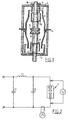
- FIG. 1 shows a vacuum switch 1 which is formed by a gastight housing formed by a housing 2 generally manufactured from ceramic material, a bottom plate 3 and a cover 4.
- the housing 2 is divided into two pieces separated by a ring 5 for positioning of a shield 6 in the switch housing.
- a capacitor C1 is herein used, one side of which is connected via an inductance L1 to one contact of the switch, while the other side of capacitor C1 is connected to the other side of the switch.
- a voltmeter V is further arranged which is connected to measure the voltage over the switch and an ammeter A is arranged to measure the current through the switch. It will be apparent that both instruments are recording instruments, for instance in the form of an oscilloscope, digital recorder and so on.
- a capacitor C2 to adjust the recovery voltage.
- the capacitor C1 is charged with a charging circuit not shown in the drawing; this can simply be formed by a rectifier followed by a charging resistance. Contacts 8, 11 are herein in the opened position. The charging circuit is then isolated and a switch-on command is given. At a given moment, depending on the distance between the contacts, flash-over will herein occur, whereafter capacitor C1 discharges over the switch contacts. After interruption of the discharge current, charging of capacitor C2 will take place so that once the initial discharge has taken place a recovery voltage is applied over the contacts.
- a measure can be derived for the circuit-breaking capacity of the vacuum switch from the moment at which the discharge is extinguished.
- FIG. 3A, 3B show the progression of the current through respectively the voltage over the switch when gas has leaked in.
- FIGS. 4A respectively 4B show the same quantities of a switch in which a good vacuum prevails.
Landscapes
- Physics & Mathematics (AREA)
- General Physics & Mathematics (AREA)
- Measuring Fluid Pressure (AREA)
Description
- The present invention relates to a method for testing the quality of the vacuum in a vacuum switch, comprising of supplying a quantity of electrical charge to the contacts of the vacuum switch while the contacts are moved toward each other, and monitoring the progression of the voltage over or the current through the switch.
- Such a method is known from the journal article "Pressure Estimation in Vacuum Circuit Breakers", G.C. Damstra et al, IEEE Transactions on Dielectrics and Electrical Insulation, vol. 2, no. 2, April 1995.
- This method is used to measure the quality of the vacuum in a vacuum switch.
- Vacuum switches have been in use for some decades. They are evacuated during production and then sealed in gas-tight manner. The quality of the vacuum may deteriorate during the lifetime of such vacuum switches.
- It will be apparent that it is of the greatest importance that the qualities for circuit-breaking of the short-circuiting currents for which the switch is dimensioned must remain unimpaired. The quality of the vacuum is an important factor here. Because, as stated, the vacuum may deteriorate during the lifetime of the switch, it is important to determine the quality of the vacuum.
- According to the above described method the quality of the vacuum cannot be determined.
- Experience has shown that adsorption of gas atoms in the switch takes place particularly through the contacts. During measurement of the vacuum with the above stated method these adsorbed atoms are not released. This measurement is hereby found not to be a good reflection of the phenomena occurring during circuit-breaking of short-circuiting currents. Desorption of the atoms and molecules from the contacts in fact takes place here, whereby the quality of the vacuum is greatly reduced during switching and the circuit-breaking capacity is greatly decreased.
- Nor does a high-voltage test of the breakdown voltage indicate a reduced circuit-breaking capacity.
- The present invention provides a method wherein the circuit-breaking conditions are simulated as precisely as possible.
- This objective is achieved by the above stated method, wherein the quantity of electrical charge is chosen such that adsorbed gas is released from the contacts.
- As a result of these measures a good simulation of the phenomena occurring during circuit-breaking of short-circuiting power takes place during the measurement in accordance with the method according to the invention, so that a good indication is obtained of the quality of the switch.
- It is pointed out here that a method is known from DE-A-36 43 672 for measuring the quality of the vacuum in a vacuum switch.
- In this known method a high-frequency current is conducted through the closed contacts. The contacts are subsequently opened and the progression of the current through the switch is measured.
- The progression of the current in the arc phase greatly depends herein on the synchronization between the generator for the high-frequency switch current and the mechanical operation of the switch, whereby it is possible to achieve reproducible measurement results.
- In the method according to the invention on the other hand, closing of the contacts forms the initiation of the measurement; there are no problems of synchronization.
- The quantity of charge is preferably supplied from a charged capacitor. This results in a simple and safe embodiment, wherein the danger of destruction of the switch is avoided as far as possible.
- In the prior art according to DE-A-36 43 672 the generator comprises an initially charged capacitor which serves as generator during generation of the current through the switch. The current generated by the capacitor is therefore always decreasing. This also results in indeterminate conditions during opening of the contacts of the switch.
- According to the invention however, the capacitor is spontaneously discharged by the switching operation, so that the charged condition of the capacitor is well defined at each measurement.
- According to another preferred embodiment the charge is supplied via an inductance.
- The combination of a capacitor and an inductance results in a resonant circuit, the resonance frequency of which is at least two orders of magnitude greater than the mains frequency. The time between ignition of the discharge and contact touch is herein also sufficiently long.
- When sufficient charge is transported the desorption capacity of the measuring method becomes sufficiently large.
- It is particularly important in the case of an alternating current switch that no re-ignition takes place during circuit-breaking, when the arc between contacts has disappeared as a result of the zero passage of current. In order to also enable simulation of this situation which occurs in reality the charge charges a capacitor which is arranged parallel to the switch and which applies a voltage to the switch immediately after the zero passage.
- According to another preferred embodiment the progression of the current through or the voltage over the switch is monitored by determining at least one of these quantities and subsequently deriving the quality of the vacuum from the monitored quantity.
- Good monitoring of the phenomena, which generally occur very rapidly, hereby becomes possible so that the behaviour of the switch can be properly inspected and documented.
- The present invention further provides such a method, wherein the switch is incorporated in a switch bay, the switch is transported together with the drive mechanism out of the switch bay and the method according to any of the foregoing claims is then performed.
- When the switch is transported out of the bay it is in any case isolated relative to the network in which the switch is normally included, so that the switch is per se available for testing.
- Finally, the present invention provides a device for monitoring the quality of the vacuum in a vacuum switch, comprising:
- a first capacitor;
- a charging circuit for charging the capacitor;
- means for connecting the first capacitor to the contacts of the switch; and
- monitoring means for monitoring the progression of the current through or the voltage over the switch.
- This device enables the method according to the present invention to be applied with little equipment.
- The present invention will be elucidated hereinbelow with reference to the annexed figures, in which:
- figure 1 shows a cross-sectional view of a vacuum switch;
- figure 2 shows a diagram of the measuring circuit according.to the invention;
- figures 3A, 3B show diagrams of the progression of current respectively voltage and measurement according to the invention at an increased gas pressure in the vacuum switch; and
- figures 4A, 4B show diagrams of the progression of current respectively voltage in the case of a good vacuum in the switch.
-
- Figure 1 shows a
vacuum switch 1 which is formed by a gastight housing formed by a housing 2 generally manufactured from ceramic material, a bottom plate 3 and a cover 4. In the present case the housing 2 is divided into two pieces separated by a ring 5 for positioning of a shield 6 in the switch housing. - Arranged in the bottom is an opening through which is inserted a rod 7 on which is mounted a fixed contact 8. In cover 4 is arranged an opening in which is placed a bearing 9 through which a
rod 10 is movable in axial direction. Amovable contact 11 is mounted onrod 10. The gastight closure between cover 4 androd 10 is ensured by abellows 12. Shields 13 respectively 14 are further arranged in the switch to collect metal vapour. - During the measurement according to the present invention use is made of the measuring circuit shown in figure 2. A capacitor C1 is herein used, one side of which is connected via an inductance L1 to one contact of the switch, while the other side of capacitor C1 is connected to the other side of the switch. A voltmeter V is further arranged which is connected to measure the voltage over the switch and an ammeter A is arranged to measure the current through the switch. It will be apparent that both instruments are recording instruments, for instance in the form of an oscilloscope, digital recorder and so on.
- According to a preferred embodiment use is made of a capacitor C2 to adjust the recovery voltage.
- In order to perform the method according to the present invention the capacitor C1 is charged with a charging circuit not shown in the drawing; this can simply be formed by a rectifier followed by a charging resistance.
Contacts 8, 11 are herein in the opened position. The charging circuit is then isolated and a switch-on command is given. At a given moment, depending on the distance between the contacts, flash-over will herein occur, whereafter capacitor C1 discharges over the switch contacts. After interruption of the discharge current, charging of capacitor C2 will take place so that once the initial discharge has taken place a recovery voltage is applied over the contacts. - A measure can be derived for the circuit-breaking capacity of the vacuum switch from the moment at which the discharge is extinguished.
- Various aspects are further elucidated in figures 3A, 3B which show the progression of the current through respectively the voltage over the switch when gas has leaked in.
- Figures 4A respectively 4B show the same quantities of a switch in which a good vacuum prevails.
Claims (7)
- Method for testing the quality of a vacuum in a vacuum switch, comprising of supplying a quantity of electrical charge to the contacts of the vacuum switch while the contacts are moved toward each other, and monitoring the progression of the voltage over or the current through the switch, characterized in that the quantity of electrical charge is chosen such that adsorbed gas is released from the contacts.
- Method as claimed in claim 1, characterized in that the quantity of charge is supplied from a charged capacitor.
- Method as claimed in claim 1 or 2, characterized in that the charge is supplied via an inductance, the value of which is chosen such that the resonance frequency is greater than the nominal mains frequency.
- Method as claimed in claim 3, characterized in that the charge charges a second capacitor arranged parallel to the switch, which second capacitor applies a voltage to the switch immediately after extinguishing of the discharge.
- Method as claimed in any of the foregoing claims, characterized in that the progression of the current through or the voltage over the switch is monitored by determining at least one of these quantities and subsequently deriving the quality of the vacuum from the monitored quantity.
- Method as claimed in any of the foregoing claims, characterized in that the switch is incorporated in a switch bay, is initially isolated from the switch bay and the method according to any of the foregoing claims is then performed.
- Device for monitoring the quality of the vacuum in a vacuum switch, comprising:a first capacitor;a charging circuit for charging the capacitor;means for connecting the first capacitor to the contacts of the switch; andmonitoring means for monitoring the progression of the current through or the voltage over the switch.
Applications Claiming Priority (2)
| Application Number | Priority Date | Filing Date | Title |
|---|---|---|---|
| NL1009741 | 1998-07-27 | ||
| NL1009741A NL1009741C2 (en) | 1998-07-27 | 1998-07-27 | Method and device for examining the quality of the vacuum in a vacuum switch. |
Publications (2)
| Publication Number | Publication Date |
|---|---|
| EP0977046A1 EP0977046A1 (en) | 2000-02-02 |
| EP0977046B1 true EP0977046B1 (en) | 2005-03-02 |
Family
ID=19767564
Family Applications (1)
| Application Number | Title | Priority Date | Filing Date |
|---|---|---|---|
| EP19990202407 Expired - Lifetime EP0977046B1 (en) | 1998-07-27 | 1999-07-21 | Method and apparatus for testing the quality of the vacuum in a vacuum switch |
Country Status (3)
| Country | Link |
|---|---|
| EP (1) | EP0977046B1 (en) |
| DE (1) | DE69923889T2 (en) |
| NL (1) | NL1009741C2 (en) |
Families Citing this family (2)
| Publication number | Priority date | Publication date | Assignee | Title |
|---|---|---|---|---|
| CN102087171A (en) * | 2009-12-04 | 2011-06-08 | 江苏省电力公司南京供电公司 | Junction box for switch mechanical characteristic tester |
| CN104049184B (en) * | 2014-04-18 | 2017-01-04 | 清华大学 | A kind of detection device of contact of breaker gap dynamic media strength characteristics |
Family Cites Families (2)
| Publication number | Priority date | Publication date | Assignee | Title |
|---|---|---|---|---|
| CH598353A5 (en) * | 1976-10-19 | 1978-04-28 | Sprecher & Schuh Ag | |
| DE3643672A1 (en) * | 1986-12-20 | 1988-06-30 | Bbc Brown Boveri & Cie | Method for testing the vacuum switching chamber of a vacuum switch and device for carrying out the method |
-
1998
- 1998-07-27 NL NL1009741A patent/NL1009741C2/en not_active IP Right Cessation
-
1999
- 1999-07-21 DE DE69923889T patent/DE69923889T2/en not_active Expired - Fee Related
- 1999-07-21 EP EP19990202407 patent/EP0977046B1/en not_active Expired - Lifetime
Also Published As
| Publication number | Publication date |
|---|---|
| NL1009741C2 (en) | 2000-01-28 |
| DE69923889D1 (en) | 2005-04-07 |
| EP0977046A1 (en) | 2000-02-02 |
| DE69923889T2 (en) | 2006-02-16 |
Similar Documents
| Publication | Publication Date | Title |
|---|---|---|
| JP5530966B2 (en) | Method and apparatus for testing insulation performance of gas insulation equipment | |
| US4440995A (en) | Vacuum circuit interrupter with on-line vacuum monitoring apparatus | |
| US9952178B2 (en) | Method to predict a usable life of a vacuum interrupter in the field | |
| KR0180554B1 (en) | Gas insulated electrical appliance | |
| US10036727B2 (en) | System and method to predict a usable life of a vacuum interrupter in the field | |
| US4403124A (en) | Vacuum circuit interrupter with insulated vacuum monitor resistor | |
| JPH0660780A (en) | Method and device for detecting vacuum leak of vacuum valve | |
| Heinz et al. | Why vacuum technology is not a simple scaling from medium to high voltage? | |
| Duzkaya et al. | Comparison of Electromechanical Properties of Medium Voltage SF 6 and Vacuum Circuit Breakers | |
| EP0977046A1 (en) | Method and apparatus for testing the quality of the vacuum in a vacuum switch | |
| Fugel et al. | Switching performance of two 24 kV vacuum interrupters in series | |
| Fluegel et al. | External Field Control for Vacuum Interrupter | |
| JP2885233B2 (en) | Vacuum drop detector for vacuum valve type switchgear | |
| Weber et al. | Influence of increased gap lengths above 20 mm for rotating vacuum arcs between TMF-contacts | |
| JP2705266B2 (en) | Vacuum valve switchgear | |
| US2245168A (en) | Method and apparatus for testing | |
| Shaw et al. | Electrical properties and aging mechanisms in metallized polypropylene film capacitors | |
| Weuffel et al. | Influence of current interruption operations on internal pressure in vacuum interrupters | |
| Habedank et al. | Zero-crossing measurements as a tool in the development of high-voltage circuit breakers | |
| JP2639251B2 (en) | Vacuum switchgear | |
| AU2016280719B2 (en) | System and method to predict a usable life of a vacuum interrupter in the field | |
| Ramli | Investigation of circuit breaker switching transients for shunt reactors and shunt capacitors | |
| Chmielak et al. | Internal pressure diagnostic of vacuum circuit breaker based on the phenomenon of chopping current | |
| Li et al. | Online Monitoring the Arc Contacts Erosion of HVCBs Based on Radiation Signals | |
| Budde et al. | Dielectric behaviour of vacuum circuit-breakers |
Legal Events
| Date | Code | Title | Description |
|---|---|---|---|
| PUAI | Public reference made under article 153(3) epc to a published international application that has entered the european phase |
Free format text: ORIGINAL CODE: 0009012 |
|
| AK | Designated contracting states |
Kind code of ref document: A1 Designated state(s): BE DE FR GB NL |
|
| AX | Request for extension of the european patent |
Free format text: AL;LT;LV;MK;RO;SI |
|
| 17P | Request for examination filed |
Effective date: 20000623 |
|
| AKX | Designation fees paid |
Free format text: BE DE FR GB NL |
|
| 17Q | First examination report despatched |
Effective date: 20040113 |
|
| GRAP | Despatch of communication of intention to grant a patent |
Free format text: ORIGINAL CODE: EPIDOSNIGR1 |
|
| GRAS | Grant fee paid |
Free format text: ORIGINAL CODE: EPIDOSNIGR3 |
|
| GRAA | (expected) grant |
Free format text: ORIGINAL CODE: 0009210 |
|
| AK | Designated contracting states |
Kind code of ref document: B1 Designated state(s): BE DE FR GB NL |
|
| REG | Reference to a national code |
Ref country code: GB Ref legal event code: FG4D |
|
| REF | Corresponds to: |
Ref document number: 69923889 Country of ref document: DE Date of ref document: 20050407 Kind code of ref document: P |
|
| ET | Fr: translation filed | ||
| PLBE | No opposition filed within time limit |
Free format text: ORIGINAL CODE: 0009261 |
|
| STAA | Information on the status of an ep patent application or granted ep patent |
Free format text: STATUS: NO OPPOSITION FILED WITHIN TIME LIMIT |
|
| 26N | No opposition filed |
Effective date: 20051205 |
|
| PGFP | Annual fee paid to national office [announced via postgrant information from national office to epo] |
Ref country code: DE Payment date: 20080731 Year of fee payment: 10 |
|
| PGFP | Annual fee paid to national office [announced via postgrant information from national office to epo] |
Ref country code: NL Payment date: 20080731 Year of fee payment: 10 Ref country code: FR Payment date: 20080728 Year of fee payment: 10 |
|
| PGFP | Annual fee paid to national office [announced via postgrant information from national office to epo] |
Ref country code: GB Payment date: 20080731 Year of fee payment: 10 |
|
| PGFP | Annual fee paid to national office [announced via postgrant information from national office to epo] |
Ref country code: BE Payment date: 20080731 Year of fee payment: 10 |
|
| BERE | Be: lapsed |
Owner name: *KEMA N.V. Effective date: 20090731 |
|
| GBPC | Gb: european patent ceased through non-payment of renewal fee |
Effective date: 20090721 |
|
| NLV4 | Nl: lapsed or anulled due to non-payment of the annual fee |
Effective date: 20100201 |
|
| REG | Reference to a national code |
Ref country code: FR Ref legal event code: ST Effective date: 20100331 |
|
| PG25 | Lapsed in a contracting state [announced via postgrant information from national office to epo] |
Ref country code: FR Free format text: LAPSE BECAUSE OF NON-PAYMENT OF DUE FEES Effective date: 20090731 |
|
| PG25 | Lapsed in a contracting state [announced via postgrant information from national office to epo] |
Ref country code: GB Free format text: LAPSE BECAUSE OF NON-PAYMENT OF DUE FEES Effective date: 20090721 |
|
| PG25 | Lapsed in a contracting state [announced via postgrant information from national office to epo] |
Ref country code: DE Free format text: LAPSE BECAUSE OF NON-PAYMENT OF DUE FEES Effective date: 20100202 Ref country code: BE Free format text: LAPSE BECAUSE OF NON-PAYMENT OF DUE FEES Effective date: 20090731 |
|
| PG25 | Lapsed in a contracting state [announced via postgrant information from national office to epo] |
Ref country code: NL Free format text: LAPSE BECAUSE OF NON-PAYMENT OF DUE FEES Effective date: 20100201 |