EP0976979B1 - A parasol space heater - Google Patents
A parasol space heater Download PDFInfo
- Publication number
- EP0976979B1 EP0976979B1 EP99202172A EP99202172A EP0976979B1 EP 0976979 B1 EP0976979 B1 EP 0976979B1 EP 99202172 A EP99202172 A EP 99202172A EP 99202172 A EP99202172 A EP 99202172A EP 0976979 B1 EP0976979 B1 EP 0976979B1
- Authority
- EP
- European Patent Office
- Prior art keywords
- dish
- gas
- base structure
- pole
- parasol
- Prior art date
- Legal status (The legal status is an assumption and is not a legal conclusion. Google has not performed a legal analysis and makes no representation as to the accuracy of the status listed.)
- Expired - Lifetime
Links
Images



Classifications
-
- F—MECHANICAL ENGINEERING; LIGHTING; HEATING; WEAPONS; BLASTING
- F24—HEATING; RANGES; VENTILATING
- F24C—DOMESTIC STOVES OR RANGES ; DETAILS OF DOMESTIC STOVES OR RANGES, OF GENERAL APPLICATION
- F24C1/00—Stoves or ranges in which the fuel or energy supply is not restricted to solid fuel or to a type covered by a single one of the following groups F24C3/00 - F24C9/00; Stoves or ranges in which the type of fuel or energy supply is not specified
- F24C1/08—Stoves or ranges in which the fuel or energy supply is not restricted to solid fuel or to a type covered by a single one of the following groups F24C3/00 - F24C9/00; Stoves or ranges in which the type of fuel or energy supply is not specified solely adapted for radiation heating
- F24C1/10—Stoves or ranges in which the fuel or energy supply is not restricted to solid fuel or to a type covered by a single one of the following groups F24C3/00 - F24C9/00; Stoves or ranges in which the type of fuel or energy supply is not specified solely adapted for radiation heating with reflectors
- F24C1/12—Stoves or ranges in which the fuel or energy supply is not restricted to solid fuel or to a type covered by a single one of the following groups F24C3/00 - F24C9/00; Stoves or ranges in which the type of fuel or energy supply is not specified solely adapted for radiation heating with reflectors of circular shape
-
- F—MECHANICAL ENGINEERING; LIGHTING; HEATING; WEAPONS; BLASTING
- F23—COMBUSTION APPARATUS; COMBUSTION PROCESSES
- F23D—BURNERS
- F23D14/00—Burners for combustion of a gas, e.g. of a gas stored under pressure as a liquid
- F23D14/28—Burners for combustion of a gas, e.g. of a gas stored under pressure as a liquid in association with a gaseous fuel source, e.g. acetylene generator, or a container for liquefied gas
-
- F—MECHANICAL ENGINEERING; LIGHTING; HEATING; WEAPONS; BLASTING
- F23—COMBUSTION APPARATUS; COMBUSTION PROCESSES
- F23D—BURNERS
- F23D14/00—Burners for combustion of a gas, e.g. of a gas stored under pressure as a liquid
- F23D14/46—Details
- F23D14/70—Baffles or like flow-disturbing devices
-
- F—MECHANICAL ENGINEERING; LIGHTING; HEATING; WEAPONS; BLASTING
- F23—COMBUSTION APPARATUS; COMBUSTION PROCESSES
- F23D—BURNERS
- F23D14/00—Burners for combustion of a gas, e.g. of a gas stored under pressure as a liquid
- F23D14/46—Details
- F23D14/72—Safety devices, e.g. operative in case of failure of gas supply
- F23D14/76—Protecting flame and burner parts
-
- F—MECHANICAL ENGINEERING; LIGHTING; HEATING; WEAPONS; BLASTING
- F24—HEATING; RANGES; VENTILATING
- F24C—DOMESTIC STOVES OR RANGES ; DETAILS OF DOMESTIC STOVES OR RANGES, OF GENERAL APPLICATION
- F24C15/00—Details
- F24C15/22—Reflectors for radiation heaters
Definitions
- the present invention relates to a gas parasol heating appliance, in particular to an improved gas parasol heater for outdoor use, for example to provide space heating outside restaurants and on garden patios.
- a gas parasol heating appliance according to the preamble of claim 1 is known from document JP09196381.
- Gas parasol heaters currently available comprise a base structure for housing a bottle of propane gas, supporting a pole through which the gas is piped to an overhead burner.
- the burner supports a radiant dish or parasol which deflects heat from the burner downwards in an area generally surrounding the base.
- Gas parasol heaters have become popular in cooler climates throughout Europe and the U.S.A. Although over 2 metres in height, the parasol dish is generally less than one metre in diameter, and the overall structure resembles a lamp post, and is therefore relatively discreet and takes up little space.
- a particular objective is to provide a gas parasol heater in which all of the components, with the exception of the bottled gas and ballast, which are supplied by the user, may be broken down and fitted into a single box for ease of shipping, and handling by the retailer and purchaser.
- the base structure is normally weighted although wheels may be provided for moving the heater when not in use.
- the base structure is therefore heavy and cumbersome.
- the cylindrical walls of the base structure are load-bearing, supporting the weight or some of the weight of the pole, which is always centrally located in the base, terminating at the top of the base structure. This means that there is limited space available in the cylindrical walls of the base structure for a door providing access to the space where the bottled gas is located. This makes it difficult to change a bottle of gas, or to turn on the gas or inspect the gas fittings.
- the top surface of the base structure is not a usable surface, and in many designs is formed by a convex top.
- an objective is to provide a gas parasol heater with a lightweight base structure, permitting moulding from plastics components, thereby reducing unit manufacturing costs. It is also desirable to provide a gas parasol heater with easier access to the bottle of gas which his held in the base compartment.
- a base structure with a top surface which may be used as a small table or tray surface.
- the table or tray surface may be fitted as a separate component, over and resting on the base structure, and/or may be formed by a specially adapted flat surface on the top of the base structure.
- the present invention provides a gas parasol space heating appliance, as detailed in the appended claims.
- two to four separate dish sections are provided, which may be engaged or hinged together wherein the diameter of the assembled dish is greater than one metre, preferably about 1.1 to 1.2 metres, most preferably 1.125 metres.
- the depth of the assembled dish is preferably in the range of about 180 to 240 millimetres.
- the pole is offset to one side of the base structure, and only the ground-engaging part of the base structure is adapted to bear the load of the pole.
- the top and the walls of the base structure do not bear any substantial loading force from the pole, and may be made of lightweight materials.
- the top of the base structure is preferably moulded from plastics material and is preferably adapted so as to include the outer table or tray surface.
- FIGS. 1 and 2 of the drawings show a parasol heater not forming an embodiment of the invention, which comprises a base structure 51, a centrally located pole 52, a gas burner 53 and a dish parasol 54.
- the gas burner 53 and gas regulator 55 are of known construction in conformance with European Standard EN 1643 and will not be described. It is preferable that the gas burner is in the shape of an inverted cone, and is internally insulated, for example with gypsum, for greater heat output and for deflecting more heat downwardly.
- the centrally located pole 52 and rigid pole supports 81 inside the base structure 51 are all of known construction.
- the pole 52 supports the burner 53 and dish 54 and is hollow, providing a conduit for the gas supply from a bottle of propane gas (not shown) housed within the base 51, in use.
- the novel features of the illustrated design include a dish made from six separate like components 73 which are fastened together to provide the hexagonal parasol dish, when viewed from above, as seen in Figure 2.
- a smaller flat hexagonal section 82 forms a crown and holds the six sections 73 together. From Figure 1 it will be seen that the assembled dish extends to near the level of the base of the burner 53, when viewed from the side. In tests, this advantageous dish configuration has resisted dangerous "flame lift-off" with side wind speeds of up to 10 metres per second.
- the pole 52 protrudes through the centre of the top section 58 of the base to present a useful surface area 59 which may be adapted as a small table or tray surface.
- a gas parasol heater in accordance with an embodiment of the invention comprises a base structure 1, an off- centre pole 2, a gas burner 3 and a dish parasol 4.
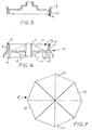
- Figure 3 illustrates more clearly how the pole 2 is offset from the centre of the base structure, extending through the base structure and to one side of a bottle 6 of propane gas which is held in a compartment therein.
- a supply conduit 7 is led up the pole from the bottle 6 to the gas burner 3 in a known manner.
- the offset positioning of the pole 2 is advantageous because it allows the top section 8 of the base to present a useful surface area 9 which may be adapted as a small table or tray surface.
- the top section 8 may be moulded in plastics material, and is non-load-bearing.
- the bottom section 10 of the base 1 may also be moulded in plastics material.
- a tubular part 11 houses the pole 2 and bears sideways loading stresses by means of top gussets 12 and bottom gussets 13.
- a metal plate with a hole to accommodate the pole, may be bolted to the underside of the bottom section 10, if required.
- a compartment 14 is formed by walls 15 into which ballast in the form of sand or concrete is placed by the user, for safety reasons and for supporting the pole.
- Five ground-engaging legs 16 support the entire structure, but a ground-engaging jockey wheel 17 may also be provided, for moving the heater when tipped to one side, to disengage the legs 16.
- the offset positioning of the pole does not substantially affect the centre of gravity or stability of the gas parasol heater, as compared with currently available models.
- the cylindrical side wall 18 of the base may be made of flexible plastics sheeting or thin flexible metal, such as aluminium sheeting, seated in a groove 19 in the bottom section 10 of the base.
- the top section 8 of the base has depending side walls 20, with a corresponding groove 21 for housing the wall 18. (see Figure 5)
- the lightweight wall 18 may be made in two half sections, one of Figure 5)
- the lightweight wall 18 may be made in two half sections, one of which is adapted as a sliding door in an appropriate groove, allowing easy access to the bottle 6 of gas.
- the bottle of gas is seated on a base plate 22 of metal, which includes a hole through which the pole 2 may pass, and is adapted to sit on top of the bottom section 10 of the base (see Figure 4).
- the deflector dish 4 or parasol is also shown in Figure 7.
- This is made in at least two, and preferably four identical sections 23, which have flanges 24 on the inside (see Figure 3) by which the sections 23 may be secured together, for example by screws.
- the dish may be of relatively large diameter, for example greater than one metre, and preferably about 1.2 metres, but easily broken down into four parts for packing and shipping.
- the outer circumferential flange 25 forms a small skirt, which may be scalloped or otherwise provided with a decorative finish (not shown).
- a larger diameter, and deeper, dish it will readily be appreciated that the heat output which is deflected downwardly is greatly increased.
- plastics and lightweight components in the alternative embodiment described above for the base structure means that the components of the base may be manufactured at substantially lower unit cost, making the unit more affordable to the home user. Also, the use of lightweight components, and components which may easily be packed into a single box measuring approximately 1 metre by 0.3 metres by 0.15 metres is possible, which makes the unit more manageable for shipping purposes, storage by the retailer and purchase by a home user. The parts are easy to assemble and the whole unit may be disassembled if desired.
- Figure 8 illustrates another embodiment of the invention, not limited to a gas parasol heater with an offset pole of lightweight construction as described with reference to Figures 3 to 7 above, but also to heaters with a central pole of standard, heavier, construction, as shown in Figures 1 and 2.
- a larger, extended table 30 extending over the edge of the base structure may be moulded in plastics as part of the base structure or as a separate table top which rests on top of the base structure, made in plastics or metal.
- the table top is preferably split in sections prior to assembly, for instance into two clip together sections.
- multiple curved dish sections are provided which may be attached together, or may already be attached at the apex and adapted to be folded or fanned out to form a rigid dish structure in a dome shape.
Landscapes
- Engineering & Computer Science (AREA)
- Chemical & Material Sciences (AREA)
- Combustion & Propulsion (AREA)
- Mechanical Engineering (AREA)
- General Engineering & Computer Science (AREA)
- Cookers (AREA)
- Holders For Apparel And Elements Relating To Apparel (AREA)
- Housings, Intake/Discharge, And Installation Of Fluid Heaters (AREA)
- Resistance Heating (AREA)
Abstract
Description
Claims (6)
- A gas parasol heating appliance comprising a base structure (51) for housing a bottle of gas, a pole (52) supportable on the base structure so as to extend upwardly from the base structure, a gas burner arrangement (53) connectable to and supportable on the pole (52) and a dish deflector (54) supportable above the gas burner arrangement and adapted to direct heat downwardly, the dish deflector comprising multiple dish sections (73, 82) characterised in that the dish sections have flanges and are separate and engageable and are adapted to be fastened together by means of the flanges, in use, so as to form the dish, the dish deflector can be in parts prior to packing and shipping, and can be assembled by a purchaser so as to form the dish.
- A heating appliance according to claim 1, comprising two to four separate dish sections.
- A heating appliance according to any one of claims 1 to 2, wherein the diameter of the assembled dish (54) is greater than one metre.
- A heating appliance to any one of the preceding claims wherein the diameter of the assembled dish (54) is about 1.1 to 1.2 metres.
- A heating appliance according to any one of claims 1 to 4 in which the top (58,8) of the base structure (51, 1) is provided with or is adapted so as to include an outer table or tray surface (59,9).
- A heating appliance according to claim 8, comprising in addition, an extended table surface (30) adapted to rest upon the said top (58,8) of the base structure (59,9).
Applications Claiming Priority (2)
| Application Number | Priority Date | Filing Date | Title |
|---|---|---|---|
| IE980646 | 1998-07-31 | ||
| IE980646A IES980646A2 (en) | 1998-07-31 | 1998-07-31 | A parasol space heater |
Publications (2)
| Publication Number | Publication Date |
|---|---|
| EP0976979A1 EP0976979A1 (en) | 2000-02-02 |
| EP0976979B1 true EP0976979B1 (en) | 2002-11-13 |
Family
ID=11041868
Family Applications (1)
| Application Number | Title | Priority Date | Filing Date |
|---|---|---|---|
| EP99202172A Expired - Lifetime EP0976979B1 (en) | 1998-07-31 | 1999-07-03 | A parasol space heater |
Country Status (5)
| Country | Link |
|---|---|
| EP (1) | EP0976979B1 (en) |
| AT (1) | ATE227824T1 (en) |
| DE (1) | DE69903892D1 (en) |
| ES (1) | ES2188090T3 (en) |
| IE (1) | IES980646A2 (en) |
Cited By (1)
| Publication number | Priority date | Publication date | Assignee | Title |
|---|---|---|---|---|
| WO2008112792A1 (en) * | 2007-03-12 | 2008-09-18 | Desa Ip, Llc | Gas light-post heater |
Families Citing this family (29)
| Publication number | Priority date | Publication date | Assignee | Title |
|---|---|---|---|---|
| FR2764677B1 (en) * | 1997-06-16 | 1999-09-03 | Jean Collet | TERRACE HEATING DEVICE |
| US6651647B2 (en) | 1998-09-18 | 2003-11-25 | Cpd Associates, Inc. | Heating apparatus with slidable shroud |
| US6102031A (en) * | 1998-09-18 | 2000-08-15 | Waters; Michael | Heating apparatus |
| US6422232B1 (en) * | 2000-05-26 | 2002-07-23 | The Coleman Company, Inc. | Heater with light |
| US6446623B1 (en) | 2000-09-15 | 2002-09-10 | Cfm-Rmc International, A Division Of The Vermont Castings Majestics Products Company | Miniature patio heater |
| NL1016220C2 (en) * | 2000-09-19 | 2002-03-21 | Jacobs Robertus Andreas A M | Parasol with heating device. |
| FR2814223A1 (en) * | 2000-09-21 | 2002-03-22 | Jean Collet | Heating appliance for use on terraces, e.g. in open-air restaurants or bars, has complementary lower heating element at base to ensure uniform heating |
| AU747519B1 (en) * | 2001-03-09 | 2002-05-16 | Tony John Archbold | Patio heater |
| US6745759B2 (en) | 2001-08-10 | 2004-06-08 | Cpd Associates, Inc. | Knock-down dome cover for a patio heater |
| US6550470B2 (en) * | 2001-09-26 | 2003-04-22 | Hsin-Lien Liang | Portable gas burner with detachable reflector and base |
| GB2381308A (en) * | 2001-10-23 | 2003-04-30 | J R Glenlomond Ltd | An electric patio light and heater apparatus |
| CA2466744C (en) | 2003-05-12 | 2012-03-13 | Caroline Duphily | Radiant heater deflector assembly |
| US7175424B2 (en) | 2003-06-24 | 2007-02-13 | Toby Frink | Indoor/outdoor patio heater fire sculpture |
| US7003217B2 (en) * | 2003-11-19 | 2006-02-21 | Hon Technology Inc. | Infrared heating system for patio umbrella |
| US7086396B2 (en) | 2004-02-11 | 2006-08-08 | Michael Waters | Heating apparatus |
| IES20050012A2 (en) * | 2005-01-17 | 2006-07-26 | James O'connell | Parasol heater |
| IES20050200A2 (en) * | 2005-04-06 | 2006-05-03 | James O Connell | Patio heater with fabric parasol |
| DK176070B1 (en) * | 2005-08-08 | 2006-03-20 | Carsten Frisgaard | Screen is for installation of existing reflector on terrace heater and reflects heat sideways, preventing heat from emerging where it is not required |
| WO2007025413A1 (en) * | 2005-09-01 | 2007-03-08 | Weidong Jin | A reflex cover for an outdoor heating stove |
| CA2631650A1 (en) | 2005-11-30 | 2007-06-07 | Ideen Aps | Combined sunshade and heater with light |
| AU312405S (en) | 2006-02-03 | 2007-01-16 | Pacific Trends Int Pty Ltd | Heater assembly and heater element therefor |
| GB2518814A (en) * | 2013-08-09 | 2015-04-08 | Ran Merkazy | Collapsible article |
| US20230009412A1 (en) * | 2021-07-09 | 2023-01-12 | Two Peaks, LLC | Portable fire table |
| USD1043933S1 (en) | 2021-11-12 | 2024-09-24 | Solo Brands, Llc | Device for fire pit |
| US11920798B2 (en) | 2021-11-12 | 2024-03-05 | Solo Brands, Llc | Heat deflector |
| GB2614290B (en) * | 2021-12-23 | 2023-12-20 | Stewart Oconnell | Parasol heater |
| EP4279834B1 (en) * | 2022-03-20 | 2026-02-04 | Hu, Xiaocun | Umbrella-shaped heater |
| USD1061856S1 (en) | 2023-03-30 | 2025-02-11 | Breeo, LLC | Heat deflector for fire pit |
| USD1059577S1 (en) | 2023-12-12 | 2025-01-28 | Breeo, LLC | Heat deflector for fire pit |
Citations (1)
| Publication number | Priority date | Publication date | Assignee | Title |
|---|---|---|---|---|
| JPH09196381A (en) * | 1996-01-19 | 1997-07-29 | Kaneda Kosakusho:Kk | Parasol type heater |
Family Cites Families (2)
| Publication number | Priority date | Publication date | Assignee | Title |
|---|---|---|---|---|
| FR2044254A5 (en) * | 1969-05-23 | 1971-02-19 | Anglade Jean | |
| FR2764677B1 (en) * | 1997-06-16 | 1999-09-03 | Jean Collet | TERRACE HEATING DEVICE |
-
1998
- 1998-07-31 IE IE980646A patent/IES980646A2/en not_active IP Right Cessation
-
1999
- 1999-07-03 EP EP99202172A patent/EP0976979B1/en not_active Expired - Lifetime
- 1999-07-03 ES ES99202172T patent/ES2188090T3/en not_active Expired - Lifetime
- 1999-07-03 AT AT99202172T patent/ATE227824T1/en not_active IP Right Cessation
- 1999-07-03 DE DE69903892T patent/DE69903892D1/en not_active Expired - Lifetime
Patent Citations (1)
| Publication number | Priority date | Publication date | Assignee | Title |
|---|---|---|---|---|
| JPH09196381A (en) * | 1996-01-19 | 1997-07-29 | Kaneda Kosakusho:Kk | Parasol type heater |
Cited By (1)
| Publication number | Priority date | Publication date | Assignee | Title |
|---|---|---|---|---|
| WO2008112792A1 (en) * | 2007-03-12 | 2008-09-18 | Desa Ip, Llc | Gas light-post heater |
Also Published As
| Publication number | Publication date |
|---|---|
| ES2188090T3 (en) | 2003-06-16 |
| IES80826B2 (en) | 1999-03-10 |
| EP0976979A1 (en) | 2000-02-02 |
| ATE227824T1 (en) | 2002-11-15 |
| IES980646A2 (en) | 1999-03-10 |
| DE69903892D1 (en) | 2002-12-19 |
Similar Documents
| Publication | Publication Date | Title |
|---|---|---|
| EP0976979A1 (en) | A parasol space heater | |
| US5354031A (en) | Low-profile umbrella base | |
| US6619281B2 (en) | Miniature patio heater | |
| US20250321007A1 (en) | Column heater with improved heat output | |
| US6446930B1 (en) | Umbrella base | |
| US9080751B2 (en) | Outdoor solar lamp with a base having flat and pointed foot elements | |
| US4693681A (en) | Candle apparatus | |
| US5743508A (en) | Tree stand with upward/extending support members forming part of a water basin | |
| US5158067A (en) | Wok adapted portable food cooker | |
| US4379587A (en) | Seat structure | |
| US6907875B1 (en) | Outdoor heater and method of assembling same | |
| US6637713B1 (en) | Log supporting apparatus | |
| US5641223A (en) | Horticulture lamp | |
| CA2486122A1 (en) | Infrared heating system for patio umbrella | |
| US7828002B2 (en) | Combined sunshade and heater with light | |
| US4954075A (en) | Lantern head for backpacker's stove | |
| US5347979A (en) | Chafing dish for outdoor use | |
| CN205878246U (en) | Stove effect equipment and be used for providing fiery external member on desktop | |
| CA2304086C (en) | Portable gas campfire | |
| US20020043181A1 (en) | Portable, personal table system | |
| US6302096B1 (en) | Stove, heater and lantern | |
| JP2829578B2 (en) | Parasol heating equipment | |
| US2532931A (en) | Combined christmas tree holder and tree watering pan | |
| US3103899A (en) | Tables of the cocktail or coffee type | |
| US20040241603A1 (en) | Multi-function candle accessory combining a venting chassis and candle holder |
Legal Events
| Date | Code | Title | Description |
|---|---|---|---|
| PUAI | Public reference made under article 153(3) epc to a published international application that has entered the european phase |
Free format text: ORIGINAL CODE: 0009012 |
|
| AK | Designated contracting states |
Kind code of ref document: A1 Designated state(s): AT BE CH CY DE DK ES FI FR GB GR IE IT LI LU MC NL PT SE |
|
| AX | Request for extension of the european patent |
Free format text: AL;LT;LV;MK;RO;SI |
|
| 17P | Request for examination filed |
Effective date: 20000327 |
|
| 17Q | First examination report despatched |
Effective date: 20000809 |
|
| AKX | Designation fees paid |
Free format text: AT BE CH CY DE DK ES FI FR GB GR IE IT LI LU MC NL PT SE |
|
| GRAG | Despatch of communication of intention to grant |
Free format text: ORIGINAL CODE: EPIDOS AGRA |
|
| GRAG | Despatch of communication of intention to grant |
Free format text: ORIGINAL CODE: EPIDOS AGRA |
|
| GRAG | Despatch of communication of intention to grant |
Free format text: ORIGINAL CODE: EPIDOS AGRA |
|
| GRAH | Despatch of communication of intention to grant a patent |
Free format text: ORIGINAL CODE: EPIDOS IGRA |
|
| GRAH | Despatch of communication of intention to grant a patent |
Free format text: ORIGINAL CODE: EPIDOS IGRA |
|
| GRAA | (expected) grant |
Free format text: ORIGINAL CODE: 0009210 |
|
| AK | Designated contracting states |
Kind code of ref document: B1 Designated state(s): AT BE CH CY DE DK ES FI FR GB GR IE IT LI LU MC NL PT SE |
|
| PG25 | Lapsed in a contracting state [announced via postgrant information from national office to epo] |
Ref country code: NL Free format text: LAPSE BECAUSE OF FAILURE TO SUBMIT A TRANSLATION OF THE DESCRIPTION OR TO PAY THE FEE WITHIN THE PRESCRIBED TIME-LIMIT Effective date: 20021113 Ref country code: LI Free format text: LAPSE BECAUSE OF FAILURE TO SUBMIT A TRANSLATION OF THE DESCRIPTION OR TO PAY THE FEE WITHIN THE PRESCRIBED TIME-LIMIT Effective date: 20021113 Ref country code: IT Free format text: LAPSE BECAUSE OF FAILURE TO SUBMIT A TRANSLATION OF THE DESCRIPTION OR TO PAY THE FEE WITHIN THE PRESCRIBED TIME-LIMIT;WARNING: LAPSES OF ITALIAN PATENTS WITH EFFECTIVE DATE BEFORE 2007 MAY HAVE OCCURRED AT ANY TIME BEFORE 2007. THE CORRECT EFFECTIVE DATE MAY BE DIFFERENT FROM THE ONE RECORDED. Effective date: 20021113 Ref country code: GR Free format text: LAPSE BECAUSE OF FAILURE TO SUBMIT A TRANSLATION OF THE DESCRIPTION OR TO PAY THE FEE WITHIN THE PRESCRIBED TIME-LIMIT Effective date: 20021113 Ref country code: FI Free format text: LAPSE BECAUSE OF FAILURE TO SUBMIT A TRANSLATION OF THE DESCRIPTION OR TO PAY THE FEE WITHIN THE PRESCRIBED TIME-LIMIT Effective date: 20021113 Ref country code: CH Free format text: LAPSE BECAUSE OF FAILURE TO SUBMIT A TRANSLATION OF THE DESCRIPTION OR TO PAY THE FEE WITHIN THE PRESCRIBED TIME-LIMIT Effective date: 20021113 Ref country code: BE Free format text: LAPSE BECAUSE OF FAILURE TO SUBMIT A TRANSLATION OF THE DESCRIPTION OR TO PAY THE FEE WITHIN THE PRESCRIBED TIME-LIMIT Effective date: 20021113 Ref country code: AT Free format text: LAPSE BECAUSE OF FAILURE TO SUBMIT A TRANSLATION OF THE DESCRIPTION OR TO PAY THE FEE WITHIN THE PRESCRIBED TIME-LIMIT Effective date: 20021113 |
|
| REF | Corresponds to: |
Ref document number: 227824 Country of ref document: AT Date of ref document: 20021115 Kind code of ref document: T |
|
| REG | Reference to a national code |
Ref country code: GB Ref legal event code: FG4D |
|
| REG | Reference to a national code |
Ref country code: CH Ref legal event code: EP |
|
| REG | Reference to a national code |
Ref country code: IE Ref legal event code: FG4D |
|
| REF | Corresponds to: |
Ref document number: 69903892 Country of ref document: DE Date of ref document: 20021219 |
|
| PG25 | Lapsed in a contracting state [announced via postgrant information from national office to epo] |
Ref country code: SE Free format text: LAPSE BECAUSE OF FAILURE TO SUBMIT A TRANSLATION OF THE DESCRIPTION OR TO PAY THE FEE WITHIN THE PRESCRIBED TIME-LIMIT Effective date: 20030213 Ref country code: PT Free format text: LAPSE BECAUSE OF FAILURE TO SUBMIT A TRANSLATION OF THE DESCRIPTION OR TO PAY THE FEE WITHIN THE PRESCRIBED TIME-LIMIT Effective date: 20030213 Ref country code: DK Free format text: LAPSE BECAUSE OF FAILURE TO SUBMIT A TRANSLATION OF THE DESCRIPTION OR TO PAY THE FEE WITHIN THE PRESCRIBED TIME-LIMIT Effective date: 20030213 |
|
| PG25 | Lapsed in a contracting state [announced via postgrant information from national office to epo] |
Ref country code: DE Free format text: LAPSE BECAUSE OF FAILURE TO SUBMIT A TRANSLATION OF THE DESCRIPTION OR TO PAY THE FEE WITHIN THE PRESCRIBED TIME-LIMIT Effective date: 20030214 |
|
| NLV1 | Nl: lapsed or annulled due to failure to fulfill the requirements of art. 29p and 29m of the patents act | ||
| REG | Reference to a national code |
Ref country code: CH Ref legal event code: PL |
|
| REG | Reference to a national code |
Ref country code: ES Ref legal event code: FG2A Ref document number: 2188090 Country of ref document: ES Kind code of ref document: T3 |
|
| PG25 | Lapsed in a contracting state [announced via postgrant information from national office to epo] |
Ref country code: LU Free format text: LAPSE BECAUSE OF NON-PAYMENT OF DUE FEES Effective date: 20030703 Ref country code: CY Free format text: LAPSE BECAUSE OF FAILURE TO SUBMIT A TRANSLATION OF THE DESCRIPTION OR TO PAY THE FEE WITHIN THE PRESCRIBED TIME-LIMIT Effective date: 20030703 |
|
| ET | Fr: translation filed | ||
| PG25 | Lapsed in a contracting state [announced via postgrant information from national office to epo] |
Ref country code: MC Free format text: LAPSE BECAUSE OF NON-PAYMENT OF DUE FEES Effective date: 20030731 |
|
| PLBQ | Unpublished change to opponent data |
Free format text: ORIGINAL CODE: EPIDOS OPPO |
|
| PLBI | Opposition filed |
Free format text: ORIGINAL CODE: 0009260 |
|
| PLAX | Notice of opposition and request to file observation + time limit sent |
Free format text: ORIGINAL CODE: EPIDOSNOBS2 |
|
| PLAZ | Examination of admissibility of opposition: despatch of communication + time limit |
Free format text: ORIGINAL CODE: EPIDOSNOPE2 |
|
| PLBA | Examination of admissibility of opposition: reply received |
Free format text: ORIGINAL CODE: EPIDOSNOPE4 |
|
| 26 | Opposition filed |
Opponent name: OUTBACK UK LIMITED Effective date: 20030808 |
|
| PLAX | Notice of opposition and request to file observation + time limit sent |
Free format text: ORIGINAL CODE: EPIDOSNOBS2 |
|
| PLBB | Reply of patent proprietor to notice(s) of opposition received |
Free format text: ORIGINAL CODE: EPIDOSNOBS3 |
|
| PLAB | Opposition data, opponent's data or that of the opponent's representative modified |
Free format text: ORIGINAL CODE: 0009299OPPO |
|
| PLAZ | Examination of admissibility of opposition: despatch of communication + time limit |
Free format text: ORIGINAL CODE: EPIDOSNOPE2 |
|
| PLBA | Examination of admissibility of opposition: reply received |
Free format text: ORIGINAL CODE: EPIDOSNOPE4 |
|
| PLBP | Opposition withdrawn |
Free format text: ORIGINAL CODE: 0009264 |
|
| PLBQ | Unpublished change to opponent data |
Free format text: ORIGINAL CODE: EPIDOS OPPO |
|
| PLCK | Communication despatched that opposition was rejected |
Free format text: ORIGINAL CODE: EPIDOSNREJ1 |
|
| REG | Reference to a national code |
Ref country code: GB Ref legal event code: 732E |
|
| PLBN | Opposition rejected |
Free format text: ORIGINAL CODE: 0009273 |
|
| STAA | Information on the status of an ep patent application or granted ep patent |
Free format text: STATUS: OPPOSITION REJECTED |
|
| 27O | Opposition rejected |
Effective date: 20050407 |
|
| PGFP | Annual fee paid to national office [announced via postgrant information from national office to epo] |
Ref country code: ES Payment date: 20061212 Year of fee payment: 8 |
|
| PGFP | Annual fee paid to national office [announced via postgrant information from national office to epo] |
Ref country code: FR Payment date: 20061218 Year of fee payment: 8 |
|
| REG | Reference to a national code |
Ref country code: FR Ref legal event code: ST Effective date: 20080331 |
|
| PG25 | Lapsed in a contracting state [announced via postgrant information from national office to epo] |
Ref country code: FR Free format text: LAPSE BECAUSE OF NON-PAYMENT OF DUE FEES Effective date: 20070731 |
|
| REG | Reference to a national code |
Ref country code: ES Ref legal event code: FD2A Effective date: 20070704 |
|
| PG25 | Lapsed in a contracting state [announced via postgrant information from national office to epo] |
Ref country code: ES Free format text: LAPSE BECAUSE OF NON-PAYMENT OF DUE FEES Effective date: 20070704 |
|
| PGFP | Annual fee paid to national office [announced via postgrant information from national office to epo] |
Ref country code: IE Payment date: 20100624 Year of fee payment: 12 |
|
| REG | Reference to a national code |
Ref country code: IE Ref legal event code: MM4A |
|
| PG25 | Lapsed in a contracting state [announced via postgrant information from national office to epo] |
Ref country code: IE Free format text: LAPSE BECAUSE OF NON-PAYMENT OF DUE FEES Effective date: 20110703 |
|
| PGFP | Annual fee paid to national office [announced via postgrant information from national office to epo] |
Ref country code: GB Payment date: 20180730 Year of fee payment: 20 |
|
| REG | Reference to a national code |
Ref country code: GB Ref legal event code: PE20 Expiry date: 20190702 |
|
| PG25 | Lapsed in a contracting state [announced via postgrant information from national office to epo] |
Ref country code: GB Free format text: LAPSE BECAUSE OF EXPIRATION OF PROTECTION Effective date: 20190702 |