EP0976617A1 - Support body for motor-vehicle numberplate lightning lamps - Google Patents
Support body for motor-vehicle numberplate lightning lamps Download PDFInfo
- Publication number
- EP0976617A1 EP0976617A1 EP99111189A EP99111189A EP0976617A1 EP 0976617 A1 EP0976617 A1 EP 0976617A1 EP 99111189 A EP99111189 A EP 99111189A EP 99111189 A EP99111189 A EP 99111189A EP 0976617 A1 EP0976617 A1 EP 0976617A1
- Authority
- EP
- European Patent Office
- Prior art keywords
- support body
- vehicle
- body according
- numberplate
- electric
- Prior art date
- Legal status (The legal status is an assumption and is not a legal conclusion. Google has not performed a legal analysis and makes no representation as to the accuracy of the status listed.)
- Granted
Links
Images
Classifications
-
- B—PERFORMING OPERATIONS; TRANSPORTING
- B60—VEHICLES IN GENERAL
- B60Q—ARRANGEMENT OF SIGNALLING OR LIGHTING DEVICES, THE MOUNTING OR SUPPORTING THEREOF OR CIRCUITS THEREFOR, FOR VEHICLES IN GENERAL
- B60Q1/00—Arrangement of optical signalling or lighting devices, the mounting or supporting thereof or circuits therefor
- B60Q1/26—Arrangement of optical signalling or lighting devices, the mounting or supporting thereof or circuits therefor the devices being primarily intended to indicate the vehicle, or parts thereof, or to give signals, to other traffic
- B60Q1/56—Arrangement of optical signalling or lighting devices, the mounting or supporting thereof or circuits therefor the devices being primarily intended to indicate the vehicle, or parts thereof, or to give signals, to other traffic for illuminating registrations or the like, e.g. for licence plates
-
- B—PERFORMING OPERATIONS; TRANSPORTING
- B60—VEHICLES IN GENERAL
- B60R—VEHICLES, VEHICLE FITTINGS, OR VEHICLE PARTS, NOT OTHERWISE PROVIDED FOR
- B60R13/00—Elements for body-finishing, identifying, or decorating; Arrangements or adaptations for advertising purposes
- B60R13/10—Registration, licensing, or like devices
Definitions
- the present invention refers to a support body for lamps used as lighting means for the numberplate of motor-vehicles, in particular motor-cars.
- Numberplates situated on the rear of motor-cars are generally known to be able to be illuminated by means of one or more lamps that are preferably mounted on at least a support body attached to the bodywork of the vehicle.
- the practice is known in the art to use an elongated support body that is fixed to the rear boot of the vehicle and is capable of supporting, further to the numberplate lighting lamps, also a manually actuatable device, preferably of the electromechanical type, for opening the same boot. More precisely, a manually operated level is provided which is adapted to actuate a switch that in turn energizes an electric motor, or similar means, in order to release the boot lock.
- the electrical connections of the lamps, as well as the possibly provided boot opening device are made in the form of wire harnesses that are housed in the support body and connected to the power supply source of the vehicle through a single loosable common connector fixed to the same support body.
- the harnessing of the electric wires in the support body undesirably complicates the fabrication thereof on an industrial scale and may also involve connection errors, ie. misconnections, considering that the wires themselves have to be eventually soldered to the terminals of corresponding lamp holders and the common connector.
- a purpose of the present invention is to provide a support body of the above cited kind, which does not require any soldering of the electric connectors.
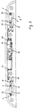
- the support body 4 may for instance have an elongated shape and is adapted to be fixed to the bodywork of a motor-vehicle, in a per sè known and not illustrated manner, preferably in correspondence of the rear boot of the same vehicle, in a position that is appropriately adjacent to the numberplate.
- the body 4 supports at least a lamp 5, preferably of the bulb type, adapted to light up the numberplate (not shown) of the vehicle and mounted in a removable manner by means of a pair of terminals 6, 7 that are adapted to also provide the electric contact thereof.
- a lamp 5 preferably of the bulb type, adapted to light up the numberplate (not shown) of the vehicle and mounted in a removable manner by means of a pair of terminals 6, 7 that are adapted to also provide the electric contact thereof.
- Two lamps 5 are illustrated in Figure 1 to be associated to respective pairs of contacts 6, 7.
- Respective electric conductors which are capable of being in a per sè known manner connected to the power supply source of the vehicle via respective contacts 8, 9 of at least a loosable connector 10, extend from said terminals 6, 7 in correspondence of the body 4.
- said electric conductors comprise a pair of appropriately shaped metal tracks 11, 12 attached to the support body 4.
- said metal tracks 11, 12 are made in the form of respective thin stainless-steel strips, or the like, that are appropriately bent and shaped in accordance with the conformation of the body 4, as shown in Figure 1.
- the vehicle is also provided with a manually actuatable electro-mechanical device for opening the boot of the vehicle.
- the body 4 carries also, again in a per sè known and non illustrated manner, a manually operated lever adapted to actuate a switch 14 which in turn is adapted to energize an electric motor, or the like, in order to unlatch or release the lock of the boot.
- the electric switch 14 is fixed to the body 4 and is provided with electric terminals 15, 16 that are connected by means of loosable coupling means 17 to respective tab-shaped portions 18, 19 of the metal track 11 and at least a further metal track 20, respectively.
- a further metal track 20 is made of thin stainless-steel strip, or similar material, and is adapted to be appropriately connected to the power supply source of the vehicle through a further contact 21 of the loosable connector 10.
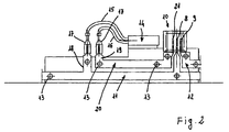
- the terminals 6, 7 are preferably constituted by respective elastic portions (shaped so as to form corresponding seats adapted to retain the lamp 5) of the thin metal strips 11, 12. In contrast with traditional solutions, therefore, no electric welding or soldering is needed here to conned the metal strips to special support means to be provided for the lamp 5, whose mechanical assembly and the related electric connection are ensured directly by said portions 6, 7 provided integrally with the metal strips 11, 12.
- the metal strips 11, 12 , 20 are preferably provided with a plurality of perforations 13, or the like, through which they can therefore be advantageously attached to corresponding fastening and locating pegs provided integrally on the body 4 which is preferably made of plastic material.
- said pegs can be inserted in the perforations 13 and be then hot-deformed by upsetting, or the like, in order to fasten the metal tracks 11, 12 in place.
- the pegs can be replaced with corresponding elastic teeth adapted to snap-fit into the perforations 13 so as to fasten the tracks 11, 12.
- said pegs or teeth constitute respective assembly locators that enable the same tracks to be correctly positioned and connected.
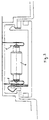
- the contacts 8, 9 and 21 of the loosable connector 10 are preferably constituted by respective portions of the metal tracks 11, 12, 20, so that no electric welding or soldering is needed for the connection of the same metal tracks to the power supply source of the vehicle either.
- the particularly simple manner in which the whole support body according to the present invention is capable of being assembled can therefore be readily appreciated along with the fact that a possibly required replacement of the switch 14 can furthermore be carried out by simply disconnecting its terminals by means of the afore cited loosable coupling means 17.
Abstract
Description
- The present invention refers to a support body for lamps used as lighting means for the numberplate of motor-vehicles, in particular motor-cars.
- Numberplates situated on the rear of motor-cars are generally known to be able to be illuminated by means of one or more lamps that are preferably mounted on at least a support body attached to the bodywork of the vehicle.
- In particular, the practice is known in the art to use an elongated support body that is fixed to the rear boot of the vehicle and is capable of supporting, further to the numberplate lighting lamps, also a manually actuatable device, preferably of the electromechanical type, for opening the same boot. More precisely, a manually operated level is provided which is adapted to actuate a switch that in turn energizes an electric motor, or similar means, in order to release the boot lock.
- In any case, the electrical connections of the lamps, as well as the possibly provided boot opening device, are made in the form of wire harnesses that are housed in the support body and connected to the power supply source of the vehicle through a single loosable common connector fixed to the same support body.
- The harnessing of the electric wires in the support body undesirably complicates the fabrication thereof on an industrial scale and may also involve connection errors, ie. misconnections, considering that the wires themselves have to be eventually soldered to the terminals of corresponding lamp holders and the common connector.
- Furthermore, should the boot opening device have to be replaced for any reason whatsoever, the need arises for the same wires to be cut and then, upon said device having been replaced, re-connected by means of appropriate connectors. Such an operation is largely known to prove undesirably complicated and expensive.
- It therefore is a purpose of the present invention to provide a support body for numberplate lighting lamps of motor-vehicles, which has a structure that is not only very simple, but also capable of being assembled and installed without any risk of errors.
- In particular, a purpose of the present invention is to provide a support body of the above cited kind, which does not require any soldering of the electric connectors.
- According to the present invention, these and further aims are reached in a support body for motor-vehicle numberplate lighting lamps which embodies the features recited in the appended claims.
- Characteristics and advantages of the present invention will anyway be more readily understood from the description that is given below by way of non-limiting example with reference to the accompanying drawings, in which
- Figure 1 is a schematical bottom view of a preferred embodiment of the support body according to the present invention;
- Figure 2 is a schematical, enlarged front view of a first detail of the support body illustrated in Figure 1; and
- Figure 3 is a schematical view on an enlarged scale of another detail of the support body illustrated in Figure 1.
- With reference to the Figures, the
support body 4 may for instance have an elongated shape and is adapted to be fixed to the bodywork of a motor-vehicle, in a per sè known and not illustrated manner, preferably in correspondence of the rear boot of the same vehicle, in a position that is appropriately adjacent to the numberplate. - The
body 4 supports at least alamp 5, preferably of the bulb type, adapted to light up the numberplate (not shown) of the vehicle and mounted in a removable manner by means of a pair ofterminals lamps 5 are illustrated in Figure 1 to be associated to respective pairs ofcontacts - Respective electric conductors, which are capable of being in a per sè known manner connected to the power supply source of the vehicle via
respective contacts loosable connector 10, extend fromsaid terminals body 4. - According to a feature of the present invention, said electric conductors comprise a pair of appropriately shaped
metal tracks 11, 12 attached to thesupport body 4. In a preferred manner, saidmetal tracks 11, 12 are made in the form of respective thin stainless-steel strips, or the like, that are appropriately bent and shaped in accordance with the conformation of thebody 4, as shown in Figure 1. - In a preferred manner, the vehicle is also provided with a manually actuatable electro-mechanical device for opening the boot of the vehicle. In this case, the
body 4 carries also, again in a per sè known and non illustrated manner, a manually operated lever adapted to actuate aswitch 14 which in turn is adapted to energize an electric motor, or the like, in order to unlatch or release the lock of the boot. - The
electric switch 14 is fixed to thebody 4 and is provided withelectric terminals 15, 16 that are connected by means of loosable coupling means 17 to respective tab-shaped portions further metal track 20, respectively. In a preferred manner, also such afurther metal track 20 is made of thin stainless-steel strip, or similar material, and is adapted to be appropriately connected to the power supply source of the vehicle through a further contact 21 of theloosable connector 10. - The
terminals thin metal strips 11, 12. In contrast with traditional solutions, therefore, no electric welding or soldering is needed here to conned the metal strips to special support means to be provided for thelamp 5, whose mechanical assembly and the related electric connection are ensured directly bysaid portions metal strips 11, 12. - The
metal strips perforations 13, or the like, through which they can therefore be advantageously attached to corresponding fastening and locating pegs provided integrally on thebody 4 which is preferably made of plastic material. For instance, said pegs can be inserted in theperforations 13 and be then hot-deformed by upsetting, or the like, in order to fasten themetal tracks 11, 12 in place. - As an alternative thereto, the pegs can be replaced with corresponding elastic teeth adapted to snap-fit into the
perforations 13 so as to fasten thetracks 11, 12. - In any case, for the
perforations 13, and therefore for all saidtracks - The
contacts loosable connector 10 are preferably constituted by respective portions of themetal tracks switch 14 can furthermore be carried out by simply disconnecting its terminals by means of the afore cited loosable coupling means 17. - In any case, fully apparent is the assembly and construction simplicity of all electric connections of the
support body 4, with the practical advantage of a corresponding time saving and cost cutting effect when manufacturing such a body on an industrial scale. - It will be also appreciated that a number of modifications can be introduced and made in the above described support body without departing from the scope of the present invention.
Claims (7)
- Support body for at least a lamp used to illuminate the numberplate of a motor-vehicle, comprising electric-contact and support terminals for said lamp that are capable of being connected to the power supply source of the vehicle by means of respective conductors, characterized in that said conductors comprise a pair of shaped metal tracks (11, 12) attached to the support body (4).
- Support body according to claim 1, in which at least a manually operated electric switch provided with electric terminals capable of being connected to the power supply source of the vehicle is fixed on to the same body, characterized in that the terminals (15, 16) of the electric switch (14) are connected by means of loosable coupling means (17) to respective tab-shaped portions (18, 19) of one of said metal tracks (11) and at least a further metal track (20) attached to the support body (4).
- Support body according to claim 1 or 2, characterized in that said metal tracks (11, 12; 20) are provided in the form of respective thin metal strips.
- Support body according to claim 3, characterized in that said terminals (6, 7) are constituted by respective elastic and appropriately shaped portions of said pair of metal strips (11, 12) that are capable of ensuring both the mechanical support and the electric connection of said numberplate lighting lamp (5).
- Support body according to claim 3, characterized in that said metal strips (11, 12; 20) comprise perforations (13), or the like, adapted to be fastened by deformation on to corresponding locating and attachment pegs provided on the support body (4).
- Support body according to claim 3, characterized in that said metal strips (11, 12; 20) comprise perforations (13), or the like, adapted to be snap-fitted on to corresponding elastic locating and attachment teeth provided on the support body (4).
- Support body according to claim 1 or 2, in which said conductors are capable of being connected to the power supply source of the vehicle through at least a loosable connector provided with respective contacts, characterized in that said contacts (8, 9, 21) of the loosable connector (10) are constituted by respective portions of said metal tracks (11, 12; 20).
Applications Claiming Priority (2)
| Application Number | Priority Date | Filing Date | Title |
|---|---|---|---|
| ITPN980040 | 1998-07-27 | ||
| ITPN980040 IT245321Y1 (en) | 1998-07-27 | 1998-07-27 | SUPPORT BODY FOR TARGADI VEHICLE LIGHTING LAMPS |
Publications (2)
| Publication Number | Publication Date |
|---|---|
| EP0976617A1 true EP0976617A1 (en) | 2000-02-02 |
| EP0976617B1 EP0976617B1 (en) | 2004-02-25 |
Family
ID=11395385
Family Applications (1)
| Application Number | Title | Priority Date | Filing Date |
|---|---|---|---|
| EP19990111189 Expired - Lifetime EP0976617B1 (en) | 1998-07-27 | 1999-06-09 | Support body for motor-vehicle numberplate lightning lamps |
Country Status (4)
| Country | Link |
|---|---|
| EP (1) | EP0976617B1 (en) |
| DE (1) | DE69914980T2 (en) |
| ES (1) | ES2217648T3 (en) |
| IT (1) | IT245321Y1 (en) |
Cited By (6)
| Publication number | Priority date | Publication date | Assignee | Title |
|---|---|---|---|---|
| FR2811277A1 (en) | 2000-07-06 | 2002-01-11 | Renault | Police sign panel lighting for motor vehicle boot lid has common support for switch and lamp with movable window for lamp connected to boot lid switch |
| WO2002006085A1 (en) | 2000-07-18 | 2002-01-24 | Plastal S.P.A | Support arrangement for lighting devices for the illumination of the number plate of motor-vehicles |
| EP1205360A1 (en) * | 2000-11-10 | 2002-05-15 | Volkswagen Aktiengesellschaft | Switching assembly for a self-illuminating number plate |
| EP1264732A2 (en) | 2001-06-08 | 2002-12-11 | Plastal S.p.A. | Lighting arrangement for the illumination of the number plate of motor-vehicles |
| GB2384104A (en) * | 2001-11-15 | 2003-07-16 | Plastal Spa | Support body for lighting devices for motor vehicle number plates |
| EP1299609B1 (en) | 2000-06-29 | 2017-11-08 | U-Shin France | Lock control assembly for a motor vehicle opening panel and opening panel equipped with same |
Families Citing this family (1)
| Publication number | Priority date | Publication date | Assignee | Title |
|---|---|---|---|---|
| CN105034938B (en) * | 2015-06-26 | 2017-05-10 | 奇瑞汽车股份有限公司 | License plate lamp shield for automobile |
Citations (5)
| Publication number | Priority date | Publication date | Assignee | Title |
|---|---|---|---|---|
| EP0079728A2 (en) * | 1981-11-13 | 1983-05-25 | Clearplas Limited | Illuminated mirror assembly |
| US4521838A (en) * | 1983-06-17 | 1985-06-04 | Youri Agabekov | Tubular electric lamp fixture |
| US5027262A (en) * | 1988-05-24 | 1991-06-25 | Lucifier Lighting Company | Flexible light rail |
| US5521799A (en) * | 1994-08-25 | 1996-05-28 | Verkamp; Kevin M. | Illuminated display assembly |
| DE19624789A1 (en) * | 1996-06-21 | 1998-01-08 | Hella Kg Hueck & Co | Roof-mountable sign for motor vehicle esp taxi |
-
1998
- 1998-07-27 IT ITPN980040 patent/IT245321Y1/en active
-
1999
- 1999-06-09 ES ES99111189T patent/ES2217648T3/en not_active Expired - Lifetime
- 1999-06-09 EP EP19990111189 patent/EP0976617B1/en not_active Expired - Lifetime
- 1999-06-09 DE DE1999614980 patent/DE69914980T2/en not_active Expired - Lifetime
Patent Citations (5)
| Publication number | Priority date | Publication date | Assignee | Title |
|---|---|---|---|---|
| EP0079728A2 (en) * | 1981-11-13 | 1983-05-25 | Clearplas Limited | Illuminated mirror assembly |
| US4521838A (en) * | 1983-06-17 | 1985-06-04 | Youri Agabekov | Tubular electric lamp fixture |
| US5027262A (en) * | 1988-05-24 | 1991-06-25 | Lucifier Lighting Company | Flexible light rail |
| US5521799A (en) * | 1994-08-25 | 1996-05-28 | Verkamp; Kevin M. | Illuminated display assembly |
| DE19624789A1 (en) * | 1996-06-21 | 1998-01-08 | Hella Kg Hueck & Co | Roof-mountable sign for motor vehicle esp taxi |
Cited By (8)
| Publication number | Priority date | Publication date | Assignee | Title |
|---|---|---|---|---|
| EP1299609B1 (en) | 2000-06-29 | 2017-11-08 | U-Shin France | Lock control assembly for a motor vehicle opening panel and opening panel equipped with same |
| EP1299609B2 (en) † | 2000-06-29 | 2023-09-27 | U-Shin France | Lock control assembly for a motor vehicle opening panel and opening panel equipped with same |
| FR2811277A1 (en) | 2000-07-06 | 2002-01-11 | Renault | Police sign panel lighting for motor vehicle boot lid has common support for switch and lamp with movable window for lamp connected to boot lid switch |
| WO2002006085A1 (en) | 2000-07-18 | 2002-01-24 | Plastal S.P.A | Support arrangement for lighting devices for the illumination of the number plate of motor-vehicles |
| EP1205360A1 (en) * | 2000-11-10 | 2002-05-15 | Volkswagen Aktiengesellschaft | Switching assembly for a self-illuminating number plate |
| EP1264732A2 (en) | 2001-06-08 | 2002-12-11 | Plastal S.p.A. | Lighting arrangement for the illumination of the number plate of motor-vehicles |
| GB2384104A (en) * | 2001-11-15 | 2003-07-16 | Plastal Spa | Support body for lighting devices for motor vehicle number plates |
| GB2384104B (en) * | 2001-11-15 | 2004-12-29 | Plastal Spa | Support body for lighting devices for motor vehicle licence plates |
Also Published As
| Publication number | Publication date |
|---|---|
| ITPN980040U1 (en) | 2000-01-27 |
| EP0976617B1 (en) | 2004-02-25 |
| DE69914980D1 (en) | 2004-04-01 |
| DE69914980T2 (en) | 2004-12-30 |
| ES2217648T3 (en) | 2004-11-01 |
| IT245321Y1 (en) | 2002-03-20 |
Similar Documents
| Publication | Publication Date | Title |
|---|---|---|
| JPH04230439A (en) | Room lamp combining detachable type flash light assembly | |
| CA2156564A1 (en) | Courtesy light fixture of the rearview mirror | |
| EP0744321A3 (en) | Modular rearview mirror assembly and method for making same | |
| EP0976617A1 (en) | Support body for motor-vehicle numberplate lightning lamps | |
| EP0265404B1 (en) | Sun visor with illuminated mirror | |
| US4178627A (en) | Lamp assembly | |
| JP4716698B2 (en) | Cigar lighter or multi-function electrical socket lighting device | |
| US4720132A (en) | Electrically conductive stiffening wire for a sun visor for vehicles | |
| US6276812B1 (en) | Electric lamp and lighting system for said lamp | |
| ATE262430T1 (en) | EXTERIOR REAR-VIEW MIRROR FOR A VEHICLE HAVING A LIGHTING DEVICE | |
| US20080225547A1 (en) | LED vehicle lamp | |
| US4213665A (en) | Electrical connector | |
| EP0449285A2 (en) | Illuminating device including a light emitting diode | |
| GB2053440A (en) | Vehicle light cluster | |
| US7128450B2 (en) | Modular light assembly and method for installing a modular light assembly in a vehicle | |
| US6315612B1 (en) | Carrier, primarily for light emitting diode | |
| JP3011206B1 (en) | Electrical connection device | |
| EP0344135B1 (en) | Sun visor and lighting installation for motor vehicles | |
| USRE28637E (en) | Vehicle lamp and terminal therefor | |
| GB2025162A (en) | Lamp holder | |
| KR200189199Y1 (en) | Rear combination lamp structure for vehicle | |
| KR200145130Y1 (en) | Motor with LED lamp for displaying electricity supply / operation status | |
| KR100412431B1 (en) | Lamp structure for vehicle license plate | |
| GB2242513B (en) | A ventilated illuminating or indicating appliance for an automotive vehicle,for example a headlamp or indicating lamp | |
| US1802392A (en) | Signal lamp |
Legal Events
| Date | Code | Title | Description |
|---|---|---|---|
| PUAI | Public reference made under article 153(3) epc to a published international application that has entered the european phase |
Free format text: ORIGINAL CODE: 0009012 |
|
| AK | Designated contracting states |
Kind code of ref document: A1 Designated state(s): DE ES FR GB IT PT SE |
|
| AX | Request for extension of the european patent |
Free format text: AL;LT;LV;MK;RO;SI |
|
| 17P | Request for examination filed |
Effective date: 20000613 |
|
| AKX | Designation fees paid |
Free format text: DE ES FR GB IT PT SE |
|
| RAP1 | Party data changed (applicant data changed or rights of an application transferred) |
Owner name: SAPA AUTOPLASTICS S.P.A. |
|
| RAP1 | Party data changed (applicant data changed or rights of an application transferred) |
Owner name: PLASTAL S.P.A. |
|
| 17Q | First examination report despatched |
Effective date: 20020515 |
|
| GRAP | Despatch of communication of intention to grant a patent |
Free format text: ORIGINAL CODE: EPIDOSNIGR1 |
|
| GRAS | Grant fee paid |
Free format text: ORIGINAL CODE: EPIDOSNIGR3 |
|
| GRAA | (expected) grant |
Free format text: ORIGINAL CODE: 0009210 |
|
| AK | Designated contracting states |
Kind code of ref document: B1 Designated state(s): DE ES FR GB IT PT SE |
|
| PG25 | Lapsed in a contracting state [announced via postgrant information from national office to epo] |
Ref country code: FR Free format text: LAPSE BECAUSE OF FAILURE TO SUBMIT A TRANSLATION OF THE DESCRIPTION OR TO PAY THE FEE WITHIN THE PRESCRIBED TIME-LIMIT Effective date: 20040225 |
|
| REG | Reference to a national code |
Ref country code: GB Ref legal event code: FG4D |
|
| REG | Reference to a national code |
Ref country code: SE Ref legal event code: TRGR |
|
| REF | Corresponds to: |
Ref document number: 69914980 Country of ref document: DE Date of ref document: 20040401 Kind code of ref document: P |
|
| REG | Reference to a national code |
Ref country code: ES Ref legal event code: FG2A Ref document number: 2217648 Country of ref document: ES Kind code of ref document: T3 |
|
| PLBE | No opposition filed within time limit |
Free format text: ORIGINAL CODE: 0009261 |
|
| STAA | Information on the status of an ep patent application or granted ep patent |
Free format text: STATUS: NO OPPOSITION FILED WITHIN TIME LIMIT |
|
| EN | Fr: translation not filed | ||
| 26N | No opposition filed |
Effective date: 20041126 |
|
| PG25 | Lapsed in a contracting state [announced via postgrant information from national office to epo] |
Ref country code: PT Free format text: LAPSE BECAUSE OF NON-PAYMENT OF DUE FEES Effective date: 20040725 |
|
| PGFP | Annual fee paid to national office [announced via postgrant information from national office to epo] |
Ref country code: ES Payment date: 20080605 Year of fee payment: 10 |
|
| PGFP | Annual fee paid to national office [announced via postgrant information from national office to epo] |
Ref country code: SE Payment date: 20080519 Year of fee payment: 10 |
|
| REG | Reference to a national code |
Ref country code: ES Ref legal event code: FD2A Effective date: 20090610 |
|
| PG25 | Lapsed in a contracting state [announced via postgrant information from national office to epo] |
Ref country code: ES Free format text: LAPSE BECAUSE OF NON-PAYMENT OF DUE FEES Effective date: 20090610 |
|
| PGFP | Annual fee paid to national office [announced via postgrant information from national office to epo] |
Ref country code: GB Payment date: 20100618 Year of fee payment: 12 Ref country code: DE Payment date: 20100625 Year of fee payment: 12 |
|
| PG25 | Lapsed in a contracting state [announced via postgrant information from national office to epo] |
Ref country code: SE Free format text: LAPSE BECAUSE OF NON-PAYMENT OF DUE FEES Effective date: 20090610 |
|
| GBPC | Gb: european patent ceased through non-payment of renewal fee |
Effective date: 20110609 |
|
| REG | Reference to a national code |
Ref country code: DE Ref legal event code: R119 Ref document number: 69914980 Country of ref document: DE Effective date: 20120103 |
|
| PG25 | Lapsed in a contracting state [announced via postgrant information from national office to epo] |
Ref country code: DE Free format text: LAPSE BECAUSE OF NON-PAYMENT OF DUE FEES Effective date: 20120103 |
|
| PG25 | Lapsed in a contracting state [announced via postgrant information from national office to epo] |
Ref country code: GB Free format text: LAPSE BECAUSE OF NON-PAYMENT OF DUE FEES Effective date: 20110609 |
|
| PG25 | Lapsed in a contracting state [announced via postgrant information from national office to epo] |
Ref country code: IT Free format text: LAPSE BECAUSE OF NON-PAYMENT OF DUE FEES Effective date: 20150609 |
|
| PGRI | Patent reinstated in contracting state [announced from national office to epo] |
Ref country code: IT Effective date: 20160412 |
|
| PGFP | Annual fee paid to national office [announced via postgrant information from national office to epo] |
Ref country code: IT Payment date: 20180618 Year of fee payment: 20 |