EP0976305B1 - Procede de traitement d'un signal audio - Google Patents
Procede de traitement d'un signal audio Download PDFInfo
- Publication number
- EP0976305B1 EP0976305B1 EP98960002A EP98960002A EP0976305B1 EP 0976305 B1 EP0976305 B1 EP 0976305B1 EP 98960002 A EP98960002 A EP 98960002A EP 98960002 A EP98960002 A EP 98960002A EP 0976305 B1 EP0976305 B1 EP 0976305B1
- Authority
- EP
- European Patent Office
- Prior art keywords
- sound source
- head
- audio signal
- distance
- listener
- Prior art date
- Legal status (The legal status is an assumption and is not a legal conclusion. Google has not performed a legal analysis and makes no representation as to the accuracy of the status listed.)
- Expired - Lifetime
Links
Images


Classifications
-
- H—ELECTRICITY
- H04—ELECTRIC COMMUNICATION TECHNIQUE
- H04S—STEREOPHONIC SYSTEMS
- H04S7/00—Indicating arrangements; Control arrangements, e.g. balance control
- H04S7/30—Control circuits for electronic adaptation of the sound field
- H04S7/302—Electronic adaptation of stereophonic sound system to listener position or orientation
-
- H—ELECTRICITY
- H04—ELECTRIC COMMUNICATION TECHNIQUE
- H04S—STEREOPHONIC SYSTEMS
- H04S5/00—Pseudo-stereo systems, e.g. in which additional channel signals are derived from monophonic signals by means of phase shifting, time delay or reverberation
-
- H—ELECTRICITY
- H04—ELECTRIC COMMUNICATION TECHNIQUE
- H04S—STEREOPHONIC SYSTEMS
- H04S2400/00—Details of stereophonic systems covered by H04S but not provided for in its groups
- H04S2400/01—Multi-channel, i.e. more than two input channels, sound reproduction with two speakers wherein the multi-channel information is substantially preserved
Definitions
- This invention relates to a method of processing a single channel audio signal to provide an audio signal having left and right channels corresponding to a sound source at a given direction in space relative to a preferred position of a listener in use, the information in the channels including cues for perception of the direction of said single channel audio signal from said preferred position, the method including the steps of: a) providing a two channel signal having the same single channel signal in the two channels; b) modifying the two channel signal by modifying each of the channels using one of a plurality of head response transfer functions to provide a right signal in one channel for the right ear of a listener and a left signal in the other channel for the left ear of the listener; and c) introducing a time delay between the channels corresponding to the inter-aural time difference for a signal coming from said given direction, the inter-aural time difference providing cues to perception of the direction of the sound source at a given time.
- the present invention relates particularly to the reproduction of 3D-sound from two-speaker stereo systems or headphones.
- a mono sound source can be digitally processed via a pair of "Head-Response Transfer Functions" (HRTFs), such that the resultant stereo-pair signal contains 3D-sound cues.
- HRTFs Head-Response Transfer Functions
- IAD inter-aural amplitude difference
- ITD inter-aural time difference
- spectral shaping by the outer ear.
- the loudspeaker in order to have the effects of these loudspeaker signals representative of a point source, the loudspeaker must be spaced at a distance of around 1 metre from the artificial head. Secondly, it is usually required to create sound effects for PC games and the like which possess apparent distances of several metres or greater, and so, because there is little difference between HRTFs measured at 1 metre and those measured at much greater distances, the 1 metre measurement is used.
- the effect of a sound source appearing to be in the mid-distance (1 to 5 m, say) or far-distance (>5 m) can be created easily by the addition of a reverberation signal to the primary signal, thus simulating the effects of reflected sound waves from the floor and walls of the environment.
- a reduction of the high frequency (HF) components of the sound source can also help create the effect of a distant source, simulating the selective absorption of HF by air, although this is a more subtle effect.
- HF high frequency
- the present invention comprises a means of creating near-field distance effects for 3D-sound synthesis using a "standard" 1 metre HRTF set.
- the method uses an algorithm which controls the relative left-right channel amplitude difference as a function of (a) required proximity, and (b) spatial position.
- the algorithm is based on the observation that when a sound source moves towards the head from a distance of 1 metre, then the individual left and right-ear properties of the HRTF do not change a great deal in terms of their spectral properties. However, their amplitudes, and the amplitude difference between them, do change substantially, caused by a distance ratio effect.
- the small changes in spectral properties which do occur are related largely to head-shadowing effects, and these can be incorporated into the near-field effect algorithm in addition if desired.
- the expression "near-field” is defined to mean that volume of space around the listener's head up to a distance of about 1 - 1.5 metre from the centre of the head.
- a “closeness limit” For practical reasons, it is also useful to define a "closeness limit", and a distance of 0.2 m has been chosen for the present purpose of illustrating the invention. These limits have both been chosen purely for descriptive purposes, based respectively upon a typical HRTF measurement distance (1 m) and the closest simulation distance one might wish to create, in a game, say. However, it is also important to note that the ultimate "closeness” is represented by the listener hearing the sound ONLY in a single ear, as would be the case if he or she were wearing a single earphone.
- the distance ratio (left-ear to sound source vs. right-ear to sound source) becomes greater.
- the intensity of a sound source diminishes with distance as the energy of the propagating wave is spread over an increasing area.
- the wavefront is similar to an expanding bubble, and the energy density is related to the surface area of the propagating wavefront, which is related by a square law to the distance travelled (the radius of the bubble).
- the intensity ratios of left and right channels are related to the inverse ratio of the squares of the distances.
- the intensity ratios for distances of 1 m, 0.5 m and 0.2 m are approximately 1.49, 2.25 and 16 respectively. In dB units, these ratios are 1.73 dB, 3.52 dB and 12.04 dB respectively.
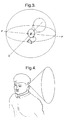
- Figure 1 shows a diagram of the near-field space around the listener, together with the reference planes and axes which will be referred to during the following descriptions, in which P-P' represents the front-back axis in the horizontal plane, intercepting the centre of the listener's head, and with Q-Q' representing the corresponding lateral axis from left to right.
- the path length is about 19.3 cm, and the associated ITD is about 563 ⁇ s.
- the ITDs are measured to be slightly larger than this, typically up to 702 ⁇ s. It is likely that this is caused by the non-spherical nature of the head (including the presence of the pinnae and nose), the complex diffractive situation and surface effects.
- the next stage is to find out a means of determining the value of the signal gains which must be applied to the left and right-ear channels when a "close" virtual sound source is required. This can be done if the near- and far-ear situations are considered in turn, and if we use the 1 metre distance as the outermost reference datum, at which point we define the sound intensity to be 0 dB.
- Figure 5 shows a plan view of the listener's head, together with the near-field area surrounding it.
- the situation is trivial to resolve, as shown in Figure 6 , if the "true" source-to-ear paths for the close frontal positions (such as path "A”) are assumed to be similar to the direct distance (indicated by "B").
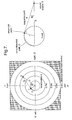
- Figure 7 shows a plan view of the listener's head, together with the near-field area surrounding it.
- the path between the sound source and the far-ear comprises two serial elements, as is shown clearly in the right hand detail of Figure 7 .
- the distance from the sound source to the centre of the head is d, and the head radius is r.
- the angle subtended by the tangent point and the head centre at the source is angle R.
- the angle P-head_centre-T is (90 - ⁇ - R), and so the angle T-head_centre-Q (the angle subtended by the arc itself) must be ( ⁇ + R).
- the 100 cm line is equal to 0 dB at azimuth 0°, as one expects, and as the sound source moves around to the 90° position, in line with the near-ear, the level increases to +0.68 dB, because the source is actually slightly closer.
- the 20 cm distance line shows a gain of 13.4 dB at azimuth 0°, because, naturally, it is closer, and, again, the level increases as the sound source moves around to the 90° position, to 18.1: a much greater increase this time.
- the other distance lines show intermediate properties between these two extremes.
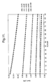
- the near-ear gain factor This is depicted graphically in Figure 11 .
- the 100 cm line is equal to 0 dB at azimuth 0° (as one expects), but here, as the sound source moves around to the 90 position, away from the far-ear, the level decreases to -0.99 dB.
- the 20 cm distance line shows a gain of 13.8 dB at azimuth 0°, similar to the equidistant near-ear, and, again, the level decreases as the sound source moves around to the 90 position, to 9.58: a much greater decrease than for the 100 cm data.
- the other distance lines show intermediate properties between these two extremes.
- each HRTF can be used as an index for selecting the appropriate L and R gain factors. Every inter-aural time-delay is associated with a horizontal plane equivalent, which, in turn, is associated with a specific azimuth angle. This means that a much smaller look-up table can be used.
- An HRTF library of the above resolution features horizontal plane increments of 3°, such that there are 31 HRTFs in the range 0° to 90°. Consequently, the size of a time-delay-indexed look-up table would be 31 x 4 x 2 elements (248 elements), which is only 2.8% the size of the "universal" table, above.
- the final stage in the description of the invention is to tabulate measured, horizontal-plane, HRTF time-delays in the range 0° to 90° against their azimuth angles, together with the near-ear and far-ear gain factors derived in previous sections. This links the time-delays to the gain factors, and represents the look-up table for use in a practical system. This data is shown below in the form of Table 1 (near-ear data) and Table 2 (far-ear data). Table 1 Time-delay based look-up table for determining near-ear gain factor as function of distance between virtual sound source and centre of the head.
- Figure 8 shows the conventional means of creating a virtual sound source, as follows.
- the HRTF comprises a left-ear function, a right-ear function and an inter-aural time-delay value.
- the HRTF data will generally be in the form of FIR filter coefficients suitable for controlling a pair of FIR filters (one for each channel), and the time-delay will be represented by a number.
- a monophonic sound source is then transmitted into the signal-processing scheme, as shown, thus creating both a left- and right-hand channel outputs. (These output signals are then suitable for onward transmission to the listener's headphones, or crosstalk-cancellation processing for loudspeaker reproduction, or other means).
- the invention shown in Figure 9 , supplements this procedure, but requires little extra computation.
- the signals are processed as previously, but a near-field distance is also specified, and, together with the time-delay data from the selected HRTF, is used to select the gain for respective left and right channels from a look-up table; this data is then used to control the gain of the signals before they are output to subsequent stages, as described before.
- the left channel output and the right channel output shown in Figure 9 can be combined directly with a normal stereo or binaural signal being fed to headphones, for example, simply by adding the signal in corresponding channels. If the outputs shown in Figure 9 are to be combined with those created for producing a 3D sound-field generated, for example, by binaural synthesis (such as, for example, using the Sensaura (Trade Mark) method described in EP-B-0689756 ), then the two output signals should be added to the corresponding channels of the binaural signal after transaural crosstalk compensation has been performed.
- binaural synthesis such as, for example, using the Sensaura (Trade Mark) method described in EP-B-0689756
- the magnitudes may be set before such signal processing if desired, so that the order of the steps in the described method is not an essential part of the invention.
- the position of the virtual sound source relative to the preferred position of a listener's head in use is constant and does not change with time, by suitable choice of sucessive different positions for the virtual sound source it can be made to move relative to the head of the listener in use if desired.
- This apparent movement may be provided by changing the direction of the virtual souce from the preferred position, by changing the distance to it, or by changing both together.
Abstract
Claims (14)
- Procédé de fourniture d'indices de localisation à un signal audio source pour percevoir une source sonore à une direction sélectionnée et une distance de champ proche sélectionnée depuis la tête d'un auditeur d'après une paire de fonctions de transfert relative à la tête (HRTF) déterminée pour la source sonore située à la direction sélectionnée et une distance de référence à une distance supérieure depuis la tâte de l'auditeur, le procédé comprenant :la production d'un signal audio à deux canaux depuis le signal audio source ;la mise en forme spectrale du signal audio à deux canaux d'après la paire HRTF ;l'introduction d'un retard temporel entre les canaux du signal audio à deux canaux basé sur un retard temporel interauriculaire associé à la direction sélectionnée ; etl'application d'un facteur de gain différent à chacun des deux canaux ;caractérisé en ce que les facteurs de gain différents sont déterminés en fonction de la direction sélectionnée et de la distance de champ proche sélectionnée depuis la tête de l'auditeur.
- Procédé selon la revendication 1, dans lequel les facteurs de gain différents sont déterminés pour chaque oreille d'après le carré inverse des distances respectives de la source sonore aux oreilles pour la source sonore positionnée à la distance de champ proche sélectionnée depuis la tête de l'auditeur.
- Procédé selon la revendication 2, dans lequel les facteurs de gain différents sont déterminés en fournissant une table de consultation de valeurs de gain indexées par le retard temporel interauriculaire associé à la direction sélectionnée et en sélectionnant les valeurs de gain respectives dans la table de consultation.
- Procédé selon la revendication 2, dans lequel les facteurs de gain différents sont déterminés en sélectionnant le retard temporel interauriculaire associé à la direction sélectionnée comme représentant la différence de longueurs de chemin entre la source sonore et les oreilles respectives, en déterminant un azimut dans le plan horizontal à partir du retard temporel interauriculaire, et en déterminant les distances respectives de la source sonore aux oreilles pour la source sonore positionnée à la distance de champ proche.
- Procédé selon l'une quelconque des revendications 1 à 4, dans lequel la distance de référence est d'environ 1m.
- Procédé selon la revendication 5, dans lequel la distance de champ proche est supérieure ou égale à 0,2 m et inférieure ou égale à environ 1,5 m.
- Procédé selon l'une quelconque des revendications précédentes, dans lequel l'application d'un facteur de gain différent se produit avant la mise en forme spectrale des signaux des canaux gauche et droit.
- Procédé selon l'une quelconque des revendications précédentes, dans lequel l'application d'un facteur de gain différent se produit après la mise en forme spectrale des signaux des canaux gauche et droit.
- Procédé selon l'une quelconque des revendications précédentes, comprenant en outre la modification de la réponse de fréquence de l'un des deux canaux afin de refléter les effets d'ombre de la tête à la distance de champ proche.
- Procédé selon l'une quelconque des revendications précédentes, dans lequel la paire HRTF est sélectionnée parmi une pluralité de paires HRTF correspondant respectivement à une pluralité de directions à la distance de référence.
- Procédé selon l'une quelconque des revendications précédentes, dans lequel le signal audio source doté d'indices de localisation est combiné à un autre signal audio à deux ou plusieurs canaux.
- Procédé selon la revendication 11, dans lequel les signaux sont combinés en ajoutant le contenu des canaux gauche et droit correspondants pour fournir un signal combiné ayant des canaux gauche et droit.
- Programme informatique, qui, lorsqu'il est chargé dans un ordinateur convenable, exécute un procédé selon l'une quelconque des revendications précédentes.
- Appareil pour exécuter un procédé selon la revendication 1, l'appareil comprenant : un moyen pour produire un signal audio à deux canaux depuis un signal audio source ; un moyen pour mettre en forme spectralement le signal audio à deux canaux d'après la paire HRTF ; un moyen pour introduire un retard temporel entre les canaux du signal audio à deux canaux basé sur un retard temporel interauriculaire associé à la direction sélectionnée ; et un moyen pour appliquer un facteur de gain différent à chacun des deux canaux ;
caractérisé en ce que les facteurs de gain différents sont déterminés en fonction de la direction sélectionnée et de la distance de champ proche sélectionnée depuis la tête de l'auditeur.
Applications Claiming Priority (3)
| Application Number | Priority Date | Filing Date | Title |
|---|---|---|---|
| GBGB9726338.8A GB9726338D0 (en) | 1997-12-13 | 1997-12-13 | A method of processing an audio signal |
| GB9726338 | 1997-12-13 | ||
| PCT/GB1998/003714 WO1999031938A1 (fr) | 1997-12-13 | 1998-12-11 | Procede de traitement d'un signal audio |
Publications (2)
| Publication Number | Publication Date |
|---|---|
| EP0976305A1 EP0976305A1 (fr) | 2000-02-02 |
| EP0976305B1 true EP0976305B1 (fr) | 2009-08-26 |
Family
ID=10823548
Family Applications (1)
| Application Number | Title | Priority Date | Filing Date |
|---|---|---|---|
| EP98960002A Expired - Lifetime EP0976305B1 (fr) | 1997-12-13 | 1998-12-11 | Procede de traitement d'un signal audio |
Country Status (6)
| Country | Link |
|---|---|
| US (1) | US7167567B1 (fr) |
| EP (1) | EP0976305B1 (fr) |
| JP (2) | JP4633870B2 (fr) |
| DE (1) | DE69841097D1 (fr) |
| GB (1) | GB9726338D0 (fr) |
| WO (1) | WO1999031938A1 (fr) |
Families Citing this family (55)
| Publication number | Priority date | Publication date | Assignee | Title |
|---|---|---|---|---|
| EP1410685A2 (fr) * | 1999-11-03 | 2004-04-21 | Boris Weigend | Systeme de traitement du son a canaux multiples |
| AUPQ514000A0 (en) | 2000-01-17 | 2000-02-10 | University Of Sydney, The | The generation of customised three dimensional sound effects for individuals |
| GB2369976A (en) * | 2000-12-06 | 2002-06-12 | Central Research Lab Ltd | A method of synthesising an averaged diffuse-field head-related transfer function |
| JP3435156B2 (ja) * | 2001-07-19 | 2003-08-11 | 松下電器産業株式会社 | 音像定位装置 |
| ATE426235T1 (de) | 2002-04-22 | 2009-04-15 | Koninkl Philips Electronics Nv | Dekodiervorrichtung mit dekorreliereinheit |
| FR2847376B1 (fr) * | 2002-11-19 | 2005-02-04 | France Telecom | Procede de traitement de donnees sonores et dispositif d'acquisition sonore mettant en oeuvre ce procede |
| US20060072764A1 (en) * | 2002-11-20 | 2006-04-06 | Koninklijke Philips Electronics N.V. | Audio based data representation apparatus and method |
| EP1667487A4 (fr) * | 2003-09-08 | 2010-07-14 | Panasonic Corp | Outil de conception de dispositif de commande d'images audio et dispositif associe |
| ATE502311T1 (de) * | 2003-10-10 | 2011-04-15 | Harman Becker Automotive Sys | System und verfahren zur bestimmung der position einer schallquelle |
| US6937737B2 (en) * | 2003-10-27 | 2005-08-30 | Britannia Investment Corporation | Multi-channel audio surround sound from front located loudspeakers |
| JP2005223713A (ja) * | 2004-02-06 | 2005-08-18 | Sony Corp | 音響再生装置、音響再生方法 |
| JP2005333621A (ja) * | 2004-04-21 | 2005-12-02 | Matsushita Electric Ind Co Ltd | 音情報出力装置及び音情報出力方法 |
| JP4103846B2 (ja) * | 2004-04-30 | 2008-06-18 | ソニー株式会社 | 情報処理装置、音量制御方法、記録媒体、およびプログラム |
| US8467552B2 (en) * | 2004-09-17 | 2013-06-18 | Lsi Corporation | Asymmetric HRTF/ITD storage for 3D sound positioning |
| US7634092B2 (en) * | 2004-10-14 | 2009-12-15 | Dolby Laboratories Licensing Corporation | Head related transfer functions for panned stereo audio content |
| US20060177073A1 (en) * | 2005-02-10 | 2006-08-10 | Isaac Emad S | Self-orienting audio system |
| US20060277034A1 (en) * | 2005-06-01 | 2006-12-07 | Ben Sferrazza | Method and system for processing HRTF data for 3-D sound positioning |
| KR100619082B1 (ko) * | 2005-07-20 | 2006-09-05 | 삼성전자주식회사 | 와이드 모노 사운드 재생 방법 및 시스템 |
| JP4602204B2 (ja) | 2005-08-31 | 2010-12-22 | ソニー株式会社 | 音声信号処理装置および音声信号処理方法 |
| WO2007045016A1 (fr) * | 2005-10-20 | 2007-04-26 | Personal Audio Pty Ltd | Simulation audio spatiale |
| JP4637725B2 (ja) | 2005-11-11 | 2011-02-23 | ソニー株式会社 | 音声信号処理装置、音声信号処理方法、プログラム |
| WO2007080211A1 (fr) * | 2006-01-09 | 2007-07-19 | Nokia Corporation | Methode de decodage de signaux audio binauraux |
| JP4944902B2 (ja) * | 2006-01-09 | 2012-06-06 | ノキア コーポレイション | バイノーラルオーディオ信号の復号制御 |
| WO2007080224A1 (fr) * | 2006-01-09 | 2007-07-19 | Nokia Corporation | Décodage de signaux audio binauraux |
| US7876904B2 (en) * | 2006-07-08 | 2011-01-25 | Nokia Corporation | Dynamic decoding of binaural audio signals |
| JP4894386B2 (ja) | 2006-07-21 | 2012-03-14 | ソニー株式会社 | 音声信号処理装置、音声信号処理方法および音声信号処理プログラム |
| JP4835298B2 (ja) | 2006-07-21 | 2011-12-14 | ソニー株式会社 | オーディオ信号処理装置、オーディオ信号処理方法およびプログラム |
| US8432834B2 (en) * | 2006-08-08 | 2013-04-30 | Cisco Technology, Inc. | System for disambiguating voice collisions |
| US8270616B2 (en) * | 2007-02-02 | 2012-09-18 | Logitech Europe S.A. | Virtual surround for headphones and earbuds headphone externalization system |
| JP5114981B2 (ja) * | 2007-03-15 | 2013-01-09 | 沖電気工業株式会社 | 音像定位処理装置、方法及びプログラム |
| US8682679B2 (en) | 2007-06-26 | 2014-03-25 | Koninklijke Philips N.V. | Binaural object-oriented audio decoder |
| KR101238361B1 (ko) * | 2007-10-15 | 2013-02-28 | 삼성전자주식회사 | 어레이 스피커 시스템에서 근접장 효과를 보상하는 방법 및장치 |
| US8520872B2 (en) * | 2008-08-14 | 2013-08-27 | Samsung Electronics Co., Ltd. | Apparatus and method for sound processing in a virtual reality system |
| US9247369B2 (en) * | 2008-10-06 | 2016-01-26 | Creative Technology Ltd | Method for enlarging a location with optimal three-dimensional audio perception |
| WO2010048157A1 (fr) | 2008-10-20 | 2010-04-29 | Genaudio, Inc. | Spatialisation audio et simulation d’environnement |
| EP2489207A4 (fr) * | 2009-10-12 | 2013-10-30 | Nokia Corp | Analyse multivoie pour traitement audio |
| CN102223589A (zh) * | 2010-04-14 | 2011-10-19 | 北京富纳特创新科技有限公司 | 投音机 |
| US9344813B2 (en) * | 2010-05-04 | 2016-05-17 | Sonova Ag | Methods for operating a hearing device as well as hearing devices |
| US9332372B2 (en) * | 2010-06-07 | 2016-05-03 | International Business Machines Corporation | Virtual spatial sound scape |
| DE102010030534A1 (de) * | 2010-06-25 | 2011-12-29 | Iosono Gmbh | Vorrichtung zum Veränderung einer Audio-Szene und Vorrichtung zum Erzeugen einer Richtungsfunktion |
| KR20120004909A (ko) | 2010-07-07 | 2012-01-13 | 삼성전자주식회사 | 입체 음향 재생 방법 및 장치 |
| KR101702330B1 (ko) * | 2010-07-13 | 2017-02-03 | 삼성전자주식회사 | 근거리 및 원거리 음장 동시제어 장치 및 방법 |
| WO2012011015A1 (fr) * | 2010-07-22 | 2012-01-26 | Koninklijke Philips Electronics N.V. | Système et procédé de reproduction de son |
| CH703771A2 (de) * | 2010-09-10 | 2012-03-15 | Stormingswiss Gmbh | Vorrichtung und Verfahren zur zeitlichen Auswertung und Optimierung von stereophonen oder pseudostereophonen Signalen. |
| US8660271B2 (en) | 2010-10-20 | 2014-02-25 | Dts Llc | Stereo image widening system |
| US9154897B2 (en) | 2011-01-04 | 2015-10-06 | Dts Llc | Immersive audio rendering system |
| JP5437317B2 (ja) * | 2011-06-10 | 2014-03-12 | 株式会社スクウェア・エニックス | ゲーム音場生成装置 |
| EP2974384B1 (fr) | 2013-03-12 | 2017-08-30 | Dolby Laboratories Licensing Corporation | Procédé de restitution d'un ou plusieurs champs acoustiques audio capturés à un auditeur |
| JP6690008B2 (ja) * | 2015-12-07 | 2020-04-28 | ホアウェイ・テクノロジーズ・カンパニー・リミテッド | オーディオ信号処理装置および方法 |
| CN108476367B (zh) * | 2016-01-19 | 2020-11-06 | 斯菲瑞欧声音有限公司 | 用于沉浸式音频回放的信号的合成 |
| US10477291B2 (en) * | 2016-07-27 | 2019-11-12 | Bose Corporation | Audio device |
| EP3824463A4 (fr) | 2018-07-18 | 2022-04-20 | Sphereo Sound Ltd. | Détection de panoramique audio et synthèse de contenu audio tridimensionnel (3d) à partir d'un son enveloppant à canaux limités |
| US10911855B2 (en) | 2018-11-09 | 2021-02-02 | Vzr, Inc. | Headphone acoustic transformer |
| CN110049196A (zh) * | 2019-05-28 | 2019-07-23 | 维沃移动通信有限公司 | 信息处理方法、移动终端及网络侧设备 |
| US10667073B1 (en) * | 2019-06-10 | 2020-05-26 | Bose Corporation | Audio navigation to a point of interest |
Family Cites Families (20)
| Publication number | Priority date | Publication date | Assignee | Title |
|---|---|---|---|---|
| US3969588A (en) * | 1974-11-29 | 1976-07-13 | Video And Audio Artistry Corporation | Audio pan generator |
| US4910718A (en) | 1988-10-05 | 1990-03-20 | Grumman Aerospace Corporation | Method and apparatus for acoustic emission monitoring |
| JP2522092B2 (ja) * | 1990-06-26 | 1996-08-07 | ヤマハ株式会社 | 音像定位装置 |
| US5173944A (en) * | 1992-01-29 | 1992-12-22 | The United States Of America As Represented By The Administrator Of The National Aeronautics And Space Administration | Head related transfer function pseudo-stereophony |
| US5440639A (en) * | 1992-10-14 | 1995-08-08 | Yamaha Corporation | Sound localization control apparatus |
| JP2924502B2 (ja) * | 1992-10-14 | 1999-07-26 | ヤマハ株式会社 | 音像定位制御装置 |
| WO1994010816A1 (fr) * | 1992-10-29 | 1994-05-11 | Wisconsin Alumni Research Foundation | Procedes et appareil permettant de produire du son directionnel |
| CA2158451A1 (fr) * | 1993-03-18 | 1994-09-29 | Alastair Sibbald | Traitement de signaux audio provenant de canaux multiples |
| US5438623A (en) | 1993-10-04 | 1995-08-01 | The United States Of America As Represented By The Administrator Of National Aeronautics And Space Administration | Multi-channel spatialization system for audio signals |
| US5521981A (en) * | 1994-01-06 | 1996-05-28 | Gehring; Louis S. | Sound positioner |
| CA2184160C (fr) * | 1994-02-25 | 2006-01-03 | Henrik Moller | Synthese binaurale, fonctions de transfert concernant une tete, et leurs utilisations |
| US5943427A (en) * | 1995-04-21 | 1999-08-24 | Creative Technology Ltd. | Method and apparatus for three dimensional audio spatialization |
| GB9606814D0 (en) * | 1996-03-30 | 1996-06-05 | Central Research Lab Ltd | Apparatus for processing stereophonic signals |
| US5901232A (en) * | 1996-09-03 | 1999-05-04 | Gibbs; John Ho | Sound system that determines the position of an external sound source and points a directional microphone/speaker towards it |
| US6009178A (en) * | 1996-09-16 | 1999-12-28 | Aureal Semiconductor, Inc. | Method and apparatus for crosstalk cancellation |
| JP3266020B2 (ja) | 1996-12-12 | 2002-03-18 | ヤマハ株式会社 | 音像定位方法及び装置 |
| US6009179A (en) * | 1997-01-24 | 1999-12-28 | Sony Corporation | Method and apparatus for electronically embedding directional cues in two channels of sound |
| US6181800B1 (en) * | 1997-03-10 | 2001-01-30 | Advanced Micro Devices, Inc. | System and method for interactive approximation of a head transfer function |
| US6307941B1 (en) * | 1997-07-15 | 2001-10-23 | Desper Products, Inc. | System and method for localization of virtual sound |
| US6067361A (en) * | 1997-07-16 | 2000-05-23 | Sony Corporation | Method and apparatus for two channels of sound having directional cues |
-
1997
- 1997-12-13 GB GBGB9726338.8A patent/GB9726338D0/en not_active Ceased
-
1998
- 1998-12-11 WO PCT/GB1998/003714 patent/WO1999031938A1/fr active Application Filing
- 1998-12-11 EP EP98960002A patent/EP0976305B1/fr not_active Expired - Lifetime
- 1998-12-11 DE DE69841097T patent/DE69841097D1/de not_active Expired - Fee Related
- 1998-12-11 US US09/367,153 patent/US7167567B1/en not_active Expired - Fee Related
- 1998-12-11 JP JP53218199A patent/JP4633870B2/ja not_active Expired - Lifetime
-
2008
- 2008-09-04 JP JP2008227614A patent/JP4663007B2/ja not_active Expired - Lifetime
Also Published As
| Publication number | Publication date |
|---|---|
| JP2001511995A (ja) | 2001-08-14 |
| GB9726338D0 (en) | 1998-02-11 |
| JP4663007B2 (ja) | 2011-03-30 |
| DE69841097D1 (de) | 2009-10-08 |
| JP2010004512A (ja) | 2010-01-07 |
| EP0976305A1 (fr) | 2000-02-02 |
| US7167567B1 (en) | 2007-01-23 |
| WO1999031938A1 (fr) | 1999-06-24 |
| JP4633870B2 (ja) | 2011-02-16 |
Similar Documents
| Publication | Publication Date | Title |
|---|---|---|
| EP0976305B1 (fr) | Procede de traitement d'un signal audio | |
| EP3311593B1 (fr) | Reproduction audio binaurale | |
| US6577736B1 (en) | Method of synthesizing a three dimensional sound-field | |
| US6839438B1 (en) | Positional audio rendering | |
| EP1938661B1 (fr) | Systeme et procede de traitement audio | |
| EP3038385B1 (fr) | Dispositif de haut-parleur et procédé de traitement de signal audio | |
| US9961474B2 (en) | Audio signal processing apparatus | |
| US9578440B2 (en) | Method for controlling a speaker array to provide spatialized, localized, and binaural virtual surround sound | |
| US9674629B2 (en) | Multichannel sound reproduction method and device | |
| US7382885B1 (en) | Multi-channel audio reproduction apparatus and method for loudspeaker sound reproduction using position adjustable virtual sound images | |
| EP0966179B1 (fr) | Méthode de synthétisation d'un signal acoustique | |
| EP3103269B1 (fr) | Dispositif de traitement de signal audio et procédé de reproduction d'un signal binaural | |
| US8340303B2 (en) | Method and apparatus to generate spatial stereo sound | |
| EP1858296A1 (fr) | Méthode et système pour produire une impression binaurale en utilisant des haut-parleurs | |
| US7197151B1 (en) | Method of improving 3D sound reproduction | |
| US6990210B2 (en) | System for headphone-like rear channel speaker and the method of the same | |
| JPH05168097A (ja) | 頭外音像定位ステレオ受聴器受聴方法 | |
| EP0959644A2 (fr) | Méthode pour modifier un filtre pour l'implémentation d'une fonction de transfert se rapportant à une tête artificielle | |
| GB2369976A (en) | A method of synthesising an averaged diffuse-field head-related transfer function | |
| GB2366975A (en) | A method of audio signal processing for a loudspeaker located close to an ear | |
| WO2001019138A2 (fr) | Procede et appareil de generation d'un second signal audio a partir d'un premier signal audio | |
| CN114830694B (zh) | 用于生成三维声场的音频设备和方法 | |
| US20210112356A1 (en) | Method and device for processing audio signals using 2-channel stereo speaker | |
| Pulkki | Multichannel sound reproduction |
Legal Events
| Date | Code | Title | Description |
|---|---|---|---|
| PUAI | Public reference made under article 153(3) epc to a published international application that has entered the european phase |
Free format text: ORIGINAL CODE: 0009012 |
|
| 17P | Request for examination filed |
Effective date: 19990906 |
|
| AK | Designated contracting states |
Kind code of ref document: A1 Designated state(s): DE FR GB NL |
|
| RAP1 | Party data changed (applicant data changed or rights of an application transferred) |
Owner name: CREATIVE TECHNOLOGY LTD. |
|
| 17Q | First examination report despatched |
Effective date: 20050315 |
|
| GRAP | Despatch of communication of intention to grant a patent |
Free format text: ORIGINAL CODE: EPIDOSNIGR1 |
|
| GRAS | Grant fee paid |
Free format text: ORIGINAL CODE: EPIDOSNIGR3 |
|
| GRAA | (expected) grant |
Free format text: ORIGINAL CODE: 0009210 |
|
| AK | Designated contracting states |
Kind code of ref document: B1 Designated state(s): DE FR GB NL |
|
| REG | Reference to a national code |
Ref country code: GB Ref legal event code: FG4D |
|
| REF | Corresponds to: |
Ref document number: 69841097 Country of ref document: DE Date of ref document: 20091008 Kind code of ref document: P |
|
| NLV1 | Nl: lapsed or annulled due to failure to fulfill the requirements of art. 29p and 29m of the patents act | ||
| PG25 | Lapsed in a contracting state [announced via postgrant information from national office to epo] |
Ref country code: NL Free format text: LAPSE BECAUSE OF FAILURE TO SUBMIT A TRANSLATION OF THE DESCRIPTION OR TO PAY THE FEE WITHIN THE PRESCRIBED TIME-LIMIT Effective date: 20090826 |
|
| PLBE | No opposition filed within time limit |
Free format text: ORIGINAL CODE: 0009261 |
|
| STAA | Information on the status of an ep patent application or granted ep patent |
Free format text: STATUS: NO OPPOSITION FILED WITHIN TIME LIMIT |
|
| 26N | No opposition filed |
Effective date: 20100527 |
|
| REG | Reference to a national code |
Ref country code: FR Ref legal event code: ST Effective date: 20100831 |
|
| PG25 | Lapsed in a contracting state [announced via postgrant information from national office to epo] |
Ref country code: FR Free format text: LAPSE BECAUSE OF NON-PAYMENT OF DUE FEES Effective date: 20091231 |
|
| PG25 | Lapsed in a contracting state [announced via postgrant information from national office to epo] |
Ref country code: DE Free format text: LAPSE BECAUSE OF NON-PAYMENT OF DUE FEES Effective date: 20100701 |
|
| PGFP | Annual fee paid to national office [announced via postgrant information from national office to epo] |
Ref country code: GB Payment date: 20171227 Year of fee payment: 20 |
|
| REG | Reference to a national code |
Ref country code: GB Ref legal event code: PE20 Expiry date: 20181210 |
|
| PG25 | Lapsed in a contracting state [announced via postgrant information from national office to epo] |
Ref country code: GB Free format text: LAPSE BECAUSE OF EXPIRATION OF PROTECTION Effective date: 20181210 |