EP0975279B1 - Prostheses with selectively welded crossing strands - Google Patents
Prostheses with selectively welded crossing strands Download PDFInfo
- Publication number
- EP0975279B1 EP0975279B1 EP98915625A EP98915625A EP0975279B1 EP 0975279 B1 EP0975279 B1 EP 0975279B1 EP 98915625 A EP98915625 A EP 98915625A EP 98915625 A EP98915625 A EP 98915625A EP 0975279 B1 EP0975279 B1 EP 0975279B1
- Authority
- EP
- European Patent Office
- Prior art keywords
- stent
- strands
- crossings
- prosthesis
- balloon
- Prior art date
- Legal status (The legal status is an assumption and is not a legal conclusion. Google has not performed a legal analysis and makes no representation as to the accuracy of the status listed.)
- Expired - Lifetime
Links
Images



Classifications
-
- A—HUMAN NECESSITIES
- A61—MEDICAL OR VETERINARY SCIENCE; HYGIENE
- A61F—FILTERS IMPLANTABLE INTO BLOOD VESSELS; PROSTHESES; DEVICES PROVIDING PATENCY TO, OR PREVENTING COLLAPSING OF, TUBULAR STRUCTURES OF THE BODY, e.g. STENTS; ORTHOPAEDIC, NURSING OR CONTRACEPTIVE DEVICES; FOMENTATION; TREATMENT OR PROTECTION OF EYES OR EARS; BANDAGES, DRESSINGS OR ABSORBENT PADS; FIRST-AID KITS
- A61F2/00—Filters implantable into blood vessels; Prostheses, i.e. artificial substitutes or replacements for parts of the body; Appliances for connecting them with the body; Devices providing patency to, or preventing collapsing of, tubular structures of the body, e.g. stents
- A61F2/82—Devices providing patency to, or preventing collapsing of, tubular structures of the body, e.g. stents
- A61F2/86—Stents in a form characterised by the wire-like elements; Stents in the form characterised by a net-like or mesh-like structure
- A61F2/90—Stents in a form characterised by the wire-like elements; Stents in the form characterised by a net-like or mesh-like structure characterised by a net-like or mesh-like structure
-
- A—HUMAN NECESSITIES
- A61—MEDICAL OR VETERINARY SCIENCE; HYGIENE
- A61F—FILTERS IMPLANTABLE INTO BLOOD VESSELS; PROSTHESES; DEVICES PROVIDING PATENCY TO, OR PREVENTING COLLAPSING OF, TUBULAR STRUCTURES OF THE BODY, e.g. STENTS; ORTHOPAEDIC, NURSING OR CONTRACEPTIVE DEVICES; FOMENTATION; TREATMENT OR PROTECTION OF EYES OR EARS; BANDAGES, DRESSINGS OR ABSORBENT PADS; FIRST-AID KITS
- A61F2/00—Filters implantable into blood vessels; Prostheses, i.e. artificial substitutes or replacements for parts of the body; Appliances for connecting them with the body; Devices providing patency to, or preventing collapsing of, tubular structures of the body, e.g. stents
- A61F2/95—Instruments specially adapted for placement or removal of stents or stent-grafts
- A61F2/9522—Means for mounting a stent or stent-graft onto or into a placement instrument
-
- A—HUMAN NECESSITIES
- A61—MEDICAL OR VETERINARY SCIENCE; HYGIENE
- A61F—FILTERS IMPLANTABLE INTO BLOOD VESSELS; PROSTHESES; DEVICES PROVIDING PATENCY TO, OR PREVENTING COLLAPSING OF, TUBULAR STRUCTURES OF THE BODY, e.g. STENTS; ORTHOPAEDIC, NURSING OR CONTRACEPTIVE DEVICES; FOMENTATION; TREATMENT OR PROTECTION OF EYES OR EARS; BANDAGES, DRESSINGS OR ABSORBENT PADS; FIRST-AID KITS
- A61F2/00—Filters implantable into blood vessels; Prostheses, i.e. artificial substitutes or replacements for parts of the body; Appliances for connecting them with the body; Devices providing patency to, or preventing collapsing of, tubular structures of the body, e.g. stents
- A61F2/95—Instruments specially adapted for placement or removal of stents or stent-grafts
- A61F2/9522—Means for mounting a stent or stent-graft onto or into a placement instrument
- A61F2/9526—Means for mounting a stent or stent-graft onto or into a placement instrument using a mandrel
-
- A—HUMAN NECESSITIES
- A61—MEDICAL OR VETERINARY SCIENCE; HYGIENE
- A61F—FILTERS IMPLANTABLE INTO BLOOD VESSELS; PROSTHESES; DEVICES PROVIDING PATENCY TO, OR PREVENTING COLLAPSING OF, TUBULAR STRUCTURES OF THE BODY, e.g. STENTS; ORTHOPAEDIC, NURSING OR CONTRACEPTIVE DEVICES; FOMENTATION; TREATMENT OR PROTECTION OF EYES OR EARS; BANDAGES, DRESSINGS OR ABSORBENT PADS; FIRST-AID KITS
- A61F2/00—Filters implantable into blood vessels; Prostheses, i.e. artificial substitutes or replacements for parts of the body; Appliances for connecting them with the body; Devices providing patency to, or preventing collapsing of, tubular structures of the body, e.g. stents
- A61F2/95—Instruments specially adapted for placement or removal of stents or stent-grafts
- A61F2/958—Inflatable balloons for placing stents or stent-grafts
-
- A—HUMAN NECESSITIES
- A61—MEDICAL OR VETERINARY SCIENCE; HYGIENE
- A61F—FILTERS IMPLANTABLE INTO BLOOD VESSELS; PROSTHESES; DEVICES PROVIDING PATENCY TO, OR PREVENTING COLLAPSING OF, TUBULAR STRUCTURES OF THE BODY, e.g. STENTS; ORTHOPAEDIC, NURSING OR CONTRACEPTIVE DEVICES; FOMENTATION; TREATMENT OR PROTECTION OF EYES OR EARS; BANDAGES, DRESSINGS OR ABSORBENT PADS; FIRST-AID KITS
- A61F2/00—Filters implantable into blood vessels; Prostheses, i.e. artificial substitutes or replacements for parts of the body; Appliances for connecting them with the body; Devices providing patency to, or preventing collapsing of, tubular structures of the body, e.g. stents
- A61F2/02—Prostheses implantable into the body
- A61F2/30—Joints
- A61F2002/30001—Additional features of subject-matter classified in A61F2/28, A61F2/30 and subgroups thereof
- A61F2002/30316—The prosthesis having different structural features at different locations within the same prosthesis; Connections between prosthetic parts; Special structural features of bone or joint prostheses not otherwise provided for
- A61F2002/30329—Connections or couplings between prosthetic parts, e.g. between modular parts; Connecting elements
- A61F2002/30451—Connections or couplings between prosthetic parts, e.g. between modular parts; Connecting elements soldered or brazed or welded
-
- A—HUMAN NECESSITIES
- A61—MEDICAL OR VETERINARY SCIENCE; HYGIENE
- A61F—FILTERS IMPLANTABLE INTO BLOOD VESSELS; PROSTHESES; DEVICES PROVIDING PATENCY TO, OR PREVENTING COLLAPSING OF, TUBULAR STRUCTURES OF THE BODY, e.g. STENTS; ORTHOPAEDIC, NURSING OR CONTRACEPTIVE DEVICES; FOMENTATION; TREATMENT OR PROTECTION OF EYES OR EARS; BANDAGES, DRESSINGS OR ABSORBENT PADS; FIRST-AID KITS
- A61F2220/00—Fixations or connections for prostheses classified in groups A61F2/00 - A61F2/26 or A61F2/82 or A61F9/00 or A61F11/00 or subgroups thereof
- A61F2220/0025—Connections or couplings between prosthetic parts, e.g. between modular parts; Connecting elements
- A61F2220/0058—Connections or couplings between prosthetic parts, e.g. between modular parts; Connecting elements soldered or brazed or welded
-
- A—HUMAN NECESSITIES
- A61—MEDICAL OR VETERINARY SCIENCE; HYGIENE
- A61F—FILTERS IMPLANTABLE INTO BLOOD VESSELS; PROSTHESES; DEVICES PROVIDING PATENCY TO, OR PREVENTING COLLAPSING OF, TUBULAR STRUCTURES OF THE BODY, e.g. STENTS; ORTHOPAEDIC, NURSING OR CONTRACEPTIVE DEVICES; FOMENTATION; TREATMENT OR PROTECTION OF EYES OR EARS; BANDAGES, DRESSINGS OR ABSORBENT PADS; FIRST-AID KITS
- A61F2240/00—Manufacturing or designing of prostheses classified in groups A61F2/00 - A61F2/26 or A61F2/82 or A61F9/00 or A61F11/00 or subgroups thereof
- A61F2240/001—Designing or manufacturing processes
-
- Y—GENERAL TAGGING OF NEW TECHNOLOGICAL DEVELOPMENTS; GENERAL TAGGING OF CROSS-SECTIONAL TECHNOLOGIES SPANNING OVER SEVERAL SECTIONS OF THE IPC; TECHNICAL SUBJECTS COVERED BY FORMER USPC CROSS-REFERENCE ART COLLECTIONS [XRACs] AND DIGESTS
- Y10—TECHNICAL SUBJECTS COVERED BY FORMER USPC
- Y10T—TECHNICAL SUBJECTS COVERED BY FORMER US CLASSIFICATION
- Y10T29/00—Metal working
- Y10T29/49—Method of mechanical manufacture
- Y10T29/49789—Obtaining plural product pieces from unitary workpiece
- Y10T29/49798—Dividing sequentially from leading end, e.g., by cutting or breaking
-
- Y—GENERAL TAGGING OF NEW TECHNOLOGICAL DEVELOPMENTS; GENERAL TAGGING OF CROSS-SECTIONAL TECHNOLOGIES SPANNING OVER SEVERAL SECTIONS OF THE IPC; TECHNICAL SUBJECTS COVERED BY FORMER USPC CROSS-REFERENCE ART COLLECTIONS [XRACs] AND DIGESTS
- Y10—TECHNICAL SUBJECTS COVERED BY FORMER USPC
- Y10T—TECHNICAL SUBJECTS COVERED BY FORMER US CLASSIFICATION
- Y10T29/00—Metal working
- Y10T29/49—Method of mechanical manufacture
- Y10T29/49826—Assembling or joining
- Y10T29/49908—Joining by deforming
- Y10T29/49925—Inward deformation of aperture or hollow body wall
- Y10T29/49927—Hollow body is axially joined cup or tube
Definitions
- the present invention relates to body implantable prostheses, and more particularly to stents and stent grafts insertable into blood vessels and other body lumens and radially expandable against surrounding tissue for fixation.
- a variety of treatment and diagnostic procedures involve devices intralumenally implanted into the body of the patient.
- stents such as disclosed in U.S. Patent No. 4,655,771 (Wallsten).
- the Wallsten prostheses or stents are tubular, braided structures formed of helically wound thread elements.
- the stents are deployed using a delivery catheter such as disclosed in U.S. Patent No. 5,027,377 (Burton, et al.). With the stent positioned at the intended treatment site, an outer tube of the delivery catheter is withdrawn, allowing the stent to radially expand into a substantially conforming surface contact with a blood vessel wall or other lumen-defining tissue.
- An alternative stent construction features plastically deformable strands or members, usually formed of a ductile metal. Examples of such stents are shown in U.S. Patent No. 4,776,337 (Palmaz), and U.S. Patent No. 5,716,396 (Williams, Jr.). Such stents do not require outer tubes or other features to maintain them in a reduced-radius state during delivery. However, radial expansion at the treatment site requires an expandable balloon or other feature for enlarging the stent.
- US Patent No. 5,171,262 discloses a radially expandable stent which includes a network of strands.
- the strands intersect to form an underlying layer and an overlying layer.
- the strands of the overlying layer preferably aligned in a direction generally opposite to the direction of the strands of the underlying layer. Bonding points are formed where one portion of the strand of the overlying layer engages one portion of the strand of the underlying layer, bonding the overlying layer to the underlying layer at that point.
- stents are self-expanding or plastically deformable, they characteristically have an open mesh or open frame construction, or otherwise are formed with multiple openings to facilitate radial enlargements and reductions, and to allow tissue ingrowth. Further, either type of stent can be used to support a substantially fluid impermeable material, frequently but not necessarily elastic, to provide a stent graft for shunting blood or other body fluids past a weakened or damaged area, e.g. an aneurysm.
- Stents and stent grafts of either type must be constructed in view of two competing considerations: flexibility for axial bending, and radial rigidity or strength.
- Axial bending i.e. bending of the stent about any number of transverse (radial) axes along its length, is necessary for translumenal delivery through curved, even serpentine vessels and other passages.
- Radial stiffness and strength are needed after delivery and radial enlargement, to maintain the lumen open against any radial forces from surrounding tissue.
- stent constructions featuring helically wound strands there also is a need to balance radial strength and rigidity with the desire to minimize the degree of axial shortening that accompanies any radial enlargement.
- Radial strength is enhanced by a large braid angle, i.e. a relatively steep pitch of the strand helix relative to the longitudinal stent axis about which the helical strands are wound.
- a reduced braid angle or pitch involves less axial shortening for a given amount of radial enlargement.
- Joining all of the intersections or crossings of strands has been suggested to enhance resiliency in self-expanding stents. This, however, increases the resistance to axial bending, making the device difficult to maneuver through tortuous passages, and imparting a high axial stiffness after radial enlargement.
- a helically wound strand of malleable material has a repeating pattern of undulations or bendable segments, each with a semi-circular portion and two straight leg portions. Adjacent turns of the helix are joined by at least one weld joining two of the semi-circular portions.
- an undesirable structural feature resides in the welding of successive turns, in that structural integrity for resisting axial tension depends entirely on the welds.
- plastically deformable stents concern the tendency to recoil, i.e. radially contract, after their radial enlargement. This creates the need to over-enlarge the stent or stent graft, to insure its fixation. Also, a radial compression of the plastically deformable stent, typically about an expandable balloon at the distal tip of a catheter, is necessary prior to deployment. Such compression must be done with care, to insure a uniform radial contraction, and to avoid irregularities or distortions in the stent structure.
- Another object is to provide a stent or stent graft formed of helically wound strands with a desirable combination of lower braid angle and enhanced radial stiffness.
- a further object is to provide a process for manufacturing a medical device incorporating a plastically deformable stent or stent graft, that provides for a more uniform radial compression of the stent or stent graft about it deployment carrier, to reduce the risk of irregularities or distortions during such compression.
- Yet another object is to provide a plastically deformable stent or stent graft that can be radially enlarged with relative ease, and after deployment has a high degree of resistance to radial compression and recoil.
- a body insertable prosthesis according to claim 1; a medical device according to claim 19 and a process for fabricating a prosthesis according to claim 21.
- the prosthesis includes a radially enlargable stent including a plurality of strands helically wound in different directions to form multiple crossings including a plurality of secured crossings at which the adjacent strands are integrally secured to one another and plurality of unsecured crossings at which the adjacent strands are free for limited movement relative to one another; wherein the secured crossings are arranged in a selected pattern throughout a selected axial region of the stent to selectively influence a radial stiffness of the stent.
- the pattern is selected to influence an axial bending stiffness of the tubular structure so that the tubular structure remains manoeuvrable through curved internal passageways on its way to an intended treatment site.
- the selected pattern can include a plurality of circumferential rows of the secured crossings.
- the selected pattern can be helical. It has been found particularly advantageous to use a helical pattern with a relatively large angle or steep pitch relative to a longitudinal axis of the prosthesis, in combination with a relatively small braid angle (gradual pitch) of the strands, to impart radial stiffness yet minimize the degree of axial shortening for a given radial enlargement of the prosthesis.
- Suitable patterns can have a wide range of densities of secured crossings. Densities as low as 10% and as high as 90% can be employed. More preferably, the range of densities is 40-80%. A highly preferred density is about 4/9, or 44%.
- the preferred manner of forming the secured crossings is by welding the adjacent strands. Resistance welding is particularly preferred, although other welding approaches may be used, e.g. laser welding (Nd: YAG Laser), ultrasonic welding and induction welding. Braising or soldering also may be used.
- the strands form a latticework of first and second sets of helical strands running in opposite directions.
- the helical strands are interbraided.
- the helices have substantially the same strand pitch relative to a longitudinal axis of the latticework.
- the selected pattern is helical and the helical pattern may have an effective pitch, relative to the longitudinal axis, greater than the strand pitch.
- the effective pitch may be at least about 45 degrees, and the strand pitch is in the range of about 15-37.5 degrees.
- the selected pattern is selected to controllably determine the radial stiffness and influence an axial stiffness of the stent.
- the selected axial region encompasses substantially the entire stent.
- a pre-determined pattern of secured crossings can be formed over the entire length of a stent, or over the entire length except for the welding of all of the crossing at each end of the stent.
- the stent can incorporate a medial region and two opposed end regions, with a pre-determined pattern formed throughout the medial region and with the end regions having a higher density of secured crossings. In fact, all of the crossings throughout the end regions may be secured.
- This construction provides a favorable combination of maximum radial stiffness at the end regions, in combination with suitable flexibility for axial bending along the medial region.
- each end region consists of 4 to 6 rings or circumferential "rows" of crossings, all welded or otherwise secured.
- the medial region includes a sequence of alternating secured and unsecured rings.
- the strands are formed of a flexible material.
- the strands are formed of a plastically deformable material.
- the strands are formed of at least one of the materials from a group comprising: tantalum, gold, silver, titanium, steel, a cobalt-based alloy, and a titanium nickel alloy.
- the medical device includes an elongate inflatable balloon, in a substantially aspirated condition, surrounded by the stent in a reduced-radius delivery state; and a means for providing an inflation fluid to the balloon under pressure, to expand the balloon and thereby expand the stent to a radially-enlarged state.
- the medical device further includes an elongate and flexible catheter supporting the elongate balloon along a distal end region of the catheter; wherein the means for providing fluid includes a fluid source near a proximal end of the catheter, and a balloon inflation lumen fluid coupled to the fluid source and to the balloon.
- a process for fabricating a prosthesis including: winding a plurality of structural strands helically in different directions to provide a generally tubular stent in which the strands cooperate to form multiple crossings of adjacent strands; throughout a selected axial region of the stent, bonding the adjacent strands at selected ones of the crossings to form a pattern of bonded crossings while leaving the adjacent strands at other crossings free for limited movement relative to one another, to selectively influence a radial stiffness of the stent.
- the process for fabricating a prosthesis includes after said bonding, cutting the stent to a selected length.
- a preferred manner of winding the strands is to inter-braid the strands on a substantially cylindrical mandrel. After inter-braiding, the strands can be annealed at a temperature of about 1100°C for about 30 minutes.
- the selective welding can be accomplished with the braided tubular structure supported on a mandrel, usually a different mandrel than the one on which braiding is accomplished.
- Welding can be automated, involving a stepped rotation and axial translation of the mandrel and braided structure.
- Helical patterns are particularly preferred for automated welding, since the entire pattern can be formed as a single, linear sequence of welds.
- the process further can include inserting an elongate inflatable balloon axially into the stent, so that the stent over substantially its entire length surrounds the balloon; and with the stent surrounding the balloon, plastically deforming the strands to radially contract the stent about the balloon, while maintaining the balloon in a substantially aspirated condition.
- the contraction of the stent comprising providing an elastic tubing member forming an opening sufficiently large to receive the stent and balloon prior to said radial contraction; inserting the balloon and stent into the opening; and contracting the elastic tubing member radially inwardly about the stent and substantially uniformly along the length of the stent.
- the tubing member is disposed within a vacuum chamber and radially enlargable responsive to at least a partial evacuation of the chamber; and wherein the contraction of the stent comprises generating at least a partial vacuum, inserting the stent and balloon into the opening during vacuum generation, and releasing the vacuum to allow the tubing member to radially compress the stent.
- the tubing member is formed as an interior sleeve portion of an annular inflatable shaping member; and said contraction comprises inserting the stent and balloon into the opening while the inflatable member is substantially aspirated, then inflating the inflatable member to radially compress the stent.
- the bonding of the adjacent strands comprises resistance welding, induction welding, laser welding, ultrasonic welding, braising and soldering.
- the selected axial region comprises a medial region of the stent, and said bonding further includes bonding the adjacent strands at all crossings throughout end regions of the stent on opposite sides of the medial region.
- the winding includes winding the structural strands at a first pitch; and the bonding includes forming the pattern of bonded crossings with an effective second pitch greater than the first pitch.
- stents and stent grafts can be formed with a selected pattern of secured crossings of the helical strands, to impart desirable radial stiffness and maintain axial bending flexibility.
- the selectively welded stents afford considerably enhanced radial strength and rigidity without undue resistance to axial bending.
- stents constructed according to the present invention afford more bending flexibility and maneuverability through tortuous vessels and other passages.
- Such maneuverability is further enhanced by the improved process for compressing the completed plastically deformable stent radially about an expansion balloon at the distal tip of a deployment catheter.
- Uniform compression during radial reduction reduces the risk of discontinuities or distortions that might interfere with travel through body lumens.
- FIG. 1 a deployment device 16 for delivering a prosthesis, in particular a stent 18, to an intended fixation location or treatment site within a body lumen, and then radially enlarging the stent to fix the stent within the lumen.
- the device includes an elongate and flexible catheter 20 constructed of a biocompatible polymer, e.g. polyurethane.
- a balloon inflation lumen (not shown) runs from a proximal end 22 of the catheter to a distal end 24 of the catheter, where the lumen is open to the interior of an elongate balloon 26 supported at the catheter distal end.
- the lumen is open to a source 28 of a balloon inflation fluid, e.g. a saline solution.
- Catheter 20 also incorporates a guidewire lumen, to facilitate advancing the balloon and catheter distally over a guidewire toward the intended treatment site.
- stent 18 In the delivery state, stent 18 typically has a length in the range of 15-30 mm and a diameter of about 1.3 mm. The stent length and diameter can vary, depending on the nature of the procedure and the size of the lumen.
- the balloon inflation fluid is supplied to the balloon under pressure, typically about three atmospheres to inflate balloon 26 and radially enlarge stent 18, thus expanding the stent into an intimate contact with surrounding tissue 30 as shown in Figure 2.
- the enlarged stent can have a diameter of about 3 mm, or another suitable value within a range of about 2-6 mm.
- stent 18 undergoes an axial shortening by an amount that depends on the orientation of the strands or filaments of the stent as well as the amount of radial enlargement.
- balloon 26 is aspirated by withdrawing the inflation fluid. Then, the balloon and catheter 20 are proximally withdrawn, leaving stent 18 at the treatment site.
- Stent 18 shown in more detail in Figures 3 and 4, is of open-mesh or open-frame construction. More particularly, the stent is a latticework of helically wound strands 32 arranged in two oppositely directed and concentric sets of helices 32a and 32b. The helical strands are spaced apart axially from one another to define rhombotic interstices. Stent 18 is composed of eighteen strands, nine wound in each direction. Each strand runs the length of stent 18, and has a diameter of about 0.004 inches (0.1 mm). The strands are ductile, each being capable of elongation in the range of about 20-40 percent, more preferably about 30 percent.
- the stent is plastically deformable, due to the strand ductility.
- the strands preferably are formed of metal, with tantalum being the most preferred material for its body compatibility as well as ductility. Other, less preferred choices include gold, silver, titanium and 316 steel.
- the eighteen strands 32 come together in nine pairs of strands, secured to one another by welds 34. The same is true for the opposite end of stent 18. Between the ends of the stent, strands 32 form multiple crossings or intersections. At some of the crossings, the adjacent strands 32a and 32b are secured integrally to one another by a weld 34. The dots in Figure 4 indicate welds 34. Other crossings 35 are unsecured, and the strands are free for limited movement relative to one another.
- welds 34 are arranged in a selected pattern, to selectively influence the radial stiffness and the axial stiffness of stent 18. With reference to Figure 4 once again, welds 34 conveniently are considered to be arranged in circumferential rows or rings, which appear as vertical rows in the flattened stent in the figure.
- the stent includes opposite end regions 36 and 38 where all of the crossings are secured. Between the end regions is a medial region 40, where the crossings are provided in alternating rings or circumferential rows of secured and unsecured crossings.
- This welding pattern has been found highly favorable because it provides substantial radial rigidity and strength, while also providing adequate axial flexibility (i.e.
- the bending flexibility is provided by the alternating rows (rings) of unsecured crossings throughout medial region 40. Along end regions 36 and 38, all of the crossings are secured by welds 34, to further enhance radial strength and rigidity, thus to provide a more secure fixation of stent 18 at the treatment site.
- a salient advantage of the invention resides in the radial stiffness provided by the welds, which enables a winding of helical strands 32 at substantially reduced braid angles.
- Figure 4 illustrates a longitudinal axis 42 of stent 18. Each strand is wound at a pitch or angle ⁇ /2 with respect to the longitudinal axis. In each case, the pitch is approximately 30 degrees. In stent 18 the helices are symmetrical. Consequently the braid angle ⁇ is twice the pitch, i.e. 60 degrees.
- stent designs in which the strands are joined, if at all, only at the ends of the stent, the strands themselves provide the radial strength and rigidity. Accordingly, achieving satisfactory radial strength requires large braid angles, preferably at least about 110 degrees (equivalent to pitches of 55 degrees). The greater the braid angle, the greater the radial strength for a given diameter stent construction and strand size.
- a disadvantage on the larger braid angles is that for a given radial expansion, the stent undergoes substantial axial shortening.
- a given radial enlargement of the stent results in substantially less axial shortening. More particularly, using welds to impart radial strength enables braid angles in the range of 30 degrees to 75 degrees (equivalent to a pitch in the range of 15-37.5 degrees), rather than braid angles of, for example, 110-140 degrees.
- weld patterns likewise can be used to enhance the radial strength of radially self-expanding stents.
- the strands tend to be resilient rather than ductile, formed of materials such as cobalt-based alloys sold under the brand names "Elgioly” "Phynox” and "MP35N”, as well as certain stainless spring steels.
- the resulting stents exhibit reduced axial shortening for a given degree of radial expansion, and have enhanced resistance to radial compression without sacrificing axial bending flexibility.
- stents according to the present invention can be formed of composite strands formed using DFT (drawn filled tubing) processes or the like, for example with a core of tantalum or of a titanium nickel alloy, surrounded by an Elgioly casing.
- the core preferably constitutes from about 25 percent to about 33 percent of the cross sectional area of the composite strand. The percentage is variable, based on the materials involved, to achieve a desired resiliency or ductility of the composite strand.
- Stents constructed according to the present invention exhibit several advantages, regardless of whether they are of the plastically deformable or self-expanding type. These include greater visibility, because the helical winding construction results in a higher metal surface area as a percentage of the entire surface area of the stent. Compared with certain known configurations, e.g. the undulating configurations of the aforementioned '396 patent, stent fabrication is less complex. Further, the helical arrangement, in which the individual strands extend for the entire length of the stent, affords greater structural integrity, particularly when the stent is subjected to tensile stress.
- Stent 18 exhibits an excellent resistance to recoil after radial expansion. More particularly, the external diameter of the stent, measured while balloon 26 was inflated, was 4.03 millimeters. After balloon deflation, the external diameter was measured at 3.98 millimeters, for a reduction in diameter of just 0.05 millimeters, the least among several stents tested. Stent 18 also exhibited superior radial rigidity. When tested for the hoop force in the collar sufficient to cause a 25% reduction in diameter from the original expanded diameter, stent 18 required the highest force, 0.18 lb. The highest value from among the other stents tested was 0.10 lb.
- Stent 18 and the other stent embodiments shown in Figures 5-15 are fabricated first by interbraiding the sets of strands.
- Figure 16 shows two structural strands (tantalum filaments) 32a and 32b, one from each set of oppositely directed structural strands, wound about a mandrel 78 and supported by respective bobbins 80 and 82. While just two strands are illustrated as a matter of convenience, all of the strands are wound about the mandrel and maintained together for shaping.
- the tantalum strands are annealed within a furnace 84, preferably for about 30 minutes at a temperature of about 1100°C.
- the tubular structure composed of the strands is cleaned by washing or passivation, then mounted on another mandrel 86 for welding.
- a resistance welding process is employed using electrodes 88 and 90 positionable on opposite sides of the adjacent strands at each crossing to be secured.
- the welding process is automatic, with successive welds accomplished in conjunction with stepped rotation and axial movement of the braided tubular structure. While the opposed sets of helical strands could simply overlie one another, an interbraiding of the strands is preferred, preferably according to a one-over-one pattern.
- the preferred manner of welding is resistance welding, which uses pressure and heat generated due to the electrical resistance of the strands being joined.
- the strands are joined using current and pressure settings appropriate for spot welding, without excessive formation of flash, while still forming a durable weld.
- Certain situations may call for weld penetration in excess of 20 percent, i.e. beyond the traditional definition of a spot weld.
- Variables such as weld current, hold time, hold cycles, the number of weld cycles, the electrode diameter and the electrode pressure or clamping force may require adjustment for best results.
- a consistent current path must be maintained, and a constant current mode is preferred.
- heat treatment may be required after welding, to obtain optimum mechanical properties.
- welds were formed using a Unitek Miyachi Series 300 Weld Head System Model 350, and a Model HF2 two kilohertz high frequency resistance welding power supply.
- the electrodes are copper, and the mandrel is beryllium copper.
- Suitable currents are in the range of about 300-600 amperes, and clamping force is preferably within the range of 2-15 lb.
- Laser welding is an alternative, e.g. using a Unitek/Benchmark Industries DE9000 50 W Nd: YAG laser.
- a single pulse mode is preferred, and a flow of argon gas preferably is maintained over the weld area.
- Welding pulse times can be 1.2-1.5 ms, more preferably 1.3 ms.
- Laser energy can ranged from about 0.6-1.5 J, preferably about 0.5 J; and power is in the range of 0.81-1.72 kW, preferably about 0.90 kW.
- Another laser welding alternative is to use a CO 2 laser.
- Strands 32 also may be joined by use of ultrasonic energy.
- the ultrasonic energy is used to cause mechanical vibrations at the interface of the strands, providing a friction weld.
- Induction welding generates thermal energy within the strands by magnetic inductive heating, and may be the closest alternative to resistance welding.
- Stent strands may be joined by braising or soldering, involving the use of a metal having a lower melting point to create the bond.
- a flux may be required.
- Electrode beam welding which involves heating the strands with the kinetic energy of accelerated electrons, and affords the possibility of superior control over weld area and penetration
- arc welding with or without filler material
- sinter bonding or solid state diffusion bonding which may involve use of an interlayer
- friction welding involving galling of the interface between strands, due to their relative movement
- explosive bonding based on pressure shock waves.
- stent 18 In preparation for its eventual deployment, stent 18 must be reduced radially to the delivery state while positioned in surrounding relation to catheter 20 and balloon 26. The radial compression of stent 18 must be done with care, to avoid producing distortions or irregularities during radial contraction.
- a vacuum crimping tool 92 shown in Figure 18, can be used to crimp the stent.
- Tool 92 includes a rigid cylinder 94 providing a vacuum chamber, and a length of elastomeric tubing 96 extending from one end of the cylinder to the other. Tubing 96 has an inner diameter approximately equal to that of balloon catheter 18.
- a connector 98 provides a path from the chamber to a syringe 100 or a vacuum pump capable of generating a vacuum within the cylinder. Drawing a vacuum within the cylinder causes a pressure imbalance, with elastomeric tubing 96 expanding radially in response to the imbalance.
- tubing 96 When the vacuum (or partial vacuum) has sufficiently expanded tubing 96, e.g. to a 6 mm diameter, catheter 20 and balloon 26, along with stent 18 in surrounding relation to the balloon, are inserted into elastomeric tubing 96. Then, the vacuum is released, causing tubing 96 to contract under its residual elastic force, to compress stent 18 firmly onto the balloon. After stent compression, the vacuum is reapplied and the stent, catheter and balloon are withdrawn from the elastomeric tubing.
- Figure 19 illustrates an alternative tool 102 for using pressure in lieu of a vacuum to radially compress the stent.
- the tool is an inflatable balloon-like member having an internal sleeve 104 for receiving the catheter, balloon and surrounding stent, and an annular chamber 106 surrounding the sleeve.
- a bulb 108 is operable to inflate member 102 after the catheter, balloon and stent have been inserted into sleeve 104. Inflation radially compresses the sleeve, thus to compress the stent. Following compression, the inflatable member is aspirated to release the catheter, balloon and stent.
- Figure 20 illustrates a stent graft 110 including a structural layer 112 formed of interbraided strands 32 selectively welded according to the present invention.
- Layer 112 supports a graft layer 114 that is substantially impervious to blood and other body fluids.
- Graft layer 114 for example, can be formed of interwoven multifilament yarns. Suitable materials include PET, polypropylene, polyurethane, polycarbonateurethane, HDPE, polyethylene, silicone, PTFE, ePTFU, and polyolefin.
- Stent graft 110 is particularly well suited for fixation within a blood vessel to shunt blood past an aneurysm, and alternatively can be used to structurally support weakened portions of other body lumens.
- stents and stent grafts are formed of helical strands welded at selected crossings or intersections, to provide weld patterns that enhance radial rigidity without significantly reducing axial bending flexibility, or otherwise favorably influence said characteristics.
- the use of welds to increase radial strength enables the winding of opposed helical strands at substantially reduced braid angles, reducing the degree of axial shortening for a given amount of radial enlargement of the stent.
- the stent exhibits virtually no recoil after its fixation, and also exhibits a high radial resistance to compression, and good visibility when fluoroscopic techniques are employed.
Landscapes
- Health & Medical Sciences (AREA)
- Engineering & Computer Science (AREA)
- Biomedical Technology (AREA)
- Heart & Thoracic Surgery (AREA)
- Oral & Maxillofacial Surgery (AREA)
- Transplantation (AREA)
- Cardiology (AREA)
- Vascular Medicine (AREA)
- Life Sciences & Earth Sciences (AREA)
- Animal Behavior & Ethology (AREA)
- General Health & Medical Sciences (AREA)
- Public Health (AREA)
- Veterinary Medicine (AREA)
- Media Introduction/Drainage Providing Device (AREA)
- Prostheses (AREA)
Abstract
Description
- The present invention relates to body implantable prostheses, and more particularly to stents and stent grafts insertable into blood vessels and other body lumens and radially expandable against surrounding tissue for fixation.
- A variety of treatment and diagnostic procedures involve devices intralumenally implanted into the body of the patient. Among these devices are stents, such as disclosed in U.S. Patent No. 4,655,771 (Wallsten). The Wallsten prostheses or stents are tubular, braided structures formed of helically wound thread elements. The stents are deployed using a delivery catheter such as disclosed in U.S. Patent No. 5,027,377 (Burton, et al.). With the stent positioned at the intended treatment site, an outer tube of the delivery catheter is withdrawn, allowing the stent to radially expand into a substantially conforming surface contact with a blood vessel wall or other lumen-defining tissue.
- An alternative stent construction features plastically deformable strands or members, usually formed of a ductile metal. Examples of such stents are shown in U.S. Patent No. 4,776,337 (Palmaz), and U.S. Patent No. 5,716,396 (Williams, Jr.). Such stents do not require outer tubes or other features to maintain them in a reduced-radius state during delivery. However, radial expansion at the treatment site requires an expandable balloon or other feature for enlarging the stent.
- US Patent No. 5,171,262 (MacGregor) discloses a radially expandable stent which includes a network of strands. The strands intersect to form an underlying layer and an overlying layer. The strands of the overlying layer preferably aligned in a direction generally opposite to the direction of the strands of the underlying layer. Bonding points are formed where one portion of the strand of the overlying layer engages one portion of the strand of the underlying layer, bonding the overlying layer to the underlying layer at that point.
- Regardless of whether stents are self-expanding or plastically deformable, they characteristically have an open mesh or open frame construction, or otherwise are formed with multiple openings to facilitate radial enlargements and reductions, and to allow tissue ingrowth. Further, either type of stent can be used to support a substantially fluid impermeable material, frequently but not necessarily elastic, to provide a stent graft for shunting blood or other body fluids past a weakened or damaged area, e.g. an aneurysm.
- Stents and stent grafts of either type must be constructed in view of two competing considerations: flexibility for axial bending, and radial rigidity or strength. Axial bending, i.e. bending of the stent about any number of transverse (radial) axes along its length, is necessary for translumenal delivery through curved, even serpentine vessels and other passages. Radial stiffness and strength are needed after delivery and radial enlargement, to maintain the lumen open against any radial forces from surrounding tissue. In stent constructions featuring helically wound strands, there also is a need to balance radial strength and rigidity with the desire to minimize the degree of axial shortening that accompanies any radial enlargement. Radial strength is enhanced by a large braid angle, i.e. a relatively steep pitch of the strand helix relative to the longitudinal stent axis about which the helical strands are wound. Conversely, a reduced braid angle or pitch involves less axial shortening for a given amount of radial enlargement. Joining all of the intersections or crossings of strands has been suggested to enhance resiliency in self-expanding stents. This, however, increases the resistance to axial bending, making the device difficult to maneuver through tortuous passages, and imparting a high axial stiffness after radial enlargement.
- The aforementioned '396 patent discloses a structure intended to provide radial support while allowing axial bending flexibility. In particular, a helically wound strand of malleable material has a repeating pattern of undulations or bendable segments, each with a semi-circular portion and two straight leg portions. Adjacent turns of the helix are joined by at least one weld joining two of the semi-circular portions. Aside from the complexity of shaping the strand to produce the undulations, an undesirable structural feature resides in the welding of successive turns, in that structural integrity for resisting axial tension depends entirely on the welds.
- Other problems, more particular to plastically deformable stents, concern the tendency to recoil, i.e. radially contract, after their radial enlargement. This creates the need to over-enlarge the stent or stent graft, to insure its fixation. Also, a radial compression of the plastically deformable stent, typically about an expandable balloon at the distal tip of a catheter, is necessary prior to deployment. Such compression must be done with care, to insure a uniform radial contraction, and to avoid irregularities or distortions in the stent structure.
- Therefore, it is an object of the present invention to provide a body insertable prosthesis in which helically wound strands are selectively joined to one another at selected crossings of the strands, to favorably influence the combination of radial stiffness and axial bending flexibility.
- Another object is to provide a stent or stent graft formed of helically wound strands with a desirable combination of lower braid angle and enhanced radial stiffness.
- A further object is to provide a process for manufacturing a medical device incorporating a plastically deformable stent or stent graft, that provides for a more uniform radial compression of the stent or stent graft about it deployment carrier, to reduce the risk of irregularities or distortions during such compression.
- Yet another object is to provide a plastically deformable stent or stent graft that can be radially enlarged with relative ease, and after deployment has a high degree of resistance to radial compression and recoil.
- To achieve these and other objects, there is provided a body insertable prosthesis, according to claim 1; a medical device according to claim 19 and a process for fabricating a prosthesis according to claim 21.
- The prosthesis includes a radially enlargable stent including a plurality of strands helically wound in different directions to form multiple crossings including a plurality of secured crossings at which the adjacent strands are integrally secured to one another and plurality of unsecured crossings at which the adjacent strands are free for limited movement relative to one another; wherein the secured crossings are arranged in a selected pattern throughout a selected axial region of the stent to selectively influence a radial stiffness of the stent.
- Typically the pattern is selected to influence an axial bending stiffness of the tubular structure so that the tubular structure remains manoeuvrable through curved internal passageways on its way to an intended treatment site. For example, the selected pattern can include a plurality of circumferential rows of the secured crossings. Alternatively, the selected pattern can be helical. It has been found particularly advantageous to use a helical pattern with a relatively large angle or steep pitch relative to a longitudinal axis of the prosthesis, in combination with a relatively small braid angle (gradual pitch) of the strands, to impart radial stiffness yet minimize the degree of axial shortening for a given radial enlargement of the prosthesis.
- Suitable patterns can have a wide range of densities of secured crossings. Densities as low as 10% and as high as 90% can be employed. More preferably, the range of densities is 40-80%. A highly preferred density is about 4/9, or 44%.
- The preferred manner of forming the secured crossings is by welding the adjacent strands. Resistance welding is particularly preferred, although other welding approaches may be used, e.g. laser welding (Nd: YAG Laser), ultrasonic welding and induction welding. Braising or soldering also may be used.
- In a preferred arrangement the strands form a latticework of first and second sets of helical strands running in opposite directions. In a further preferred arrangement the helical strands are interbraided. Alternatively, the helices have substantially the same strand pitch relative to a longitudinal axis of the latticework. The selected pattern is helical and the helical pattern may have an effective pitch, relative to the longitudinal axis, greater than the strand pitch. The effective pitch may be at least about 45 degrees, and the strand pitch is in the range of about 15-37.5 degrees.
- In another preferred arrangement the selected pattern is selected to controllably determine the radial stiffness and influence an axial stiffness of the stent. In a further preferred arrangement the selected axial region encompasses substantially the entire stent.
- A pre-determined pattern of secured crossings can be formed over the entire length of a stent, or over the entire length except for the welding of all of the crossing at each end of the stent. Alternatively, the stent can incorporate a medial region and two opposed end regions, with a pre-determined pattern formed throughout the medial region and with the end regions having a higher density of secured crossings. In fact, all of the crossings throughout the end regions may be secured. This construction provides a favorable combination of maximum radial stiffness at the end regions, in combination with suitable flexibility for axial bending along the medial region. In one specific example of this construction, each end region consists of 4 to 6 rings or circumferential "rows" of crossings, all welded or otherwise secured. The medial region includes a sequence of alternating secured and unsecured rings.
- In a preferred arrangement the strands are formed of a flexible material. Alternatively, the strands are formed of a plastically deformable material. In another preferred arrangement the strands are formed of at least one of the materials from a group comprising: tantalum, gold, silver, titanium, steel, a cobalt-based alloy, and a titanium nickel alloy.
- In a preferred arrangement the medical device includes an elongate inflatable balloon, in a substantially aspirated condition, surrounded by the stent in a reduced-radius delivery state; and a means for providing an inflation fluid to the balloon under pressure, to expand the balloon and thereby expand the stent to a radially-enlarged state. In another preferred arrangement the medical device further includes an elongate and flexible catheter supporting the elongate balloon along a distal end region of the catheter; wherein the means for providing fluid includes a fluid source near a proximal end of the catheter, and a balloon inflation lumen fluid coupled to the fluid source and to the balloon.
- Further, in accordance with the present invention, there is provided a process for fabricating a prosthesis, including: winding a plurality of structural strands helically in different directions to provide a generally tubular stent in which the strands cooperate to form multiple crossings of adjacent strands; throughout a selected axial region of the stent, bonding the adjacent strands at selected ones of the crossings to form a pattern of bonded crossings while leaving the adjacent strands at other crossings free for limited movement relative to one another, to selectively influence a radial stiffness of the stent.
- The process for fabricating a prosthesis, includes after said bonding, cutting the stent to a selected length.
- A preferred manner of winding the strands is to inter-braid the strands on a substantially cylindrical mandrel. After inter-braiding, the strands can be annealed at a temperature of about 1100°C for about 30 minutes.
- The selective welding can be accomplished with the braided tubular structure supported on a mandrel, usually a different mandrel than the one on which braiding is accomplished. Welding can be automated, involving a stepped rotation and axial translation of the mandrel and braided structure. Helical patterns are particularly preferred for automated welding, since the entire pattern can be formed as a single, linear sequence of welds.
- The process further can include inserting an elongate inflatable balloon axially into the stent, so that the stent over substantially its entire length surrounds the balloon; and with the stent surrounding the balloon, plastically deforming the strands to radially contract the stent about the balloon, while maintaining the balloon in a substantially aspirated condition. In a preferred arrangement the contraction of the stent comprising providing an elastic tubing member forming an opening sufficiently large to receive the stent and balloon prior to said radial contraction; inserting the balloon and stent into the opening; and contracting the elastic tubing member radially inwardly about the stent and substantially uniformly along the length of the stent.
- The even application of force minimizes the risk of producing unwanted distortions or irregularities during radial contraction. Also, the approach minimizes the tendency of the structure to axially elongate during radial contraction. This insures a corresponding reduction in the tendency to axially contract when the stent is radially enlarged during deployment.
- There are several suitable approaches for controlling the elastic tubing member. According to one approach, the tubing member is disposed within a vacuum chamber and radially enlargable responsive to at least a partial evacuation of the chamber; and wherein the contraction of the stent comprises generating at least a partial vacuum, inserting the stent and balloon into the opening during vacuum generation, and releasing the vacuum to allow the tubing member to radially compress the stent.
- In another approach, the tubing member is formed as an interior sleeve portion of an annular inflatable shaping member; and said contraction comprises inserting the stent and balloon into the opening while the inflatable member is substantially aspirated, then inflating the inflatable member to radially compress the stent.
- In a preferred arrangement, the bonding of the adjacent strands comprises resistance welding, induction welding, laser welding, ultrasonic welding, braising and soldering.
- In a preferred arrangement, the selected axial region comprises a medial region of the stent, and said bonding further includes bonding the adjacent strands at all crossings throughout end regions of the stent on opposite sides of the medial region.
- In a further preferred arrangement, the winding includes winding the structural strands at a first pitch; and the bonding includes forming the pattern of bonded crossings with an effective second pitch greater than the first pitch.
- Thus in accordance with the present invention, stents and stent grafts, whether plastically deformable or self-expanding, can be formed with a selected pattern of secured crossings of the helical strands, to impart desirable radial stiffness and maintain axial bending flexibility. As compared to helically wound stents with connections only at their ends or with no secured connections, the selectively welded stents afford considerably enhanced radial strength and rigidity without undue resistance to axial bending. As compared to stents in which all of the crossings are secured, stents constructed according to the present invention afford more bending flexibility and maneuverability through tortuous vessels and other passages. Such maneuverability is further enhanced by the improved process for compressing the completed plastically deformable stent radially about an expansion balloon at the distal tip of a deployment catheter. Uniform compression during radial reduction reduces the risk of discontinuities or distortions that might interfere with travel through body lumens. Once positioned and radially enlarged at the treatment site, stents and stent grafts according to the present invention exhibit improved radial strength, good visibility under fluoroscopic techniques, and minimal recoil.
- For a further appreciation of the above and other features and advantages, reference is made to the following detailed description and to the drawings, in which:
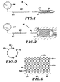
- Figure 1 is a schematic view of a stent deployment device carrying a stent constructed in accordance with the present invention;
- Figure 2 is a schematic view similar to that of Figure 1, showing the stent expanded to an enlarged-radius state;
- Figure 3 is an enlarged end view of the stent;
- Figure 4 is a side elevation of the stent, opened and lying flat, to more clearly show the strand arrangement and weld pattern;
- Figure 5 is a further enlarged view of several strands of the stent;
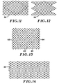
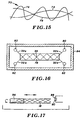
- Figures 6-15 illustrate alternative embodiment stents, in each case with the stent opened and lying flat;
- Figures 16 and 17 schematically illustrate a process for manufacturing the prosthesis of Figures 3 and 4;
- Figures 18 and 19 schematically illustrate alternative approaches to the radial compression of the stent around the balloon and catheter of Figures 1 and 2; and
- Figure 20 illustrates a stent graft constructed in accordance with the present invention.
- Turning now to the drawings, there is shown in Figures 1 and 2 a
deployment device 16 for delivering a prosthesis, in particular astent 18, to an intended fixation location or treatment site within a body lumen, and then radially enlarging the stent to fix the stent within the lumen. - The device includes an elongate and
flexible catheter 20 constructed of a biocompatible polymer, e.g. polyurethane. A balloon inflation lumen (not shown) runs from aproximal end 22 of the catheter to adistal end 24 of the catheter, where the lumen is open to the interior of anelongate balloon 26 supported at the catheter distal end. Atproximal end 22, the lumen is open to asource 28 of a balloon inflation fluid, e.g. a saline solution.Stent 18, radially compressed into a reduced-radius delivery state, surroundsballoon 26.Catheter 20 also incorporates a guidewire lumen, to facilitate advancing the balloon and catheter distally over a guidewire toward the intended treatment site. In the delivery state,stent 18 typically has a length in the range of 15-30 mm and a diameter of about 1.3 mm. The stent length and diameter can vary, depending on the nature of the procedure and the size of the lumen. - After the catheter has been advanced sufficiently to place the balloon and stent at the treatment site, the balloon inflation fluid is supplied to the balloon under pressure, typically about three atmospheres to inflate
balloon 26 and radially enlargestent 18, thus expanding the stent into an intimate contact with surroundingtissue 30 as shown in Figure 2. The enlarged stent can have a diameter of about 3 mm, or another suitable value within a range of about 2-6 mm. As it is radially enlarged,stent 18 undergoes an axial shortening by an amount that depends on the orientation of the strands or filaments of the stent as well as the amount of radial enlargement. - When the stent has been sufficiently enlarged,
balloon 26 is aspirated by withdrawing the inflation fluid. Then, the balloon andcatheter 20 are proximally withdrawn, leavingstent 18 at the treatment site. -
Stent 18, shown in more detail in Figures 3 and 4, is of open-mesh or open-frame construction. More particularly, the stent is a latticework ofhelically wound strands 32 arranged in two oppositely directed and concentric sets ofhelices Stent 18 is composed of eighteen strands, nine wound in each direction. Each strand runs the length ofstent 18, and has a diameter of about 0.004 inches (0.1 mm). The strands are ductile, each being capable of elongation in the range of about 20-40 percent, more preferably about 30 percent. The stent is plastically deformable, due to the strand ductility. The strands preferably are formed of metal, with tantalum being the most preferred material for its body compatibility as well as ductility. Other, less preferred choices include gold, silver, titanium and 316 steel. - As seen in Figure 3, the eighteen
strands 32 come together in nine pairs of strands, secured to one another by welds 34. The same is true for the opposite end ofstent 18. Between the ends of the stent,strands 32 form multiple crossings or intersections. At some of the crossings, theadjacent strands weld 34. The dots in Figure 4 indicate welds 34.Other crossings 35 are unsecured, and the strands are free for limited movement relative to one another. - The contrast between secured and unsecured strand crossings is seen from Figure 5, where two of
strands 32a and two ofstrands 32b are joined by twowelds 34 and have two unsecured crossings. Broken lines, in greatly exaggerated fashion, illustrate the limited freedom of movement instrands -
Welds 34 are arranged in a selected pattern, to selectively influence the radial stiffness and the axial stiffness ofstent 18. With reference to Figure 4 once again, welds 34 conveniently are considered to be arranged in circumferential rows or rings, which appear as vertical rows in the flattened stent in the figure. The stent includesopposite end regions medial region 40, where the crossings are provided in alternating rings or circumferential rows of secured and unsecured crossings. This welding pattern has been found highly favorable because it provides substantial radial rigidity and strength, while also providing adequate axial flexibility (i.e. bending flexibility about transverse or radial axes) to facilitate distal advancement of the radially compressed stent andballoon 26 through serpentine or curved body passages on their way to the treatment site. The bending flexibility is provided by the alternating rows (rings) of unsecured crossings throughoutmedial region 40. Alongend regions welds 34, to further enhance radial strength and rigidity, thus to provide a more secure fixation ofstent 18 at the treatment site. - A salient advantage of the invention resides in the radial stiffness provided by the welds, which enables a winding of
helical strands 32 at substantially reduced braid angles. Figure 4 illustrates a longitudinal axis 42 ofstent 18. Each strand is wound at a pitch or angle α/2 with respect to the longitudinal axis. In each case, the pitch is approximately 30 degrees. Instent 18 the helices are symmetrical. Consequently the braid angle α is twice the pitch, i.e. 60 degrees. - In stent designs in which the strands are joined, if at all, only at the ends of the stent, the strands themselves provide the radial strength and rigidity. Accordingly, achieving satisfactory radial strength requires large braid angles, preferably at least about 110 degrees (equivalent to pitches of 55 degrees). The greater the braid angle, the greater the radial strength for a given diameter stent construction and strand size. A disadvantage on the larger braid angles is that for a given radial expansion, the stent undergoes substantial axial shortening. Conversely, when the strands form smaller braid angles, a given radial enlargement of the stent results in substantially less axial shortening. More particularly, using welds to impart radial strength enables braid angles in the range of 30 degrees to 75 degrees (equivalent to a pitch in the range of 15-37.5 degrees), rather than braid angles of, for example, 110-140 degrees.
- The above advantages are obtainable through a variety of weld patterns, as indicated by the following examples, all of which involve stents shown in an opened, flat condition to more clearly illustrate the strand arrangements and weld patterns:
- Figure 6 illustrates a
stent 44 formed of 18 strands, 9 helically wound in each of two opposite directions.Welds 34 are formed at selected strand crossings, at a density of about 1/3, in terms of the ratio of welds to total crossings. As indicated by aline 46, welds 34 are arranged in a helical pattern with an effective pitch θ substantially greater (steeper) than the pitch α/2 of the strands. The higher effective pitch increases radial rigidity, as compared to a pattern of welds that matches the pitch of the strands. - Figure 7 illustrates a
stent 48 formed of opposed sets ofhelical strands stent 44 in Figure 6, adjacent turns of the helix formed by the welds are spaced apart from one another by a greater axial distance. This arrangement enhances axial bending flexibility, and like the arrangement in Figure 6 extends for the entire axial length of the stent. The weld density is about 1/9. - Figure 8 shows a
stent 50 formed of two sets of oppositely directedhelical strands Welds 34 are arranged in a helical pattern. Once again, the weld density is about 1/9. However, in contrast tostent 48 in Figure 7, the effective pitch of the pattern is steeper, and the axial spacing between adjacent turns of the helical pattern is reduced. The result, assuming other factors are equal, is greater radial rigidity and reduced axial bending flexibility. - Figure 9 illustrates a
stent 52 formed of oppositely wound sets ofhelical strands - Figure 10 illustrates another
stent 54 having a helical pattern in which each turn of the pattern includes four parallel rows ofwelds 34. The effective pitch of θ the pattern is about 60 degrees, and is in the opposite direction from the pitch shown in Figure 9. - Figure 11 illustrates a
stent 56 composed of oppositely directed sets ofhelical strands - Figure 12 illustrates a
stent 58 formed of sets of oppositely directedhelical strands stent 58 are trimmed to correspond to the weld pattern, which reduces the number of welds required. - Figure 13 illustrates a
stent 60 includingopposite end regions medial region 66 along which the welds form a helical pattern. - Figure 14 illustrates an
alternative embodiment stent 62 formed of oppositely directed sets ofhelically wound strands Welds 34 form a series of adjacent pairs of rings or circumferential rows, alternating with pairs of rings or rows of unsecured crossings. This arrangement provides a combination of radial rigidity and axial bending flexibility similar tostent 18 in Figure 4, althoughstent 18 is more preferred. - Figure 15 illustrates a
stent 70 formed of helically woundstrands strand 76 wound at a steeper pitch. - While the present invention has been discussed primarily in connection with plastically deformable stents, weld patterns likewise can be used to enhance the radial strength of radially self-expanding stents. In such stents the strands tend to be resilient rather than ductile, formed of materials such as cobalt-based alloys sold under the brand names "Elgioly" "Phynox" and "MP35N", as well as certain stainless spring steels. The resulting stents exhibit reduced axial shortening for a given degree of radial expansion, and have enhanced resistance to radial compression without sacrificing axial bending flexibility.
- Further, stents according to the present invention can be formed of composite strands formed using DFT (drawn filled tubing) processes or the like, for example with a core of tantalum or of a titanium nickel alloy, surrounded by an Elgioly casing. The core preferably constitutes from about 25 percent to about 33 percent of the cross sectional area of the composite strand. The percentage is variable, based on the materials involved, to achieve a desired resiliency or ductility of the composite strand.
- Stents constructed according to the present invention exhibit several advantages, regardless of whether they are of the plastically deformable or self-expanding type. These include greater visibility, because the helical winding construction results in a higher metal surface area as a percentage of the entire surface area of the stent. Compared with certain known configurations, e.g. the undulating configurations of the aforementioned '396 patent, stent fabrication is less complex. Further, the helical arrangement, in which the individual strands extend for the entire length of the stent, affords greater structural integrity, particularly when the stent is subjected to tensile stress.
-
Stent 18 exhibits an excellent resistance to recoil after radial expansion. More particularly, the external diameter of the stent, measured whileballoon 26 was inflated, was 4.03 millimeters. After balloon deflation, the external diameter was measured at 3.98 millimeters, for a reduction in diameter of just 0.05 millimeters, the least among several stents tested.Stent 18 also exhibited superior radial rigidity. When tested for the hoop force in the collar sufficient to cause a 25% reduction in diameter from the original expanded diameter,stent 18 required the highest force, 0.18 lb. The highest value from among the other stents tested was 0.10 lb. -
Stent 18 and the other stent embodiments shown in Figures 5-15, are fabricated first by interbraiding the sets of strands. Figure 16 shows two structural strands (tantalum filaments) 32a and 32b, one from each set of oppositely directed structural strands, wound about amandrel 78 and supported byrespective bobbins - While wound about the mandrel, the tantalum strands are annealed within a
furnace 84, preferably for about 30 minutes at a temperature of about 1100°C. - After annealing, the tubular structure composed of the strands is cleaned by washing or passivation, then mounted on another
mandrel 86 for welding. As seen in Figure 17, a resistance welding process is employed usingelectrodes - The preferred manner of welding is resistance welding, which uses pressure and heat generated due to the electrical resistance of the strands being joined. Preferably, the strands are joined using current and pressure settings appropriate for spot welding, without excessive formation of flash, while still forming a durable weld. Certain situations may call for weld penetration in excess of 20 percent, i.e. beyond the traditional definition of a spot weld. Variables such as weld current, hold time, hold cycles, the number of weld cycles, the electrode diameter and the electrode pressure or clamping force may require adjustment for best results. A consistent current path must be maintained, and a constant current mode is preferred. Also, heat treatment may be required after welding, to obtain optimum mechanical properties.
- In preparing
stent 18, welds were formed using a Unitek Miyachi Series 300 Weld Head System Model 350, and a Model HF2 two kilohertz high frequency resistance welding power supply. The electrodes are copper, and the mandrel is beryllium copper. Suitable currents are in the range of about 300-600 amperes, and clamping force is preferably within the range of 2-15 lb. - Laser welding is an alternative, e.g. using a Unitek/Benchmark Industries DE9000 50 W Nd: YAG laser. A single pulse mode is preferred, and a flow of argon gas preferably is maintained over the weld area. Welding pulse times can be 1.2-1.5 ms, more preferably 1.3 ms. Laser energy can ranged from about 0.6-1.5 J, preferably about 0.5 J; and power is in the range of 0.81-1.72 kW, preferably about 0.90 kW.
- Another laser welding alternative is to use a CO2 laser.
-
Strands 32 also may be joined by use of ultrasonic energy. The ultrasonic energy is used to cause mechanical vibrations at the interface of the strands, providing a friction weld. - Induction welding generates thermal energy within the strands by magnetic inductive heating, and may be the closest alternative to resistance welding.
- Stent strands may be joined by braising or soldering, involving the use of a metal having a lower melting point to create the bond. A flux may be required.
- Other possible alternatives include electron beam welding, which involves heating the strands with the kinetic energy of accelerated electrons, and affords the possibility of superior control over weld area and penetration; arc welding, with or without filler material; sinter bonding or solid state diffusion bonding, which may involve use of an interlayer; friction welding, involving galling of the interface between strands, due to their relative movement; and explosive bonding based on pressure shock waves.
- In preparation for its eventual deployment,
stent 18 must be reduced radially to the delivery state while positioned in surrounding relation tocatheter 20 andballoon 26. The radial compression ofstent 18 must be done with care, to avoid producing distortions or irregularities during radial contraction. To this end, avacuum crimping tool 92, shown in Figure 18, can be used to crimp the stent.Tool 92 includes arigid cylinder 94 providing a vacuum chamber, and a length ofelastomeric tubing 96 extending from one end of the cylinder to the other.Tubing 96 has an inner diameter approximately equal to that ofballoon catheter 18. Aconnector 98 provides a path from the chamber to asyringe 100 or a vacuum pump capable of generating a vacuum within the cylinder. Drawing a vacuum within the cylinder causes a pressure imbalance, withelastomeric tubing 96 expanding radially in response to the imbalance. - When the vacuum (or partial vacuum) has sufficiently expanded
tubing 96, e.g. to a 6 mm diameter,catheter 20 andballoon 26, along withstent 18 in surrounding relation to the balloon, are inserted intoelastomeric tubing 96. Then, the vacuum is released, causingtubing 96 to contract under its residual elastic force, to compressstent 18 firmly onto the balloon. After stent compression, the vacuum is reapplied and the stent, catheter and balloon are withdrawn from the elastomeric tubing. - Figure 19 illustrates an
alternative tool 102 for using pressure in lieu of a vacuum to radially compress the stent. More particularly, the tool is an inflatable balloon-like member having aninternal sleeve 104 for receiving the catheter, balloon and surrounding stent, and anannular chamber 106 surrounding the sleeve. Abulb 108 is operable to inflatemember 102 after the catheter, balloon and stent have been inserted intosleeve 104. Inflation radially compresses the sleeve, thus to compress the stent. Following compression, the inflatable member is aspirated to release the catheter, balloon and stent. - Figure 20 illustrates a
stent graft 110 including astructural layer 112 formed ofinterbraided strands 32 selectively welded according to the present invention.Layer 112 supports agraft layer 114 that is substantially impervious to blood and other body fluids.Graft layer 114, for example, can be formed of interwoven multifilament yarns. Suitable materials include PET, polypropylene, polyurethane, polycarbonateurethane, HDPE, polyethylene, silicone, PTFE, ePTFU, and polyolefin.Stent graft 110 is particularly well suited for fixation within a blood vessel to shunt blood past an aneurysm, and alternatively can be used to structurally support weakened portions of other body lumens. - Thus in accordance with the present invention, stents and stent grafts are formed of helical strands welded at selected crossings or intersections, to provide weld patterns that enhance radial rigidity without significantly reducing axial bending flexibility, or otherwise favorably influence said characteristics. The use of welds to increase radial strength enables the winding of opposed helical strands at substantially reduced braid angles, reducing the degree of axial shortening for a given amount of radial enlargement of the stent. The stent exhibits virtually no recoil after its fixation, and also exhibits a high radial resistance to compression, and good visibility when fluoroscopic techniques are employed.
Claims (33)
- A body insertable prosthesis, including:a radially enlargeable stent (18) including a plurality of strands (32) helically wound in different directions to form multiple crossings including a plurality of secured crossings (34) at which the adjacent strands (32a, 32b) are integrally secured to one another, characterized in that said multiple crossings include a plurality of unsecured crossings (35) at which the adjacent strands (32a, 32b) are free for limited movement relative to one another,wherein the secured crossings (34) are arranged in a selected pattern throughout a selected axial region of the stent (18) to selectively influence a radial stiffness of the stent, the selected pattern being helical or comprising of a plurality of circumferential rows of the secured crossings.
- The prosthesis of claim 1, wherein the secured crossings (34) have a density , in terms of a ratio of secured crossings to all crossings, in the range of about 10-90 percent.
- The prosthesis of claim 2, wherein said density is about 40-80 percent.
- The prosthesis of claim 1, wherein the secured crossings (34) are characterized by welds of the adjacent strands (32a, 32b).
- The prosthesis of claim 1, wherein the strands (32) form a latticework of first and second sets of the helical strands running in opposite directions.
- The prosthesis of claim 5, wherein the helical strands (32) are interbraided.
- The prosthesis of claim 5, wherein the helices have substantially the same strand pitch relative to a longitudinal axis of the latticework.
- The prosthesis of claim 7, wherein the selected pattern is helical.
- The prosthesis of claim 8, wherein the helical pattern has an effective pitch, relative to the longitudinal axis, greater than the strand pitch.
- The prosthesis of claim 8, wherein the effective pitch is at least about 45 degrees, and the strand pitch is in the range of about 15 - 37.5 degrees.
- The prosthesis of claim 1, wherein said selected pattern is selected to controllably determine the radial stiffness and influence an axial stiffness of the stent.
- The prosthesis of claim 1, wherein the selected axial region encompasses substantially the entire stent (18).
- The prosthesis of claim 1, wherein the selected axial region comprises a medial region (40) of the stent (18).
- The prosthesis of claim 13, wherein the stent (18) consists substantially of the medial region (40) and first and second end regions (36, 38) on opposite sides of the medial region, said secured crossings (34) are formed at a first density in the medial region and at a second density in the end regions, and wherein the first density is less than the second density.
- The prosthesis of claim 14, wherein said second density is approximately one hundred percent.
- The prosthesis of claim 1, wherein the strands (32) are formed of a flexible material.
- The prosthesis of claim 1, wherein said strands (32) are formed of a plastically deformable material.
- The prosthesis of claim 1, wherein said strands (32) are formed of at least one of the materials from a group comprising: Tantalum, gold, silver, titanium, steel, a cobalt-based alloy, and a titanium nickel alloy.
- A medical device including the prosthesis of claim 1, and further including:• an elongate inflatable balloon (26), in a substantially aspirated condition, surrounded by the stent in a reduced-radius delivery state; and• a means for providing an inflation fluid to the balloon (26) under pressure, to expand the balloon and thereby expand the stent (18) to a radially-enlarged state.
- The device of claim 19 further including an elongate and flexible catheter (20) supporting the elongate balloon (26) along a distal end region of the catheter; wherein the means for providing fluid includes a fluid source (28) near a proximal end of the catheter, and a balloon inflation lumen fluid coupled to the fluid source and to the balloon.
- A process for fabricating a prosthesis, including:• winding a plurality of structural strands (32) helically in different directions to provide a generally tubular stent (18) in which the strands cooperate to form multiple crossings of adjacent strands (32a, 32b);• throughout a selected axial region of the stent, bonding the adjacent strands at selected ones of the crossings to form a pattern of bonded crossings (34) while leaving the adjacent strands at other crossings (35) free for limited movement relative to one another, to selectively influence a radial stiffness of the stent, the pattern of bonded crossings (35) being helical or comprising of a plurality of circumferential rows of the bonded crossings (35).
- The process of claim 21 further including after said bonding, cutting the stent (18) to a selected length.
- The process of claim 21, wherein said winding of the strands (32) includes interbraiding the strands on a substantially cylindrical mandrel (78).
- The process of claim 23, further including after said interbraiding, heat treating the braided strands (32) to anneal the strands.
- The process of claim 24, wherein the heat treating comprises maintaining the strands (32) at a temperature of about 1100°C for approximately 30 minutes.
- The process of claim 21, wherein the bonding step includes supporting the stent (18) on a mandrel (86).
- The process of claim 21 further including:• inserting an elongate inflatable balloon (26) axially into the stent (18), so that the stent over substantially its entire length surrounds the balloon; and• with the stent surrounding the balloon, plastically deforming the strands (32) to radially contract the stent about the balloon, while maintaining the balloon in a substantially aspirated condition.
- The process of claim 27, wherein the contraction of the stent (18) comprises providing an elastic tubing member (96, 104) forming an opening sufficiently large to receive the stent and balloon (26) prior to said radial contraction; inserting the balloon and stent into the opening; and contracting the elastic tubing member radially inwardly about the stent and substantially uniformly along the length of the stent.
- The process of claim 28, wherein• the tubing member (96, 104) is disposed within the a vacuum chamber and radially enlargeable responsive to at least a partial evacuation of the chamber; and• wherein the contraction of the stent comprises generating at least a partial vacuum, inserting the stent and balloon into the opening during vacuum generation, and releasing the vacuum to allow the tubing member to radially compress the stent.
- The process of claim 28, wherein the tubing member (104) is formed as an interior sleeve portion of an annular inflatable shaping member (102); and said contraction comprises inserting the stent (18) and balloon (26) into the opening while the inflatable member is substantially aspirated, then inflating the inflatable member to radially compress the stent.
- The process of claim 21, wherein said bonding of the adjacent strands (32a, 32b) comprises one of the following: Resistance welding, induction welding, laser welding, ultrasonic welding, braising and soldering.
- The process of claim 21, wherein said selected axial region comprises a medial region (40) of the stent (18), and said bonding further includes bonding the adjacent strands at all crossings throughout end regions (36, 38) of the stent on opposite sides of the medial region.
- The process of claim 21, wherein• said winding includes winding the structural strands (32) at a first pitch; and• said bonding includes forming the pattern of bonded crossings (34) with an effective second pitch greater than the first pitch.
Applications Claiming Priority (3)
| Application Number | Priority Date | Filing Date | Title |
|---|---|---|---|
| US4222697P | 1997-04-15 | 1997-04-15 | |
| US42226P | 1997-04-15 | ||
| PCT/US1998/007821 WO1998046168A1 (en) | 1997-04-15 | 1998-04-15 | Prostheses with selectively welded crossing strands |
Publications (3)
| Publication Number | Publication Date |
|---|---|
| EP0975279A1 EP0975279A1 (en) | 2000-02-02 |
| EP0975279A4 EP0975279A4 (en) | 2003-05-07 |
| EP0975279B1 true EP0975279B1 (en) | 2007-05-02 |
Family
ID=21920750
Family Applications (1)
| Application Number | Title | Priority Date | Filing Date |
|---|---|---|---|
| EP98915625A Expired - Lifetime EP0975279B1 (en) | 1997-04-15 | 1998-04-15 | Prostheses with selectively welded crossing strands |
Country Status (5)
| Country | Link |
|---|---|
| US (2) | US6027529A (en) |
| EP (1) | EP0975279B1 (en) |
| AT (1) | ATE361040T1 (en) |
| DE (1) | DE69837704T2 (en) |
| WO (1) | WO1998046168A1 (en) |
Cited By (4)
| Publication number | Priority date | Publication date | Assignee | Title |
|---|---|---|---|---|
| DE102016102503A1 (en) | 2016-02-12 | 2017-08-17 | Rheinisch-Westfälische Technische Hochschule Aachen (RWTH) | Method of making a stent and stent |
| US10888444B2 (en) | 2017-11-01 | 2021-01-12 | Boston Scientific Scimed, Inc. | Esophageal stent including a valve member |
| US11304795B2 (en) | 2017-10-25 | 2022-04-19 | Boston Scientific Scimed, Inc. | Stent with atraumatic spacer |
| US12508012B2 (en) | 2017-03-22 | 2025-12-30 | Boston Scientific Medical Device Limited | Retrievable access valve |
Families Citing this family (89)
| Publication number | Priority date | Publication date | Assignee | Title |
|---|---|---|---|---|
| US6039749A (en) | 1994-02-10 | 2000-03-21 | Endovascular Systems, Inc. | Method and apparatus for deploying non-circular stents and graftstent complexes |
| DE4424242A1 (en) * | 1994-07-09 | 1996-01-11 | Ernst Peter Prof Dr M Strecker | Endoprosthesis implantable percutaneously in a patient's body |
| EP0891752B1 (en) * | 1997-07-17 | 2005-01-12 | Schneider (Europe) GmbH | Stent and method for manufacturing such a stent |
| US6070589A (en) | 1997-08-01 | 2000-06-06 | Teramed, Inc. | Methods for deploying bypass graft stents |
| US6290731B1 (en) | 1998-03-30 | 2001-09-18 | Cordis Corporation | Aortic graft having a precursor gasket for repairing an abdominal aortic aneurysm |
| US6887268B2 (en) | 1998-03-30 | 2005-05-03 | Cordis Corporation | Extension prosthesis for an arterial repair |
| US7500988B1 (en) * | 2000-11-16 | 2009-03-10 | Cordis Corporation | Stent for use in a stent graft |
| ES2313882T3 (en) * | 1999-02-01 | 2009-03-16 | Board Of Regents, The University Of Texas System | ENDOVASCULAR PROTESTS FORKED AND FORKED FABRICS AND PROCEDURE FOR MANUFACTURING THE SAME. |
| US7018401B1 (en) | 1999-02-01 | 2006-03-28 | Board Of Regents, The University Of Texas System | Woven intravascular devices and methods for making the same and apparatus for delivery of the same |
| FR2791550A1 (en) * | 1999-03-29 | 2000-10-06 | Jean Francois Delforge | Setter for intraluminal endoprosthesis in cardiology uses pressurized inner chamber, and axial cells along axial channel to avoid channel to be crushed under pressure |
| US6334571B1 (en) | 1999-11-19 | 2002-01-01 | A.R.D. Industries Ltd. | Thin interlayer friction welding |
| US6554854B1 (en) * | 1999-12-10 | 2003-04-29 | Scimed Life Systems, Inc. | Process for laser joining dissimilar metals and endoluminal stent with radiopaque marker produced thereby |
| GB0003387D0 (en) | 2000-02-14 | 2000-04-05 | Angiomed Ag | Stent matrix |
| US6520984B1 (en) | 2000-04-28 | 2003-02-18 | Cardiovasc, Inc. | Stent graft assembly and method |
| US20030114918A1 (en) | 2000-04-28 | 2003-06-19 | Garrison Michi E. | Stent graft assembly and method |
| WO2001082833A2 (en) * | 2000-04-28 | 2001-11-08 | Cardiovasc, Inc. | Stent graft assembly and method |
| IL137326A0 (en) * | 2000-07-17 | 2001-07-24 | Mind Guard Ltd | Implantable braided stroke preventing device and method of manufacturing |
| US7267685B2 (en) | 2000-11-16 | 2007-09-11 | Cordis Corporation | Bilateral extension prosthesis and method of delivery |
| US6843802B1 (en) | 2000-11-16 | 2005-01-18 | Cordis Corporation | Delivery apparatus for a self expanding retractable stent |
| US7314483B2 (en) * | 2000-11-16 | 2008-01-01 | Cordis Corp. | Stent graft with branch leg |
| US6942692B2 (en) | 2000-11-16 | 2005-09-13 | Cordis Corporation | Supra-renal prosthesis and renal artery bypass |
| US7229472B2 (en) | 2000-11-16 | 2007-06-12 | Cordis Corporation | Thoracic aneurysm repair prosthesis and system |
| US6562022B2 (en) * | 2000-12-13 | 2003-05-13 | Advanced Cardiovascular Systems, Inc. | Catheter with enhanced reinforcement |
| WO2002070167A1 (en) * | 2001-03-05 | 2002-09-12 | Idev Technologies, Inc. | Methods for securing strands of woven medical devices |
| JP2002315834A (en) * | 2001-04-20 | 2002-10-29 | Asahi Intecc Co Ltd | Catheter tube |
| WO2002087473A1 (en) * | 2001-04-26 | 2002-11-07 | Vascular Innovation, Inc. | Endoluminal device and method for fabricating same |
| US20030100945A1 (en) * | 2001-11-23 | 2003-05-29 | Mindguard Ltd. | Implantable intraluminal device and method of using same in treating aneurysms |
| EP1414612B1 (en) * | 2001-08-07 | 2009-12-23 | Fraunhofer-Gesellschaft zur Förderung der angewandten Forschung e.V. | Laser beam welding method |
| US6712843B2 (en) * | 2001-11-20 | 2004-03-30 | Scimed Life Systems, Inc | Stent with differential lengthening/shortening members |
| US20030135265A1 (en) * | 2002-01-04 | 2003-07-17 | Stinson Jonathan S. | Prostheses implantable in enteral vessels |
| US7326237B2 (en) * | 2002-01-08 | 2008-02-05 | Cordis Corporation | Supra-renal anchoring prosthesis |
| US7255770B2 (en) * | 2002-08-12 | 2007-08-14 | Mentor Corporation | Method for laser welding flexible polymers |
| US7704276B2 (en) * | 2002-11-15 | 2010-04-27 | Synecor, Llc | Endoprostheses and methods of manufacture |
| US6777647B1 (en) | 2003-04-16 | 2004-08-17 | Scimed Life Systems, Inc. | Combination laser cutter and cleaner |
| US7951557B2 (en) * | 2003-04-27 | 2011-05-31 | Protalix Ltd. | Human lysosomal proteins from plant cell culture |
| US20100196345A1 (en) * | 2003-04-27 | 2010-08-05 | Protalix | Production of high mannose proteins in plant culture |
| ATE504272T1 (en) | 2003-05-23 | 2011-04-15 | Boston Scient Ltd | STENTS WITH LOOP ATTACHED |
| JP3709197B2 (en) * | 2003-08-25 | 2005-10-19 | 松下電器産業株式会社 | Cylindrical battery and manufacturing method thereof |
| US20070191929A1 (en) * | 2003-08-27 | 2007-08-16 | Cook Incorporated | Medical devices using magnetic pulse welding |
| US20050182474A1 (en) * | 2004-02-13 | 2005-08-18 | Medtronic Vascular, Inc. | Coated stent having protruding crowns and elongated struts |
| US7309461B2 (en) * | 2004-04-12 | 2007-12-18 | Boston Scientific Scimed, Inc. | Ultrasonic crimping of a varied diameter vascular graft |
| US7389670B1 (en) | 2004-07-26 | 2008-06-24 | Abbott Laboratories | Stent crimping system |
| ATE477768T1 (en) * | 2004-09-21 | 2010-09-15 | Cook William A Australia | STENT PROSTHESIS CONNECTION ARRANGEMENT |
| US20060085065A1 (en) * | 2004-10-15 | 2006-04-20 | Krause Arthur A | Stent with auxiliary treatment structure |
| US8337543B2 (en) * | 2004-11-05 | 2012-12-25 | Boston Scientific Scimed, Inc. | Prosthesis anchoring and deploying device |
| US9545300B2 (en) * | 2004-12-22 | 2017-01-17 | W. L. Gore & Associates, Inc. | Filament-wound implantable devices |
| US8109941B2 (en) | 2005-02-28 | 2012-02-07 | Boston Scientific Scimed, Inc. | Distal release retrieval assembly and related methods of use |
| US8187318B2 (en) * | 2005-08-31 | 2012-05-29 | Advanced Bio Prosthetic Surfaces, Ltd. | Covered stent with proximal and distal attachment, delivery catheter, and method of making same |
| US8182522B2 (en) * | 2005-11-17 | 2012-05-22 | The Cleveland Clinic Foundation | Apparatus and method for delivering lined intraluminal prostheses |
| WO2007061801A2 (en) * | 2005-11-17 | 2007-05-31 | The Cleveland Clinic Foundation | Method and apparatus for compressing intraluminal prostheses |
| US8066760B2 (en) * | 2006-04-18 | 2011-11-29 | Medtronic Vascular, Inc. | Stent with movable crown |
| DE102006019856A1 (en) * | 2006-04-28 | 2007-11-08 | Admedes Schuessler Gmbh | Process for working materials using porous silicon as explosive |
| US8252036B2 (en) | 2006-07-31 | 2012-08-28 | Syntheon Cardiology, Llc | Sealable endovascular implants and methods for their use |
| US9585743B2 (en) | 2006-07-31 | 2017-03-07 | Edwards Lifesciences Cardiaq Llc | Surgical implant devices and methods for their manufacture and use |
| US9408607B2 (en) | 2009-07-02 | 2016-08-09 | Edwards Lifesciences Cardiaq Llc | Surgical implant devices and methods for their manufacture and use |
| JP5455633B2 (en) | 2006-10-22 | 2014-03-26 | アイデブ テクノロジーズ インコーポレイテッド | Devices and methods for stent advancement |
| WO2008051935A1 (en) | 2006-10-22 | 2008-05-02 | Idev Technologies, Inc. | Methods for securing strand ends and the resulting devices |
| US20080127707A1 (en) * | 2006-11-30 | 2008-06-05 | Abbott Laboratories | Stent crimping assembly and method |
| EP2150608B1 (en) * | 2007-05-07 | 2017-11-29 | Protalix Ltd. | Large scale disposable bioreactor |
| US20080319534A1 (en) * | 2007-06-22 | 2008-12-25 | Medtronic Vascular, Inc. | Stent With Improved Mechanical Properties |
| US9814611B2 (en) | 2007-07-31 | 2017-11-14 | Edwards Lifesciences Cardiaq Llc | Actively controllable stent, stent graft, heart valve and method of controlling same |
| US9566178B2 (en) | 2010-06-24 | 2017-02-14 | Edwards Lifesciences Cardiaq Llc | Actively controllable stent, stent graft, heart valve and method of controlling same |
| US8303650B2 (en) | 2008-01-10 | 2012-11-06 | Telesis Research, Llc | Biodegradable self-expanding drug-eluting prosthesis |
| US8317857B2 (en) * | 2008-01-10 | 2012-11-27 | Telesis Research, Llc | Biodegradable self-expanding prosthesis |
| JP5243080B2 (en) * | 2008-03-31 | 2013-07-24 | テルモ株式会社 | In vivo indwelling stent and biological organ dilator |
| DE102008033170A1 (en) * | 2008-07-15 | 2010-01-21 | Acandis Gmbh & Co. Kg | A braided mesh implant and method of making such an implant |
| US20110319987A1 (en) | 2009-05-20 | 2011-12-29 | Arsenal Medical | Medical implant |
| US9265633B2 (en) | 2009-05-20 | 2016-02-23 | 480 Biomedical, Inc. | Drug-eluting medical implants |
| US9309347B2 (en) | 2009-05-20 | 2016-04-12 | Biomedical, Inc. | Bioresorbable thermoset polyester/urethane elastomers |
| WO2010135433A1 (en) * | 2009-05-20 | 2010-11-25 | Arsenal Medical, Inc. | Medical implant |
| US8992601B2 (en) | 2009-05-20 | 2015-03-31 | 480 Biomedical, Inc. | Medical implants |
| US8888840B2 (en) * | 2009-05-20 | 2014-11-18 | Boston Scientific Scimed, Inc. | Drug eluting medical implant |
| US8372133B2 (en) | 2009-10-05 | 2013-02-12 | 480 Biomedical, Inc. | Polymeric implant delivery system |
| US9023095B2 (en) | 2010-05-27 | 2015-05-05 | Idev Technologies, Inc. | Stent delivery system with pusher assembly |
| US9827093B2 (en) | 2011-10-21 | 2017-11-28 | Edwards Lifesciences Cardiaq Llc | Actively controllable stent, stent graft, heart valve and method of controlling same |
| CN106659516A (en) * | 2014-07-01 | 2017-05-10 | 波士顿科学国际有限公司 | overlapping braid ends |
| US10792194B2 (en) | 2014-08-26 | 2020-10-06 | Curt G. Joa, Inc. | Apparatus and methods for securing elastic to a carrier web |
| US10213290B2 (en) | 2016-02-17 | 2019-02-26 | Boston Scientific Scimed, Inc. | Braided stent and method of manufacturing a braided stent |
| EP3746021B1 (en) | 2018-01-29 | 2024-01-31 | Curt G. Joa, Inc. | Apparatus and method of manufacturing an elastic composite structure for an absorbent sanitary product |
| US11065136B2 (en) * | 2018-02-08 | 2021-07-20 | Covidien Lp | Vascular expandable devices |
| US11065009B2 (en) | 2018-02-08 | 2021-07-20 | Covidien Lp | Vascular expandable devices |
| DE102018120939A1 (en) | 2018-08-28 | 2020-03-05 | Biotronik Ag | Method and device for fixing a stent to a balloon of a balloon catheter |
| CN113329716A (en) * | 2018-11-16 | 2021-08-31 | 微仙美国有限公司 | Radiopaque vascular prosthesis |
| US12616617B2 (en) | 2018-12-31 | 2026-05-05 | Curt G. Joa, Inc. | Apparatus and method of manufacturing an elastic composite structure for an absorbent sanitary product |
| US11925538B2 (en) | 2019-01-07 | 2024-03-12 | Curt G. Joa, Inc. | Apparatus and method of manufacturing an elastic composite structure for an absorbent sanitary product |
| WO2020257155A1 (en) * | 2019-06-17 | 2020-12-24 | Boston Scientific Scimed, Inc. | Covered endoprosthesis with improved branch access |
| US12433797B2 (en) | 2019-09-04 | 2025-10-07 | Curt G. Joa, Inc. | Elastic entrapment with waist cap bonding |
| US11173072B2 (en) | 2019-09-05 | 2021-11-16 | Curt G. Joa, Inc. | Curved elastic with entrapment |
| MX2022010076A (en) | 2020-02-17 | 2022-09-02 | Joa Curt G Inc | An elastic composite structure for an absorbent sanitary product and an apparatus and method for making said elastic composite structure. |
Family Cites Families (21)
| Publication number | Priority date | Publication date | Assignee | Title |
|---|---|---|---|---|
| SE445884B (en) * | 1982-04-30 | 1986-07-28 | Medinvent Sa | DEVICE FOR IMPLANTATION OF A RODFORM PROTECTION |
| US4733665C2 (en) * | 1985-11-07 | 2002-01-29 | Expandable Grafts Partnership | Expandable intraluminal graft and method and apparatus for implanting an expandable intraluminal graft |
| US5226913A (en) * | 1988-09-01 | 1993-07-13 | Corvita Corporation | Method of making a radially expandable prosthesis |
| US5171262A (en) * | 1989-06-15 | 1992-12-15 | Cordis Corporation | Non-woven endoprosthesis |
| US5015253A (en) * | 1989-06-15 | 1991-05-14 | Cordis Corporation | Non-woven endoprosthesis |
| DE9010130U1 (en) | 1989-07-13 | 1990-09-13 | American Medical Systems, Inc., Minnetonka, Minn. | Instrument for attaching an expansion implant |
| US5304200A (en) * | 1991-05-29 | 1994-04-19 | Cordis Corporation | Welded radially expandable endoprosthesis and the like |
| JP2961287B2 (en) * | 1991-10-18 | 1999-10-12 | グンゼ株式会社 | Biological duct dilator, method for producing the same, and stent |
| BE1006440A3 (en) * | 1992-12-21 | 1994-08-30 | Dereume Jean Pierre Georges Em | Luminal endoprosthesis AND METHOD OF PREPARATION. |
| FI953472A0 (en) * | 1993-01-19 | 1995-07-18 | Schneider Usa Inc | Coated, combined tension frame |
| US5328469A (en) | 1993-03-19 | 1994-07-12 | Roger Coletti | Hybrid balloon angioplasty catheter and methods of use |
| US5437083A (en) * | 1993-05-24 | 1995-08-01 | Advanced Cardiovascular Systems, Inc. | Stent-loading mechanism |
| GB2281865B (en) * | 1993-09-16 | 1997-07-30 | Cordis Corp | Endoprosthesis having multiple laser welded junctions,method and procedure |
| US5549663A (en) | 1994-03-09 | 1996-08-27 | Cordis Corporation | Endoprosthesis having graft member and exposed welded end junctions, method and procedure |
| US5575818A (en) * | 1995-02-14 | 1996-11-19 | Corvita Corporation | Endovascular stent with locking ring |
| WO1996028116A1 (en) * | 1995-03-10 | 1996-09-19 | Cardiovascular Concepts, Inc. | Tubular endoluminar prosthesis having oblique ends |
| US5746764A (en) * | 1995-12-04 | 1998-05-05 | Atrion Medical Products, Inc. | Stent compression instrument |
| EP0801934B1 (en) * | 1996-04-16 | 2000-06-14 | Medtronic, Inc. | Welded sinusoidal wave stent |
| DE19633901A1 (en) * | 1996-08-22 | 1998-02-26 | Thomas Prof Dr Med Ischinger | Vascular support in the form of a tube section-like support structure |
| US5725519A (en) * | 1996-09-30 | 1998-03-10 | Medtronic Instent Israel Ltd. | Stent loading device for a balloon catheter |
| US5893867A (en) * | 1996-11-06 | 1999-04-13 | Percusurge, Inc. | Stent positioning apparatus and method |
-
1998
- 1998-04-15 DE DE69837704T patent/DE69837704T2/en not_active Expired - Fee Related
- 1998-04-15 US US09/060,695 patent/US6027529A/en not_active Expired - Fee Related
- 1998-04-15 EP EP98915625A patent/EP0975279B1/en not_active Expired - Lifetime
- 1998-04-15 WO PCT/US1998/007821 patent/WO1998046168A1/en not_active Ceased
- 1998-04-15 AT AT98915625T patent/ATE361040T1/en not_active IP Right Cessation
-
2000
- 2000-02-22 US US09/510,209 patent/US6295714B1/en not_active Expired - Lifetime
Cited By (7)
| Publication number | Priority date | Publication date | Assignee | Title |
|---|---|---|---|---|
| DE102016102503A1 (en) | 2016-02-12 | 2017-08-17 | Rheinisch-Westfälische Technische Hochschule Aachen (RWTH) | Method of making a stent and stent |
| WO2017137577A1 (en) | 2016-02-12 | 2017-08-17 | Innovations- Und Informationszentrum Scheiden Und Fügen E.V. | Method for manufacturing a stent, and stent |
| US12508012B2 (en) | 2017-03-22 | 2025-12-30 | Boston Scientific Medical Device Limited | Retrievable access valve |
| US11304795B2 (en) | 2017-10-25 | 2022-04-19 | Boston Scientific Scimed, Inc. | Stent with atraumatic spacer |
| US12064333B2 (en) | 2017-10-25 | 2024-08-20 | Boston Scientific Scimed, Inc. | Stent with atraumatic spacer |
| US10888444B2 (en) | 2017-11-01 | 2021-01-12 | Boston Scientific Scimed, Inc. | Esophageal stent including a valve member |
| US11771574B2 (en) | 2017-11-01 | 2023-10-03 | Boston Scientific Scimed, Inc. | Esophageal stent including a valve member |
Also Published As
| Publication number | Publication date |
|---|---|
| EP0975279A4 (en) | 2003-05-07 |
| DE69837704D1 (en) | 2007-06-14 |
| EP0975279A1 (en) | 2000-02-02 |
| US6295714B1 (en) | 2001-10-02 |
| US6027529A (en) | 2000-02-22 |
| ATE361040T1 (en) | 2007-05-15 |
| WO1998046168A1 (en) | 1998-10-22 |
| DE69837704T2 (en) | 2007-09-06 |
Similar Documents
| Publication | Publication Date | Title |
|---|---|---|
| US6027529A (en) | Protheses with selectively welded crossing strands | |
| WO1998046168A9 (en) | Prostheses with selectively welded crossing strands | |
| US20230404782A1 (en) | Integrated stent repositioning and retrieval loop | |
| JP7206363B2 (en) | implant insertion system | |
| US5913896A (en) | Interwoven dual sinusoidal helix stent | |
| US6136023A (en) | Welded sinusoidal wave stent | |
| US5304200A (en) | Welded radially expandable endoprosthesis and the like | |
| US5824043A (en) | Endoprosthesis having graft member and exposed welded end junctions, method and procedure | |
| JP6816127B2 (en) | Vascular prosthesis | |
| US8382816B2 (en) | Single-piece endoprosthesis with high expansion ratios and atraumatic ends | |
| EP2407127B1 (en) | Atraumatic stent with reduced deployment force | |
| US5758562A (en) | Process for manufacturing braided composite prosthesis | |
| US7211109B2 (en) | Braided composite prosthesis | |
| US9469925B2 (en) | Stent designs and methods of manufacture | |
| US20010000797A1 (en) | Method and apparatus for occluding aneurysms | |
| WO1997026939A1 (en) | Method and apparatus for occluding aneurysms | |
| EP2227163A1 (en) | Implantable device with electrolytically detachable junction having multiple fine wires | |
| CN117460480A (en) | Artificial blood vessel with drawn filling tube | |
| US20220257363A1 (en) | Bifurcated stent grafts, stents, and methods |
Legal Events
| Date | Code | Title | Description |
|---|---|---|---|
| PUAI | Public reference made under article 153(3) epc to a published international application that has entered the european phase |
Free format text: ORIGINAL CODE: 0009012 |
|
| 17P | Request for examination filed |
Effective date: 19991109 |
|
| AK | Designated contracting states |
Kind code of ref document: A1 Designated state(s): AT BE CH CY DE DK ES FI FR GB GR IE IT LI LU MC NL PT SE |
|
| RIN1 | Information on inventor provided before grant (corrected) |
Inventor name: KLIMA, DANIEL, J. Inventor name: BADEN, JEANNINE, B. Inventor name: RAEDER-DEVENS, JENNIFER, E. Inventor name: O'CONNOR, MICHAEL, G. Inventor name: HANKH, SUSANNE Inventor name: HOFMANN, EUGEN Inventor name: PINCHUK, LEONARD Inventor name: ROYCHOWDHURY, SURANJAN |
|
| A4 | Supplementary search report drawn up and despatched |
Effective date: 20030326 |
|
| 17Q | First examination report despatched |
Effective date: 20040504 |
|
| RTI1 | Title (correction) |
Free format text: PROSTHESES WITH SELECTIVELY WELDED CROSSING STRANDS |
|
| GRAP | Despatch of communication of intention to grant a patent |
Free format text: ORIGINAL CODE: EPIDOSNIGR1 |
|
| GRAS | Grant fee paid |
Free format text: ORIGINAL CODE: EPIDOSNIGR3 |
|
| GRAA | (expected) grant |
Free format text: ORIGINAL CODE: 0009210 |
|
| AK | Designated contracting states |
Kind code of ref document: B1 Designated state(s): AT BE CH CY DE DK ES FI FR GB GR IE IT LI LU MC NL PT SE |
|
| PG25 | Lapsed in a contracting state [announced via postgrant information from national office to epo] |
Ref country code: LI Free format text: LAPSE BECAUSE OF FAILURE TO SUBMIT A TRANSLATION OF THE DESCRIPTION OR TO PAY THE FEE WITHIN THE PRESCRIBED TIME-LIMIT Effective date: 20070502 Ref country code: FI Free format text: LAPSE BECAUSE OF FAILURE TO SUBMIT A TRANSLATION OF THE DESCRIPTION OR TO PAY THE FEE WITHIN THE PRESCRIBED TIME-LIMIT Effective date: 20070502 Ref country code: CH Free format text: LAPSE BECAUSE OF FAILURE TO SUBMIT A TRANSLATION OF THE DESCRIPTION OR TO PAY THE FEE WITHIN THE PRESCRIBED TIME-LIMIT Effective date: 20070502 |
|
| REG | Reference to a national code |
Ref country code: GB Ref legal event code: FG4D |
|
| REG | Reference to a national code |
Ref country code: CH Ref legal event code: EP |
|
| REG | Reference to a national code |
Ref country code: IE Ref legal event code: FG4D |
|
| REF | Corresponds to: |
Ref document number: 69837704 Country of ref document: DE Date of ref document: 20070614 Kind code of ref document: P |
|
| PG25 | Lapsed in a contracting state [announced via postgrant information from national office to epo] |
Ref country code: SE Free format text: LAPSE BECAUSE OF FAILURE TO SUBMIT A TRANSLATION OF THE DESCRIPTION OR TO PAY THE FEE WITHIN THE PRESCRIBED TIME-LIMIT Effective date: 20070802 |
|
| PG25 | Lapsed in a contracting state [announced via postgrant information from national office to epo] |
Ref country code: ES Free format text: LAPSE BECAUSE OF FAILURE TO SUBMIT A TRANSLATION OF THE DESCRIPTION OR TO PAY THE FEE WITHIN THE PRESCRIBED TIME-LIMIT Effective date: 20070813 |
|
| REG | Reference to a national code |
Ref country code: CH Ref legal event code: PL |
|
| PG25 | Lapsed in a contracting state [announced via postgrant information from national office to epo] |
Ref country code: AT Free format text: LAPSE BECAUSE OF FAILURE TO SUBMIT A TRANSLATION OF THE DESCRIPTION OR TO PAY THE FEE WITHIN THE PRESCRIBED TIME-LIMIT Effective date: 20070502 |
|
| EN | Fr: translation not filed | ||
| PG25 | Lapsed in a contracting state [announced via postgrant information from national office to epo] |
Ref country code: PT Free format text: LAPSE BECAUSE OF FAILURE TO SUBMIT A TRANSLATION OF THE DESCRIPTION OR TO PAY THE FEE WITHIN THE PRESCRIBED TIME-LIMIT Effective date: 20071002 Ref country code: DK Free format text: LAPSE BECAUSE OF FAILURE TO SUBMIT A TRANSLATION OF THE DESCRIPTION OR TO PAY THE FEE WITHIN THE PRESCRIBED TIME-LIMIT Effective date: 20070502 |
|
| PLBE | No opposition filed within time limit |
Free format text: ORIGINAL CODE: 0009261 |
|
| STAA | Information on the status of an ep patent application or granted ep patent |
Free format text: STATUS: NO OPPOSITION FILED WITHIN TIME LIMIT |
|
| 26N | No opposition filed |
Effective date: 20080205 |
|
| PG25 | Lapsed in a contracting state [announced via postgrant information from national office to epo] |
Ref country code: IT Free format text: LAPSE BECAUSE OF FAILURE TO SUBMIT A TRANSLATION OF THE DESCRIPTION OR TO PAY THE FEE WITHIN THE PRESCRIBED TIME-LIMIT Effective date: 20070502 Ref country code: GR Free format text: LAPSE BECAUSE OF FAILURE TO SUBMIT A TRANSLATION OF THE DESCRIPTION OR TO PAY THE FEE WITHIN THE PRESCRIBED TIME-LIMIT Effective date: 20070803 Ref country code: FR Free format text: LAPSE BECAUSE OF FAILURE TO SUBMIT A TRANSLATION OF THE DESCRIPTION OR TO PAY THE FEE WITHIN THE PRESCRIBED TIME-LIMIT Effective date: 20071228 |
|
| BERE | Be: lapsed |
Owner name: SCHNEIDER (USA) INC. Effective date: 20080430 |
|
| PG25 | Lapsed in a contracting state [announced via postgrant information from national office to epo] |
Ref country code: MC Free format text: LAPSE BECAUSE OF NON-PAYMENT OF DUE FEES Effective date: 20080430 Ref country code: FR Free format text: LAPSE BECAUSE OF FAILURE TO SUBMIT A TRANSLATION OF THE DESCRIPTION OR TO PAY THE FEE WITHIN THE PRESCRIBED TIME-LIMIT Effective date: 20070502 |
|
| GBPC | Gb: european patent ceased through non-payment of renewal fee |
Effective date: 20080415 |
|
| NLV4 | Nl: lapsed or anulled due to non-payment of the annual fee |
Effective date: 20081101 |
|
| PG25 | Lapsed in a contracting state [announced via postgrant information from national office to epo] |
Ref country code: NL Free format text: LAPSE BECAUSE OF NON-PAYMENT OF DUE FEES Effective date: 20081101 Ref country code: DE Free format text: LAPSE BECAUSE OF NON-PAYMENT OF DUE FEES Effective date: 20081101 |
|
| PG25 | Lapsed in a contracting state [announced via postgrant information from national office to epo] |
Ref country code: BE Free format text: LAPSE BECAUSE OF NON-PAYMENT OF DUE FEES Effective date: 20080430 |
|
| PG25 | Lapsed in a contracting state [announced via postgrant information from national office to epo] |
Ref country code: IE Free format text: LAPSE BECAUSE OF NON-PAYMENT OF DUE FEES Effective date: 20080415 |
|
| PG25 | Lapsed in a contracting state [announced via postgrant information from national office to epo] |
Ref country code: GB Free format text: LAPSE BECAUSE OF NON-PAYMENT OF DUE FEES Effective date: 20080415 |
|
| PG25 | Lapsed in a contracting state [announced via postgrant information from national office to epo] |
Ref country code: CY Free format text: LAPSE BECAUSE OF FAILURE TO SUBMIT A TRANSLATION OF THE DESCRIPTION OR TO PAY THE FEE WITHIN THE PRESCRIBED TIME-LIMIT Effective date: 20070502 |
|
| PG25 | Lapsed in a contracting state [announced via postgrant information from national office to epo] |
Ref country code: LU Free format text: LAPSE BECAUSE OF NON-PAYMENT OF DUE FEES Effective date: 20080415 |