EP0974390B1 - Method of joining two or more parts - Google Patents
Method of joining two or more parts Download PDFInfo
- Publication number
- EP0974390B1 EP0974390B1 EP19980113376 EP98113376A EP0974390B1 EP 0974390 B1 EP0974390 B1 EP 0974390B1 EP 19980113376 EP19980113376 EP 19980113376 EP 98113376 A EP98113376 A EP 98113376A EP 0974390 B1 EP0974390 B1 EP 0974390B1
- Authority
- EP
- European Patent Office
- Prior art keywords
- membrane
- foil
- parts
- thermode
- joining
- Prior art date
- Legal status (The legal status is an assumption and is not a legal conclusion. Google has not performed a legal analysis and makes no representation as to the accuracy of the status listed.)
- Expired - Lifetime
Links
Images

Classifications
-
- B—PERFORMING OPERATIONS; TRANSPORTING
- B01—PHYSICAL OR CHEMICAL PROCESSES OR APPARATUS IN GENERAL
- B01D—SEPARATION
- B01D19/00—Degasification of liquids
- B01D19/0031—Degasification of liquids by filtration
-
- B—PERFORMING OPERATIONS; TRANSPORTING
- B01—PHYSICAL OR CHEMICAL PROCESSES OR APPARATUS IN GENERAL
- B01D—SEPARATION
- B01D63/00—Apparatus in general for separation processes using semi-permeable membranes
- B01D63/08—Flat membrane modules
- B01D63/081—Manufacturing thereof
-
- B—PERFORMING OPERATIONS; TRANSPORTING
- B29—WORKING OF PLASTICS; WORKING OF SUBSTANCES IN A PLASTIC STATE IN GENERAL
- B29C—SHAPING OR JOINING OF PLASTICS; SHAPING OF MATERIAL IN A PLASTIC STATE, NOT OTHERWISE PROVIDED FOR; AFTER-TREATMENT OF THE SHAPED PRODUCTS, e.g. REPAIRING
- B29C65/00—Joining or sealing of preformed parts, e.g. welding of plastics materials; Apparatus therefor
- B29C65/02—Joining or sealing of preformed parts, e.g. welding of plastics materials; Apparatus therefor by heating, with or without pressure
- B29C65/18—Joining or sealing of preformed parts, e.g. welding of plastics materials; Apparatus therefor by heating, with or without pressure using heated tools
-
- B—PERFORMING OPERATIONS; TRANSPORTING
- B29—WORKING OF PLASTICS; WORKING OF SUBSTANCES IN A PLASTIC STATE IN GENERAL
- B29C—SHAPING OR JOINING OF PLASTICS; SHAPING OF MATERIAL IN A PLASTIC STATE, NOT OTHERWISE PROVIDED FOR; AFTER-TREATMENT OF THE SHAPED PRODUCTS, e.g. REPAIRING
- B29C66/00—General aspects of processes or apparatus for joining preformed parts
- B29C66/01—General aspects dealing with the joint area or with the area to be joined
- B29C66/05—Particular design of joint configurations
- B29C66/10—Particular design of joint configurations particular design of the joint cross-sections
- B29C66/11—Joint cross-sections comprising a single joint-segment, i.e. one of the parts to be joined comprising a single joint-segment in the joint cross-section
- B29C66/112—Single lapped joints
-
- B—PERFORMING OPERATIONS; TRANSPORTING
- B29—WORKING OF PLASTICS; WORKING OF SUBSTANCES IN A PLASTIC STATE IN GENERAL
- B29C—SHAPING OR JOINING OF PLASTICS; SHAPING OF MATERIAL IN A PLASTIC STATE, NOT OTHERWISE PROVIDED FOR; AFTER-TREATMENT OF THE SHAPED PRODUCTS, e.g. REPAIRING
- B29C66/00—General aspects of processes or apparatus for joining preformed parts
- B29C66/01—General aspects dealing with the joint area or with the area to be joined
- B29C66/05—Particular design of joint configurations
- B29C66/10—Particular design of joint configurations particular design of the joint cross-sections
- B29C66/11—Joint cross-sections comprising a single joint-segment, i.e. one of the parts to be joined comprising a single joint-segment in the joint cross-section
- B29C66/112—Single lapped joints
- B29C66/1122—Single lap to lap joints, i.e. overlap joints
-
- B—PERFORMING OPERATIONS; TRANSPORTING
- B29—WORKING OF PLASTICS; WORKING OF SUBSTANCES IN A PLASTIC STATE IN GENERAL
- B29C—SHAPING OR JOINING OF PLASTICS; SHAPING OF MATERIAL IN A PLASTIC STATE, NOT OTHERWISE PROVIDED FOR; AFTER-TREATMENT OF THE SHAPED PRODUCTS, e.g. REPAIRING
- B29C66/00—General aspects of processes or apparatus for joining preformed parts
- B29C66/01—General aspects dealing with the joint area or with the area to be joined
- B29C66/05—Particular design of joint configurations
- B29C66/10—Particular design of joint configurations particular design of the joint cross-sections
- B29C66/13—Single flanged joints; Fin-type joints; Single hem joints; Edge joints; Interpenetrating fingered joints; Other specific particular designs of joint cross-sections not provided for in groups B29C66/11 - B29C66/12
- B29C66/131—Single flanged joints, i.e. one of the parts to be joined being rigid and flanged in the joint area
-
- B—PERFORMING OPERATIONS; TRANSPORTING
- B29—WORKING OF PLASTICS; WORKING OF SUBSTANCES IN A PLASTIC STATE IN GENERAL
- B29C—SHAPING OR JOINING OF PLASTICS; SHAPING OF MATERIAL IN A PLASTIC STATE, NOT OTHERWISE PROVIDED FOR; AFTER-TREATMENT OF THE SHAPED PRODUCTS, e.g. REPAIRING
- B29C66/00—General aspects of processes or apparatus for joining preformed parts
- B29C66/50—General aspects of joining tubular articles; General aspects of joining long products, i.e. bars or profiled elements; General aspects of joining single elements to tubular articles, hollow articles or bars; General aspects of joining several hollow-preforms to form hollow or tubular articles
- B29C66/51—Joining tubular articles, profiled elements or bars; Joining single elements to tubular articles, hollow articles or bars; Joining several hollow-preforms to form hollow or tubular articles
- B29C66/53—Joining single elements to tubular articles, hollow articles or bars
- B29C66/534—Joining single elements to open ends of tubular or hollow articles or to the ends of bars
- B29C66/5346—Joining single elements to open ends of tubular or hollow articles or to the ends of bars said single elements being substantially flat
-
- B—PERFORMING OPERATIONS; TRANSPORTING
- B29—WORKING OF PLASTICS; WORKING OF SUBSTANCES IN A PLASTIC STATE IN GENERAL
- B29C—SHAPING OR JOINING OF PLASTICS; SHAPING OF MATERIAL IN A PLASTIC STATE, NOT OTHERWISE PROVIDED FOR; AFTER-TREATMENT OF THE SHAPED PRODUCTS, e.g. REPAIRING
- B29C66/00—General aspects of processes or apparatus for joining preformed parts
- B29C66/80—General aspects of machine operations or constructions and parts thereof
- B29C66/83—General aspects of machine operations or constructions and parts thereof characterised by the movement of the joining or pressing tools
- B29C66/832—Reciprocating joining or pressing tools
- B29C66/8322—Joining or pressing tools reciprocating along one axis
-
- B—PERFORMING OPERATIONS; TRANSPORTING
- B29—WORKING OF PLASTICS; WORKING OF SUBSTANCES IN A PLASTIC STATE IN GENERAL
- B29C—SHAPING OR JOINING OF PLASTICS; SHAPING OF MATERIAL IN A PLASTIC STATE, NOT OTHERWISE PROVIDED FOR; AFTER-TREATMENT OF THE SHAPED PRODUCTS, e.g. REPAIRING
- B29C65/00—Joining or sealing of preformed parts, e.g. welding of plastics materials; Apparatus therefor
- B29C65/78—Means for handling the parts to be joined, e.g. for making containers or hollow articles, e.g. means for handling sheets, plates, web-like materials, tubular articles, hollow articles or elements to be joined therewith; Means for discharging the joined articles from the joining apparatus
- B29C65/7841—Holding or clamping means for handling purposes
- B29C65/7847—Holding or clamping means for handling purposes using vacuum to hold at least one of the parts to be joined
-
- B—PERFORMING OPERATIONS; TRANSPORTING
- B29—WORKING OF PLASTICS; WORKING OF SUBSTANCES IN A PLASTIC STATE IN GENERAL
- B29C—SHAPING OR JOINING OF PLASTICS; SHAPING OF MATERIAL IN A PLASTIC STATE, NOT OTHERWISE PROVIDED FOR; AFTER-TREATMENT OF THE SHAPED PRODUCTS, e.g. REPAIRING
- B29C66/00—General aspects of processes or apparatus for joining preformed parts
- B29C66/70—General aspects of processes or apparatus for joining preformed parts characterised by the composition, physical properties or the structure of the material of the parts to be joined; Joining with non-plastics material
- B29C66/71—General aspects of processes or apparatus for joining preformed parts characterised by the composition, physical properties or the structure of the material of the parts to be joined; Joining with non-plastics material characterised by the composition of the plastics material of the parts to be joined
-
- B—PERFORMING OPERATIONS; TRANSPORTING
- B29—WORKING OF PLASTICS; WORKING OF SUBSTANCES IN A PLASTIC STATE IN GENERAL
- B29C—SHAPING OR JOINING OF PLASTICS; SHAPING OF MATERIAL IN A PLASTIC STATE, NOT OTHERWISE PROVIDED FOR; AFTER-TREATMENT OF THE SHAPED PRODUCTS, e.g. REPAIRING
- B29C66/00—General aspects of processes or apparatus for joining preformed parts
- B29C66/70—General aspects of processes or apparatus for joining preformed parts characterised by the composition, physical properties or the structure of the material of the parts to be joined; Joining with non-plastics material
- B29C66/73—General aspects of processes or apparatus for joining preformed parts characterised by the composition, physical properties or the structure of the material of the parts to be joined; Joining with non-plastics material characterised by the intensive physical properties of the material of the parts to be joined, by the optical properties of the material of the parts to be joined, by the extensive physical properties of the parts to be joined, by the state of the material of the parts to be joined or by the material of the parts to be joined being a thermoplastic or a thermoset
- B29C66/731—General aspects of processes or apparatus for joining preformed parts characterised by the composition, physical properties or the structure of the material of the parts to be joined; Joining with non-plastics material characterised by the intensive physical properties of the material of the parts to be joined, by the optical properties of the material of the parts to be joined, by the extensive physical properties of the parts to be joined, by the state of the material of the parts to be joined or by the material of the parts to be joined being a thermoplastic or a thermoset characterised by the intensive physical properties of the material of the parts to be joined
- B29C66/7311—Thermal properties
- B29C66/73111—Thermal expansion coefficient
- B29C66/73112—Thermal expansion coefficient of different thermal expansion coefficient, i.e. the thermal expansion coefficient of one of the parts to be joined being different from the thermal expansion coefficient of the other part
-
- B—PERFORMING OPERATIONS; TRANSPORTING
- B29—WORKING OF PLASTICS; WORKING OF SUBSTANCES IN A PLASTIC STATE IN GENERAL
- B29C—SHAPING OR JOINING OF PLASTICS; SHAPING OF MATERIAL IN A PLASTIC STATE, NOT OTHERWISE PROVIDED FOR; AFTER-TREATMENT OF THE SHAPED PRODUCTS, e.g. REPAIRING
- B29C66/00—General aspects of processes or apparatus for joining preformed parts
- B29C66/70—General aspects of processes or apparatus for joining preformed parts characterised by the composition, physical properties or the structure of the material of the parts to be joined; Joining with non-plastics material
- B29C66/73—General aspects of processes or apparatus for joining preformed parts characterised by the composition, physical properties or the structure of the material of the parts to be joined; Joining with non-plastics material characterised by the intensive physical properties of the material of the parts to be joined, by the optical properties of the material of the parts to be joined, by the extensive physical properties of the parts to be joined, by the state of the material of the parts to be joined or by the material of the parts to be joined being a thermoplastic or a thermoset
- B29C66/731—General aspects of processes or apparatus for joining preformed parts characterised by the composition, physical properties or the structure of the material of the parts to be joined; Joining with non-plastics material characterised by the intensive physical properties of the material of the parts to be joined, by the optical properties of the material of the parts to be joined, by the extensive physical properties of the parts to be joined, by the state of the material of the parts to be joined or by the material of the parts to be joined being a thermoplastic or a thermoset characterised by the intensive physical properties of the material of the parts to be joined
- B29C66/7318—Permeability to gases or liquids
- B29C66/73181—Permeability to gases or liquids permeable
- B29C66/73182—Permeability to gases or liquids permeable to gases
-
- B—PERFORMING OPERATIONS; TRANSPORTING
- B29—WORKING OF PLASTICS; WORKING OF SUBSTANCES IN A PLASTIC STATE IN GENERAL
- B29C—SHAPING OR JOINING OF PLASTICS; SHAPING OF MATERIAL IN A PLASTIC STATE, NOT OTHERWISE PROVIDED FOR; AFTER-TREATMENT OF THE SHAPED PRODUCTS, e.g. REPAIRING
- B29C66/00—General aspects of processes or apparatus for joining preformed parts
- B29C66/70—General aspects of processes or apparatus for joining preformed parts characterised by the composition, physical properties or the structure of the material of the parts to be joined; Joining with non-plastics material
- B29C66/73—General aspects of processes or apparatus for joining preformed parts characterised by the composition, physical properties or the structure of the material of the parts to be joined; Joining with non-plastics material characterised by the intensive physical properties of the material of the parts to be joined, by the optical properties of the material of the parts to be joined, by the extensive physical properties of the parts to be joined, by the state of the material of the parts to be joined or by the material of the parts to be joined being a thermoplastic or a thermoset
- B29C66/739—General aspects of processes or apparatus for joining preformed parts characterised by the composition, physical properties or the structure of the material of the parts to be joined; Joining with non-plastics material characterised by the intensive physical properties of the material of the parts to be joined, by the optical properties of the material of the parts to be joined, by the extensive physical properties of the parts to be joined, by the state of the material of the parts to be joined or by the material of the parts to be joined being a thermoplastic or a thermoset characterised by the material of the parts to be joined being a thermoplastic or a thermoset
- B29C66/7392—General aspects of processes or apparatus for joining preformed parts characterised by the composition, physical properties or the structure of the material of the parts to be joined; Joining with non-plastics material characterised by the intensive physical properties of the material of the parts to be joined, by the optical properties of the material of the parts to be joined, by the extensive physical properties of the parts to be joined, by the state of the material of the parts to be joined or by the material of the parts to be joined being a thermoplastic or a thermoset characterised by the material of the parts to be joined being a thermoplastic or a thermoset characterised by the material of at least one of the parts being a thermoplastic
- B29C66/73921—General aspects of processes or apparatus for joining preformed parts characterised by the composition, physical properties or the structure of the material of the parts to be joined; Joining with non-plastics material characterised by the intensive physical properties of the material of the parts to be joined, by the optical properties of the material of the parts to be joined, by the extensive physical properties of the parts to be joined, by the state of the material of the parts to be joined or by the material of the parts to be joined being a thermoplastic or a thermoset characterised by the material of the parts to be joined being a thermoplastic or a thermoset characterised by the material of at least one of the parts being a thermoplastic characterised by the materials of both parts being thermoplastics
Definitions
- the invention relates to a method for joining two or more solid parts according to claim 1 .
- Such a method can be used, for example, in the manufacture of a degasser for a liquid chromatograph for joining a gas-permeable membrane to a body receiving the liquid to be degassed.
- degassers are used to reduce the amount of gas dissolved in the solvents used.
- the solvents used in liquid chromatography are usually stored in contact with the surrounding air so that they are usually in a gas-saturated state. These dissolved gases adversely affect the chromatographic measurements.
- US Patent No. 4,469,495 describes a liquid chromatography degasser for removing oxygen or other dissolved gases from a liquid used in liquid chromatography, wherein the liquid being degassed is passed through a spiral-shaped tube.
- This tube is made of a synthetic resin material, such as tetrafluoroethylene.
- US Patent No. 4,729,773 describes a device for degassing liquids in which the liquid is passed through a tube made of a fluor-resin which allows gases to pass through it while preventing the liquid from doing so.
- Degassers using flat membranes are known from US Patent No. 3,751,879 and from US Patent No. 3,735,562.
- Another degasser using a membrane is known from EP 718016.
- US Patent No. 3,619,323 describes a method of bonding cured silicone materials to cured silicone materials suitable for implantation within a human body to fabricate an envelope or membrane for an artificial human organ.
- US Patent No. 4,238,207
- Degassers using membranes typically comprise a cavity formed in a housing, through which the liquid to be degassed flows. On the side of the membrane distal from the cavity, vacuum is applied, thus forcing gases dissolved in the liquid through the membrane to the outside.
- the membrane has to be attached to the housing such that liquid cannot leak from the cavity to the outside through the connection between the membrane and the housing.
- a typical, cost-efficient method for joining the membrane and the housing is glueing.
- Glueing has several disadvantages.
- the glue or bonding agent may be dissolved by certain solvents used in chromatography, thus leading to leaks or complete destruction of the connection.
- the glueing material may release unwanted substances which may be transported by the solvent stream in a liquid chromatograph to the detector where they interfere with the detection of the sample substances.
- one of the parts may be damaged, if an under pressure is applied to the cavity.
- Said parts form a cavity with at least one opening said opening being suitable to be closed in a valve-like function.
- the foil arranged between the two parts which are to be joined acts as a welding foil which is heated and then, after cooling down, provides for a permanent connection between the two parts.
- the foil is locally heated to a temperature above the melting point.
- at least one of the parts to be joined is prevented from thermal expansion during application of heat, for example by using a framing member surrounding the part.
- one of the two joining partners is a thin membrane which may be as thin as 10 micrometers or thinner.
- This is particularly useful for manufacturing a liquid chromatography degasser comprising a thin gas-permeable membrane.
- a degasser which is preferably manufactured according to the method of the present invention is described in the European patent application EP-0 973 031-A entitled Apparatus for Degassing Liquids, filed on the same date and by the same applicant as the present application.
- the membrane can be made of a fluorinated synthetic material.
- the membrane is stretched across a frame and then placed on the foil by corresponding movement of the frame.
- the frame may also provide the function of preventing thermal expansion of the body to which the membrane is connected. This embodiment thus provides a method for joining a thin membrane to a body by thermal welding, even though the material of body would be unstable at the used temperatures.
- one of the joining partners has a brim at least at one of its edges which is brought into contact with a thermode and pressed against the other joining partner.
- the housings of pressure transducers can be bonded to each other.
- the method of the invention can be used in a variety of applications. For example, it can be used for manufacturing lab-on-a-chip devices, wherein capillary structures are produced in a carrier substrate and a foil is attached to the carrier substrate with the method of the invention.
- the channel structures thus formed in the substrate which is preferably made of a solvent resistant material, can be used for chemical analysis of fluids in the channels.
- the method of the invention can be used for joining foils, for example a polyether etherketone (PEEK) foil with another PEEK foil. Also, the method of the invention can be used to connect valve membranes to a corresponding valve housing or valve seat.
- PEEK polyether etherketone
- the membrane examples include polyetheretherketone (PEEK) or polytetrafluoroethylene (PTFE), and the material of the housing may comprise PEEK or perfluoro alcoxy (PFA) or fluorinated ethylene propylene (FEP).
- PEEK polyetheretherketone
- PTFE polytetrafluoroethylene
- FEP fluorinated ethylene propylene
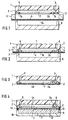
- FIG. 1 depict various stages of the manufacturing process in schematic cross-sectional views.
- a circular body 1 is processed such that a depression 7 and openings for an inlet 5 and an outlet 6 are created.
- a membrane 4 is stretched over a frame 3.
- a member 2 is cut from a foil in accordance with the contour of the depression 7 such that the member 2 completely covers the inner edge 7a of the depression 7 and so that at one place 2a bulge in the form of a tongue is created.
- the member 2 is placed over the inner edge of the depression 7 so that the bulge 2a is positioned above the opening 6 for the outlet.
- the creation of the depression 7 and of the openings 5 and 6 is typically performed by using precision machining methods, such as CNC-milling, CNC-turning, or micromachining, or the whole body together with the depression 7 is fabricated in one step by injection molding.
- the membrane 4 For manufacturing the membrane 4, it is preferred to use a method as described in DE 3920788. For example, a silicon wafer with a diameter of 100 mm is covered with a separation layer 14 of gold and a polytetrafluoroethylene (PTFE) layer 4 is spin coated. The frame 3 is adhesively bonded to the PTFE, and the PTFE membrane is mechanically separated from the silicon. The gold layer 14 adheres to the PTFE.
- PTFE polytetrafluoroethylene
- the circular body 1 and the membrane 4 consist of polytetrafluoroethylene (PTFE), and the member 2 consists of fluorinated ethylene propylene (FEP).
- PTFE polytetrafluoroethylene
- FEP fluorinated ethylene propylene
- the outer diameter of the body 1 is 42 mm
- the depression 7 has a depth of 300 micrometers
- the membrane has a thickness of 5 micrometers
- the inner diameter of the frame 3 is 42 mm
- the thickness of the member 2 is 25 micrometers.
- not all parts are drawn to scale. In particular, the membrane 4 and the parts 2 or 2a are drawn somewhat thicker than other parts to show them more clearly.
- the membrane 4, together with the frame 3, is positioned above the body 1 such that the membrane 4 is located upon the member 2.
- the frame 3 lies closely at the outer circumference of the body 1.
- the membrane 4 is then pressed on the member 2 by means of a heating device (thermode) 8 and heated for such a time interval that the member 2 is starting to melt.
- the body 1 and the membrane 4 are also getting warm. However, the small spacing between the frame 3 and the part of the body 1 which was also heated, prevents an expansion of the body 1. If the thermal expansion of the body 1 is not prevented, deformations and distortions in the joined parts, caused by differences in the thermal coefficient of expansion, will result after joining and cooling down.
- the temperature during local heating is 352 degrees centigrade.
- the membrane 4 is brought into contact with the body 1 with the side which is distal to the separation layer 14 of gold.
- the separation layer 14 facilitates the removing of the thermode 8 from the membrane after bonding. After bonding, the separation layer 14 is removed from the membrane by etching in a suitable solution.
- the membrane 4 is bonded to the body 1 while the membrane is fixed to a frame 3.
- a thin membrane tends to bend and to roll up which hampers bonding the membrane 4a stretched on the body 1.
- the membrane 4 is thicker than about 100 micrometers, it is possible to bond it to the body 1 without the use of a frame (see Figure 5).
- the membrane 4 does not need to extend over the entire body 1, but it is possible to bond it to a part of the body, and it is possible to bond the membrane 4 to a part of the body 1 where there is no depression 7.
- Figures 5 and 6 serve to illustrate the joining steps a) to c) of the invention by using special joining parts.
- Figure 6 shows how it is possible to bond a second body 4 instead of a membrane to the body 1.
- the body 4 has a thin brim 4b at which the thermode 8 is pressing the body 4 against the body 1 and where the bonding takes place.
- the thickness of the brim 4b is in the range of a few micrometers to 1 mm. Preferably, the thickness is less than 100 micrometers.
- the member 2 is cut according to the shape of the bonding area, but it is also possible to extend the member 2 over that area as shown in Figure 6 by the example of the part 2b and in Figure 1 to 4 by the example of the part 2a.
- the thermode 8 is made of copper which is electrically heated.
- the copper surface of the thermode can be nickel-plated in order to prevent corrosion and adherence of the membrane.
- the temperature of the thermode is optimized such that a stable connection is achieved between the membrane 4 and the body 1, but that the time during which heat is applied is kept small. In that way, a deformation of the body 1 is substantially avoided.
- the heating time may be, for example, as short as 15 seconds.
- the parts of the thermode which come into contact with the membrane protrude from the surface of the thermode and have a shape adapted to the portion where the connection actually has to be made.
- thermode 8 which is hollow, e.g. a hollow cylinder for the bonding of a membrane 4 to a body along a circular path as shown in Figure 5.
- the parts 8a of the thermode 8 which come into contact with the membrane 4 or the body 1 can be designed as a protruding pattern with a shape adapted to the path along which the bonding shall take place.
- the protruding pattern is preferably produced by milling and drilling or by micromachining of the thermode 8.
- Figure 5 also shows that the body 1 can be hindered from expanding during heating of the member 2 by a holder 15 which is separated from the frame 3 and which can have protruding parts 15a which are inserted into depressions in the body 1.
- Figure 4 illustrates additional steps for manufacturing the final degasser.
- a piece of a gas-permeable layer 12 and a glass frit 9 acting as a supporting structure are arranged and then mounted using a cover 10.
- the frit 9 everywhere projects beyond the edge 7a of the depression 7, so that there is no danger that the membrane 4a is damaged at its edge by the frit 9. Without such a measure, the thin membrane (typically 5 micrometers thick) can easily be damaged, because the body 1 which is typically made of PTFE, can easily deform locally and the frit 9 may be pushed through the membrane 4a.
- the cover 10 is connected via a seal 13 in a gas-tight manner with the body 1.
- An opening 11 is provided to which a vacuum pump (not shown) can be connected for evacuating the volume within the cover to a residual pressure of about 100 hPa. Due to the underpressure within the space formed by the cover 10 and the membrane 4a, the membrane 4a is sucked against the frit 9.
- the gas-permeable layer 12 prevents that the thin membrane 4a is damaged by the pores of the frit 9.
- the inlet 5 is connected to a solvent supply and the outlet 6 is connected to the high pressure pump of the chromatograph.
- the member 2 can be made of another fluorinated material which becomes soft under temperature increase, such as perfluoro alcoxy (PFA), or the body 1 and the membrane 4 can be made of FEP or PFA.
- PFA perfluoro alcoxy
Landscapes
- Engineering & Computer Science (AREA)
- Mechanical Engineering (AREA)
- Chemical & Material Sciences (AREA)
- Chemical Kinetics & Catalysis (AREA)
- Manufacturing & Machinery (AREA)
- Separation Using Semi-Permeable Membranes (AREA)
Description
- The invention relates to a method for joining two or more solid parts according to
claim 1. Such a method can be used, for example, in the manufacture of a degasser for a liquid chromatograph for joining a gas-permeable membrane to a body receiving the liquid to be degassed. - In liquid chromatography, degassers are used to reduce the amount of gas dissolved in the solvents used. The solvents used in liquid chromatography are usually stored in contact with the surrounding air so that they are usually in a gas-saturated state. These dissolved gases adversely affect the chromatographic measurements.
- US Patent No. 4,469,495 describes a liquid chromatography degasser for removing oxygen or other dissolved gases from a liquid used in liquid chromatography, wherein the liquid being degassed is passed through a spiral-shaped tube. This tube is made of a synthetic resin material, such as tetrafluoroethylene. US Patent No. 4,729,773 describes a device for degassing liquids in which the liquid is passed through a tube made of a fluor-resin which allows gases to pass through it while preventing the liquid from doing so. Degassers using flat membranes are known from US Patent No. 3,751,879 and from US Patent No. 3,735,562. Another degasser using a membrane is known from EP 718016. US Patent No. 3,619,323 describes a method of bonding cured silicone materials to cured silicone materials suitable for implantation within a human body to fabricate an envelope or membrane for an artificial human organ. US Patent No. 4,238,207 describes a method of mounting a filter membrane.
- Degassers using membranes typically comprise a cavity formed in a housing, through which the liquid to be degassed flows. On the side of the membrane distal from the cavity, vacuum is applied, thus forcing gases dissolved in the liquid through the membrane to the outside. The membrane has to be attached to the housing such that liquid cannot leak from the cavity to the outside through the connection between the membrane and the housing. A typical, cost-efficient method for joining the membrane and the housing is glueing.
- Glueing, however, has several disadvantages. First, the glue or bonding agent may be dissolved by certain solvents used in chromatography, thus leading to leaks or complete destruction of the connection. Second, the glueing material may release unwanted substances which may be transported by the solvent stream in a liquid chromatograph to the detector where they interfere with the detection of the sample substances. Third, one of the parts may be damaged, if an under pressure is applied to the cavity.
- The problems mentioned in connection with a degasser can also occur with other parts in a liquid chromatograph which comprise a connection of two parts which come into contact with liquid, for example with solvent.
- In view of the prior art, it is an object of the invention to provide a method for permanently joining solid parts in such a way that the region where the two parts are joined does not release unwanted substances when liquid comes into contact with said region, nor that the connection gets loose. Said parts form a cavity with at least one opening said opening being suitable to be closed in a valve-like function.
- It is another object of the invention to provide a method for joining solid parts in a component of a liquid chromatograph which comes into contact with liquids.
- It is a further object to provide such a method for manufacturing a liquid chromatography degasser which can be performed in a process that is both economical and efficient.
- It is a still further object to provide a method for joining solid parts which is cost efficient.
- According to the present invention, these objects are achieved by a method for joining two or more solid parts, employable in the manufacture of a liquid chromatography degasser, comprising the following steps:
- a) providing a foil between the two or more parts, said parts forming a cavity (7) with at least one opening (6);
- b) heating said foil to an elevated temperature such that-it becomes soft ;
- c) providing a cooling step for cooling down the foil below the elevated temperature of step b);
- d) wherein the foil (2) is cut in such a way that it comprises a tongue (2a) projecting into said cavity (7) and being suitable for closing one of said at least one openings (6) of the cavity (7) in a valve-like function.
-
- The foil arranged between the two parts which are to be joined acts as a welding foil which is heated and then, after cooling down, provides for a permanent connection between the two parts. Preferably, the foil is locally heated to a temperature above the melting point. Preferably, at least one of the parts to be joined is prevented from thermal expansion during application of heat, for example by using a framing member surrounding the part.
- According to an embodiment of the invention, one of the two joining partners is a thin membrane which may be as thin as 10 micrometers or thinner. This is particularly useful for manufacturing a liquid chromatography degasser comprising a thin gas-permeable membrane. A degasser which is preferably manufactured according to the method of the present invention is described in the European patent application EP-0 973 031-A entitled Apparatus for Degassing Liquids, filed on the same date and by the same applicant as the present application. The membrane can be made of a fluorinated synthetic material. In an embodiment of the invention, the membrane is stretched across a frame and then placed on the foil by corresponding movement of the frame. The frame may also provide the function of preventing thermal expansion of the body to which the membrane is connected. This embodiment thus provides a method for joining a thin membrane to a body by thermal welding, even though the material of body would be unstable at the used temperatures.
- According to another aspect of the invention, one of the joining partners has a brim at least at one of its edges which is brought into contact with a thermode and pressed against the other joining partner. In this way, for example the housings of pressure transducers can be bonded to each other.
It is understood that the method of the invention can be used in a variety of applications. For example, it can be used for manufacturing lab-on-a-chip devices, wherein capillary structures are produced in a carrier substrate and a foil is attached to the carrier substrate with the method of the invention. The channel structures thus formed in the substrate, which is preferably made of a solvent resistant material, can be used for chemical analysis of fluids in the channels. Furthermore, the method of the invention can be used for joining foils, for example a polyether etherketone (PEEK) foil with another PEEK foil. Also, the method of the invention can be used to connect valve membranes to a corresponding valve housing or valve seat. - Examples of possible materials for the membrane are polyetheretherketone (PEEK) or polytetrafluoroethylene (PTFE), and the material of the housing may comprise PEEK or perfluoro alcoxy (PFA) or fluorinated ethylene propylene (FEP).
- In the following, embodiments of the invention will be explained in detail with reference to the drawings.
- Figure 1
- illustrates a first process step of an embodiment of the invention.
- Figure 2
- illustrates a second process step of an embodiment of the invention.
- Figure 3
- illustrates the result of the process steps according to Figures 1 and 2.
- Figure 4
- schematically shows a degasser for a liquid chromatograph manufactured by employing the method of the invention.
- Figure 5
- illustrates the use of a hollow thermode and a holder.
- Figure 6
- illustrates the use of a second body instead of a membrane and the use of a thermode having parts with a protruding pattern.
- In the following three embodiments of the invention which will be described with reference to Figures 1-4, 5, and 6, respectively, the same reference numerals will be used for parts which have the same function, respectively, e.g., the means for applying heat (thermode) to the parts will be designated with the same reference numeral in all embodiments, as well as the foil used for joining the two parts, etc. .
- In the first embodiment, the joining of a body with a membrane is described. Such an arrangement is used, for example, for producing degassers for liquid chromatographs. Figures 1 and 2 depict various stages of the manufacturing process in schematic cross-sectional views.
- According to Figure 1, a
circular body 1 is processed such that adepression 7 and openings for aninlet 5 and anoutlet 6 are created. Amembrane 4 is stretched over aframe 3. Amember 2 is cut from a foil in accordance with the contour of thedepression 7 such that themember 2 completely covers theinner edge 7a of thedepression 7 and so that at oneplace 2a bulge in the form of a tongue is created. Themember 2 is placed over the inner edge of thedepression 7 so that thebulge 2a is positioned above theopening 6 for the outlet. The creation of thedepression 7 and of theopenings depression 7 is fabricated in one step by injection molding. For manufacturing themembrane 4, it is preferred to use a method as described in DE 3920788. For example, a silicon wafer with a diameter of 100 mm is covered with aseparation layer 14 of gold and a polytetrafluoroethylene (PTFE)layer 4 is spin coated. Theframe 3 is adhesively bonded to the PTFE, and the PTFE membrane is mechanically separated from the silicon. Thegold layer 14 adheres to the PTFE. - In accordance with an embodiment of the invention, the
circular body 1 and themembrane 4 consist of polytetrafluoroethylene (PTFE), and themember 2 consists of fluorinated ethylene propylene (FEP). In a practical example of the invention, the outer diameter of thebody 1 is 42 mm, thedepression 7 has a depth of 300 micrometers, the membrane has a thickness of 5 micrometers, the inner diameter of theframe 3 is 42 mm, and the thickness of themember 2 is 25 micrometers. In the drawings, not all parts are drawn to scale. In particular, themembrane 4 and theparts - The
membrane 4, together with theframe 3, is positioned above thebody 1 such that themembrane 4 is located upon themember 2. Theframe 3 lies closely at the outer circumference of thebody 1. Themembrane 4 is then pressed on themember 2 by means of a heating device (thermode) 8 and heated for such a time interval that themember 2 is starting to melt. - When locally heating the
FEP member 2, thebody 1 and themembrane 4 are also getting warm. However, the small spacing between theframe 3 and the part of thebody 1 which was also heated, prevents an expansion of thebody 1. If the thermal expansion of thebody 1 is not prevented, deformations and distortions in the joined parts, caused by differences in the thermal coefficient of expansion, will result after joining and cooling down. - According to a practical example, in particular when the material of one of the joining partners is PTFE and the
member 2 is made of FEP, the temperature during local heating is 352 degrees centigrade. - When the
FEP part 2 has cooled down, a permanent connection between themembrane 4 and thebody 1 results which is provided by the FEP which has solidified again. Themembrane 4 is then cut through along the connecting line, and theframe 3 together with the rests of the membrane are removed, such that the depression in thebody 1 is sealed by amembrane 4a. The result is shown in Figure 3. In that way, a stable connection between thebody 1 and themembrane 4 is established which is gas-tight. The material of thefoil 2 can be selected such that it is chemically resistant against the liquids used, for example solvents typically used in liquid chromatography. - The
membrane 4 is brought into contact with thebody 1 with the side which is distal to theseparation layer 14 of gold. Theseparation layer 14 facilitates the removing of thethermode 8 from the membrane after bonding. After bonding, theseparation layer 14 is removed from the membrane by etching in a suitable solution. - According to an embodiment of the invention, the
membrane 4 is bonded to thebody 1 while the membrane is fixed to aframe 3. Such an arrangement is preferred because a thin membrane tends to bend and to roll up which hampers bonding themembrane 4a stretched on thebody 1. If themembrane 4 is thicker than about 100 micrometers, it is possible to bond it to thebody 1 without the use of a frame (see Figure 5). Moreover, themembrane 4 does not need to extend over theentire body 1, but it is possible to bond it to a part of the body, and it is possible to bond themembrane 4 to a part of thebody 1 where there is nodepression 7. - Figures 5 and 6 serve to illustrate the joining steps a) to c) of the invention by using special joining parts.
- Figure 6 shows how it is possible to bond a
second body 4 instead of a membrane to thebody 1. Thebody 4 has athin brim 4b at which thethermode 8 is pressing thebody 4 against thebody 1 and where the bonding takes place. The thickness of thebrim 4b is in the range of a few micrometers to 1 mm. Preferably, the thickness is less than 100 micrometers. - In an embodiment of the invention, the
member 2 is cut according to the shape of the bonding area, but it is also possible to extend themember 2 over that area as shown in Figure 6 by the example of thepart 2b and in Figure 1 to 4 by the example of thepart 2a. - According to an embodiment of the invention, the
thermode 8 is made of copper which is electrically heated. The copper surface of the thermode can be nickel-plated in order to prevent corrosion and adherence of the membrane. Preferably, the temperature of the thermode is optimized such that a stable connection is achieved between themembrane 4 and thebody 1, but that the time during which heat is applied is kept small. In that way, a deformation of thebody 1 is substantially avoided. The heating time may be, for example, as short as 15 seconds. The parts of the thermode which come into contact with the membrane protrude from the surface of the thermode and have a shape adapted to the portion where the connection actually has to be made. - It is possible to use a
thermode 8 which is hollow, e.g. a hollow cylinder for the bonding of amembrane 4 to a body along a circular path as shown in Figure 5. As shown in Figure 6, the parts 8a of thethermode 8 which come into contact with themembrane 4 or thebody 1 can be designed as a protruding pattern with a shape adapted to the path along which the bonding shall take place. The protruding pattern is preferably produced by milling and drilling or by micromachining of thethermode 8. - Figure 5 also shows that the
body 1 can be hindered from expanding during heating of themember 2 by aholder 15 which is separated from theframe 3 and which can have protrudingparts 15a which are inserted into depressions in thebody 1. - Figure 4 illustrates additional steps for manufacturing the final degasser. On the side of the
membrane 4a opposite to thebody 1, a piece of a gas-permeable layer 12 and a glass frit 9 acting as a supporting structure are arranged and then mounted using acover 10. The frit 9 everywhere projects beyond theedge 7a of thedepression 7, so that there is no danger that themembrane 4a is damaged at its edge by the frit 9. Without such a measure, the thin membrane (typically 5 micrometers thick) can easily be damaged, because thebody 1 which is typically made of PTFE, can easily deform locally and the frit 9 may be pushed through themembrane 4a. - The
cover 10 is connected via aseal 13 in a gas-tight manner with thebody 1. Anopening 11 is provided to which a vacuum pump (not shown) can be connected for evacuating the volume within the cover to a residual pressure of about 100 hPa. Due to the underpressure within the space formed by thecover 10 and themembrane 4a, themembrane 4a is sucked against the frit 9. The gas-permeable layer 12 prevents that thethin membrane 4a is damaged by the pores of the frit 9. - For using the degasser of the invention in connection with a liquid chromatograph, the
inlet 5 is connected to a solvent supply and theoutlet 6 is connected to the high pressure pump of the chromatograph. - When the vacuum pump connected to the
opening 11 is switched off and the space formed by thecover 10 and themembrane 4a is ventilated with air , while the liquid chromatograph pump continues pumping e.g. methanol through thespace 7, an underpressure is created relative to the space formed by thecover 10 and themembrane 4a. This underpressure sucks themembrane 4a in the direction of theoutlet 6 and would lead to damage of themembrane 4a, if thebulge 2a of theFEP member 2 would not also be sucked to theoutlet 6 and close the outlet. In that way, it is avoided that a greater pressure difference across themembrane 4a is created which would otherwise lead to damage of the membrane.
It is even more likely that an underpressure in thespace 7 will be generated when the chromatograph including the vacuum pump is switched off and the solvent supply is stored at a lower level than the degasser. In this case, thebulge 2a at the inlet of the degasser will prevent themembrane 4a to be damaged by the underpressure. - It is possible to use other materials than those mentioned above for the parts to be joined 1 and 4, respectively, and the
member 2. The materials are chosen such that an adhesion is achieved after the bonding process described here. For example, themember 2 can be made of another fluorinated material which becomes soft under temperature increase, such as perfluoro alcoxy (PFA), or thebody 1 and themembrane 4 can be made of FEP or PFA.
Claims (15)
- A method for joining two or more solid parts, employable in the manufacture of a liquid chromatography degasser, comprising the following steps:wherein the foil (2) is cut in such a way that it comprises a tongue (2a) projecting into said cavity (7) and being suitable for closing one of said at least one openings (6) of the cavity (7) in a valve-like function after joining steps a)-c).a) providing a foil (2) between the two or more parts (1 and 4), said parts forming a cavity (7) with at least one opening (6);b) heating said foil (2) to an elevated temperature such that it becomes soft thereby forming a connection between said two or more parts at a desired joining area ;c) providing a cooling step for cooling down the foil (2) below the elevated temperature of step b);
- Method as in claim 1, wherein, prior to step a), the foil (2) is shaped according to a desired joining area between the two solid parts (1 and 4).
- Method as in claims 1 or 2, wherein at least one of the two parts is a membrane (4).
- Method as in any of the preceding claims, wherein step b) comprises heating of the two parts (1 , 4) only locally.
- Method as in claim 4, wherein the membrane (4) is fixed to a frame (3) and then, prior to step b), pressed on the foil (2) together with the other part (1) to which it is to be connected by means of a thermode (8), and wherein the thermode (8) provides the heat for performing step b).
- Method as in claim 5, wherein the thermode (8) is shaped according to a desired joining area between the two solid parts (1 and 4).
- Method as in claim 5 or 6, wherein the membrane (4) is covered with a separation layer (14) on the side opposite to the foil (2).
- Method as in any of the preceding claims, wherein the first part (1) and/or the second part (4) are prevented from thermal expansion during the heating of the foil (2).
- Method as in claim 8, wherein the prevention of a thermal expansion of the first part (1) and/or of the second part (4) is performed by providing a framing member around said parts.
- Method as in claims 5 and 9, wherein said framing member is the frame (3) to which the membrane (4) is fixed.
- Method as in any of the preceding claims, wherein the foil (2) has a thickness of less than 1000 micrometers, preferably less than 25 micrometers.
- Method as in any of the preceding claims, wherein the foil (2) is made of a fluorinated synthetic material.
- Method as in any of the claims 3 to 10, wherein the membrane (4) has a thickness of less than 10 micrometers.
- Method as in any of the claims 3 to 11, wherein the membrane (4) is made of a fluorinated synthetic material.
- Method as in any of the preceding claims, employed in the manufacture of a liquid chromatography degasser.
Priority Applications (3)
| Application Number | Priority Date | Filing Date | Title |
|---|---|---|---|
| DE1998626454 DE69826454T2 (en) | 1998-07-17 | 1998-07-17 | Method for connecting two or more parts |
| EP19980113376 EP0974390B1 (en) | 1998-07-17 | 1998-07-17 | Method of joining two or more parts |
| US09/353,868 US6355134B1 (en) | 1998-07-17 | 1999-07-15 | Method of joining two or more parts |
Applications Claiming Priority (1)
| Application Number | Priority Date | Filing Date | Title |
|---|---|---|---|
| EP19980113376 EP0974390B1 (en) | 1998-07-17 | 1998-07-17 | Method of joining two or more parts |
Publications (2)
| Publication Number | Publication Date |
|---|---|
| EP0974390A1 EP0974390A1 (en) | 2000-01-26 |
| EP0974390B1 true EP0974390B1 (en) | 2004-09-22 |
Family
ID=8232297
Family Applications (1)
| Application Number | Title | Priority Date | Filing Date |
|---|---|---|---|
| EP19980113376 Expired - Lifetime EP0974390B1 (en) | 1998-07-17 | 1998-07-17 | Method of joining two or more parts |
Country Status (3)
| Country | Link |
|---|---|
| US (1) | US6355134B1 (en) |
| EP (1) | EP0974390B1 (en) |
| DE (1) | DE69826454T2 (en) |
Families Citing this family (4)
| Publication number | Priority date | Publication date | Assignee | Title |
|---|---|---|---|---|
| US7022157B2 (en) * | 2003-11-12 | 2006-04-04 | Agilent Technologies, Inc. | Devices and methods for performing array based assays |
| US9393766B2 (en) * | 2011-05-09 | 2016-07-19 | Boehringer Ingelheim Microparts Gmbh | Process for joining a foil or a membrane |
| JP7184651B2 (en) * | 2016-06-29 | 2022-12-06 | ミルテニー バイオテック ベー.フェー. ウント コー. カー・ゲー | Multi-layer disposable cartridge for biological samples |
| US10946332B2 (en) * | 2017-11-17 | 2021-03-16 | Split Rock Filter Systems Llc | Open channel diffusiophoretic water filtration device and method |
Citations (1)
| Publication number | Priority date | Publication date | Assignee | Title |
|---|---|---|---|---|
| WO1999006135A1 (en) * | 1997-07-31 | 1999-02-11 | Sartorius Ag | Plastic filtration unit and method for producing the same |
Family Cites Families (10)
| Publication number | Priority date | Publication date | Assignee | Title |
|---|---|---|---|---|
| US3883383A (en) * | 1966-09-21 | 1975-05-13 | Ionics | Method of fabricating embossed membranes |
| US3619323A (en) * | 1968-11-06 | 1971-11-09 | Dow Corning | Method of bonding silicones to silicones |
| US4152188A (en) * | 1973-05-25 | 1979-05-01 | Saint-Gobain Industries | Method and apparatus for manufacture of laminated glazing |
| US4211594A (en) * | 1975-11-05 | 1980-07-08 | Sigri Elektrographit Gesellschaft Mit Beschrankter Haftung | Joining together shaped bodies of polytetrafluoroethylene |
| US4165248A (en) * | 1976-12-01 | 1979-08-21 | Ppg Industries, Inc. | Method of joining fluorocarbon membrane sheets with quaternary ammonium compounds |
| US4238207A (en) * | 1979-01-11 | 1980-12-09 | Baxter Travenol Laboratories, Inc. | Method of mounting a filter membrane |
| GB2179289B (en) * | 1984-10-16 | 1988-07-20 | Rast Pty Ltd W | Pads for absorbing pressure shocks and method of manufacture thereof |
| US5364597A (en) * | 1991-03-13 | 1994-11-15 | Cytyc Corporation | Apparatus for collection and transfer of particles |
| ATE175625T1 (en) * | 1993-06-11 | 1999-01-15 | Isovolta | METHOD FOR PRODUCING PHOTOVOLTAIC MODULES AND A DEVICE FOR IMPLEMENTING THIS METHOD |
| US5798187A (en) * | 1996-09-27 | 1998-08-25 | The Regents Of The University Of California | Fuel cell with metal screen flow-field |
-
1998
- 1998-07-17 EP EP19980113376 patent/EP0974390B1/en not_active Expired - Lifetime
- 1998-07-17 DE DE1998626454 patent/DE69826454T2/en not_active Expired - Fee Related
-
1999
- 1999-07-15 US US09/353,868 patent/US6355134B1/en not_active Expired - Fee Related
Patent Citations (1)
| Publication number | Priority date | Publication date | Assignee | Title |
|---|---|---|---|---|
| WO1999006135A1 (en) * | 1997-07-31 | 1999-02-11 | Sartorius Ag | Plastic filtration unit and method for producing the same |
Also Published As
| Publication number | Publication date |
|---|---|
| EP0974390A1 (en) | 2000-01-26 |
| DE69826454D1 (en) | 2004-10-28 |
| US6355134B1 (en) | 2002-03-12 |
| DE69826454T2 (en) | 2005-09-29 |
Similar Documents
| Publication | Publication Date | Title |
|---|---|---|
| JP4515691B2 (en) | Film deaeration system | |
| EP0973031A1 (en) | Apparatus for degassing liquids | |
| US6158712A (en) | Multilayer integrated assembly having an integral microminiature valve | |
| US7665303B2 (en) | Method of segregating a bolus of fluid using a pneumatic actuator in a fluid handling circuit | |
| US7121402B2 (en) | Container hermetically sealed with crushable material and reactive multilayer material | |
| US7624643B2 (en) | Method and apparatus for forming a reference pressure within a chamber of a capacitance sensor | |
| JP2000101019A (en) | Wafer bonding and sealing systems and methods | |
| FI122170B (en) | Hydrogen separation membrane | |
| US7811451B2 (en) | Separation column and liquid chromatograph using the same | |
| JP4341947B2 (en) | Separation membrane module | |
| US6355134B1 (en) | Method of joining two or more parts | |
| CN102803126A (en) | Method for plugging a hole and a plugged hole | |
| US4442324A (en) | Encapsulated backplate for electret transducers | |
| JP2009526640A (en) | Membrane structure for gas separation | |
| JP2007536591A (en) | Electrowetting cell and manufacturing method thereof | |
| EP3020683B1 (en) | Apparatus for manufacturing micro-channel and method for manufacturing micro-channel using same | |
| JP2009518599A (en) | Thin wire joining and / or sealing system and method | |
| AU664905B2 (en) | Method for forming PTFE membrane/gasket assembly | |
| JP2000117835A (en) | Component with a support and a membrane welded to the support, in particular a method for producing a plug for a straw and a membrane-support assembly obtained by the method | |
| JP2001281086A (en) | Pressure sensor and method of manufacturing the same | |
| JP2005017172A (en) | Film sample fixing method, gas cell, and gas permeability measuring device | |
| CN100409421C (en) | Method of securing a sealing object to a base object | |
| US20090214386A1 (en) | Coupling of conduits with melted and solidified plastic material | |
| JP7850584B2 (en) | Explosion-proof gas sensor filter and method for manufacturing the same | |
| JP2007536592A (en) | Electrowetting cell and method of manufacturing electrowetting cell |
Legal Events
| Date | Code | Title | Description |
|---|---|---|---|
| PUAI | Public reference made under article 153(3) epc to a published international application that has entered the european phase |
Free format text: ORIGINAL CODE: 0009012 |
|
| 17P | Request for examination filed |
Effective date: 19990527 |
|
| AK | Designated contracting states |
Kind code of ref document: A1 Designated state(s): CH DE FR GB LI |
|
| AX | Request for extension of the european patent |
Free format text: AL;LT;LV;MK;RO;SI |
|
| AKX | Designation fees paid |
Free format text: CH DE FR GB LI |
|
| RAP1 | Party data changed (applicant data changed or rights of an application transferred) |
Owner name: FORSCHUNGSZENTRUM KARLSRUHE GMBH Owner name: HEWLETT-PACKARD COMPANY, A DELAWARE CORPORATION |
|
| RAP1 | Party data changed (applicant data changed or rights of an application transferred) |
Owner name: FORSCHUNGSZENTRUM KARLSRUHE GMBH Owner name: AGILENT TECHNOLOGIES, INC. (A DELAWARE CORPORATION |
|
| 17Q | First examination report despatched |
Effective date: 20021220 |
|
| RTI1 | Title (correction) |
Free format text: METHOD OF JOINING TWO OR MORE PARTS |
|
| RTI1 | Title (correction) |
Free format text: METHOD OF JOINING TWO OR MORE PARTS |
|
| GRAP | Despatch of communication of intention to grant a patent |
Free format text: ORIGINAL CODE: EPIDOSNIGR1 |
|
| GRAS | Grant fee paid |
Free format text: ORIGINAL CODE: EPIDOSNIGR3 |
|
| GRAA | (expected) grant |
Free format text: ORIGINAL CODE: 0009210 |
|
| AK | Designated contracting states |
Kind code of ref document: B1 Designated state(s): CH DE FR GB LI |
|
| PG25 | Lapsed in a contracting state [announced via postgrant information from national office to epo] |
Ref country code: LI Free format text: LAPSE BECAUSE OF FAILURE TO SUBMIT A TRANSLATION OF THE DESCRIPTION OR TO PAY THE FEE WITHIN THE PRESCRIBED TIME-LIMIT Effective date: 20040922 Ref country code: CH Free format text: LAPSE BECAUSE OF FAILURE TO SUBMIT A TRANSLATION OF THE DESCRIPTION OR TO PAY THE FEE WITHIN THE PRESCRIBED TIME-LIMIT Effective date: 20040922 |
|
| REG | Reference to a national code |
Ref country code: GB Ref legal event code: FG4D |
|
| REG | Reference to a national code |
Ref country code: CH Ref legal event code: EP |
|
| REF | Corresponds to: |
Ref document number: 69826454 Country of ref document: DE Date of ref document: 20041028 Kind code of ref document: P |
|
| REG | Reference to a national code |
Ref country code: CH Ref legal event code: PL |
|
| ET | Fr: translation filed | ||
| PLBE | No opposition filed within time limit |
Free format text: ORIGINAL CODE: 0009261 |
|
| STAA | Information on the status of an ep patent application or granted ep patent |
Free format text: STATUS: NO OPPOSITION FILED WITHIN TIME LIMIT |
|
| 26N | No opposition filed |
Effective date: 20050623 |
|
| PGFP | Annual fee paid to national office [announced via postgrant information from national office to epo] |
Ref country code: FR Payment date: 20080718 Year of fee payment: 11 |
|
| PGFP | Annual fee paid to national office [announced via postgrant information from national office to epo] |
Ref country code: GB Payment date: 20090715 Year of fee payment: 12 Ref country code: DE Payment date: 20090709 Year of fee payment: 12 |
|
| REG | Reference to a national code |
Ref country code: FR Ref legal event code: ST Effective date: 20100331 |
|
| PG25 | Lapsed in a contracting state [announced via postgrant information from national office to epo] |
Ref country code: FR Free format text: LAPSE BECAUSE OF NON-PAYMENT OF DUE FEES Effective date: 20090731 |
|
| GBPC | Gb: european patent ceased through non-payment of renewal fee |
Effective date: 20100717 |
|
| PG25 | Lapsed in a contracting state [announced via postgrant information from national office to epo] |
Ref country code: DE Free format text: LAPSE BECAUSE OF NON-PAYMENT OF DUE FEES Effective date: 20110201 |
|
| REG | Reference to a national code |
Ref country code: DE Ref legal event code: R119 Ref document number: 69826454 Country of ref document: DE Effective date: 20110201 |
|
| PG25 | Lapsed in a contracting state [announced via postgrant information from national office to epo] |
Ref country code: GB Free format text: LAPSE BECAUSE OF NON-PAYMENT OF DUE FEES Effective date: 20100717 |