EP0973127A2 - IC card, IC card processing system, and IC card processing method - Google Patents
IC card, IC card processing system, and IC card processing method Download PDFInfo
- Publication number
- EP0973127A2 EP0973127A2 EP99113730A EP99113730A EP0973127A2 EP 0973127 A2 EP0973127 A2 EP 0973127A2 EP 99113730 A EP99113730 A EP 99113730A EP 99113730 A EP99113730 A EP 99113730A EP 0973127 A2 EP0973127 A2 EP 0973127A2
- Authority
- EP
- European Patent Office
- Prior art keywords
- file
- definition information
- delete
- data
- command
- Prior art date
- Legal status (The legal status is an assumption and is not a legal conclusion. Google has not performed a legal analysis and makes no representation as to the accuracy of the status listed.)
- Granted
Links
Images


Classifications
-
- G—PHYSICS
- G07—CHECKING-DEVICES
- G07F—COIN-FREED OR LIKE APPARATUS
- G07F7/00—Mechanisms actuated by objects other than coins to free or to actuate vending, hiring, coin or paper currency dispensing or refunding apparatus
- G07F7/08—Mechanisms actuated by objects other than coins to free or to actuate vending, hiring, coin or paper currency dispensing or refunding apparatus by coded identity card or credit card or other personal identification means
- G07F7/10—Mechanisms actuated by objects other than coins to free or to actuate vending, hiring, coin or paper currency dispensing or refunding apparatus by coded identity card or credit card or other personal identification means together with a coded signal, e.g. in the form of personal identification information, like personal identification number [PIN] or biometric data
- G07F7/1008—Active credit-cards provided with means to personalise their use, e.g. with PIN-introduction/comparison system
-
- G—PHYSICS
- G06—COMPUTING; CALCULATING OR COUNTING
- G06Q—INFORMATION AND COMMUNICATION TECHNOLOGY [ICT] SPECIALLY ADAPTED FOR ADMINISTRATIVE, COMMERCIAL, FINANCIAL, MANAGERIAL OR SUPERVISORY PURPOSES; SYSTEMS OR METHODS SPECIALLY ADAPTED FOR ADMINISTRATIVE, COMMERCIAL, FINANCIAL, MANAGERIAL OR SUPERVISORY PURPOSES, NOT OTHERWISE PROVIDED FOR
- G06Q20/00—Payment architectures, schemes or protocols
- G06Q20/30—Payment architectures, schemes or protocols characterised by the use of specific devices or networks
- G06Q20/34—Payment architectures, schemes or protocols characterised by the use of specific devices or networks using cards, e.g. integrated circuit [IC] cards or magnetic cards
- G06Q20/341—Active cards, i.e. cards including their own processing means, e.g. including an IC or chip
-
- G—PHYSICS
- G06—COMPUTING; CALCULATING OR COUNTING
- G06Q—INFORMATION AND COMMUNICATION TECHNOLOGY [ICT] SPECIALLY ADAPTED FOR ADMINISTRATIVE, COMMERCIAL, FINANCIAL, MANAGERIAL OR SUPERVISORY PURPOSES; SYSTEMS OR METHODS SPECIALLY ADAPTED FOR ADMINISTRATIVE, COMMERCIAL, FINANCIAL, MANAGERIAL OR SUPERVISORY PURPOSES, NOT OTHERWISE PROVIDED FOR
- G06Q20/00—Payment architectures, schemes or protocols
- G06Q20/30—Payment architectures, schemes or protocols characterised by the use of specific devices or networks
- G06Q20/34—Payment architectures, schemes or protocols characterised by the use of specific devices or networks using cards, e.g. integrated circuit [IC] cards or magnetic cards
- G06Q20/357—Cards having a plurality of specified features
- G06Q20/3576—Multiple memory zones on card
Definitions
- the present invention relates to an IC card for receiving a command transmitted from a card reader/writer and executing processing in accordance with the received command.
- the present invention also relates to an IC card processing system including a card reader/writer for transmitting a command to an IC card and the IC card for receiving a command transmitted from the card reader/writer and executing processing in accordance with the received command.
- the present invention relates to an IC card processing method applied to an IC card for receiving a command transmitted from a card reader/writer and executing processing in accordance with the received command.
- This IC card incorporates an IC chip including a nonvolatile memory and control section. Files for executing various applications are stored in the nonvolatile memory.
- the IC card receives a command transmitted from a card reader/writer and executes a predetermined application in accordance with the command. That is, the IC card reads out predetermined files from the nonvolatile memory and executes the predetermined application.
- a new application can be added to the IC card by storing new files in the nonvolatile memory of the IC card through the card reader/writer.
- the present invention has been made to solve the above problem, and has as its object to provide an IC card, IC card processing system, and IC card processing method which can solve the problem of a shortage of memory capacity upon addition of a new application.
- an IC card comprising communication means receiving externally transmitted data, storage means for storing a file and definition information of the file, and delete means for, when the data received through the communication means is a command to delete a predetermined file, deleting the predetermined file and definition information of the predetermined file from the storage means.
- the IC card processing system of the present invention comprises storage means for storing a file and definition information of the file, and delete means for deleting the predetermine file and the definition information of the predetermined file from the storage means.
- an IC card processing method comprising the first step of receiving externally transmitted data and the second step of, when the data received in the first step is a command to delete the predetermined file, deleting the predetermined file and definition information of the predetermined file from the data storage section.
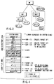
- FIG. 1 is a block diagram showing the schematic arrangement of an IC card processing system of the present invention. As shown in FIG. 1, the IC card processing system includes an IC card 100 and IC card processing apparatus 200.
- the IC card 100 incorporates a control section 110, memory 120, and contact section 130. Of these components, the control section 110 and memory 120 are embedded as IC chips in the card.
- the control section 110 is, for example, a CPU and executes predetermined processing in accordance with the programs stored in a program memory 122 of the memory 120.
- This predetermined processing includes directory delete processing. That is, the control section 110 functions as a delete means and delete control means.
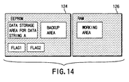
- the memory 120 includes the program memory 122, a data memory 124, and working memory 126.
- the program memory 122 is, for example, a mask ROM. Programs and the like required for execution of predetermined processing by the control section 110 are recorded on the program memory 122. That is, programs required for directory delete processing are also recorded on the program memory 122.
- the data memory 124 (storage means) is, for example, an EEPROM.
- Application files and the like for implementing various applications are stored in the data memory 124. More specifically, definition information for constructing a file structure like the one shown in FIG. 2 is stored in the data memory 124.
- the application files are managed under this file structure.
- the file structure shown in FIG. 2 will be briefly described below.
- DF (dedicated file)1 and DF2 are positioned below MF (main file).
- DF1-1 and EF (elementary file)1-1 are positioned below DF1.
- EF1-1-1 is positioned below DF1-1.
- EF2-1 and EF2-2 are positioned below DF2.
- EF1-1 and EF1-1-1 include application files (ef1-1 and ef1-1-1) for implementing a first application.
- EF2-1 and EF2-2 include application files (ef2-1 and ef2-2) for implementing a second application different from the first application. Note that the relationship between DF and EF corresponds to that between a main file and subfile.
- the working memory 126 is, for example, a RAM. Data to be processed by the control section 110 and the like are temporarily stored in the working memory 126.
- the contact section 130 comes into electric contact with a reader/writer 230 of the IC card processing apparatus 200 to provide data stored in the IC card 100 to the reader/writer 230 or receive data provided from the reader/writer 230.
- the IC card processing apparatus 200 is used as a terminal apparatus in a financial system or shopping system.
- a tabletop type that is installed in a store or a portable type is available.
- the IC card processing apparatus 200 includes a control section 210, memory 220, reader/writer 230, input section 240, and display 250.
- the control section 210 is, for example, a CPU and executes predetermined processing in accordance with the programs stored in the memory 220.
- the predetermined processing includes command generation processing of generating a select command and directory delete command. That is, the control section 210 functions as a command generation means for generating commands.
- Programs required for execution of predetermined processing by the control section 210 are stored in the memory 220.
- Programs required for execution of predetermined processing by the control section 210 are stored in the memory 220.
- a program required to execute command generation processing is stored in the memory 220.
- the reader/writer 230 (communication means) reads out data from the IC card 100 or writes data thereon through the contact section 130.
- the input section 240 receives an input from the operator of the IC card processing apparatus 200.
- the input section 240 receives a size setting (change) for a backup area (to be described later).
- Setting (changing) of a backup area size is designated with respect to the IC card 100 through the reader/writer 230 on the basis of the backup area size setting (change) received by the input section 240.
- the size of the backup area is determined on the basis of this designation. That is, the input section 240 has the function of changing the size of the backup area.
- the display 250 displays, for example, data read out from the IC card 100.
- deleting a predetermined directory DF in FIG. 2
- subdirectories (EF) positioned below the predetermined directory are deleted.
- a command output from the IC card processing apparatus 200 must be received on the IC card 100 side. That is, the IC card 100 must be set in the IC card processing apparatus 200.
- the files in the data memory 124 of the IC card 100 can be accessed through the IC card processing apparatus 200.
- a select command is generated under the control of the control section 210, and the generated select command and file name (DF2) are transmitted from the reader/writer 230 to the contact section 130.
- the contact section 130 receives the select command and file name (DF2)
- the file having the file name (DF2) sent together with the select command is selected from the data memory 124 and a response indicating that the file has been selected is transmitted to the reader/writer 230 through the contact section 130 under the control of the control section 110.
- the control section 110 also recognizes the selected file (DF2) as the current file.
- the control section 210 receives the response corresponding to the previously transmitted select command through the reader/writer 230, and outputs the received response to the display 250.
- a directory delete command is generated under the control of the control section 210, and only the generated directory delete command is transmitted from the reader/writer 230 to the contact section 130.
- the contact section 130 receives only the directory delete command, the current file (DF2 in this case) stored in the data memory 124 is deleted under the control of the control section 110. That is, when the current file (DF2 in this case) is detected, the subfiles (EF2-1 and EF2-2) positioned below the current file are deleted.
- the file (MF in this case) positioned above the deleted current file is recognized as the current file.
- a directory delete command is generated under the control of the control section 210, and the generated directory delete command and file name (DF2) are transmitted from the reader/writer 230 to the contact section 130.
- the contact section 130 receives the directory delete command and file name (DF2), the file having the file name (DF2) sent together with the directory delete command is deleted from the data memory 124 under the control of the control section 110. That is, when the designated file (DF2 in this case) is deleted, the subfiles (EF2-1 and EF2-2 in this case) positioned below the designated file are deleted.
- the directory delete command is a command used to delete a predetermined directory (e.g., DF2, which is assumed as a main file) and the subdirectories (e.g., EF2-1 and EF2-2, which are assumed as subfiles) positioned below the predetermined directory and release the memory area occupied by the deleted directory (including the subdirectories).
- DF2 a predetermined directory
- subdirectories e.g., EF2-1 and EF2-2, which are assumed as subfiles
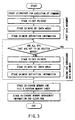
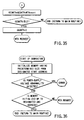
- FIG. 3 is a flow chart showing an outline of directory delete processing using a directory delete command.
- directory delete processing using a directory delete command is implemented by nine stages.
- a stage number (a log of processing such as stage 00) is saved in the backup area (backup-EF or backup-ef in FIGS. 4 to 10) of the data memory 124. More specifically, as processing proceeds, i.e., every time the stage number is updated, the updated stage number is saved in the backup area of the data memory 124.
- Definition information, real data, and the like are also saved in the backup area. More specifically, when definition information and real data are to be relocated, the definition information and real data are saved in the backup area. With this operation, even if directory delete processing is interrupted due to accidental power-down or reset, the directory delete processing can be re-executed after a normal return.
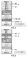
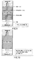
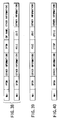
- FIG. 4 is a view for explaining stages 00 and 01 in the flow chart of FIG. 3.
- FIG. 5 is a view for explaining stage 02 in the flow chart of FIG. 3.
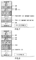
- FIG. 6 is a view for explaining stage 04 in the flow chart of FIG. 3.
- FIG. 7 is a view for explaining stage 81 in the flow chart of FIG. 3.
- FIG. 8 is a view for explaining stage 82 in the flow chart of FIG. 3.
- FIG. 9 is a view for explaining stage 84 in the flow chart of FIG. 3.
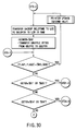
- FIG. 10 is a view for explaining stage 20 in the flow chart of FIG. 3.
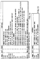
- FIG. 11 shows a list of data names, data sizes (byte counts), and data contents stored in the working area of the working memory 126. Assume that the data shown in FIG. 11 are sequentially stored in this working area in the order of upper addresses.
- FIG. 12 shows a list of data names, data sizes (byte counts), and data contents stored in the backup area of the data memory 124. Assume that the data shown in FIG. 12 are sequentially stored in this backup area in the order of upper addresses.
- FIG. 13 shows a list of data names, data sizes (byte counts), and data contents stored in the system area of the data memory 124.
- the control section 110 Upon recognition of a directory delete command, the control section 110 prepares for execution of the directory delete command. In making one of preparations for this execution, the control section 110 stores address X0R in FIG. 4 in a pointer. Address X0R indicates the start address of the definition information of DF2. The pointer stores the addresses of a delete target file (to be deleted) and other files (ef and the like) and the addresses of the pieces of definition information of the delete target file and other files (DF, EF). The pointer is set in the backup area of the memory 220 (see FIG. 11).
- address X1R indicates the definition information of EF2-1.
- Address X2R indicates the start address of the definition information of EF1-1.
- Address Y2TOP indicates the start address of ef1-1 (application file).
- Address PY2R indicates the start address of part of ef1-1 (application file).
- Address PY1R indicates the start address of part of ef2-1 (application file).
- Address Y0R indicates the start address of backup-ef.
- stage 02 as shown in FIG. 5, ef2-1 is deleted, ef1-1 is moved, and the addresses are updated. Note that ef1-1 is divided and moved (see FIG. 4).
- Stage 04 Movement of EF (Definition Information)
- stage 04 as shown in FIG. 6, DF2 and EF2-1 are deleted upon deletion of ef2-1, DF1-1 and EF1-1 are moved, and the addresses are updated.
- stage 81 the addresses shown in FIG. 7 are stored in the pointer.
- Stage 82 Movement of ef (Execution Data)
- stage 82 as shown in FIG. 8, ef2-2 is deleted, ef1-1-1 is moved, and the addresses are updated. Note that ef1-1-1 is divided and moved.
- Stage 84 Movement of EF (Definition Information)
- stage 04 as shown in FIG. 9, EF2-2 is deleted upon deletion of ef2-2, EF1-1-1 is moved, and the addresses are updated.
- stage 20 as shown in FIG. 10, an available area is initialized (memory area is released). With this operation, a new storage area can be ensured.
- a location like the one shown in FIG. 4 is realized under the control of the control section 110. More specifically, when definition information (DF, EF) is to be stored, the definition information is sequentially located from one end of the storage area of the data memory 124. When read data (ef) is to be stored, the read data is sequentially located from the other end of the storage area of the data memory 124. That is, the control section 110 functions as a location means.
- definition information is sequentially relocated from one end of the storage area under the control of control section 110.
- read data is sequentially relocated from the other end of the storage area under the control of the control section 110. That is, the control section 110 functions as a storage position control means.
- control section 110 controls the storage positions of definition information and real data, as shown in FIGS. 4 to 10.
- address data indicating the locations of the definition information and real data are always managed and backed up in the backup area. Furthermore, these address data are updated upon relocation of definition information and real data and are backed up in the backup area at this update timing.
- the flow chart in FIG. 3 exemplifies the case wherein real data and definition information are alternately deleted and relocated.
- the present invention is not limited to this. For example, after all the real data as delete target data are deleted and other data are relocated, all definition information as delete target information may be deleted and other information may be relocated.
- a data update method will be described in more detail next with reference to FIGS. 14 to 16.
- flags (FLAG1 and FLAG2) assigned to memory cells are used. These flags are used to record a command processing history in preparation for power-down during execution of a command. When power-down occurs during data write, in particular, data cannot be compensated for. Therefore, careful consideration must be given to such operation.
- the flag data When the flag data is $80, the flag represents 1. When the flag data is $00, the flag represents 0. As described above, however, when a drop in power supply voltage or reset occurs during a flag rewrite, you cannot know how the flag data will change. For this reason, with the flag data other than $80, the flag is regarded as 0.
- data is updated by using the two flags and the data backup area. At least the data before the update or the data after the update is compensated by this method.
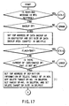
- FIG. 3 Each stage in FIG. 3 will be described in more detail next with reference to the flow charts of FIGS. 17 to 36.
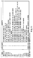
- the following are the contents indicated by the abbreviations in FIGS. 17 to 36:
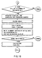
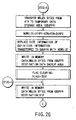
- Stage 00 in the flow chart of FIG. 3 will be described first with reference to the flow charts of FIGS. 17 and 18.
- a received message is a WTX response
- the flow jumps to a WTX response processing routine (STX-1). If the received message is not a WTX response and no data backup EF is present, an error is output. If the received message is not a WTX response and a data backup EF is present, the address (top address) of the data backup EF and the size of the backup area are acquired and stored in the working memory 126 (names: GBUFFEFTOP, GBUFFLC).
- stage number "$01" is stored in the working memory 126 (GSTGR).
- "$01" is set in the working memory 126 (GCONTR: WTX processing counter).
- the data (DELDFSN, DELPFSN, DELFSIZ) in the working memory 126 are stored in the data memory 124 (DELDFSNE, DELPFSNE, DELFSIZE in this order). If a write is not normally performed, an error is output. If the write is normally performed, FLAG0 is set to "$80". The flow then advances to stage 01-0 in the flow chart.
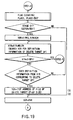
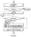
- Stage 01 or 81 in the flow chart of FIG. 3 will be described next with reference to the flow charts of FIGS. 19 and 20.
- the definition information of a delete target DF is used to search for the definition information of a delete target EF toward upper addresses in units of WDLENs. The searched-out address is stored in the working memory 126 (X1R). If no delete target EF is searched out after the available memory area is searched up to the lowest address (DIRP1), the flow jumps to stage 02-3.
- a delete target EF is searched out, a data area for the EF is specified from the definition information of the delete target EF, and the data obtained by adding the EF top address and the EF size is re-stored in the working memory 126 (Y0R).
- the above operation is performed when the stage number in the working memory 126 (GSTGR) is "$01".
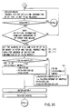
- a search for the definition information of an EF that is not to be deleted is made toward upper addresses, and the corresponding address is stored in the working memory 126 (X2R) (the flow then shifts to "B" in the flow chart). If no EF that is not to be deleted (moved) after the available memory area is searched up to the lowest address (DIRP1), the flow jumps to stage 02-3. If an EF that is not to be deleted is searched out, the data area top address and size of the EF are specified from the definition information of the EF that is not to be deleted.
- the data area top address of the EF that is not to be deleted is stored in the working memory 126 (PY2R), and the size of the EF is stored in the working memory 126 (LCR).
- the data obtained by subtracting the size of the EF that is not to be deleted from the working memory 126 (Y0R) is stored in the working memory 126 (PY1R).
- the working memory 126 LCR
- the data obtained by subtracting the data in the working memory 126 (LCR) from the working memory 126 (Y0R) is stored in the working memory 126 (PY1R), and the data obtained by subtracting the data obtained by adding the top address of the EF that is not to be deleted and the size from the data in the working memory 126 (LCR) is stored in the working memory 126 (PY2R).
- the data are set in the working memory 126 (Y0R, X1R, X2R, PY1R, PY2R, LCR), and the stage number in the working memory 126 (GSTGR) is incremented by one.
- the pointer update routine is then called, and the data in the working memory 126 (GSTGR, Y0R, X1R, X2R, PY1R, PY2R, LCR) are stored in the data memory 124 (GSTGE, Y0E, X1E, X2E, PY1E, PY2E, LCE).
- the flow then jumps to ST02-0 in the flow chart.
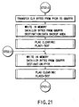
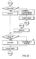
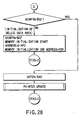
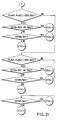
- Stages 02 or 82 in the flow chart of FIG. 3 will be described next with reference to the flow charts of FIGS. 21 and 22.
- stage 02-2 if the data in the working memory 126 (PY2R) does not coincide with the top address of the moved EF, i.e., all the data area for the EF that is not to be deleted are not moved, the backup area size is retained in the working memory 126 (LCR), and the data in the 126 (PY1R, PY2R) are decreased by the backup area size.
- the pointer update routine is then called, and the data (GSTGR, Y0R, X1R, X2R, PY1R, PY2R, LCR) in the working memory 126 are stored in the data memory 124 (GSTGE, Y0E, X1E, X2E, PY1E, PY2E, LCE). The flow jumps to stage 02-2.
- the data in the working memory 126 (PY2R) coincides with the top address of the moved EF, i.e., all the data area for the EF that is not to be deleted are moved, the data in the working memory 126 (Y0R) is changed to the data of the working memory 126 (PY1R). If the stage number in the working memory 126 (GSTGR) is "$81" or $82", the working memory 126 (GSTGR) is set to "$84".
- the data in the working memory 126 (X1R) is set to the sum of the data in the working memory 126 (X0R) and data corresponding to the size (WDLENx2) of the definition information of the delete target directory. As a consequence, the working memory 126 (GSTGR) is set to "$04".
- the pointer update routine is then called to store the data in the working memory 126 (GSTGR, Y0R, X1R, X2R, PY1R, PY2R, LCR) in the data memory 124 (GSTGE, Y0E, X1E, X2E, PY1E, PY2E, LCE). The flow then jumps to stage 04-0.
- stage 02-3 the lowest address (DIRP1) of the available memory area is stored in the working memory 126 (X2R).
- the data in the working memory 126 (Y0R) is changed to the data in the working memory 126 (PY1R). If the stage number in the working memory 126 (GSTGR) is "$81" or "$82", the working memory 126 (GSTGR) is set to "$84".
- the stage number in the working memory 126 is not "$81" or "$82"
- the data in the working memory 126 is set to the sum of the data in the working memory 126 (X0R) and data corresponding to the size (WDLENx2) of the definition information of the delete target directory, and the working memory 126 (GSTGR) is set to "$04".
- the pointer update routine is called to store the data in the working memory 126 (GSTGR, Y0R, X1R, X2R, PY1R, PY2R, LCR) in the data memory 124 (GSTGE, Y0E, X1E, X2E, PY1E, PY2E, LCE). The flow then jumps to stage 04-0.
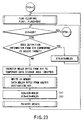
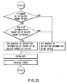
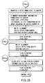
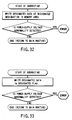
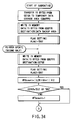
- Stage 04 or 84 in the flow chart in FIG. 3 will be described next with reference to the flow charts of FIGS. 23, 24, and 25.
- the definition information from the address stored in the working memory 126 does not indicate a delete target
- the definition information is transferred to the address stored in the working memory 126 (X0R).
- WDLEN definition information size
- the pointer update routine is called to store the data in the working memory 126 (GSTGR, X0R, Y0R, X1R, X2R, PY1R, PY2R, LCR) in the data memory 124 (GSTGE, X0E, Y0E, X1E, X2E, PY1E, PY2E, LCE). Thereafter, the flow returns to stage 04-0.
- stage 04-1 If it is determined in stage 04-1 that the data in the working memory 126 (X2R) is the lowest address (DIRP1) of the available memory area, the flow jumps to stage 04-2. If the data in the working memory 126 (X2R) is not the lowest address (DIRP1) of the available memory area, the data area top address information of the definition information from the address in the working memory 126 (X2R) is replaced with the data in the working memory 126 (PY1R). The data is then transferred to the address in the working memory 126 (X0R). Data corresponding to the definition information size (WDLEN) is added to the address in the working memory 126 (X0R, X1R), and the working memory 126 (GSTGR) is set to "$81".
- WDLEN definition information size
- the pointer update routine is called to store the data in the working memory 126 (GSTGR, X0R, Y0R, X1R, X2R, PY1R, PY2R, LCR) in the data memory 124 (GSTGE, X0E, Y0E, X1E, X2E, PY1E, PY2E, LCE). Thereafter, the flow jumps to stage 01-0.
- stage 04-2 if the parent DF of the delete target DF is not an MF and the use size information of the parent DF of the delete target DF is not set, the address of the definition information of the parent DF of the delete target DF is set in the working memory 126 (X1R). In other cases, the address of the definition information of the MF is set in the working memory 126 (X1R).
- the stage number in the working memory 126 (GSTGR) is set to "$20".
- the pointer update routine is then called to store the data in the working memory 126 (GSTGR, X0R, Y0R, X1R, X2R, PY1R, PY2R, and LCR) in the data memory 124 (GSTGE, X0E, Y0E, X1E, X2E, PY1E, PY2E, LCE). Thereafter, the flow advances to stage 20-0.
- stage 20-1 the data in the backup area is transferred to the address in the working memory 126 (X1R) (the flow then jumps to "C” in the flow chart).
- the stage number in the working memory 126 (GSTGR) is set to "$40".
- the pointer update routine is called to store the data in the working memory 126 (GSTGR, X0R, Y0R, X1R, X2R, PY1R, PY2R, LCR) in the data memory 124 (GSTGE, X0E, Y0E, X1E, X2E, PY1E, PY2E, LCE). Thereafter, the flow advances to stage 40.
- the lowest address information (DIRP1) of the available memory area of the memory management information is replaced with the data in the working memory 126 (X0R), and the lowest address information (DIRP2) of the data area of the memory management information is replaced with the data in the working memory 126 (Y0R).
- the above data are stored in the backup area.
- stage 40-1 the data in the backup area is stored in the memory management information area.
- stage 40-2 a security status (collation state) acquired from a DF other than an MF is cleared.
- the data in the data memory 124 (DELDFSNE, DELPFSNE, DELFSIZE, GSTGE, X0E, Y0E, X1E, X2E, PY1E, PY2E, LCE) are bitmapped in the working memory 126 (DELDFSN, DELPFSN, DELFSIZ, GSTGR, X0R, Y0R, X1R, X2R, PY1R, PY2R, LCR). "$00" which is the initial value of the WTX processing counter is set in the working memory 126 (GCONTR). The flow then advances to the WTX response processing routine (STX-1).
- designated data is written at a target location designated in the memory area. In this case, if a power supply voltage abnormality is detected, an error is output. If no power supply voltage abnormality is detected, the processing in this subroutine ends.
- designated data is written in a designated flag. In this case, if a power supply voltage abnormality is detected, and an error is output. If no power supply voltage abnormality is detected, the processing in this subroutine ends.
- the data in the working memory 126 (GSTGR, X0R, Y0R, X1R, X2R, PY14, PY2R, LCR) are transferred to the working memory 126 (GBUFFR) and stored in the backup area.
- FLAG1 is set to "$80", and the flow jumps to the pointer update routine (second half).
- the data in the backup area is stored from the address of the data memory 124 (GSTGE).
- FLAG2 is set to "$80". If the data in the working memory 126 (GSTGR) is "$80" or "$82", the data in the working memory 126 (LCR) is multiplied by 64, 1 is added to the resultant data, and the sum is doubled. The resultant data is then added to the data in the working memory 126 (GCONTR). If the stage number in the working memory 126 (GSTGR) is not "$02" or "$82", the data in the working memory 126 (GCONTR) is incremented by one (the flow then jumps to "G” in the flow chart).
- a memory having a predetermined size is initialized from a designated start address. In this case, if a power supply voltage abnormality is detected, and error is output. No power supply voltage abnormality is detected, and the memory is not initialized up to a designated end address, the flow advances to the step of generating a WTX request. If no power supply voltage abnormality is detected, and the memory is initialized to the designated end address, the processing in this subroutine ends.
- flags and execution statuses will be described next with reference to FIG. 37.
- flags FLAG0, FLAG1, FLAG2
- a flag FLAG0
- a flag indicating that processing based on a directory delete command is being executed is rewritten at the beginning and end of the processing.
- the pointer and data area are backed up by using flags (FLAG1, FLAG2) other than this flag (FLAG0).
- "XX" in FIG. 37 represents arbitrary data. Flag data other than the flag data "$80" are handled as "$00".
- a DF sequence number is used to identify a DF and uniquely assigned to each DF.
- This conventional method cannot satisfactorily support a directory delete command. That is, identical sequence numbers are assigned to DFs after repetitive deletion and addition of DFs.
- sequence numbers are managed in the bitmap format to allow addition of 32 DFs other than an MF.
- sequence numbers are managed with 4 bytes (DFSEQNO) of memory management information.
- bitmapped data When, for example, DF sequence number 1, number 4, and number 9 are used, the bitmapped data become:
- the above bitmapped data are created by the control section 110 and stored in the data memory 124. That is, the control section 110 functions as a bitmapped data creation means.
- the data memory 124 functions as a bitmapped data storage means for storing bitmapped data.
- the IC card processing apparatus 200 transmits a command message to the IC card 100.
- the processing designated by the received command is executed in the IC card 100.
- the IC card 100 returns a response indicating the processing result to the IC card processing apparatus 200.
- the IC card 100 and the IC card processing apparatus 200 exchange such a series of messages.
- the IC card 100 Assume that when the IC card 100 receives a command message, command processing corresponding to the received command message requires a period of time longer than a predetermined period of time (BWT). In this case, the IC card 100 returns a WTX request (wait time prolongation request) to the IC card processing apparatus 200. In response to this request, the IC card processing apparatus 200 returns a WTX response (wait time prolongation response) to the IC card 100.
- WTX request wait time prolongation request
- the IC card processing apparatus 200 returns a WTX response (wait time prolongation response) to the IC card 100.
- FIGS. 38 to 40 The abbreviations in FIGS. 38 to 40 will be described first:
- DF definition information (length: WDLENx2) includes wAI, PFSN, (other information), DFSN, (DF name and other information), WAI, DFSN, (other information), FSIZ, USIZ, (other information), FSIZ, USIZ, (other information), and the like.
- MF definition information (length: WDLEN) includes WAI, DFSN, (other information), FSIZ, USIZ, (other information), and the like. Note that the format of this MF definition information is identical to that of the second half of the DF definition information.
- EF definition information includes WAI, DFSN, (other information), EFTOP, EFSIZ, (other information), and the like.
- control section 110 functions as a file access management means. This prevents leakage of the information of a file to which access is restricted through an access key.
- an IC card, IC card processing system, and IC card processing method which can solve the problem of a shortage of memory capacity upon addition of a new application.
Abstract
Description
Claims (19)
- An IC card (100) having an IC chip, characterized by comprising:communication means (130) for receiving externally transmitted data;storage means (120, 124) for storing a file and definition information of the file; anddelete means (110) for, when the data received through said communication means is a command to delete a predetermined file, deleting the predetermined file and definition information of the predetermined file from said storage means.
- An IC card according to claim 1, characterized in that said storage means (120, 124) includes a storage area (120, 124) for storing a main file, a subfile positioned below the main file, definition information of the main file, and definition information of the subfile, and
said delete means (110) includes data delete means (110) for, when the data received through said communication means is a command to delete a predetermined main file, deleting the predetermined main file, a predetermined subfile positioned below the predetermined main file, definition information of the predetermined main file, and definition information of the subfile from said storage means. - An IC card according to claim 1, characterized by further comprising:first location means for, when the definition information is to be stored in said storage means, sequentially locating the definition information from one end of a storage area of said storage means, and, when the file is to be stored in said storage means, sequentially locating the file from the other end of the storage area; andsecond location means (110) for sequentially relocating the remaining definition information from one end of the storage area to fill an available area generated upon deletion of the definition information by said delete means, and sequentially relocating the remaining file from the other end of the storage area to fill an available area generated upon deletion of the file by said delete means.
- An IC card according to claim 1, characterized by further comprising:first location means for, when the definition information is to be stored in said storage means, sequentially locating the definition information from one end of a storage area of said storage means, and, when the file is to be stored in said storage means, sequentially locating the file from the other end of the storage area;second location means (110) for sequentially relocating the remaining definition information from one end of the storage area to fill an available area generated upon deletion of the definition information by said delete means, and sequentially relocating the remaining file from the other end of the storage area to fill an available area generated upon deletion of the file by said delete means; andaddress management means (124) for managing first address data indicating a first position when the definition information is located at the first position by said first location means, updating the first address data to second address data representing a second position and managing the second address data when the definition information is relocated from the first position to the second position by said second location means, managing third address data indicating a third position when the file is located at the third position by said first location means, and updating the third address data to fourth address data indicating a fourth position and managing the fourth address data when the file is relocated from the third position to the fourth position by said second location means.
- An IC card according to claim 1, characterized by further comprising:first location means for, when the definition information is to be stored in said storage means, sequentially locating the definition information from one end of a storage area of said storage means, and, when the file is to be stored in said storage means, sequentially locating the file from the other end of the storage area;second location means (110) for sequentially relocating the remaining definition information from one end of the storage area to fill an available area generated upon deletion of the definition information by said delete means, and sequentially relocating the remaining file from the other end of the storage area to fill an available area generated upon deletion of the file by said delete means; anddelete control means (110) for, when the data received through said communication means is a command to delete the first and second files, causing said delete means to delete the first file from said storage means, causing said delete means to delete the definition information of the first file after causing said second location means to execute relocation, causing said delete means to delete the second file after causing said second location means to execute relocation, causing said delete means to delete the definition information of the second file after causing said second location means to execute relocation, and causing said second location means to execute relocation, thereby completing execution of the command.
- An IC card according to claim 1, characterized by further comprising:first location means for, when the definition information is to be stored in said storage means, sequentially locating the definition information from one end of a storage area of said storage means, and, when the file is to be stored in said storage means, sequentially locating the file from the other end of the storage area;second location means (110) for sequentially relocating the remaining definition information from one end of the storage area to fill an available area generated upon deletion of the definition information by said delete means, and sequentially relocating the remaining file from the other end of the storage area to fill an available area generated upon deletion of the file by said delete means; anddelete control means (110) for, when the data received through said communication means is a command to delete the first and second files, causing said delete means to delete the first file from said storage means, causing said delete means to delete the second file after causing said location means to execute relocation, causing said delete means to delete the definition information of the first file after causing said second location means to execute relocation, causing said delete means to delete the definition information of the second file after causing said second location means to execute relocation, and causing said second location means to execute relocation, thereby completing execution of the command.
- An IC card according to claim 3, characterized by further comprising:log storage means (124) for storing a log of processing performed by said delete means and said first and second location means; andlog backup means (110, 124) for backing up the log stored in said log storage means.
- An IC card according to claim 1, characterized by further comprising:file storage means (124) for storing a first file and a second file holding key data required to access the first file; andfile access management means (110) for collating key data input upon generation of a request for access to the first file with the key data stored in the second file, permitting access to the first file when the two key data coincide with each other, and inhibiting access to the first file when the second file is deleted by said delete means.
- An IC card processing system (100, 200) including an IC card and IC card processing apparatus for processing said IC card, characterized by comprising:storage means (120, 124) for storing a file and definition information of the file; anddelete means (110) for deleting a predetermined file and definition information of the predetermined file from said storage means.
- A system according to claim 9, characterized by further comprising:command generating means (210) for generating a select command to select a predetermined file and a delete command to delete the file;first communication means (230) for transmitting the select command and delete command generated by said command generating means;second communication means (130) for receiving the select command and delete command transmitted by said first communication means; anddelete control means (110) for selecting the predetermined file from said storage means in accordance with the select command received by said second communication means, and deleting the selected predetermined file and definition information of the predetermined file from said storage means in accordance with the delete command received by said second communication means.
- A system according to claim 9, characterized by further comprising:command generating means (210) for generating a delete command to delete a predetermined file;first communication means (230) for transmitting the delete command generated by said command generating means;second communication means (130) for receiving the delete command transmitted by said first communication means; anddelete control means (110) for deleting the predetermined file stored in said storage means and definition information of the predetermined file in accordance with the delete command received by said second communication means.
- An IC card processing method applied to an IC card having an IC chip, characterized by comprising:the first step (stage 00) of receiving externally transmitted data; andthe second step (stages 01, 02, 04, 81, 82, 84, 20, 40) of, when the data received in the first step is a command to delete a predetermined file, deleting the predetermined file and definition information of the predetermined file from a data storage section.
- A method according to claim 12, characterized by further comprising the step (stages 01, 02, 04, 81, 82, 84) of, when the data received in the first step is a command to delete a predetermined main file, deleting the predetermined main file, a predetermined subfile positioned below the predetermined main file, definition information of the predetermined main file, and definition information of the subfile from said data storage section.
- A method according to claim 12, characterized by further comprising:the third step (stages 00, 01) of, when the definition information is to be stored in said data storage section, sequentially locating the definition information from one end of a storage area of said data storage section, and, when the file is to be stored in said data storage section, sequentially locating the file from the other end of the storage area; andthe fourth step (stages 02, 04, 81, 82, 84) of sequentially relocating the remaining definition information from one end of the storage area to fill an available area generated upon deletion of the definition information in the second step, and sequentially relocating the remaining file from the other end of the storage area to fill an available area generated upon deletion of the file in the second step.
- A method according to claim 12, characterized by further comprising:the third step (stages 00, 01) of, when the definition information is to be stored in said data storage section, sequentially locating the definition information from one end of a storage area of said data storage section, and, when the file is to be stored in said data storage section, sequentially locating the file from the other end of the storage area;the fourth step (stages 02, 04, 81, 82, 84) of sequentially relocating the remaining definition information from one end of the storage area to fill an available area generated upon deletion of the definition information in the second step, and sequentially relocating the remaining file from the other end of the storage area to fill an available area generated upon deletion of the file in the second step; andthe fifth step (stages 00, 01, 02, 04, 81, 82, 84) of managing first address data indicating a first position when the definition information is located at the first position in the third step, updating the first address data to second address data representing a second position and managing the second address data when the definition information is relocated from the first position to the second position in the fourth step, managing third address data indicating a third position when the file is located at the third position in the third step, and updating the third address data to fourth address data indicating a fourth position and managing the fourth address data when the file is relocated from the third position to the fourth position in the fourth step.
- A method according to claim 12, characterized by further comprising:the third step (stages 00, 01) of, when the definition information is to be stored in said data storage section, sequentially locating the definition information from one end of a storage area of said data storage section, and, when the file is to be stored in said data storage section, sequentially locating the file from the other end of the storage area;the fourth step (stages 02, 04, 81, 82, 84) of sequentially relocating the remaining definition information from one end of the storage area to fill an available area generated upon deletion of the definition information in the second step, and sequentially relocating the remaining file from the other end of the storage area to fill an available area generated upon deletion of the file in the second step; andthe fifth step (stages 02, 04, 81, 82, 84) of, when the data received in the first step is a command to delete the first and second files, deleting the first file from the data storage section in the second step, deleting the definition information of the first file in the second step after executing relocation in the fourth step, deleting the second file in the second step after executing relocation in the fourth step, deleting the definition information of the second file in the second step after executing relocation in the fourth step, and executing relocation in the fourth step, thereby completing execution of the command.
- A method according to claim 12, characterized by further comprising:the third step (stages 00, 01) of, when the definition information is to be stored in said data storage section, sequentially locating the definition information from one end of a storage area of said data storage section, and, when the file is to be stored in said data storage section, sequentially locating the file from the other end of the storage area;the fourth step (stages 02, 04, 81, 82, 84) of sequentially relocating the remaining definition information from one end of the storage area to fill an available area generated upon deletion of the definition information in the second step, and sequentially relocating the remaining file from the other end of the storage area to fill an available area generated upon deletion of the file in the second step; andthe fifth step of, when the data received in the first step is a command to delete the first and second files, deleting the first file from the data storage section in the second step, deleting the second file in the second step after executing relocation in the fourth step, deleting the definition information of the first file in the second step after executing relocation in the fourth step, deleting the definition information of the second file in the second step after executing relocation in the fourth step, and executing relocation in the fourth step, thereby completing execution of the command.
- A method according to claim 14, characterized by further comprising:the fifth step (stages 01, 02, 04, 81, 82, 84, (GSTGR) in FIG. 11) of storing a log of processing performed in the second, third, and fourth steps; andthe sixth step (stages 01, 02, 04, 81, 82, 84, (GSTGE) in FIG. 12) of backing up the log stored in the fifth step.
- A method according to claim 12, characterized by further comprising the third step of collating key data input upon generation of a request for access to the first file with key data stored in the second file, permitting access to the first file when the two key data coincide with each other, and inhibiting access to the first file when the second file is deleted in the second step.
Applications Claiming Priority (2)
| Application Number | Priority Date | Filing Date | Title |
|---|---|---|---|
| JP20180598 | 1998-07-16 | ||
| JP20180598A JP4213258B2 (en) | 1998-07-16 | 1998-07-16 | IC card, IC card processing system, and IC card processing method |
Publications (3)
| Publication Number | Publication Date |
|---|---|
| EP0973127A2 true EP0973127A2 (en) | 2000-01-19 |
| EP0973127A3 EP0973127A3 (en) | 2001-01-03 |
| EP0973127B1 EP0973127B1 (en) | 2003-03-05 |
Family
ID=16447222
Family Applications (1)
| Application Number | Title | Priority Date | Filing Date |
|---|---|---|---|
| EP99113730A Expired - Lifetime EP0973127B1 (en) | 1998-07-16 | 1999-07-13 | IC card, IC card processing system, and IC card processing method |
Country Status (4)
| Country | Link |
|---|---|
| US (1) | US6363456B1 (en) |
| EP (1) | EP0973127B1 (en) |
| JP (1) | JP4213258B2 (en) |
| DE (1) | DE69905659T2 (en) |
Cited By (3)
| Publication number | Priority date | Publication date | Assignee | Title |
|---|---|---|---|---|
| WO2002099741A1 (en) * | 2001-06-06 | 2002-12-12 | Koninklijke Philips Electronics N.V. | Data carrier comprising memory means for storing information significant for intermediate operating states |
| EP1376453A1 (en) * | 2002-06-28 | 2004-01-02 | Kabushiki Kaisha Toshiba | Electronic medium issuing system and a portable electronic medium with corresponding issuing method |
| AU770396B2 (en) * | 1998-10-27 | 2004-02-19 | Visa International Service Association | Delegated management of smart card applications |
Families Citing this family (6)
| Publication number | Priority date | Publication date | Assignee | Title |
|---|---|---|---|---|
| FR2804819B1 (en) * | 2000-02-03 | 2002-05-03 | Gemplus Card Int | TIME MANAGEMENT AT COMMUNICATION LEVEL FOR CHIP CARD TYPE ENTITIES |
| JP2002229621A (en) * | 2001-01-31 | 2002-08-16 | Toshiba Corp | Hardware managing device |
| CN100334547C (en) * | 2002-02-18 | 2007-08-29 | 雅斯拓股份有限公司 | Data organization in a smart card |
| JP4706220B2 (en) | 2004-09-29 | 2011-06-22 | ソニー株式会社 | Information processing apparatus and method, recording medium, and program |
| US20080016005A1 (en) * | 2006-04-24 | 2008-01-17 | Encryptakey, Inc. | Systems and methods for performing secure online transactions |
| EP2079017A4 (en) * | 2006-10-26 | 2009-11-18 | Panasonic Corp | Application management device and application management method |
Citations (4)
| Publication number | Priority date | Publication date | Assignee | Title |
|---|---|---|---|---|
| EP0583006A2 (en) * | 1992-08-13 | 1994-02-16 | Matsushita Electric Industrial Co., Ltd. | IC card with hierarchical file structure |
| EP0644513A2 (en) * | 1993-09-17 | 1995-03-22 | AT&T Corp. | A smartcard adapted for a plurality of service providers and for remote installation of same. |
| US5699549A (en) * | 1994-10-27 | 1997-12-16 | Samsung Electronics Co., Ltd. | Memory card having a card management information area for improved format capability and recording, reproducing, and erasing methods therefor |
| EP0817115A1 (en) * | 1995-03-15 | 1998-01-07 | Hitachi, Ltd. | Method and apparatus for processing ic card found |
Family Cites Families (2)
| Publication number | Priority date | Publication date | Assignee | Title |
|---|---|---|---|---|
| US5590306A (en) * | 1992-09-08 | 1996-12-31 | Fuji Photo Film Co., Ltd. | Memory card management system for writing data with usage and recording codes made significant |
| US6023710A (en) * | 1997-12-23 | 2000-02-08 | Microsoft Corporation | System and method for long-term administration of archival storage |
-
1998
- 1998-07-16 JP JP20180598A patent/JP4213258B2/en not_active Expired - Lifetime
-
1999
- 1999-07-13 EP EP99113730A patent/EP0973127B1/en not_active Expired - Lifetime
- 1999-07-13 DE DE69905659T patent/DE69905659T2/en not_active Expired - Lifetime
- 1999-07-15 US US09/353,662 patent/US6363456B1/en not_active Expired - Lifetime
Patent Citations (4)
| Publication number | Priority date | Publication date | Assignee | Title |
|---|---|---|---|---|
| EP0583006A2 (en) * | 1992-08-13 | 1994-02-16 | Matsushita Electric Industrial Co., Ltd. | IC card with hierarchical file structure |
| EP0644513A2 (en) * | 1993-09-17 | 1995-03-22 | AT&T Corp. | A smartcard adapted for a plurality of service providers and for remote installation of same. |
| US5699549A (en) * | 1994-10-27 | 1997-12-16 | Samsung Electronics Co., Ltd. | Memory card having a card management information area for improved format capability and recording, reproducing, and erasing methods therefor |
| EP0817115A1 (en) * | 1995-03-15 | 1998-01-07 | Hitachi, Ltd. | Method and apparatus for processing ic card found |
Cited By (5)
| Publication number | Priority date | Publication date | Assignee | Title |
|---|---|---|---|---|
| AU770396B2 (en) * | 1998-10-27 | 2004-02-19 | Visa International Service Association | Delegated management of smart card applications |
| WO2002099741A1 (en) * | 2001-06-06 | 2002-12-12 | Koninklijke Philips Electronics N.V. | Data carrier comprising memory means for storing information significant for intermediate operating states |
| US6961829B2 (en) | 2001-06-06 | 2005-11-01 | Koninklijke Philips Electronics N.V. | Data carrier comprising memory means for storing information significant for intermediate operating states |
| CN1307593C (en) * | 2001-06-06 | 2007-03-28 | 皇家菲利浦电子有限公司 | Data carrier comprising memory means for storing information significant for intermediate operating states |
| EP1376453A1 (en) * | 2002-06-28 | 2004-01-02 | Kabushiki Kaisha Toshiba | Electronic medium issuing system and a portable electronic medium with corresponding issuing method |
Also Published As
| Publication number | Publication date |
|---|---|
| JP2000036022A (en) | 2000-02-02 |
| DE69905659D1 (en) | 2003-04-10 |
| EP0973127A3 (en) | 2001-01-03 |
| JP4213258B2 (en) | 2009-01-21 |
| DE69905659T2 (en) | 2003-12-24 |
| EP0973127B1 (en) | 2003-03-05 |
| US6363456B1 (en) | 2002-03-26 |
Similar Documents
| Publication | Publication Date | Title |
|---|---|---|
| US6742715B2 (en) | System and method for flexibly loading an IC card | |
| US4800520A (en) | Portable electronic device with garbage collection function | |
| EP0622736B1 (en) | File management system with file-size flexibility | |
| US7127570B2 (en) | Proximity communication system, proximity communication method, data managing apparatus and data management method, storage medium, and computer program | |
| JP3662946B2 (en) | File management system and portable electronic device | |
| JP5329884B2 (en) | Portable electronic device and data processing method in portable electronic device | |
| EP0657851B1 (en) | File management system for memory card | |
| EP0328289A2 (en) | IC card and method of writing its operation program | |
| EP0973127B1 (en) | IC card, IC card processing system, and IC card processing method | |
| US7017825B2 (en) | IC card and data processing method therefor | |
| US5339400A (en) | Portable electronic device capable of selectively providing unused area size of whole memory or memory segments to external device | |
| JPH11504748A (en) | Terminal and method for self-diagnosis or monitoring, and portable goods used in the terminal or method | |
| US5929428A (en) | File managing method requiring a change in key data and IC card device using the method | |
| US6286757B1 (en) | Portable electronic apparatus | |
| EP0733993B1 (en) | A method of and apparatus for issuing portable storage mediums | |
| EP1600900B1 (en) | Mobile electronic device | |
| JP3517275B2 (en) | Issue processing system | |
| JPH06259609A (en) | Management method for ic card issue process | |
| JP2544722B2 (en) | Information storage control method and information storage device equipped with the method | |
| JP2009032249A (en) | Portable electronic device, file management method for portable electronic device, and ic card | |
| EP0488780A2 (en) | Portable storage device | |
| JPH04152488A (en) | Ic card | |
| JPH06290097A (en) | Ic card | |
| JPH0713706A (en) | Auxiliary storage | |
| JP2013080397A (en) | Ic chip, processing method in ic chip, processing program for ic chip, and ic card |
Legal Events
| Date | Code | Title | Description |
|---|---|---|---|
| PUAI | Public reference made under article 153(3) epc to a published international application that has entered the european phase |
Free format text: ORIGINAL CODE: 0009012 |
|
| 17P | Request for examination filed |
Effective date: 19990713 |
|
| AK | Designated contracting states |
Kind code of ref document: A2 Designated state(s): DE FR GB |
|
| AX | Request for extension of the european patent |
Free format text: AL;LT;LV;MK;RO;SI |
|
| PUAL | Search report despatched |
Free format text: ORIGINAL CODE: 0009013 |
|
| AK | Designated contracting states |
Kind code of ref document: A3 Designated state(s): AT BE CH CY DE DK ES FI FR GB GR IE IT LI LU MC NL PT SE |
|
| AX | Request for extension of the european patent |
Free format text: AL;LT;LV;MK;RO;SI |
|
| RIC1 | Information provided on ipc code assigned before grant |
Free format text: 7G 07F 7/10 A |
|
| AKX | Designation fees paid |
Free format text: DE FR GB |
|
| 17Q | First examination report despatched |
Effective date: 20011219 |
|
| GRAG | Despatch of communication of intention to grant |
Free format text: ORIGINAL CODE: EPIDOS AGRA |
|
| GRAG | Despatch of communication of intention to grant |
Free format text: ORIGINAL CODE: EPIDOS AGRA |
|
| GRAH | Despatch of communication of intention to grant a patent |
Free format text: ORIGINAL CODE: EPIDOS IGRA |
|
| GRAH | Despatch of communication of intention to grant a patent |
Free format text: ORIGINAL CODE: EPIDOS IGRA |
|
| GRAA | (expected) grant |
Free format text: ORIGINAL CODE: 0009210 |
|
| AK | Designated contracting states |
Designated state(s): DE FR GB |
|
| REG | Reference to a national code |
Ref country code: GB Ref legal event code: FG4D |
|
| REF | Corresponds to: |
Ref document number: 69905659 Country of ref document: DE Date of ref document: 20030410 Kind code of ref document: P |
|
| ET | Fr: translation filed | ||
| PLBE | No opposition filed within time limit |
Free format text: ORIGINAL CODE: 0009261 |
|
| STAA | Information on the status of an ep patent application or granted ep patent |
Free format text: STATUS: NO OPPOSITION FILED WITHIN TIME LIMIT |
|
| 26N | No opposition filed |
Effective date: 20031208 |
|
| PGFP | Annual fee paid to national office [announced via postgrant information from national office to epo] |
Ref country code: DE Payment date: 20140709 Year of fee payment: 16 |
|
| PGFP | Annual fee paid to national office [announced via postgrant information from national office to epo] |
Ref country code: FR Payment date: 20140708 Year of fee payment: 16 Ref country code: GB Payment date: 20140709 Year of fee payment: 16 |
|
| REG | Reference to a national code |
Ref country code: DE Ref legal event code: R119 Ref document number: 69905659 Country of ref document: DE |
|
| GBPC | Gb: european patent ceased through non-payment of renewal fee |
Effective date: 20150713 |
|
| PG25 | Lapsed in a contracting state [announced via postgrant information from national office to epo] |
Ref country code: GB Free format text: LAPSE BECAUSE OF NON-PAYMENT OF DUE FEES Effective date: 20150713 Ref country code: DE Free format text: LAPSE BECAUSE OF NON-PAYMENT OF DUE FEES Effective date: 20160202 |
|
| REG | Reference to a national code |
Ref country code: FR Ref legal event code: ST Effective date: 20160331 |
|
| PG25 | Lapsed in a contracting state [announced via postgrant information from national office to epo] |
Ref country code: FR Free format text: LAPSE BECAUSE OF NON-PAYMENT OF DUE FEES Effective date: 20150731 |