EP0973122B1 - Iris Information Acquisition apparatus and iris identification apparatus - Google Patents
Iris Information Acquisition apparatus and iris identification apparatus Download PDFInfo
- Publication number
- EP0973122B1 EP0973122B1 EP99305613A EP99305613A EP0973122B1 EP 0973122 B1 EP0973122 B1 EP 0973122B1 EP 99305613 A EP99305613 A EP 99305613A EP 99305613 A EP99305613 A EP 99305613A EP 0973122 B1 EP0973122 B1 EP 0973122B1
- Authority
- EP
- European Patent Office
- Prior art keywords
- iris
- sensor
- image
- image pickup
- region
- Prior art date
- Legal status (The legal status is an assumption and is not a legal conclusion. Google has not performed a legal analysis and makes no representation as to the accuracy of the status listed.)
- Expired - Lifetime
Links
Images


Classifications
-
- G—PHYSICS
- G06—COMPUTING; CALCULATING OR COUNTING
- G06V—IMAGE OR VIDEO RECOGNITION OR UNDERSTANDING
- G06V40/00—Recognition of biometric, human-related or animal-related patterns in image or video data
- G06V40/10—Human or animal bodies, e.g. vehicle occupants or pedestrians; Body parts, e.g. hands
- G06V40/18—Eye characteristics, e.g. of the iris
- G06V40/19—Sensors therefor
-
- G—PHYSICS
- G06—COMPUTING; CALCULATING OR COUNTING
- G06V—IMAGE OR VIDEO RECOGNITION OR UNDERSTANDING
- G06V40/00—Recognition of biometric, human-related or animal-related patterns in image or video data
- G06V40/10—Human or animal bodies, e.g. vehicle occupants or pedestrians; Body parts, e.g. hands
- G06V40/18—Eye characteristics, e.g. of the iris
-
- H—ELECTRICITY
- H04—ELECTRIC COMMUNICATION TECHNIQUE
- H04N—PICTORIAL COMMUNICATION, e.g. TELEVISION
- H04N23/00—Cameras or camera modules comprising electronic image sensors; Control thereof
- H04N23/60—Control of cameras or camera modules
- H04N23/67—Focus control based on electronic image sensor signals
-
- A—HUMAN NECESSITIES
- A61—MEDICAL OR VETERINARY SCIENCE; HYGIENE
- A61B—DIAGNOSIS; SURGERY; IDENTIFICATION
- A61B3/00—Apparatus for testing the eyes; Instruments for examining the eyes
- A61B3/10—Objective types, i.e. instruments for examining the eyes independent of the patients' perceptions or reactions
- A61B3/12—Objective types, i.e. instruments for examining the eyes independent of the patients' perceptions or reactions for looking at the eye fundus, e.g. ophthalmoscopes
- A61B3/1216—Objective types, i.e. instruments for examining the eyes independent of the patients' perceptions or reactions for looking at the eye fundus, e.g. ophthalmoscopes for diagnostics of the iris
-
- H—ELECTRICITY
- H04—ELECTRIC COMMUNICATION TECHNIQUE
- H04N—PICTORIAL COMMUNICATION, e.g. TELEVISION
- H04N25/00—Circuitry of solid-state image sensors [SSIS]; Control thereof
- H04N25/70—SSIS architectures; Circuits associated therewith
- H04N25/702—SSIS architectures characterised by non-identical, non-equidistant or non-planar pixel layout
Definitions
- This invention relates generally to an iris information acquisition apparatus, an iris identification apparatus and the others, and particularly to techniques capable of remarkably reducing time from an image pickup of an iris image to generation of an iris code, and capable of simplifying the iris information acquisition apparatus, the iris identification apparatus and the like.
- the fingerprints among the above recognition means have been adopted by the police etc. of the whole world in the past and have been the most familiar personal identification means.
- a pattern of the fingerprints at the time of registration is not identical with that of the fingerprints at the time of matching since the fingertips are soft, and also, a false acceptance rate which is a probability of deciding the patterns identical in spite of the different patterns of the fingerprints and a false rejection rate which is a probability of deciding the patterns different in spite of the identical patterns of the fingerprints are said to become about 10 to 20 % since the fingerprints themselves are easy to transform.
- the iris pattern which has a demerit of hiding the iris in an eyelid is said to be almost immutable until death since two years of age, and a personal identification rate using the iris pattern has high reliability and thus, the iris pattern is said to be the most excellent personal identification system.
- the iris means a region 101 having a pattern drawn radially on the outside of a pupil 100.
- the personal identification system using such the iris pattern is disclosed in U.S.Patent No.5,291,560 , for example.
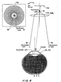
- an "IrisIdent” (registered trademark) system made of SENSAR Inc. in the U.S.A. is used as a practical system. As shown in FIG.16 , this system roughly comprises two illumination parts 110, a camera part 111, a processing part 112, and cables 113 for connecting the camera part 111 to the processing part 112. And then, the processing part 112 is connected to a host computer (not shown).
- a personal recognition processing using the system is generally performed according to the following procedure.
- a three-dimensional position of the eye of human locating at the front of the camera part 111 is calculated on the basis of stereoscopic vision by two wide-angle cameras in the camera part 111. This calculation is performed by the processing part 112 on the basis of image pickup information fed from the wide-angle cameras.
- a zoom camera in the camera part 111 is focused on the three-dimensional position fed from the processing part 112 and zoom magnification is inversely proportioned to the distance.
- an iris image caught by the zoom camera is taken with a CCD image sensor of said zoom camera and is fed to the processing part 112.
- the processing part 112 divides an iris portion (a region from the inner boundary to the outer boundary of the iris) in the taken iris image into eight concentric bands so as not to be influenced by variations in the pupil diameter. This is because the inside of the iris portion stretches and contracts in response to change in the pupil and thus the iris pattern itself stretches and shrinks. But, the outside of the iris portion does not change. '
- a convolution operation using a two-dimensional Gabor filter for feature extraction is performed every the divided band and a band-pass filtering is performed and the result is formed in binary code.
- an iris code of 256 bits is calculated from the obtained binary information every the band.
- the processing part 112 performs personal identification by deciding whether the calculated iris code is matched with the previously registered iris code or not. This personal identification may be performed through the host computer (not shown) connected to the processing part 112.
- the normal CCD image sensor arranged in a grid shape is used when the iris image is acquired, so that a coordinate of the iris portion of the iris image taken by the CCD image sensor must be transformed from an orthogonal coordinate system to a polar coordinate system and further, the convolution operation to each the transformed band must be performed. Since it takes an enormous time to process the coordinate transformation or the convolution operation, the personal identification system had a problem that such the coordinate transformation or the convolution operation greatly affects a delay in processing time of the whole identification processing.
- an iris information sensor for obtaining an iris image signal of an iris of an eye characterized in that the iris information sensor comprises:
- an iris information acquisition apparatus for obtaining image information of an iris region, comprising:
- the read scan means for scanning the determined iris region may scan the determined iris region at least in the tangential direction.
- the read scan means for scanning the determined iris region may scan the determined iris region in the tangential and radial directions every given width.
- the read scan means may divide the determined iris region into predetermined concentric ring bands and determine the number of pixels of the radial direction of each ring band, and also read the output value corresponding to information of each ring band in which weighted mean is performed according to the number of pixels.
- the region determination means may determine the iris region according to amplitude of a feature extraction signal, said feature extraction signal obtained by passing the image signal through a band-pass filter, said image signal obtained by scanning the image pickup sensor in the tangential direction.
- the said region determination means may determine the iris region according to level variation in the image signal obtained by the scan in the radial direction of the image pickup sensor.
- the optical axis operation control means may calculate the direction and size of an error between the center of the iris image formed on the image pickup sensor and the pole of the polar coordinates of the sensor to control a matching of the center of the iris image with the pole of the polar coordinates of the sensor, by further passing the feature extraction signal through a low-pass filter, said feature extraction signal obtained by passing the image signal through the band-pass filter, said image signal obtained by scanning the image pickup sensor in the tangential direction.
- the iris information acquisition apparatus may further comprise illumination means for irradiating illumination light to the eye and a group of light receiving elements for receiving reflected light from the eye of the illumination light, the optical axis operation control means controlling a matching of the center of the iris image with the pole of the polar coordinates of the image pickup sensor according to an amount of receiving light of the group of light receiving elements.
- an iris information acquisition apparatus for obtaining image information of an iris region of an eye, comprising:
- the image pickup optical system means may include a zoom lens and definitely keeps the outer diameter of the iris image formed on the image pickup sensor by the zoom lens.
- the pixel of the image pickup sensor each may have a light receiving region with an approximately rhombic shape having each diagonal in the radial and tangential directions of the polar coordinates.
- the pixel of the image pickup sensor each may also be arranged in a region with an approximately rhombic shape surrounded by the light receiving regions with the approximately rhombic shape.
- the iris information acquisition apparatus may further comprise iris code generation means for generating an iris code according to the output value read by the read scan means.
- the iris code generation means may comprise comparison means for comparing a band-pass filter receiving the output value and output of the band-pass filter with a predetermined threshold value.
- the iris code generation means may generate the iris code by comparing the output value of a plurality of continuous pixels with output of a target pixel.
- the iris information acquisition apparatus may further comprises a group of light receiving elements for receiving reflected light from the eye of light irradiated by said illumination means, said optical axis operation control means controlling a matching of the center of the iris image with the pole of the polar coordinates of the image pickup sensor according to an amount of receiving light of the group of light receiving elements.
- the optical axis operation control means may calculate the direction and size of an error between the center of the iris image formed on the image pickup sensor and the pole of the polar coordinates of the sensor to control a matching of the center of the iris image with the pole of the polar coordinates of the sensor, by further passing the feature extraction signal through a low-pass filter, said feature extraction signal obtained by passing the image signal through the band-pass filter, said image signal obtained by scanning the image pickup sensor in the tangential direction.
- the optical axis operation control means may control a matching of the center of the iris image formed on the image pickup sensor by moving a mirror placed in an optical path between the eye of the iris of a subject and the sensor with the pole of the polar coordinates of the sensor.
- the optical axis operation control means may control a matching of the center of the iris image formed on the image pickup sensor by moving the sensor with the pole of the polar coordinates of the sensor.
- the optical axis operation control means may control a matching of the center of the iris image formed on the image pickup sensor by a vertical angle variable prism placed in an optical path between the eye of the iris of a subject and the sensor with the pole of the polar coordinates of the sensor.
- the optical axis operation control means may control a matching of the center of the iris image formed on the image pickup sensor by mutually translating a plurality of lenses placed in an optical path between the eye of the iris of a subject and the sensor with the pole of the polar coordinates of the sensor.
- the image pickup sensor may comprise a linear sensor in which pixels are arranged in the radial direction and rotation driving means for synchronously rotating the linear sensor around the pole of the polar coordinates, and a function equivalent to the group of the pixels of the polar coordinates may be achieved by the rotation of the linear sensor through the rotation driving means.
- the pixel constructing the image pickup sensor each may be made of a MOS sensor or a CCD sensor.
- the pixel constructing the image pickup sensor each may be made of a device for detecting edge information electrically or optically.
- the pixel density in the radial direction of each pixel of the image pickup sensor may correspond to the rate of stretching and shrinking of the iris.
- the image pickup sensor may be made of a group of pixels arranged in a spiral shape extending in the radial direction.
- an iris identification apparatus for acquiring an iris code representing information of an iris region of an eye and comparing and matching the acquired iris code with a previously registered iris code, comprising:
- the matching means may match the iris region including a region hidden by the eyelids.
- the iris identification apparatus may further comprise a nonvolatile memory for storing the previously registered iris code, and means for encoding or ciphering the matched result in order to secure security.
- the iris identification apparatus may further comprise means for adjusting identification determination level used when matching the generated iris code with the previously registered iris code.
- an iris identification apparatus for acquiring information of an iris region of an eye and comparing and matching the acquired information of the iris region with information of an iris region registered previously, comprising:
- the image pickup optical system means may include a zoom lens and definitely keeps the outer diameter of the iris image formed on the image pickup sensor by the zoom lens.
- the matching means may match the iris region including a region hidden by the eyelids.
- the iris identification apparatus may further comprise a nonvolatile memory for storing the previously registered iris code, and means for encoding or ciphering the matched result in order to secure security.
- the iris identification apparatus may further comprise means for adjusting identification determination level used when said matching means performs said matching.
- an iris information sensing method for obtaining an iris image signal of an iris of an eye characterized in that the iris information sensing method comprises:
- the previously registered iris code may be stored in a nonvolatile memory, and the iris identification method may further comprise the steps of encoding or ciphering the matched result in order to secure security.
- an iris identification method for acquiring an iris code representing information of an iris region of the eye and comparing and matching the acquired iris code with a previously registered iris code, comprising the steps of:
- the image pickup optical system means may include a zoom lens and may definitely keep the outer diameter of the iris image formed on the image pickup sensor by the zoom lens.
- FIG.1 shows the whole construction of an iris recognition system, namely, an iris information acquisition apparatus according to a first embodiment of the present invention.
- this iris recognition system includes two wide-angle cameras 1a, 1b and a zoom camera 7.
- the wide-angle cameras 1a and 1b take an image of a human eye of a subject of recognition by CCD's 2a and 2b, respectively, and image signals obtained by the CCD's 2a and 2b are fed to an iris acquisition controller 6 after reducing noise of the taken signal with CDS circuits 3a and 3b.
- CCD drivers 5a and 5b for driving the CCDs 2a and 2b as well as a processing operation of the CDS circuits 3a and 3b are controlled on the basis of a synchronous control signal generated by control parts 4a and 4b.
- the system shown in FIG.1 includes the iris acquisition controller 6 which specifies a three-dimensional position of the human eye of the subject of recognition according to an image signal inputted from the cameras 1a and 1b, and outputs signal or data indicating the specified result to the zoom camera 7.
- the zoom camera 7 drives and controls a steering motor 7b to move a mirror 8c so that the image pickup direction of the zoom camera 7 is directed to the human eye according to the three-dimensional position obtained as mentioned above. Also, the zoom camera 7 controls a zoom/focus motor 7a for driving a zoom lens optical system 8 to be focused on the three-dimensional position of the human eye and regulates an amount of zoom so that an iris image of the pickup subject coincides with an image pickup region of a sensor 10. An iris sensor part 9 in the zoom camera 7 feeds position error and focus error information between the iris image taken by the sensor 10 and the sensor to the iris acquisition controller 6.
- the iris acquisition controller 6 servocontrols each part of the camera system described above until information of the iris part described above is obtained.
- this information namely an iris code is matched with a previously registered iris code held within the iris acquisition controller 6 or held by a host computer (not shown).
- the matching may be performed either by the iris acquisition controller 6 or by the host computer.
- the host computer may control each part of the camera system, or the sensor part itself may control each part by each error signal of the iris sensor part 9.
- the information of the iris part which the iris acquisition controller 6 receives from the iris sensor part 9 is an iris code formed in a binary form by the sensor part 9. A construction of this iris sensor part 9 will be described in detail with reference to FIGS.2 and 3 .
- FIG.2 shows a detailed construction of the iris sensor part 9 having the sensor 10.
- This sensor 10 has a pixel array pattern of polar coordinate type shown in FIG.3 , and each pixel has, for example, a shape partitioned by straight lines extending in the radial direction (r direction) and circumferential circles and light receiving areas of each pixel become larger as the pixel locates at the more outside of the radial direction.
- the sensor 10 may comprise CCD image sensors or MOS type image sensors.
- the shape of this pixel array pattern is suited for each ring shape in the case of acquiring the iris code.
- the outer circumferential circle L1 of the pixel array pattern has the size so as to match with the outer circumference of the iris to be taken or become slightly larger than the outer circumference of the iris, when focusing and zooming control are performed, so that necessary resolution may be obtained when the iris image is taken.
- the inner circumferential circle L2 has the size smaller than the size when the pupil becomes minimum, when the outer circumference of the iris matches with the circle L1. Since the pupil region always exists, the pixel array pattern has a region of a center part E1 surrounded by the circle L2. In this case, it is necessary to control alignment with the center of the iris and that of the pixel array pattern, since the iris image is taken by the sensor 10 having the pixel array pattern of polar coordinate type shown in FIG.3 .
- a circuit 11 for detecting the inner diameter of the iris detects the boundary between the iris and the pupil of the radial direction in the taken iris image through the level variation, that is, an edge detection is performed, with the result that the inner diameter of the iris is calculated.
- a circuit 12 for detecting the outer diameter of the iris detects the outer circumference of the iris in the taken iris image through the level variation, that is, the edge detection is performed, with the result that the outer diameter is calculated.
- the detecting circuits 11 and 12 output a steering error signal, namely a signal for indicating a position error of image formation to the iris acquisition controller 6 according to positions of the inner and outer diameters of the iris.
- the outer diameter detecting circuit 12 outputs a zoom error signal to the iris acquisition controller 6.
- the inner diameter detecting circuit 11 calculates the difference between the outer diameter of the sensor 10 and the detected inner diameter to calculate the number of pixels of the radial direction of the sensor 10 corresponding to said difference, and the value obtained by dividing this number of pixels by the number of ring bands (for example, 8) is fed to a weighted mean processing part 13 as the number i of pixels of the radial direction assigned to one ring.
- the number i of pixels is set to "3" in FIG.3 .
- the outer diameter of the iris image may not always be matched with the outer diameter of the sensor 10.
- a zoom optical system is unnecessary and the number i of pixels is calculated on the basis of the difference between the outer diameter detected by the outer diameter detecting circuit 12 and the inner diameter detected by the inner diameter detecting circuit 11, but the outer diameter of the sensor 10 must be larger than the outer diameter of the iris image.
- the weighted mean processing part 13 calculates a weighted mean of pixel output signals of the number i of pixels when receiving the pixel output signals from the number i of pixels.
- the reason why this weighted mean is calculated is because the size of the pixel becomes larger as the pixel of the sensor 10 locates at the more outside as shown in FIG.3 , so that compensation of sensitivity variation caused by the increase in the light receiving area must be performed, and influence caused by a slight error of the dividing position of each ring and a steering error due to variation in the pupil diameter is decreased by performing the weighting to the center of each ring.
- the value calculated by the weighted mean processing part 13 is fed to a high-pass filter 14 as an image output signal.
- the level or magnitude of high pass component of the image output signal from the high-pass filter 14 is taken out and is outputted as a focus control signal.
- steering error signal, zoom error signal and focus control signal are respectively fed to the iris acquisition controller 6.
- the controller 6 controls the steering motor 7b and the zoom/focus motor 7a in the zoom camera 7 so that the iris of the image pickup subject is matched with the center of the sensor 10 as well as the outer diameter of the iris is matched with the outer circumference of the sensor 10, and the focusing is performed.
- a timing generator 20 drives a driver 21 of the sensor 10 and performs a scanning for outputting the pixel signals in the ⁇ direction (rotational direction) every ring.
- the signal outputted from each pixel is calculated or operated by the weighted mean processing part 13 to perform the weighted mean as described above and is fed to a band-pass filter 15.
- the band-pass filter extracts the change point in the fed pixel output signal, namely the signal change in the ⁇ direction of the iris pattern.
- a binary circuit 16 generates an iris code formed in a binary format, by performing conversion of the extracted signal into binary signal by a built-in comparator. Then, this iris code is fed to the iris acquisition controller 6 through a latch circuit 17.
- the controller 6 compares the iris code of each ring band with the iris code previously registered in the host computer and so on so that a personal identification is performed.
- the iris code may preferably be ciphered or encoded in order to secure security to transmit between each circuit device.
- a circuit 18 for detecting effective range of the outer diameter of the iris detects the boundary between the eyelids and the iris through the level variation in the radial direction to calculate the upper and lower limits of the iris to be taken.
- a regulating part 19 controls, for example, the timing generator 20 so as to invalidate the range beyond these upper and lower limits. For example, in the case of a MOS sensor, addressing in the range beyond the limits may be skipped.
- the hide may be ignored.
- some degree of correlation decreases due to the matching of comparison between the eyelids when identifying the iris, but it does not matter.
- the effective iris codes or the effective code portions in the iris code are compared each other when comparing the iris codes and thus, influence of the eyelids may be removed. That is, only the effective portions out of the registered iris codes are used as a comparison subject.
- the eye is preferably opened wide so that the iris is not hidden by the eyelids as wide as possible.
- error-detecting codes such as checksum or CRC code
- a footer of the iris code reliability on the registered iris codes may be improved.
- the above header and footer may be added to the iris codes registered or the iris codes obtained from the sensor 10, or both the iris codes.
- the comparison may be performed as an exclusive OR (EXOR) operation simply, unless a tilt of the eye exists, but the tilt exists generally so that the registered iris code is correlated with the detected iris code and it is determined whether a person having the detected iris code is the registered person or not, on the basis of the value with the highest correlation.
- So-called "hill-climbing" method etc. is used as a method for varying and obtaining a start point of comparison, and the correlation values shifted by one point back and forth are compared each other and the climbing is performed in the direction of higher correlation.
- the iris codes may be compared immediately without a correlation processing in the case of comparison if the tilt of the ⁇ direction of the eye to be taken can be detected.
- output of the band-pass filter 15 may be used, as another embodiment of the circuits 11 and 12 for detecting the inner and outer diameters of the iris, so that the inner and outer diameters of the iris may be detected readily. Also, by adding the low-pass filter 22 and using output of this filter 22, the steering error signal may be outputted readily. By performing feedback of this steering error signal directly to the steering motor 7b, steering of the zoom camera 7 may be servocontrolled directly.
- the driver 21 scans the pixel signal of the sensor 10 from the inner circumference of the sensor 10 to the outside in the radial direction, first, the output signal level from the band-pass filter 15 is almost zero regardless of an angle ⁇ of the rotation direction as shown in FIG.4A .
- the output signal level indicating detection of the iris portion appears as shown in FIG.4B , and this output signal is a signal depending on an iris pattern of the iris portion. Further, when the pixel signal is scanned in the radial direction, the output signal level is saturated to a certain level and gradually approaches inclination determined by the ratio of light receiving area of each pixel as shown in FIG.4C .
- the circuit 11 for detecting the inner diameter of the iris detects the position on the sensor 10 as the inner diameter of the iris, when the output signal level from the band-pass filter 15 has become a certain level, for example, the output signal level has appeared or has reached saturation.
- the circuit 12 for detecting the outer diameter of the iris may detect the outer diameter of the iris through the fact that the output signal level from the band-pass filter 15 has become a predetermined level lower from the certain level or has become a level equal to or lower than a predetermied level. But, in the case of scanning to the outside in the radial direction, the scanning position, for example, immediately before the output signal level has become the certain level or lower is detected as the outer diameter of the iris.
- the scanning may be performed from the outer circumference of the sensor 10 to the inside in the radial direction. Also, it is possible to calculate the inner diameter of the iris by the scanning to the outside in the radial direction, and to calculate the outer diameter by the scanning to the inside in the radial direction, so that the inner and outer diameters may be obtained at higher speed in this manner.
- the output signal from the band-pass filter 15 thus, the inner and outer diameters of the iris may be detected readily without a complex image processing.
- an envelope L10 of the output signal level for the angle ⁇ of the rotational direction may vary with respect to the angle ⁇ of the rotational direction, and level variation in this envelope L10 means that the zoom camera 7 is not directed to the eye of the image subject.
- the signal of an envelope level of the scanned image signal may be outputted and the level difference of this signal may be used as the steering error signal.
- the steering error signal may be outputted by a simple processing without using a complex image processing.
- the steering may be servocontrolled directly using this steering error signal.
- the band-pass filter 15 and the low-pass filter 22 receive the signal through the weighted mean processing part 13 and perform a filtering, but a direct pixel signal from the sensor 10 is preferably used, after filtering, as the signal fed to the inner and outer detecting circuits 11 and 12.
- the sensor 10 is constructed in pixel arrangement having the pixel array pattern of polar coordinate type shown in FIG.3 , a processing for transforming the orthogonal coordinate system into the polar coordinate system in the case of acquiring the image signal by the sensor having the pixel arrangement of orthogonal coordinate type is eliminated so that a processing speed for acquiring the iris code may be improved remarkably.
- the length of pixel in the radial direction may be varied according to the rate of stretching and shrinking of the iris. That is, the rate of stretching and shrinking of the iris depends on a thickness of the iris, and normally the thickness of the iris is thinner toward the center of iris and the iris is easy to stretch and shrink, so that the length of pixel of the radial direction in the pixel close to the center may be lengthened according to this nature of the iris. By varying the length of pixel of the radial direction thus, rate of recognition may be improved.
- FIG.5 shows a construction of an iris sensor part 9a of an iris recognition system according to the second embodiment.
- the iris sensor part 9a is different from the iris sensor part 9 shown in FIG.2 in that a sensor 10a is used instead of the sensor 10 and a construction of the weighted mean processing part 13 is eliminated.
- the other constructions are the same as those of the first embodiment and have the same reference characters as those of the first embodiment.
- the sensor 10a has pixel arrangement of a pixel array pattern of polar coordinate type like the sensor 10 and has an illuminating LED 31 (light emitting diode) which is placed on an optical axis of the sensor and illuminates the eye of human with visible light. Also, it is favorably constructed so that the LED 31 may illuminate the eye of human exactly by shifting the position of a light emitting plane of the LED 31 optically from a light receiving plane of the sensor 10a. Also, an EL (electroluminescence) device etc. other than the LED 31 may be used as illumination means.
- the circuit 11 for detecting the inner diameter of the iris detects the inner diameter of the iris, and the difference between this detected inner diameter and the inner circumference of the sensor 10a, namely a pupil diameter error signal is generated and is fed to the iris acquisition controller 6.
- the iris acquisition controller 6 controls brightness of the LED 31 so as to eliminate the pupil diameter error signal. That is, this control is to increase the brightness of the LED 31 when the pupil diameter is longer than the inner circumference of the sensor 10a and to decrease the brightness of the LED 31 when the pupil diameter is shorter than the inner circumference of the sensor 10a.
- the pupil diameter always matches with the inner circumference of the sensor 10a and the outer circumference of the sensor 10a matches with the outer diameter of the iris through the steering error signal, the zoom error signal, etc. so that an iris portion of an image subject is taken with the iris portion always matching with the pixel array pattern on the sensor 10a.
- the width in the radial direction of each pixel in the sensor may be determined based on necessary resolving power, so that for example, the length of the sensor in the radial direction may be divided into eight portions equally, and an iris code may be generated directly using an image pickup signal from the sensor 10a.
- a recognition processing may be performed with a very simple pattern matching by previously registering an iris image. That is, since the inner and outer diameters of the iris are known, the pattern matching may be performed only by rotation at the center of the iris so that a comparison speed may be improved considerably.
- means for detecting a position error is constructed by providing an array of photodiodes 32 in the center of the sensor 10a so that steering of the zoom camera 7 may be controlled. That is, light emitted by the LED 31 is reflected on the surface of the eye and is received by the photodiodes 32.
- the steering control is performed by using the difference between the amounts of light reception in the array position of each photodiode 32 as a steering error signal to feed the difference to the iris acquisition controller 6.
- the difference between the amounts of light reception may be employed instead of generating the steering error signal in the inner detecting circuit 11.
- output of the array of the photodiodes 32 is fed back to the steering motor 7b directly and analogue servocontrol may be performed so that miniaturization and weight-saving of the system may be improved.
- FIG.6 shows an example of a position relationship of the eye to the sensor 10a etc. in the apparatus of FIG.5 .
- illuminating light 33 emitted from the illuminating LED 31 is irradiated to the eye through an image pickup lens 8b.
- the pupil diameter of the eye is controlled according to the intensity of this irradiated light.
- the image of the iris having the controlled pupil diameter is formed on the sensor 10a through the image pickup lens 8b.
- reflected light 34 indicates the situation that the reflected light from the LED 31 is irradiated on the photodiodes.
- the photodiodes 32 described above are preferably arranged in the proximity of the optical axis of the center of the sensor 10a and may also be provided outside the outer circumference of the pixel array pattern.
- the LED 31 may be arranged in the outside of the optical axis pairing with the photodiodes 32, for example.
- a light emitting device for emitting invisible light such as infrared rays (IR) and the photodiodes 32 for receiving reflected light from this light emitting device may be provided in the same position as the LED 31 and so on of the second embodiment.
- the means for detecting a position error is constructed by a combination of such a light emitting device and the photodiodes 32, and the steering error signal is obtained so that positioning of the iris image and the sensor 10 may be performed.
- the pixel array pattern of the sensor 10a constructing the second embodiment was the pixel array pattern of polar coordinate type like the sensor 10 and was a set of pixels each having a kind of approximately rectangular shape with the pattern divided by the straight lines of the radial direction every predetermined angle and the concentric circles every predetermined radius.
- a sensor 10b has the pixel array pattern which is polar coordinate type and is a set of pixels of an approximately rhombic shape having each diagonal in the circumferential direction and the radial direction as shown in FIG.7 .
- the rhombic pixels are disposed also in this space so as to effectively utilize the space.
- the rhombic pixels on a concentric circle deviates from the rhombic pixels on other concentric circle adjacent this in the ⁇ direction by half pixel mutually, and resolution may be improved.
- the shape of the pixel is not limited to the rhombic shape.
- each pixel may automatically perform weighting in sensitivity within each ring band in the radial direction, from the shape itself of the light receiving part and output the weighted value.
- the degree of the weighting does not increase the false rejection rate so that the false rejection rate will be suppressed even if there is some steering error, namely the center of the sensor 10b deviates from the center of the iris image in some degree.
- FIG.8 shows an example of a sensor in which each pixel has an elliptic shape.
- FIG.9 shows a construction of a sensor in which each pixel has a quadrangular or square shape and has the same size.
- the size of each pixel is constant regardless of a position of the radial direction of the sensor so that the difference in sensitivity of each ring band is eliminated.
- FIG.10 shows a construction of an iris sensor part 9b of an iris recognition system according to the third embodiment.
- the iris sensor part 9b is different from the iris sensor part 9a shown in FIG.5 in that a sensor 10c which is rotated and driven is used instead of the sensor 10a.
- the other constructions are the same as those of the second embodiment and have the same reference characters.
- the sensor 10c is not an area sensor such as the sensors 10, 10a and 10b but a line sensor or a linear sensor.
- the sensor 10c synchronously rotates about the axis corresponding to the center of the sensors 10, 10a and 10b by a sensor driving motor 40, and a detection equivalent to that of the area sensor such as the sensors 10, 10a and 10b is performed by one rotation.
- This synchronous rotation is to rotate in synchronization with a timing pulse fed from a timing generator 20 and so on.
- the sensor 10c is rotating so that the pixel signal is outputted using a rotary transformer or a sliding brush and so on.
- the pixels of the sensor 10c are formed in the rhombic shape having the diagonal in the radial direction like FIG.7 .
- the reason why this rhombic shape is adopted is because an operation processing of the weighting is eliminated as described above.
- the length of the radial direction of the rhombic pixel as described above may be varied according to the rate of stretching and shrinking of the iris.
- the senor 10c may be constructed simply and readily in comparison with the sensors 10, 10a and 10b.
- each pixel of the linear sensor may not have the rhombic shape and, for example, may have the rectangular shape or the other shapes.
- the fourth embodiment is intended to output the edge image directly by the sensor and the iris code is obtained by converting this outputted signal into the binary format by the binary circuit 16.
- the band-pass filter 15 in the first embodiment to the third embodiment is eliminated, and the construction of the circuits 11 and 12 for detecting the inner and outer diameters of the iris, the high-pass filter 14, and the circuit 18 for detecting the effective range of the outer diameter of the iris which perform a processing on the basis of the edge image is also simplified so that a processing load may be reduced.
- This construction of the sensor for directly outputting the edge image is achieved by an optical edge processing using an artificial retina lens disclosed in, for example, Japanese Patent Laid-Open Publication No.5-297325 . That is, it is constructed so as to receive light inputted to each pixel in the first embodiment to the third embodiment through a spatial frequency filter and such a construction is an idea of "eye for eye" as it were.
- this feature extraction may be electrically performed.
- an outline detecting circuit which is adopted in a neurochip devised by C. A. Mead et al. in California Institute of Technology (see C. A. Mead and M. A. Mahowald, "A Silicon Model of Early Visual Processing", Neural Networks, vol.1, pp.91-97 of 1988 ) and imitates primary sight of the human may be used for this purpose.
- FIG.11 shows a construction example of an iris sensor part using such a sensor.
- the construction shown in FIG.11 has no construction for converting an image and extracting an edge image, and in the construction, an image edge signal obtained from the sensor is formed in a binary format directly by the binary circuit 16 and an iris code is inputted to a latch 17. Thus, no band-pass filter 15 shown in the.construction of FIG. 5 is required.
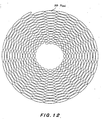
- the senor has the pixel array pattern of polar coordinate type in each embodiment described above, the sensor is not limited to this pattern and, for example, as shown in FIG.12 , the sensor may have a pattern in which pixels PP are arranged in a spiral shape from the inner diameter of the iris of the sensor.
- a processing may be performed so as not to be affected by the variation in the pupil diameter, for example, by assigning serial numbers to each pixel from the outer circumference and detecting that the pixels from No.1 to No.N are the iris portion and normalizing said pixels with N.
- serial numbers to each pixel from the outer circumference and detecting that the pixels from No.1 to No.N are the iris portion and normalizing said pixels with N.
- read control of each pixel is simplified.
- an one-dimensional read scan may be implemented by joining the pixels of each concentric circle in the same manner of the spiral sensor.
- the iris image as a color sensor in which the pixels are arranged in the spiral shape with three R, G, B, addressing of each pixel forming the iris portion is facilitated.
- a comparison circuit for comparing the detected iris code with a predetermined code into a sensor chip itself and incorporating a nonvolatile memory capable of registering the iris codes for comparison to some degree simultaneously, it may be constructed so as to output not the iris code but the comparison result, namely the identification result (for example, OK or NG) from the sensor part.
- this output is preferably ciphered or encoded to feed in order to secure security.
- the construction may be simplified using relative parallel translation of a VAP (vertical angle variable prism) or a plurality of lenses instead of preprocessing such as alignment of the iris by the wide-angle cameras mentioned above.
- VAP vertical angle variable prism
- the iris image may be obtained by control of only an optical system including the vertical angle variable prism 8a and a zoom lens 8b and a zoom camera including an iris sensor part 9c.
- the numeral 7c designates a pan/tilt motor for driving the prism 8a and the numeral 7d designates a zoom/focus motor.
- the numeral 6a designates an iris acquisition controller and a control part of the wide-angle cameras as the iris acquisition controller 6 shown in FIG.1 is not required so that the controller 6a is simplified.
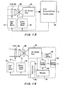
- FIG.14 shows a construction in which a controller 50 for driving and controlling the VAP 8a and the zoom lens 8b, a memory 51 for storing the iris code for comparison, a comparison circuit 52 for comparing the detected iris code with the iris code stored in the memory, and a cipher circuit 53 are integrated into one chip.
- a controller 50 for driving and controlling the VAP 8a and the zoom lens 8b a memory 51 for storing the iris code for comparison
- a comparison circuit 52 for comparing the detected iris code with the iris code stored in the memory
- a cipher circuit 53 are integrated into one chip.
- identification determining level that is, threshold of correlation degree of iris codes
- a determination value register 54 is provided.
- a determination value indicating an identification determining level can be stored in the determination value register 54, for example, from external, to designate a required correlation level. Also, it is possible to selectively supply one of a plurality of determination values from external to the determination value register 54.
- the identification determination level adjustable internally, for example, based on the determination value supplied from a microprocessor in the iris recognition system.
- the microprocessor may generate the determination value, for example, depending on various conditions, such as brightness of the location the iris recognition system is installed, required precision of recognition, and the like.
- facing type it may be constructed so that a three-dimensional alignment processing, which has been performed by the wide-angle cameras 1a and 1b, to the zoom lens 8b is performed by approach of the subject to a predetermined distance and position from the apparatus, and only fine adjustment to perform positioning and focusing so as to direct the optical axis of the zoom lens 8b precisely toward the position of the eye using the known VAP 8a is controlled by the iris acquisition controller or the sensor part itself.
- the margin of range of such a predetermined position is about ⁇ 3 cm in a distance of 25 to 30 cm from the apparatus, so-called, a distance of distinct vision.
- the pupil diameter may be adjusted simultaneously if the subject is asked to look this LED.
- a method in which a person peeps into the zoom lens 8b from a given window etc. may be adopted without a method for facing at the distance of distinct vision.
- the difference between the facing method and the peeping method is that a focal length of the image pickup lens 8b only differs.
- the lens 8b may not always be a zoom lens and may be a lens with single focal point or a lens capable of switching the focal length.
- focusing may be performed even using a camera with a fixed focal point etc. by displaying an iris image and a cross line on the screen to perform steering, and displaying a message of "please approach the screen a little", for example.
- the iris image is obtained by attaching an adapter lens to a normal camera mounted in the personal computer as an attachment or an option other than a method for attaching a dedicated camera to the iris recognition system, and coordinate transformation is performed by a software of the personal computer and the iris code may be obtained.
- the iris code may be obtained by connecting a dedicated sensor and a normal CCD/MOS sensor to the iris recognition system through a half mirror and mounting both the sensors.
- a function equivalent to the construction including the band-pass filter and the comparator may be achieved by calculating the average of outputs of continuous N pixels and comparing this average with output of a target pixel.
- a comparison processing may be executed without being affected by a scan speed, and also, a bandwidth of the band-pass filter may be varied by selecting the value of N, so that more flexible processing may be performed.
- the continuous N pixels may be selected from the range including the pixels to be compared or from backward and forward of the range including the pixels to be compared.
- the method has been mainly described in which features of the tangential direction of the iris are extracted by scanning in the tangential direction of the sensor.
- resolving power is reduced by taking a weighted mean of the tangential direction according to this (for example, 32 division) and the scanning in the radial direction is performed, so that redundancy may be reduced favorably.
- a circuit construction like the circuit construction used for scanning in the tangential direction may be used to perform the scanning in the radial direction.
- a circuit construction like the circuit construction used for scanning in the tangential direction may be used to perform the scanning in the radial direction.
- the band-pass filter by the comparison with the average of the N pixels it may also be used as the band-pass filter in the radial direction.
- the present invention may be applied to the eye of human as well as animals generally and, for example, individual identification thereof may be performed.
- the present invention uses an image pickup sensor comprising a group of pixels arranged in polar coordinates, it is unnecessary to transform an orthogonal coordinate system into a polar coordinate system in order to obtain an iris code, and the iris code may be generated at high speed without a dedicated processor, so that time necessary for personal identification may be saved and a load of a processing apparatus may be reduced.
- an image of an iris portion with the same size always may be acquired by using means for regulating light, an information processing of the iris portion is facilitated and particularly, a check processing using a pattern matching may also be performed.
- a load necessary for generation processing of the iris code is reduced and the processing may be performed at high speed and further, miniaturization and weight-saving of the system may be promoted.
- the pixels of the image pickup sensor in approximately rhombic shape, it is unnecessary to perform compensation of sensitivity and weighting, with the result that the load necessary for generation processing of the iris code may be reduced and the time may be saved.
Description
- This invention relates generally to an iris information acquisition apparatus, an iris identification apparatus and the others, and particularly to techniques capable of remarkably reducing time from an image pickup of an iris image to generation of an iris code, and capable of simplifying the iris information acquisition apparatus, the iris identification apparatus and the like.
- Security systems accompanying development of high computerization in recent years require high reliability and convenience. In these security systems, for example, key, password, ID card, IC card, signature, voiceprints, fingerprints, biometric features (face pattern, set of teeth, retina, iris pattern and so on) are used as recognition means. Generally, in order of description of the above recognition means, degree of problems that these recognition means must be carried, are forgotten, are difficult to operate, are lost, are forged, etc. decreases, with the result that the recognition means have high reliability while the security systems become complicated and expensive.
- The fingerprints among the above recognition means have been adopted by the police etc. of the whole world in the past and have been the most familiar personal identification means. However, a pattern of the fingerprints at the time of registration is not identical with that of the fingerprints at the time of matching since the fingertips are soft, and also, a false acceptance rate which is a probability of deciding the patterns identical in spite of the different patterns of the fingerprints and a false rejection rate which is a probability of deciding the patterns different in spite of the identical patterns of the fingerprints are said to become about 10 to 20 % since the fingerprints themselves are easy to transform.
- Also, in a system for matching a blood vessel pattern on the retina, to detect this blood vessel pattern, behavior of looking through a device for detecting the blood vessel pattern is forced and the false rejection rate becomes high due to influence of retinitis (hemorrhage of fundus oculi, white patch, exudation) and so on.
- On the contrary, the iris pattern which has a demerit of hiding the iris in an eyelid is said to be almost immutable until death since two years of age, and a personal identification rate using the iris pattern has high reliability and thus, the iris pattern is said to be the most excellent personal identification system. As shown in
FIG.15 , the iris means aregion 101 having a pattern drawn radially on the outside of apupil 100. - The personal identification system using such the iris pattern is disclosed in
U.S.Patent No.5,291,560 , for example. Also, an "IrisIdent" (registered trademark) system made of SENSAR Inc. in the U.S.A. is used as a practical system. As shown inFIG.16 , this system roughly comprises twoillumination parts 110, acamera part 111, aprocessing part 112, andcables 113 for connecting thecamera part 111 to theprocessing part 112. And then, theprocessing part 112 is connected to a host computer (not shown). A personal recognition processing using the system is generally performed according to the following procedure. - First, a three-dimensional position of the eye of human locating at the front of the
camera part 111 is calculated on the basis of stereoscopic vision by two wide-angle cameras in thecamera part 111. This calculation is performed by theprocessing part 112 on the basis of image pickup information fed from the wide-angle cameras. - Secondly, a zoom camera in the
camera part 111 is focused on the three-dimensional position fed from theprocessing part 112 and zoom magnification is inversely proportioned to the distance. - Thirdly, by this, an iris image caught by the zoom camera is taken with a CCD image sensor of said zoom camera and is fed to the
processing part 112. - Fourthly, the
processing part 112 divides an iris portion (a region from the inner boundary to the outer boundary of the iris) in the taken iris image into eight concentric bands so as not to be influenced by variations in the pupil diameter. This is because the inside of the iris portion stretches and contracts in response to change in the pupil and thus the iris pattern itself stretches and shrinks. But, the outside of the iris portion does not change. ' - Fifthly, a convolution operation using a two-dimensional Gabor filter for feature extraction is performed every the divided band and a band-pass filtering is performed and the result is formed in binary code.
- Sixthly, an iris code of 256 bits is calculated from the obtained binary information every the band.
- Lastly, The
processing part 112 performs personal identification by deciding whether the calculated iris code is matched with the previously registered iris code or not. This personal identification may be performed through the host computer (not shown) connected to theprocessing part 112. - In the personal identification system using the iris pattern mentioned above, however, the normal CCD image sensor arranged in a grid shape is used when the iris image is acquired, so that a coordinate of the iris portion of the iris image taken by the CCD image sensor must be transformed from an orthogonal coordinate system to a polar coordinate system and further, the convolution operation to each the transformed band must be performed. Since it takes an enormous time to process the coordinate transformation or the convolution operation, the personal identification system had a problem that such the coordinate transformation or the convolution operation greatly affects a delay in processing time of the whole identification processing.
- Although the above problem may be solved by enhancing the calculation capability of the
processing part 112, a new problem has arisen in that the enhancement of the calculation capability requires a high cost naturally, and obstructs miniaturization and weight-saving of the personal identification system including theprocessing part 112. - Accordingly, it is an object of the present invention to provide an iris recognition and identification method and its system capable of removing the above-mentioned problems of the prior art.
- It is another object of the present invention to provide an iris recognition and identification method and its system capable of remarkably reducing time required from image pickup of an iris image to generation of an iris code as well as of simplifying the system.
- It is yet another object of the present invention to provide an iris recognition and identification method and its system capable of remarkably reducing time required from image pickup of an iris image to generation of an iris code and further capable of simplifying the system.
- According to an aspect of the present invention, there is provided an iris information sensor for obtaining an iris image signal of an iris of an eye characterized in that the iris information sensor comprises:
- an image pickup sensor having a group of photoelectric conversion pixels arranged in concentric circles or in a spiral shape around a pole of polar coordinates; and
- a position error detecting means that detects a position error between the center of an iris image formed on the image pickup sensor and the pole of the polar coordinates to provide a position error signal, wherein the position error signal is used to cause image light from an iris region of an eye to be projected on the image pickup sensor so that the center of the iris image formed on the sensor substantially matches with the pole of the polar coordinates of the sensor, to read out an iris image signal by sequentially scanning the photoelectric conversion pixels of the sensor.
- According to another aspect of the present invention, there is provided an iris information acquisition apparatus for obtaining image information of an iris region, comprising:
- an iris image sensor according to the first aspect of the invention;
- image pickup optical system means for focusing image light from the iris region of an eye onto the image pickup sensor;
- optical axis operation control means for matching the center of an iris image formed on the sensor with the pole of the polar coordinates of the sensor;
- region determination means for determining the iris region by acquiring the inner and outer diameters of the iris according to an iris image signal obtained by the sensor; and
- read scan means for scanning the determined iris region in a predetermined sequence and obtaining an output value corresponding to information of the iris region.
- The read scan means for scanning the determined iris region may scan the determined iris region at least in the tangential direction.
- The read scan means for scanning the determined iris region may scan the determined iris region in the tangential and radial directions every given width.
- The read scan means may divide the determined iris region into predetermined concentric ring bands and determine the number of pixels of the radial direction of each ring band, and also read the output value corresponding to information of each ring band in which weighted mean is performed according to the number of pixels.
- The region determination means may determine the iris region according to amplitude of a feature extraction signal, said feature extraction signal obtained by passing the image signal through a band-pass filter, said image signal obtained by scanning the image pickup sensor in the tangential direction.
- The said region determination means may determine the iris region according to level variation in the image signal obtained by the scan in the radial direction of the image pickup sensor.
- The optical axis operation control means may calculate the direction and size of an error between the center of the iris image formed on the image pickup sensor and the pole of the polar coordinates of the sensor to control a matching of the center of the iris image with the pole of the polar coordinates of the sensor, by further passing the feature extraction signal through a low-pass filter, said feature extraction signal obtained by passing the image signal through the band-pass filter, said image signal obtained by scanning the image pickup sensor in the tangential direction.
- The iris information acquisition apparatus may further comprise illumination means for irradiating illumination light to the eye and a group of light receiving elements for receiving reflected light from the eye of the illumination light, the optical axis operation control means controlling a matching of the center of the iris image with the pole of the polar coordinates of the image pickup sensor according to an amount of receiving light of the group of light receiving elements.
- According to still another aspect of the present invention, there is provided an iris information acquisition apparatus for obtaining image information of an iris region of an eye, comprising:
- an iris information sensor according to the first aspect of the present invention;
- image pickup optical system means for focusing image light from the iris region onto the image pickup sensor;
- illumination means for irradiating illumination light to the eye having the iris;
- optical axis operation control means for matching the center of an iris image formed on the sensor with the pole of the polar coordinates of the sensor;
- light adjustment control means for definitely controlling
- the inner diameter of the iris image formed on the sensor by irradiating visible light to the eye having the iris from the illumination means and adjusting an amount of the light and defining the pupil diameter; and
- read scan means for scanning the sensor in a predetermined sequence and reading image information of the iris region.
- The image pickup optical system means may include a zoom lens and definitely keeps the outer diameter of the iris image formed on the image pickup sensor by the zoom lens.
- The pixel of the image pickup sensor each may have a light receiving region with an approximately rhombic shape having each diagonal in the radial and tangential directions of the polar coordinates.
- The pixel of the image pickup sensor each may also be arranged in a region with an approximately rhombic shape surrounded by the light receiving regions with the approximately rhombic shape.
- The iris information acquisition apparatus may further comprise iris code generation means for generating an iris code according to the output value read by the read scan means.
- The iris code generation means may comprise comparison means for comparing a band-pass filter receiving the output value and output of the band-pass filter with a predetermined threshold value.
- The iris code generation means may generate the iris code by comparing the output value of a plurality of continuous pixels with output of a target pixel.
- It is possible to add information on the effective range of the iris region to the iris code.
- It is also possible to add information on resolution of the image pickup sensor to the iris code.
- It is further possoible to add information on tilt of the eye to the iris code.
- It is further possible to add information on whether the iris code is the right eye or the left eye to the iris code.
- The iris information acquisition apparatus may further comprises a group of light receiving elements for receiving reflected light from the eye of light irradiated by said illumination means, said optical axis operation control means controlling a matching of the center of the iris image with the pole of the polar coordinates of the image pickup sensor according to an amount of receiving light of the group of light receiving elements.
- The optical axis operation control means may calculate the direction and size of an error between the center of the iris image formed on the image pickup sensor and the pole of the polar coordinates of the sensor to control a matching of the center of the iris image with the pole of the polar coordinates of the sensor, by further passing the feature extraction signal through a low-pass filter, said feature extraction signal obtained by passing the image signal through the band-pass filter, said image signal obtained by scanning the image pickup sensor in the tangential direction.
- The optical axis operation control means may control a matching of the center of the iris image formed on the image pickup sensor by moving a mirror placed in an optical path between the eye of the iris of a subject and the sensor with the pole of the polar coordinates of the sensor.
- The optical axis operation control means may control a matching of the center of the iris image formed on the image pickup sensor by moving the sensor with the pole of the polar coordinates of the sensor.
- The optical axis operation control means may control a matching of the center of the iris image formed on the image pickup sensor by a vertical angle variable prism placed in an optical path between the eye of the iris of a subject and the sensor with the pole of the polar coordinates of the sensor.
- The optical axis operation control means may control a matching of the center of the iris image formed on the image pickup sensor by mutually translating a plurality of lenses placed in an optical path between the eye of the iris of a subject and the sensor with the pole of the polar coordinates of the sensor.
- The image pickup sensor may comprise a linear sensor in which pixels are arranged in the radial direction and rotation driving means for synchronously rotating the linear sensor around the pole of the polar coordinates, and a function equivalent to the group of the pixels of the polar coordinates may be achieved by the rotation of the linear sensor through the rotation driving means.
- The pixel constructing the image pickup sensor each may be made of a MOS sensor or a CCD sensor.
- The pixel constructing the image pickup sensor each may be made of a device for detecting edge information electrically or optically.
- The pixel density in the radial direction of each pixel of the image pickup sensor may correspond to the rate of stretching and shrinking of the iris.
- The image pickup sensor may be made of a group of pixels arranged in a spiral shape extending in the radial direction.
- According to still another aspect of the present invention, there is provided an iris identification apparatus for acquiring an iris code representing information of an iris region of an eye and comparing and matching the acquired iris code with a previously registered iris code, comprising:
- an iris information sensor according to the first aspect of the present invention;
- image pickup optical system means for focusing image light from the iris region onto the image pickup sensor;
- optical axis operation control means for matching the center of an iris image formed on the sensor with the pole of the polar coordinates of the sensor;
- region determination means for determining the iris region by acquiring the inner and outer diameters of the iris according to an iris image signal obtained by the sensor;
- read scan means for dividing the determined iris region into predetermined concentric ring bands and determining the number of pixels of the radial direction of each ring band and reading the output value corresponding to information of each ring band in which weighted mean is performed according to the number of pixels;
- iris code generation means for generating the iris code according to the output value; and
- comparison means for matching the generated iris code with the previously registered iris code.
- The matching means may match the iris region including a region hidden by the eyelids.
- The iris identification apparatus may further comprise a nonvolatile memory for storing the previously registered iris code, and means for encoding or ciphering the matched result in order to secure security.
- The iris identification apparatus may further comprise means for adjusting identification determination level used when matching the generated iris code with the previously registered iris code.
- According to still another aspect of the present invention, there is provide an iris identification apparatus for acquiring information of an iris region of an eye and comparing and matching the acquired information of the iris region with information of an iris region registered previously, comprising:
- an iris information sensor according to the first aspect of the present invention;
- image pickup optical system means for focusing image light from the iris region onto the image pickup sensor;
- illumination means for irradiating illumination light to the eye having the iris;
- optical axis operation control means for matching the center of an iris image formed on the sensor with the pole of the polar coordinates of the sensor;
- light adjustment control means for definitely controlling the inner diameter of the iris image formed on the sensor by irradiating visible light to the eye having the iris from the illumination means and adjusting an amount of the light and defining the pupil diameter;
- read scan means for scanning the sensor in the tangential and radial directions and reading the information of the iris region; and
- matching means for matching the information of the iris region read by the read scan means with the information of the iris region registered previously through pattern matching.
- The image pickup optical system means may include a zoom lens and definitely keeps the outer diameter of the iris image formed on the image pickup sensor by the zoom lens.
- The matching means may match the iris region including a region hidden by the eyelids.
- The iris identification apparatus may further comprise a nonvolatile memory for storing the previously registered iris code, and means for encoding or ciphering the matched result in order to secure security.
- The iris identification apparatus may further comprise means for adjusting identification determination level used when said matching means performs said matching.
- According to still another aspect of the present invention, there is provided an iris information sensing method for obtaining an iris image signal of an iris of an eye characterized in that the iris information sensing method comprises:
- providing an iris information sensor which includes an image pickup sensor having a group of photoelectric conversion pixels arranged in concentric circles or in a spiral shape around a pole of polar coordinates, and which includes a position error detecting means that detects a position error between the center of an iris image formed on the image pickup sensor and the pole of the polar coordinates to provide a position error signal; and
- using the position error signal to cause image light from an iris region of an eye to be projected on the image pickup sensor so that the center of the iris image formed on the sensor substantially matches with the pole of the polar coordinates of the sensor, to read out an iris image signal by sequentially scanning the photoelectric conversion pixels of the sensor.
- It is possible to match the iris region including a region hidden by the eyelids.
- The previously registered iris code may be stored in a nonvolatile memory, and the iris identification method may further comprise the steps of encoding or ciphering the matched result in order to secure security.
- It is possible to make identification determination level when performing personal identification adjustable from external or internally.
- Accordingly to still another aspect of the present invention, there is provided an iris identification method for acquiring an iris code representing information of an iris region of the eye and comparing and matching the acquired iris code with a previously registered iris code, comprising the steps of:
- sensing iris information by using an iris information sensing method as defined in claim 48;
- in sensing iris information, focusing image light from the iris region on the image pickup (10) sensor through image pickup optical system means (8);
- substantially matching the center of an iris image formed on the sensor (10) with the pole of the polar coordinates of the sensor through (10) optical axis operation control means;
- determining the iris region by acquiring the inner and outer diameters of the iris according to an iris image signal obtained by the sensor (10);
- dividing the determined iris region into predetermined concentric ring bands and determining the number of pixels of the radial direction of each ring band and reading the output value corresponding to information of each ring band in which weighted mean is performed according to the number of pixels;
- generating the iris code from the output value through iris code generation means; and
- performing personal identification by matching the generated iris code with the previously registered iris code.
- The image pickup optical system means may include a zoom lens and may definitely keep the outer diameter of the iris image formed on the image pickup sensor by the zoom lens.
- It is possible to match the iris region including a region or regions hidden by the eyelids.
- It is possible to store the previously registered iris code in a nonvolatile memory, and may further comprise the steps of encoding or ciphering the matched result in order to secure security.
- It is possible to make identification determination level when performing personal identification adjustable from external or internally.
- These and other features, and advantages, of the present invention will be more clearly understood from the following detailed description taken in conjunction with the accompanying drawings, in which like reference numerals designate identical or corresponding parts throughout the figures, and in which:
-
FIG.1 is a block diagram showing the whole construction of an iris recognition system according to an embodiment of the present invention; -
FIG.2 is a block diagram showing a construction example of an iris sensor part of the iris recognition system according to the present invention; -
FIG.3 is an illustration showing an example of a sensor; -
FIG.4A through FIG.4C are waveform charts showing behavior of an output signal level with respect to an angle θ outputted from a band-pass filter 15 and a low-pass filter 22 ofFIG.2 ; -
FIG.5 is a block diagram showing an alternate construction example of the iris sensor part of the iris recognition system according to the present invention; -
FIG.6 is an illustration showing a use condition of the iris sensor part inFIG. 5 ; -
FIG.7 is a plan view showing a construction example of a sensor; -
FIG.8 is a plan view showing another construction example of the sensor; -
FIG.9 is a plan view showing a further construction example of the sensor; -
FIG. 10 is a block diagram showing a further construction example of the iris sensor part; -
FIG. 11 is a block diagram showing still a further construction example of the iris sensor part; -
FIG.12 is a plan view showing a further construction example of the sensor; -
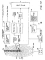
FIG.13 is a block diagram showing a schematic construction of the iris recognition system according to another embodiment of the present invention; -
FIG.14 is a block diagram showing a schematic construction of the iris recognition system according to a further embodiment of the present invention; -
FIG.15 is an illustration showing the position of the iris; and -
FIG.16 is an illustration showing a schematic construction of a prior iris recognition system. -
FIG.1 shows the whole construction of an iris recognition system, namely, an iris information acquisition apparatus according to a first embodiment of the present invention. InFIG.1 , this iris recognition system includes two wide-angle cameras zoom camera 7. The wide-angle cameras CDS circuits angle cameras CCD drivers CCDs CDS circuits control parts - Also, the system shown in
FIG.1 includes the iris acquisition controller 6 which specifies a three-dimensional position of the human eye of the subject of recognition according to an image signal inputted from thecameras zoom camera 7. - The
zoom camera 7 drives and controls asteering motor 7b to move amirror 8c so that the image pickup direction of thezoom camera 7 is directed to the human eye according to the three-dimensional position obtained as mentioned above. Also, thezoom camera 7 controls a zoom/focus motor 7a for driving a zoom lens optical system 8 to be focused on the three-dimensional position of the human eye and regulates an amount of zoom so that an iris image of the pickup subject coincides with an image pickup region of asensor 10. An iris sensor part 9 in thezoom camera 7 feeds position error and focus error information between the iris image taken by thesensor 10 and the sensor to the iris acquisition controller 6. - The iris acquisition controller 6 servocontrols each part of the camera system described above until information of the iris part described above is obtained. When the information of the iris part is obtained, this information, namely an iris code is matched with a previously registered iris code held within the iris acquisition controller 6 or held by a host computer (not shown). The matching may be performed either by the iris acquisition controller 6 or by the host computer. Also, the host computer may control each part of the camera system, or the sensor part itself may control each part by each error signal of the iris sensor part 9.
- Here, the information of the iris part which the iris acquisition controller 6 receives from the iris sensor part 9 is an iris code formed in a binary form by the sensor part 9. A construction of this iris sensor part 9 will be described in detail with reference to
FIGS.2 and3 . -
FIG.2 shows a detailed construction of the iris sensor part 9 having thesensor 10. Thissensor 10 has a pixel array pattern of polar coordinate type shown inFIG.3 , and each pixel has, for example, a shape partitioned by straight lines extending in the radial direction (r direction) and circumferential circles and light receiving areas of each pixel become larger as the pixel locates at the more outside of the radial direction. Thesensor 10 may comprise CCD image sensors or MOS type image sensors. And, the shape of this pixel array pattern is suited for each ring shape in the case of acquiring the iris code. - The outer circumferential circle L1 of the pixel array pattern has the size so as to match with the outer circumference of the iris to be taken or become slightly larger than the outer circumference of the iris, when focusing and zooming control are performed, so that necessary resolution may be obtained when the iris image is taken.
- The inner circumferential circle L2 has the size smaller than the size when the pupil becomes minimum, when the outer circumference of the iris matches with the circle L1. Since the pupil region always exists, the pixel array pattern has a region of a center part E1 surrounded by the circle L2. In this case, it is necessary to control alignment with the center of the iris and that of the pixel array pattern, since the iris image is taken by the
sensor 10 having the pixel array pattern of polar coordinate type shown inFIG.3 . - A circuit 11 (
FIG.2 ) for detecting the inner diameter of the iris detects the boundary between the iris and the pupil of the radial direction in the taken iris image through the level variation, that is, an edge detection is performed, with the result that the inner diameter of the iris is calculated. On the other hand, acircuit 12 for detecting the outer diameter of the iris detects the outer circumference of the iris in the taken iris image through the level variation, that is, the edge detection is performed, with the result that the outer diameter is calculated. Then, the detectingcircuits diameter detecting circuit 12 outputs a zoom error signal to the iris acquisition controller 6. - Also, on the assumption that the outer diameter of the iris has matched with the outer diameter of the sensor 10 (the outer circumferential circle L1), the inner
diameter detecting circuit 11 calculates the difference between the outer diameter of thesensor 10 and the detected inner diameter to calculate the number of pixels of the radial direction of thesensor 10 corresponding to said difference, and the value obtained by dividing this number of pixels by the number of ring bands (for example, 8) is fed to a weightedmean processing part 13 as the number i of pixels of the radial direction assigned to one ring. For example, the number i of pixels is set to "3" inFIG.3 . - Also, the outer diameter of the iris image may not always be matched with the outer diameter of the
sensor 10. In this case, a zoom optical system is unnecessary and the number i of pixels is calculated on the basis of the difference between the outer diameter detected by the outerdiameter detecting circuit 12 and the inner diameter detected by the innerdiameter detecting circuit 11, but the outer diameter of thesensor 10 must be larger than the outer diameter of the iris image. - The weighted
mean processing part 13 calculates a weighted mean of pixel output signals of the number i of pixels when receiving the pixel output signals from the number i of pixels. The reason why this weighted mean is calculated is because the size of the pixel becomes larger as the pixel of thesensor 10 locates at the more outside as shown inFIG.3 , so that compensation of sensitivity variation caused by the increase in the light receiving area must be performed, and influence caused by a slight error of the dividing position of each ring and a steering error due to variation in the pupil diameter is decreased by performing the weighting to the center of each ring. - The value calculated by the weighted
mean processing part 13 is fed to a high-pass filter 14 as an image output signal. The level or magnitude of high pass component of the image output signal from the high-pass filter 14 is taken out and is outputted as a focus control signal. - These steering error signal, zoom error signal and focus control signal are respectively fed to the iris acquisition controller 6. As described above, the controller 6 controls the
steering motor 7b and the zoom/focus motor 7a in thezoom camera 7 so that the iris of the image pickup subject is matched with the center of thesensor 10 as well as the outer diameter of the iris is matched with the outer circumference of thesensor 10, and the focusing is performed. - A
timing generator 20 drives adriver 21 of thesensor 10 and performs a scanning for outputting the pixel signals in the θ direction (rotational direction) every ring. When it becomes in the condition capable of taking a correct image by performing a fine adjustment by a feedback processing mentioned above, the signal outputted from each pixel is calculated or operated by the weightedmean processing part 13 to perform the weighted mean as described above and is fed to a band-pass filter 15. The band-pass filter extracts the change point in the fed pixel output signal, namely the signal change in the θ direction of the iris pattern. Further, abinary circuit 16 generates an iris code formed in a binary format, by performing conversion of the extracted signal into binary signal by a built-in comparator. Then, this iris code is fed to the iris acquisition controller 6 through alatch circuit 17. - As described above, the controller 6 compares the iris code of each ring band with the iris code previously registered in the host computer and so on so that a personal identification is performed. Also, the iris code may preferably be ciphered or encoded in order to secure security to transmit between each circuit device.
- Also, since the upper and lower portions of the iris are hidden by eyelids generally, a
circuit 18 for detecting effective range of the outer diameter of the iris detects the boundary between the eyelids and the iris through the level variation in the radial direction to calculate the upper and lower limits of the iris to be taken. - A regulating
part 19 controls, for example, thetiming generator 20 so as to invalidate the range beyond these upper and lower limits. For example, in the case of a MOS sensor, addressing in the range beyond the limits may be skipped. - Also, assuming that the image exists even in the portion hidden by the eyelids, the hide may be ignored. In this case, since a feature pattern does not exist in the eyelid portion, some degree of correlation decreases due to the matching of comparison between the eyelids when identifying the iris, but it does not matter.
- Also, by adding information on the upper and lower limits to, for example, a header of the iris code, only the effective iris codes or the effective code portions in the iris code are compared each other when comparing the iris codes and thus, influence of the eyelids may be removed. That is, only the effective portions out of the registered iris codes are used as a comparison subject. Of course, when the iris codes are registered, the eye is preferably opened wide so that the iris is not hidden by the eyelids as wide as possible.
- Further, by adding information on resolution, for example, data for indicating the number of pixels every circumference of the sensor or the number of ring bands to the header of the iris code, comparison between the iris codes obtained by the sensors having different resolutions may be readily performed.
- Of course, by adding error-detecting codes such as checksum or CRC code to, for example, a footer of the iris code, reliability on the registered iris codes may be improved. Also, the above header and footer may be added to the iris codes registered or the iris codes obtained from the
sensor 10, or both the iris codes. - Here, the comparison of the iris codes will be described in further detail. The comparison may be performed as an exclusive OR (EXOR) operation simply, unless a tilt of the eye exists, but the tilt exists generally so that the registered iris code is correlated with the detected iris code and it is determined whether a person having the detected iris code is the registered person or not, on the basis of the value with the highest correlation. This correlation may be performed by selecting the value with the highest correlation out of the values obtained when the position at θ =0° of the detected iris code is varied in the range of ±10° , for example.
- So-called "hill-climbing" method etc. is used as a method for varying and obtaining a start point of comparison, and the correlation values shifted by one point back and forth are compared each other and the climbing is performed in the direction of higher correlation. On the contrary, the iris codes may be compared immediately without a correlation processing in the case of comparison if the tilt of the θ direction of the eye to be taken can be detected.
- Also, the tilt of the eye, namely the tilt of the face may be grasped as a tilt to the horizontal plane formed by straight lines connecting bright points (P1 or P2 etc. in
FIG. 15 ) of illumination reflected in both eyes to be taken by the wide-angle cameras zoom camera 7. - Thus, by storing information, in the header of the iris code, on whether the iris code is registered with the tilt of the eye compensated or is registered without the tilt of the eye compensated for example in case of single eye registration such as a peeping method, it is unnecessary to perform a useless correlation processing so that the comparison speed may be improved.
- Also, by adding information on which eye is registered to the header, it is unnecessary to decide which eye is registered in the case of binocular registration so that the comparison speed may be improved.
- Here, output of the band-
pass filter 15 may be used, as another embodiment of thecircuits pass filter 22 and using output of thisfilter 22, the steering error signal may be outputted readily. By performing feedback of this steering error signal directly to thesteering motor 7b, steering of thezoom camera 7 may be servocontrolled directly. - That is, when the
driver 21 scans the pixel signal of thesensor 10 from the inner circumference of thesensor 10 to the outside in the radial direction, first, the output signal level from the band-pass filter 15 is almost zero regardless of an angle θ of the rotation direction as shown inFIG.4A . - Subsequently, when the pixel signal is scanned in the radial direction gradually, the output signal level indicating detection of the iris portion appears as shown in
FIG.4B , and this output signal is a signal depending on an iris pattern of the iris portion. Further, when the pixel signal is scanned in the radial direction, the output signal level is saturated to a certain level and gradually approaches inclination determined by the ratio of light receiving area of each pixel as shown inFIG.4C . - Therefore, the
circuit 11 for detecting the inner diameter of the iris detects the position on thesensor 10 as the inner diameter of the iris, when the output signal level from the band-pass filter 15 has become a certain level, for example, the output signal level has appeared or has reached saturation. Similarly, thecircuit 12 for detecting the outer diameter of the iris may detect the outer diameter of the iris through the fact that the output signal level from the band-pass filter 15 has become a predetermined level lower from the certain level or has become a level equal to or lower than a predetermied level. But, in the case of scanning to the outside in the radial direction, the scanning position, for example, immediately before the output signal level has become the certain level or lower is detected as the outer diameter of the iris. - Of course, the scanning may be performed from the outer circumference of the
sensor 10 to the inside in the radial direction. Also, it is possible to calculate the inner diameter of the iris by the scanning to the outside in the radial direction, and to calculate the outer diameter by the scanning to the inside in the radial direction, so that the inner and outer diameters may be obtained at higher speed in this manner. By using the output signal from the band-pass filter 15 thus, the inner and outer diameters of the iris may be detected readily without a complex image processing. - Further, as shown in
FIG.4C , an envelope L10 of the output signal level for the angle θ of the rotational direction may vary with respect to the angle θ of the rotational direction, and level variation in this envelope L10 means that thezoom camera 7 is not directed to the eye of the image subject. Thus, by providing the low-pass filter 22, the signal of an envelope level of the scanned image signal may be outputted and the level difference of this signal may be used as the steering error signal. In this case, also, the steering error signal may be outputted by a simple processing without using a complex image processing. In addition, the steering may be servocontrolled directly using this steering error signal. - Also, in
FIG.2 , the band-pass filter 15 and the low-pass filter 22 receive the signal through the weightedmean processing part 13 and perform a filtering, but a direct pixel signal from thesensor 10 is preferably used, after filtering, as the signal fed to the inner and outer detectingcircuits - Thus, in the first embodiment, since the
sensor 10 is constructed in pixel arrangement having the pixel array pattern of polar coordinate type shown inFIG.3 , a processing for transforming the orthogonal coordinate system into the polar coordinate system in the case of acquiring the image signal by the sensor having the pixel arrangement of orthogonal coordinate type is eliminated so that a processing speed for acquiring the iris code may be improved remarkably. - Also, although the pixel array pattern shown in
FIG.3 has the same distance between the radii of concentric circles so as to have the same length of pixel in the radial direction, the length of pixel in the radial direction may be varied according to the rate of stretching and shrinking of the iris. That is, the rate of stretching and shrinking of the iris depends on a thickness of the iris, and normally the thickness of the iris is thinner toward the center of iris and the iris is easy to stretch and shrink, so that the length of pixel of the radial direction in the pixel close to the center may be lengthened according to this nature of the iris. By varying the length of pixel of the radial direction thus, rate of recognition may be improved. - Next, a second embodiment will be described with reference to
FIG.5. FIG.5 shows a construction of aniris sensor part 9a of an iris recognition system according to the second embodiment. Theiris sensor part 9a is different from the iris sensor part 9 shown inFIG.2 in that asensor 10a is used instead of thesensor 10 and a construction of the weightedmean processing part 13 is eliminated. The other constructions are the same as those of the first embodiment and have the same reference characters as those of the first embodiment. - The
sensor 10a has pixel arrangement of a pixel array pattern of polar coordinate type like thesensor 10 and has an illuminating LED 31 (light emitting diode) which is placed on an optical axis of the sensor and illuminates the eye of human with visible light. Also, it is favorably constructed so that theLED 31 may illuminate the eye of human exactly by shifting the position of a light emitting plane of theLED 31 optically from a light receiving plane of thesensor 10a. Also, an EL (electroluminescence) device etc. other than theLED 31 may be used as illumination means. - On the contrary, the
circuit 11 for detecting the inner diameter of the iris detects the inner diameter of the iris, and the difference between this detected inner diameter and the inner circumference of thesensor 10a, namely a pupil diameter error signal is generated and is fed to the iris acquisition controller 6. - The iris acquisition controller 6 controls brightness of the
LED 31 so as to eliminate the pupil diameter error signal. That is, this control is to increase the brightness of theLED 31 when the pupil diameter is longer than the inner circumference of thesensor 10a and to decrease the brightness of theLED 31 when the pupil diameter is shorter than the inner circumference of thesensor 10a. - By the above control, the pupil diameter always matches with the inner circumference of the
sensor 10a and the outer circumference of thesensor 10a matches with the outer diameter of the iris through the steering error signal, the zoom error signal, etc. so that an iris portion of an image subject is taken with the iris portion always matching with the pixel array pattern on thesensor 10a. - Thus, the width in the radial direction of each pixel in the sensor may be determined based on necessary resolving power, so that for example, the length of the sensor in the radial direction may be divided into eight portions equally, and an iris code may be generated directly using an image pickup signal from the
sensor 10a. - Also, since division to each ring band is unnecessary and the center of the iris is determined, a recognition processing may be performed with a very simple pattern matching by previously registering an iris image. That is, since the inner and outer diameters of the iris are known, the pattern matching may be performed only by rotation at the center of the iris so that a comparison speed may be improved considerably.
- Also, In
FIG.5 , means for detecting a position error is constructed by providing an array ofphotodiodes 32 in the center of thesensor 10a so that steering of thezoom camera 7 may be controlled. That is, light emitted by theLED 31 is reflected on the surface of the eye and is received by thephotodiodes 32. The steering control is performed by using the difference between the amounts of light reception in the array position of eachphotodiode 32 as a steering error signal to feed the difference to the iris acquisition controller 6. - By using the array of the
photodiodes 32 by which the center portion E1 is utilized usefully, the difference between the amounts of light reception may be employed instead of generating the steering error signal in the inner detectingcircuit 11. Particularly, output of the array of thephotodiodes 32 is fed back to thesteering motor 7b directly and analogue servocontrol may be performed so that miniaturization and weight-saving of the system may be improved. - Further,
FIG.6 shows an example of a position relationship of the eye to thesensor 10a etc. in the apparatus ofFIG.5 . As shown inFIG.6 , illuminatinglight 33 emitted from the illuminatingLED 31 is irradiated to the eye through animage pickup lens 8b. The pupil diameter of the eye is controlled according to the intensity of this irradiated light. The image of the iris having the controlled pupil diameter is formed on thesensor 10a through theimage pickup lens 8b. Also, reflectedlight 34 indicates the situation that the reflected light from theLED 31 is irradiated on the photodiodes. - Moreover, the
photodiodes 32 described above are preferably arranged in the proximity of the optical axis of the center of thesensor 10a and may also be provided outside the outer circumference of the pixel array pattern. In this case, theLED 31 may be arranged in the outside of the optical axis pairing with thephotodiodes 32, for example. - Also, in the above-mentioned first embodiment as shown in
FIG.2 , a light emitting device for emitting invisible light such as infrared rays (IR) and thephotodiodes 32 for receiving reflected light from this light emitting device may be provided in the same position as theLED 31 and so on of the second embodiment. The means for detecting a position error is constructed by a combination of such a light emitting device and thephotodiodes 32, and the steering error signal is obtained so that positioning of the iris image and thesensor 10 may be performed. - Next, a modification of the second embodiment will be described with reference to
FIG.7 . The pixel array pattern of thesensor 10a constructing the second embodiment was the pixel array pattern of polar coordinate type like thesensor 10 and was a set of pixels each having a kind of approximately rectangular shape with the pattern divided by the straight lines of the radial direction every predetermined angle and the concentric circles every predetermined radius. - On the contrary, in this modification, a
sensor 10b has the pixel array pattern which is polar coordinate type and is a set of pixels of an approximately rhombic shape having each diagonal in the circumferential direction and the radial direction as shown inFIG.7 . But, in this pixel array pattern, since a space exists between the pixels due to each pixel with the rhombic shape, the rhombic pixels are disposed also in this space so as to effectively utilize the space. Thus, the rhombic pixels on a concentric circle deviates from the rhombic pixels on other concentric circle adjacent this in the θ direction by half pixel mutually, and resolution may be improved. Of course, a construction in which the pixels are not buried in the space between the pixels may be used. Also, the shape of the pixel is not limited to the rhombic shape. - By using the pixel array pattern having the rhombic pixels with each diagonal in the circumferential direction and the radial direction, each pixel may automatically perform weighting in sensitivity within each ring band in the radial direction, from the shape itself of the light receiving part and output the weighted value. The degree of the weighting does not increase the false rejection rate so that the false rejection rate will be suppressed even if there is some steering error, namely the center of the
sensor 10b deviates from the center of the iris image in some degree. - Also,
FIG.8 shows an example of a sensor in which each pixel has an elliptic shape. - Also,
FIG.9 shows a construction of a sensor in which each pixel has a quadrangular or square shape and has the same size. In this construction, the size of each pixel is constant regardless of a position of the radial direction of the sensor so that the difference in sensitivity of each ring band is eliminated. - Next, a third embodiment will be described with reference to
FIG.10. FIG.10 shows a construction of aniris sensor part 9b of an iris recognition system according to the third embodiment. Theiris sensor part 9b is different from theiris sensor part 9a shown inFIG.5 in that a sensor 10c which is rotated and driven is used instead of thesensor 10a. The other constructions are the same as those of the second embodiment and have the same reference characters. - In
FIG.10 , the sensor 10c is not an area sensor such as thesensors sensors sensor driving motor 40, and a detection equivalent to that of the area sensor such as thesensors timing generator 20 and so on. Also, when a pixel signal from the sensor 10c is picked up, the sensor 10c is rotating so that the pixel signal is outputted using a rotary transformer or a sliding brush and so on. - The pixels of the sensor 10c are formed in the rhombic shape having the diagonal in the radial direction like
FIG.7 . The reason why this rhombic shape is adopted is because an operation processing of the weighting is eliminated as described above. - Also, the length of the radial direction of the rhombic pixel as described above may be varied according to the rate of stretching and shrinking of the iris.
- Though the third embodiment has some complicated construction in comparison with the first and second embodiments, the sensor 10c may be constructed simply and readily in comparison with the
sensors - Also, the construction using the linear sensor may be applied to the first embodiment. In this case, each pixel of the linear sensor may not have the rhombic shape and, for example, may have the rectangular shape or the other shapes.
- Next, a fourth embodiment will be described. In the first embodiment to the third embodiment, all the image pickup signals are outputted from the
sensors pass filter 15, and the iris code formed in the binary format by thebinary circuit 16 is outputted. On the contrary, the fourth embodiment is intended to output the edge image directly by the sensor and the iris code is obtained by converting this outputted signal into the binary format by thebinary circuit 16. - Thus, in the fourth embodiment, the band-
pass filter 15 in the first embodiment to the third embodiment is eliminated, and the construction of thecircuits pass filter 14, and thecircuit 18 for detecting the effective range of the outer diameter of the iris which perform a processing on the basis of the edge image is also simplified so that a processing load may be reduced. - This construction of the sensor for directly outputting the edge image is achieved by an optical edge processing using an artificial retina lens disclosed in, for example,
Japanese Patent Laid-Open Publication No.5-297325 - Though a feature extraction of the iris is optically performed in the above example, this feature extraction may be electrically performed. For example, an outline detecting circuit which is adopted in a neurochip devised by C. A. Mead et al. in California Institute of Technology (see C. A. Mead and M. A. Mahowald, "A Silicon Model of Early Visual Processing", Neural Networks, vol.1, pp.91-97 of 1988) and imitates primary sight of the human may be used for this purpose.
-
FIG.11 shows a construction example of an iris sensor part using such a sensor. The construction shown inFIG.11 has no construction for converting an image and extracting an edge image, and in the construction, an image edge signal obtained from the sensor is formed in a binary format directly by thebinary circuit 16 and an iris code is inputted to alatch 17. Thus, no band-pass filter 15 shown in the.construction ofFIG. 5 is required. - Also, although all the sensors have the pixel array pattern of polar coordinate type in each embodiment described above, the sensor is not limited to this pattern and, for example, as shown in
FIG.12 , the sensor may have a pattern in which pixels PP are arranged in a spiral shape from the inner diameter of the iris of the sensor. - In the case of the sensor having this spiral array pattern, since the sensor functions as an one-dimensional sensor, a processing may be performed so as not to be affected by the variation in the pupil diameter, for example, by assigning serial numbers to each pixel from the outer circumference and detecting that the pixels from No.1 to No.N are the iris portion and normalizing said pixels with N. In this case, particularly, read control of each pixel is simplified. Also, even for the sensor of polar coordinate type, an one-dimensional read scan may be implemented by joining the pixels of each concentric circle in the same manner of the spiral sensor.
- Further, in the case of taking the iris image as a color sensor in which the pixels are arranged in the spiral shape with three R, G, B, addressing of each pixel forming the iris portion is facilitated.
- The construction capable of obtaining the iris code from the sensor part for the iris recognition system has been described hereinbefore. On the contrary, by incorporating a comparison circuit for comparing the detected iris code with a predetermined code into a sensor chip itself and incorporating a nonvolatile memory capable of registering the iris codes for comparison to some degree simultaneously, it may be constructed so as to output not the iris code but the comparison result, namely the identification result (for example, OK or NG) from the sensor part. In this case, this output is preferably ciphered or encoded to feed in order to secure security. By such a construction, a small identification apparatus used instead of keys of house, room, car, etc. may be implemented by only this chip, with the result that range of application may be extended.
- Also, since it is supposed that iris detection of facing type may be used, the construction may be simplified using relative parallel translation of a VAP (vertical angle variable prism) or a plurality of lenses instead of preprocessing such as alignment of the iris by the wide-angle cameras mentioned above. For example, in the case of using the VAP as shown in
FIG.13 , the iris image may be obtained by control of only an optical system including the vertical anglevariable prism 8a and azoom lens 8b and a zoom camera including aniris sensor part 9c. - Also, in
FIG.13 , the numeral 7c designates a pan/tilt motor for driving theprism 8a and the numeral 7d designates a zoom/focus motor. Also, the numeral 6a designates an iris acquisition controller and a control part of the wide-angle cameras as the iris acquisition controller 6 shown inFIG.1 is not required so that thecontroller 6a is simplified. - Further,
FIG.14 shows a construction in which acontroller 50 for driving and controlling theVAP 8a and thezoom lens 8b, amemory 51 for storing the iris code for comparison, acomparison circuit 52 for comparing the detected iris code with the iris code stored in the memory, and acipher circuit 53 are integrated into one chip. By such a construction, the cost necessary for the iris recognition system may be reduced more. Any memory device such as a hard disk unit, a magnet-optical disk unit other than the nonvolatile semiconductor memory may be used as thememory 51. - Also, it is possible to make identification determining level, that is, threshold of correlation degree of iris codes, adjustable. For example, in
Fig. 14 , adetermination value register 54 is provided. A determination value indicating an identification determining level can be stored in thedetermination value register 54, for example, from external, to designate a required correlation level. Also, it is possible to selectively supply one of a plurality of determination values from external to thedetermination value register 54. - It is also possible to provide a plurality of determination value registers and a selecting circuit for selecting one of the outputs of the registers.
- It is further possible to make the identification determination level adjustable internally, for example, based on the determination value supplied from a microprocessor in the iris recognition system. The microprocessor may generate the determination value, for example, depending on various conditions, such as brightness of the location the iris recognition system is installed, required precision of recognition, and the like.
- In the above embodiment of facing type, it may be constructed so that a three-dimensional alignment processing, which has been performed by the wide-
angle cameras zoom lens 8b is performed by approach of the subject to a predetermined distance and position from the apparatus, and only fine adjustment to perform positioning and focusing so as to direct the optical axis of thezoom lens 8b precisely toward the position of the eye using the knownVAP 8a is controlled by the iris acquisition controller or the sensor part itself. - The margin of range of such a predetermined position is about ±3 cm in a distance of 25 to 30 cm from the apparatus, so-called, a distance of distinct vision. Further, in the case of providing an illuminating LED on the optical axis of the sensor, the pupil diameter may be adjusted simultaneously if the subject is asked to look this LED.
- Also, it is obvious that a method in which a person peeps into the
zoom lens 8b from a given window etc. may be adopted without a method for facing at the distance of distinct vision. The difference between the facing method and the peeping method is that a focal length of theimage pickup lens 8b only differs. Also, thelens 8b may not always be a zoom lens and may be a lens with single focal point or a lens capable of switching the focal length. - Particularly, when a screen of a personal computer may be used in the personal recognition of electronic business, focusing may be performed even using a camera with a fixed focal point etc. by displaying an iris image and a cross line on the screen to perform steering, and displaying a message of "please approach the screen a little", for example.
- In this case, practically, the iris image is obtained by attaching an adapter lens to a normal camera mounted in the personal computer as an attachment or an option other than a method for attaching a dedicated camera to the iris recognition system, and coordinate transformation is performed by a software of the personal computer and the iris code may be obtained. Also, the iris code may be obtained by connecting a dedicated sensor and a normal CCD/MOS sensor to the iris recognition system through a half mirror and mounting both the sensors.
- Also, it is possible to construct a band-pass filter using a normal LCR and compare output of the band-pass filter with a predetermined threshold value by a comparator to form in a binary format. On the contrary, a function equivalent to the construction including the band-pass filter and the comparator may be achieved by calculating the average of outputs of continuous N pixels and comparing this average with output of a target pixel. In this case, a comparison processing may be executed without being affected by a scan speed, and also, a bandwidth of the band-pass filter may be varied by selecting the value of N, so that more flexible processing may be performed. Also, the continuous N pixels may be selected from the range including the pixels to be compared or from backward and forward of the range including the pixels to be compared.
- In the above description, the method has been mainly described in which features of the tangential direction of the iris are extracted by scanning in the tangential direction of the sensor. However, in the present invention, it is preferable that scanning is also performed in the radial direction to extract features of its direction. But, since generally a spatial frequency of the radial direction is not too high judging from the feature of the iris pattern, resolving power is reduced by taking a weighted mean of the tangential direction according to this (for example, 32 division) and the scanning in the radial direction is performed, so that redundancy may be reduced favorably.
- Further, in this case, it is unnecessary to increase the resolving power (for example, 16 division) of the radial direction too. Anyway, a circuit construction like the circuit construction used for scanning in the tangential direction may be used to perform the scanning in the radial direction. Particularly, in the case of constructing the band-pass filter by the comparison with the average of the N pixels, it may also be used as the band-pass filter in the radial direction.
- It is also possible to perform scanning only in the tangential direction. Also, it is possible to perform scanning in the tangential direction in a ring band and check if sufficient iris information is obtained to perform identification. If sufficient iris information has not yet been obtained, it is possible to scan in the tangential direction of the next ring band.
- The above-mentioned embodiments or the modifications may be combined respectively if desired. Further, the present invention may be applied to the eye of human as well as animals generally and, for example, individual identification thereof may be performed.
- As described in detail above, since the present invention uses an image pickup sensor comprising a group of pixels arranged in polar coordinates, it is unnecessary to transform an orthogonal coordinate system into a polar coordinate system in order to obtain an iris code, and the iris code may be generated at high speed without a dedicated processor, so that time necessary for personal identification may be saved and a load of a processing apparatus may be reduced.
- Also, since no apparatus for performing coordinate transformation is required, miniaturization and weight-saving of a system may be improved.
- Also, since an image of an iris portion with the same size always may be acquired by using means for regulating light, an information processing of the iris portion is facilitated and particularly, a check processing using a pattern matching may also be performed.
- Also, when a device for detecting edge information electrically or optically is used as the image pickup sensor, a load necessary for generation processing of the iris code is reduced and the processing may be performed at high speed and further, miniaturization and weight-saving of the system may be promoted.
- Further, by forming the pixels of the image pickup sensor in approximately rhombic shape, it is unnecessary to perform compensation of sensitivity and weighting, with the result that the load necessary for generation processing of the iris code may be reduced and the time may be saved.
- Still further, since pixel density of the radial direction is varied according to rate of stretching and shrinking of the iris, the decrease in recognition rate accompanying the stretching and shrinking of the iris may be prevented.
- In the foregoing specification, the invention has been described with reference to specific embodiments. However, one of ordinary skill in the art appreciates that various modifications and changes can be made without departing from the scope of the present invention as set forth in the claims below. Accordingly, the specification and figures are to be regarded in an illustrative sense rather than a restrictive sense, and all such modifications are to be included within the scope of the present invention. Therefore, it is intended that this invention encompasses all of the variations and modifications as fall within the scope of the appended claims.
Claims (51)
- An iris information sensor for obtaining an iris image signal of an iris of an eye characterized in that the iris information sensor comprises:an image pickup sensor (10) having a group of photoelectric conversion pixels arranged in concentric circles or in a spiral shape around a pole of polar coordinates; anda position error detecting means (11, 12) that detects a position error between the center of an iris image formed on the image pickup sensor (10) and the pole of the polar coordinates to provide a position error signal, wherein the position error signal is used to cause image light from an iris region of an eye to be projected on the image pickup sensor so that the center of the iris image formed on the sensor substantially matches with the pole of the polar coordinates of the sensor, to read out an iris image signal by sequentially scanning the photoelectric conversion pixels of the sensor.
- The iris information sensor as defined in claim 1, wherein the position error detecting means (11, 12) comprises a plurality of light receiving elements that receive reflected light from the eye, and wherein the position error signal is obtained based on the differences of light received by the plurality of light receiving elements.
- The iris information sensor as defined in claim 2, wherein the plurality of light receiving elements comprises an array of four photodiodes.
- The iris information sensor as defined in claim 1, wherein the position error detecting means comprises a band-pass filter (15) which receives an image signal obtained by scanning the image pickup sensor (10) in the tangential direction and which outputs a feature extraction signal, and a low-pass filter (22) which receives the feature extraction signal as an input, thereby detecting a position error between the center of an iris image formed on the image pickup sensor (10) and the pole of the polar coordinates to provide a position error signal.
- An iris information sensor as defined in claim 1, wherein said image pickup sensor (10) comprises a linear sensor in which pixels are arranged in the radial direction and rotation driving means for synchronously rotating the linear sensor around the pole of the polar coordinates, and a function equivalent to the group of the pixels of the polar coordinates is achieved by the rotation of the linear sensor through the rotation driving means.
- An iris information sensor as defined in any one of claims 1-4, wherein each pixel constructing the image pickup sensor (10) is made of a MOS sensor or a CCD sensor.
- An iris information sensor as defined in any one of claims 1-4, wherein each pixel constructing the image pickup sensor (10) is made of a device for detecting edge information electrically or optically.
- An iris information acquisition apparatus for obtaining image information of an iris region, comprising:an iris information sensor as defined in claim 1;image pickup optical system means (8) for focusing image light from an iris region of an eye onto the image pickup sensor (10);optical axis operation control means for substantially matching the center of an iris image formed on the image pickup sensor with the pole of the polar coordinates of the image pickup sensor;region determination means for determining the iris region by acquiring the inner and outer diameters of the iris according to an iris image signal obtained by the sensor; andread scan means for scanning the determined iris region in a predetermined sequence and obtaining an output value corresponding to information of the iris region.
- An iris information acquisition apparatus as defined in claim 8, wherein said read scan means for scanning the determined iris region scans the determined iris region at least in the tangential direction.
- An iris information acquisition apparatus as defined in claim 8, wherein said read scan means for scanning the determined iris region scans the determined iris region in the tangential and radial directions every given width.
- An iris information acquisition apparatus as defined in claim 8, wherein said read scan means divides the determined iris region into predetermined concentric ring bands and determines the number of pixels of the radial direction of each ring band and reads the output value corresponding to information of each ring band in which weighted mean is performed according to the number of pixels.
- An iris information acquisition apparatus as defined in claim 8, wherein said region determination means determines the iris region according to amplitude of a feature extraction signal, said feature extraction signal obtained by passing the image signal through a band-pass filter (15), said image signal obtained by scanning the image pickup sensor (10) in the tangential direction.
- An iris information acquisition apparatus as defined in claim 8, wherein said region determination means determines the iris region according to level variation in the image signal obtained by the scan in the radial direction of the image pickup sensor (10).
- An iris information acquisition apparatus as defined in claim 8, wherein said optical axis operation control means obtains the direction and size of an error between the center of the iris image formed on the image pickup sensor (10) and the pole of the polar coordinates of the sensor (10) to control a matching of the center of the iris image with the pole of the polar coordinates of the sensor (10), by further passing the feature extraction signal through a low-pass filter (22), said feature extraction signal obtained by passing the image signal through the band-pass filter (15), said image signal obtained by scanning the image pickup sensor (10) in the tangential direction.
- An iris information acquisition apparatus as defined in claim 8, further comprising illumination means (31) for irradiating illumination light (33) to the eye and a group of light receiving elements for receiving reflected light from the eye of the illumination light, said optical axis operation control means controlling a matching of the center of the iris image with the pole of the polar coordinates of the image pickup sensor according to an amount of receiving light of the group of light receiving elements.
- An iris information acquisition apparatus as defined in claim 8, further comprising iris code generation means for generating an iris code according to the output value read by the read scan means.
- An iris information acquisition apparatus as defined in claim 16, wherein said iris code generation means comprises comparison means (52) for comparing an output of a band-pass filter with a predetermined threshold value.
- An iris information acquisition apparatus as defined in claim 16, wherein said iris code generation means generates the iris code by comparing the output value of a plurality of continuous pixels with output of a target pixel.
- An iris information acquisition apparatus as defined in claim 8, wherein said optical axis operation control means controls a matching of the center of the iris image formed on the image pickup sensor by moving a mirror (8c) placed in an optical path between the eye of the iris of a subject and the sensor (10) with the pole of the polar coordinates of the sensor (10).
- An iris information acquisition apparatus as defined in claim 8, wherein said optical axis operation control means controls a matching of the center of the iris image formed on the image pickup sensor (10) by moving the sensor (10) with the pole of the polar coordinates of the sensor (10).
- An iris information acquisition apparatus as defined in claim 8, wherein said optical axis operation control means controls a matching of the center of the iris image formed on the image pickup sensor by a vertical angle variable prism (8a) placed in an optical path between the eye of the iris of a subject and the sensor with the pole of the polar coordinates of the sensor (10).
- An iris information acquisition apparatus as defined in claim 8, wherein said optical axis operation control means controls a matching of the center of the iris image formed on the image pickup sensor (10) by mutually translating a plurality of lenses (8b) placed in an optical path between the eye of the iris of a subject and the sensor (10) with the pole of the polar coordinates of the sensor (10).
- An iris information acquisition apparatus as defined in claim 8, wherein pixel density in the radial direction of each pixel of the image pickup sensor (10) corresponds to the rate of stretching and shrinking of the iris.
- An iris information acquisition apparatus for obtaining image information of an iris region of the eye, comprising:an iris information sensor as defined in claim 1;image pickup optical system means for focusing image light from the iris region onto the image pickup sensor;illumination means (31) for irradiating illumination light (33) to the eye having the iris;optical axis operation control means for substantially matching the center of an iris image formed on the sensor (10) with the pole of the polar coordinates of the sensor (10);light adjustment control means for controlling the inner diameter of the iris image formed on the sensor (10) by irradiating visible light to the eye having the iris from the illumination means (31) and adjusting an amount of the light and defining the pupil diameter; andread scan means for scanning the sensor in a predetermined sequence and reading image information of the iris region.
- An iris information acquisition apparatus as defined in claim 24, wherein said read scan means for scanning the determined iris region scans the determined iris region at least in the tangential direction.
- An iris information acquisition apparatus as defined in claim 24, wherein said read scan means for scanning the determined iris region scans the determined iris region in the tangential and radial directions.
- An iris information acquisition apparatus as defined in claim 24, wherein said image pickup optical system means includes a zoom lens (8) and keeps the outer diameter of the iris image formed on the image pickup sensor (10) by the zoom lens (8).
- An iris information acquisition apparatus as defined in claim 24, wherein each pixel of the image pickup sensor (10) has a light receiving region with an approximately rhombic shape having each diagonal in the radial and tangential directions of the polar coordinates.
- An iris information acquisition apparatus as defined in claim 24, wherein each pixel of the image pickup sensor (10) is also arranged in a region with an approximately rhombic shape surrounded by the light receiving regions with the approximately rhombic shape.
- An iris information acquisition apparatus as defined in claim 24, further comprising iris code generation means for generating an iris code according to the output value read by the read scan means.
- An iris information acquisition apparatus as defined in claim 30, wherein said iris code generation means comprises comparison means (52) for comparing an output of a band-pass filter with a predetermined threshold value.
- An iris information acquisition apparatus as defined in claim 30, wherein said iris code generation means generates the iris code by comparing the output value of a plurality of continuous pixels with output of a target pixel.
- An iris information acquisition apparatus as defined in claim 24, further comprising a group of light receiving elements for receiving reflected light from the eye of light irradiated by said illumination means, said optical axis operation control means controlling a matching of the center of the iris image with the pole of the polar coordinates of the image pickup sensor according to an amount of receiving light of the group of light receiving elements.
- An iris information acquisition apparatus as defined in claim 24, wherein said optical axis operation control means obtains the direction and size of an error between the center of the iris image formed on the image pickup sensor (10) and the pole of the polar coordinates of the sensor to control a matching of the center of the iris image with the pole of the polar coordinates of the sensor (10), by further passing the feature extraction signal through a low-pass filter (22), said feature extraction signal obtained by passing the image signal through the band-pass filter, said image signal obtained by scanning the image pickup sensor (10) in the tangential direction.
- An iris information acquisition apparatus as defined in claim 24, wherein said optical axis operation control means controls a matching of the center of the iris image formed on the image pickup sensor (10) by moving a mirror (8c) placed in an optical path between the eye of the iris of a subject and the sensor (10) with the pole of the polar coordinates of the sensor (10).
- An iris information acquisition apparatus as defined in claim 24, wherein said optical axis operation control means controls a matching of the center of the iris image formed on the image pickup sensor (10) by moving the sensor (10) with the pole of the polar coordinates of the sensor (10).
- An iris information acquisition apparatus as defined in claim 24, wherein said optical axis operation control means controls a matching of the center of the iris image formed on the image pickup sensor (10) by a vertical angle variable prism (8a) placed in an optical path between the eye of the iris of a subject and the sensor (10) with the pole of the polar coordinates of the sensor (10).
- An iris information acquisition apparatus as defined in claim 24, wherein said optical axis operation control means controls a matching of the center of the iris image formed on the image pickup sensor by mutually translating a plurality of lenses (8b) placed in an optical path between the eye of the iris of a subject and the sensor (10) with the pole of the polar coordinates of the sensor (10).
- An iris identification apparatus for acquiring an iris code representing information of an iris region of the eye and comparing and matching the acquired iris code with a previously registered iris code, comprising:an iris information sensor as defined in claim 1;image pickup optical system means for focusing image light from the iris region onto the image pickup sensor (10);optical axis operation control means for substantially matching the center of an iris image formed on the sensor (10) with the pole of the polar coordinates of the sensor (10);region determination means for determining the iris region by acquiring the inner and outer diameters of the iris according to an iris image signal obtained by the sensor (10);read scan means for dividing the determined iris region into predetermined concentric ring bands and determining the number of pixels of the radial direction of each ring band and reading the output value corresponding to information of each ring band in which weighted mean is performed according to the number of pixels;iris code generation means for generating the iris code according to the output value; andcomparison means (52) for matching the generated iris code with the previously registered iris code.
- An iris identification apparatus as defined in claim 39, wherein said matching means matches the iris region including a region hidden by the eyelids.
- An iris identification apparatus as defined in claim 39, further comprising a nonvolatile memory (51) for storing the previously registered iris code, and means for encoding or ciphering the matched result in order to secure security.
- An iris identification apparatus as defined in claim 41, further comprising means for adjusting identification determination level used when matching the generated iris code with the previously registered iris code.
- An iris identification apparatus for acquiring information of an iris region of the eye and comparing and matching the acquired information of the iris region with information of an iris region registered previously, comprising:an iris information sensor as defined in claim 1;image pickup optical system means for focusing image light from the iris region onto the image pickup sensor (10);illumination means (31) for irradiating illumination light (33) to the eye having the iris;optical axis operation control means for substantially matching the center of an iris image formed on the sensor with the pole of the polar coordinates of the sensor;light adjustment control means for controlling the inner diameter of the iris image formed on the sensor by irradiating visible light to the eye having the iris from the illumination means (31) and adjusting an amount of the light and defining the pupil diameter;read scan means for scanning the sensor (10) in the tangential and radial directions and reading the information of the iris region; andmatching means for matching the information of the iris region read by the read scan means with the information of the iris region registered previously through pattern matching.
- An iris identification apparatus as defined in claim 43, wherein said image pickup optical system means includes a zoom lens (8) and definitely keeps the outer diameter of the iris image formed on the image pickup sensor by the zoom lens.
- An iris identification apparatus as defined in claim 43, wherein said matching means matches the iris region including a region hidden by the eyelids.
- An iris identification apparatus as defined in claim 43, further comprising a nonvolatile memory (51) for storing the previously registered iris code, and means (53) for encoding or ciphering the matched result in order to secure security.
- An iris identification apparatus as defined in claim 43, further comprising means (54) for adjusting identification determination level used when said matching means performs said matching.
- An iris information sensing method for obtaining an iris image signal of an iris of an eye characterized in that the iris information sensing method comprises:providing an iris information sensor (10) which includes an image pickup sensor having a group of photoelectric conversion pixels arranged in concentric circles or in a spiral shape around a pole of polar coordinates, and which includes a position error detecting means (11, 12) that detects a position error between the center of an iris image formed on the image pickup sensor (10) and the pole of the polar coordinates to provide a position error signal; andusing the position error signal to cause image light from an iris region of an eye to be projected on the image pickup sensor (10) so that the center of the iris image formed on the sensor (10) substantially matches with the pole of the polar coordinates of the sensor (10), to read out an iris image signal by sequentially scanning the photoelectric conversion pixels of the sensor (10).
- An iris identification method for acquiring an iris code representing information of an iris region of the eye and comparing and matching the acquired iris code with a previously registered iris code, comprising the steps of:sensing iris information by using an iris information sensing method as defined in claim 48;in sensing iris information, focusing image light from the iris region on the image pickup (10) sensor through image pickup optical system means (8);substantially matching the center of an iris image formed on the sensor (10) with the pole of the polar coordinates of the sensor through (10) optical axis operation control means;determining the iris region by acquiring the inner and outer diameters of the iris according to an iris image signal obtained by the sensor (10);dividing the determined iris region into predetermined concentric ring bands and determining the number of pixels of the radial direction of each ring band and reading the output value corresponding to information of each ring band in which weighted mean is performed according to the number of pixels;generating the iris code from the output value through iris code generation means; andperforming personal identification by matching the generated iris code with the previously registered iris code.
- An iris identification method for acquiring information of an iris region of the eye and comparing and matching the acquired information of the iris region with information of an iris region registered previously, comprising the steps of:sensing iris information by using an iris information sensing method as defined in claim 48;in sensing iris information, focusing image light from the iris region on the image pickup sensor (10) through image pickup optical system means (8);irradiating illumination light (33) to the eye having the iris through illumination means;substantially matching the center of an iris image formed on the sensor (10) with the pole of the polar coordinates of the sensor (10) through optical axis operation control means;definitely controlling the inner diameter of the iris image formed on the sensor (10) by irradiating visible light to the eye having the iris from the illumination means (31) and adjusting an amount of the light (33) and defining the pupil diameter;scanning the sensor in the tangential and radial directions and reading the information of the iris region through read scan means; andperforming personal identification by matching the information of the iris region read by the read scan means with the information of the iris region registered previously through pattern matching.
- An iris identification method as defined in claim 50, wherein said image pickup optical system means includes a zoom lens and definitely keeps the outer diameter of the iris image formed on the image pickup sensor by the zoom lens.
Applications Claiming Priority (2)
| Application Number | Priority Date | Filing Date | Title |
|---|---|---|---|
| JP21974398A JP3610234B2 (en) | 1998-07-17 | 1998-07-17 | Iris information acquisition device and iris identification device |
| JP21974398 | 1998-07-17 |
Publications (4)
| Publication Number | Publication Date |
|---|---|
| EP0973122A2 EP0973122A2 (en) | 2000-01-19 |
| EP0973122A3 EP0973122A3 (en) | 2006-04-19 |
| EP0973122B1 true EP0973122B1 (en) | 2008-03-12 |
| EP0973122B8 EP0973122B8 (en) | 2008-05-28 |
Family
ID=16740302
Family Applications (1)
| Application Number | Title | Priority Date | Filing Date |
|---|---|---|---|
| EP99305613A Expired - Lifetime EP0973122B8 (en) | 1998-07-17 | 1999-07-15 | Iris Information Acquisition apparatus and iris identification apparatus |
Country Status (4)
| Country | Link |
|---|---|
| US (1) | US6526160B1 (en) |
| EP (1) | EP0973122B8 (en) |
| JP (1) | JP3610234B2 (en) |
| DE (1) | DE69938324T2 (en) |
Cited By (1)
| Publication number | Priority date | Publication date | Assignee | Title |
|---|---|---|---|---|
| WO2016006734A1 (en) * | 2014-07-09 | 2016-01-14 | 삼성전자 주식회사 | Method and device for recognizing biometric information |
Families Citing this family (127)
| Publication number | Priority date | Publication date | Assignee | Title |
|---|---|---|---|---|
| JP3610234B2 (en) * | 1998-07-17 | 2005-01-12 | 株式会社メディア・テクノロジー | Iris information acquisition device and iris identification device |
| JP3679953B2 (en) * | 1999-09-14 | 2005-08-03 | 富士通株式会社 | Personal authentication system using biometric information |
| US7009645B1 (en) * | 1999-09-30 | 2006-03-07 | Imec Vzw | Constant resolution and space variant sensor arrays |
| JP3825222B2 (en) * | 2000-03-24 | 2006-09-27 | 松下電器産業株式会社 | Personal authentication device, personal authentication system, and electronic payment system |
| JP4529263B2 (en) * | 2000-09-18 | 2010-08-25 | 沖電気工業株式会社 | Iris recognition device |
| KR100357441B1 (en) * | 2000-09-22 | 2002-10-19 | 에버미디어 주식회사 | Human iris recognition method using harr wavelet transform and lvq |
| US6792134B2 (en) * | 2000-12-19 | 2004-09-14 | Eastman Kodak Company | Multi-mode digital image processing method for detecting eyes |
| FR2819327B1 (en) * | 2001-01-10 | 2003-04-18 | Sagem | OPTICAL IDENTIFICATION DEVICE |
| JP3586431B2 (en) * | 2001-02-28 | 2004-11-10 | 松下電器産業株式会社 | Personal authentication method and device |
| KR100374708B1 (en) * | 2001-03-06 | 2003-03-04 | 에버미디어 주식회사 | Non-contact type human iris recognition method by correction of rotated iris image |
| KR100374707B1 (en) * | 2001-03-06 | 2003-03-04 | 에버미디어 주식회사 | Method of recognizing human iris using daubechies wavelet transform |
| US7095901B2 (en) * | 2001-03-15 | 2006-08-22 | Lg Electronics, Inc. | Apparatus and method for adjusting focus position in iris recognition system |
| JP2003016434A (en) * | 2001-06-27 | 2003-01-17 | Matsushita Electric Ind Co Ltd | Individual authenticating device |
| JP4838459B2 (en) * | 2001-09-17 | 2011-12-14 | キヤノン株式会社 | Ophthalmic imaging equipment |
| US20040165147A1 (en) * | 2001-11-13 | 2004-08-26 | Della Vecchia Michael A. | Determining iris biometric and spatial orientation of an iris in accordance with same |
| US7226166B2 (en) * | 2001-11-13 | 2007-06-05 | Philadelphia Retina Endowment Fund | Optimizing the properties of electromagnetic energy in a medium using stochastic parallel perturbation gradient descent optimization adaptive optics |
| US7377647B2 (en) * | 2001-11-13 | 2008-05-27 | Philadelphia Retina Endowment Fund | Clarifying an image of an object to perform a procedure on the object |
| US7775665B2 (en) * | 2001-11-13 | 2010-08-17 | Dellavecchia Michael A | Method for optically scanning objects |
| AUPR912101A0 (en) * | 2001-11-26 | 2001-12-20 | Argus Solutions Pty Ltd | Computerised identity matching management |
| KR100453943B1 (en) * | 2001-12-03 | 2004-10-20 | 주식회사 세넥스테크놀로지 | Iris image processing recognizing method and system for personal identification |
| KR100854890B1 (en) * | 2001-12-28 | 2008-08-28 | 엘지전자 주식회사 | Iris recording and recognition method using of several led for iris recognition system |
| US6665426B1 (en) * | 2002-01-29 | 2003-12-16 | West Virginia University Research Corporation | Method of biometric identification of an individual and associated apparatus |
| DE50202312D1 (en) * | 2002-04-05 | 2005-03-31 | Sis Ag Surgical Instr Systems | Apparatus and method for determining geometric measurements of an eye |
| KR20030087088A (en) * | 2002-04-26 | 2003-11-13 | 나진희 | Method of providing security using iris recognition and apparatus thereof |
| JP2004005167A (en) * | 2002-05-31 | 2004-01-08 | Matsushita Electric Ind Co Ltd | Eye position specification method and device |
| CN100337248C (en) * | 2002-11-07 | 2007-09-12 | 松下电器产业株式会社 | Personal identification method, iris registration device, iris identification device, and personal identification program |
| US20040158525A1 (en) * | 2003-02-06 | 2004-08-12 | Dort David Bogart | System and method providing contingency biometric security activation |
| US7436986B2 (en) * | 2003-03-25 | 2008-10-14 | Bausch & Lomb Incorporated | Positive patient identification |
| US7599524B2 (en) * | 2003-04-04 | 2009-10-06 | Sarnoff Corporation | Method and apparatus for providing a robust object finder |
| JP4584912B2 (en) * | 2003-04-11 | 2010-11-24 | ボシュ・アンド・ロム・インコーポレイテッド | System and method for eye data acquisition and alignment and tracking |
| CN100375121C (en) * | 2003-07-17 | 2008-03-12 | 松下电器产业株式会社 | Iris code generation method, individual authentication method, iris code entry device, individual authentication device, and individual certification program |
| US7756301B2 (en) * | 2005-01-26 | 2010-07-13 | Honeywell International Inc. | Iris recognition system and method |
| US8705808B2 (en) | 2003-09-05 | 2014-04-22 | Honeywell International Inc. | Combined face and iris recognition system |
| US8050463B2 (en) * | 2005-01-26 | 2011-11-01 | Honeywell International Inc. | Iris recognition system having image quality metrics |
| US8090157B2 (en) * | 2005-01-26 | 2012-01-03 | Honeywell International Inc. | Approaches and apparatus for eye detection in a digital image |
| US8442276B2 (en) | 2006-03-03 | 2013-05-14 | Honeywell International Inc. | Invariant radial iris segmentation |
| US8064647B2 (en) * | 2006-03-03 | 2011-11-22 | Honeywell International Inc. | System for iris detection tracking and recognition at a distance |
| US7593550B2 (en) * | 2005-01-26 | 2009-09-22 | Honeywell International Inc. | Distance iris recognition |
| US8098901B2 (en) * | 2005-01-26 | 2012-01-17 | Honeywell International Inc. | Standoff iris recognition system |
| GB0412175D0 (en) * | 2004-06-01 | 2004-06-30 | Smart Sensors Ltd | Identification of image characteristics |
| US20050281440A1 (en) * | 2004-06-18 | 2005-12-22 | Pemer Frederick A | Iris feature detection and sensor-based edge detection |
| JP2006048205A (en) * | 2004-08-02 | 2006-02-16 | Matsushita Electric Ind Co Ltd | Pupil detecting device and pupil authenticating device |
| JP2006048204A (en) * | 2004-08-02 | 2006-02-16 | Matsushita Electric Ind Co Ltd | Pupil detecting device and pupil authenticating device |
| JP4455216B2 (en) * | 2004-08-06 | 2010-04-21 | キヤノン株式会社 | Detection device |
| JP2006107028A (en) * | 2004-10-04 | 2006-04-20 | Glory Ltd | Individual authentication device and individual authentication method |
| JP4553691B2 (en) * | 2004-11-16 | 2010-09-29 | 春雄 伊藤 | Iris information sensor and iris identification device |
| JP4508842B2 (en) * | 2004-11-16 | 2010-07-21 | 春雄 伊藤 | Iris information sensor |
| US7688374B2 (en) * | 2004-12-20 | 2010-03-30 | The United States Of America As Represented By The Secretary Of The Army | Single axis CCD time gated ladar sensor |
| JP4634140B2 (en) * | 2004-12-28 | 2011-02-16 | 春雄 伊藤 | Iris identification device |
| WO2007081122A1 (en) * | 2006-01-07 | 2007-07-19 | Iritech Inc. | Iris identification system and method using mobile device with stereo camera |
| KR100729280B1 (en) | 2005-01-08 | 2007-06-15 | 아이리텍 잉크 | Iris Identification System and Method using Mobile Device with Stereo Camera |
| KR100658426B1 (en) * | 2005-01-31 | 2006-12-15 | 김신호 | Iris Zoom Camera Shooting Device By Linear Motor Driving |
| JP4851723B2 (en) * | 2005-03-04 | 2012-01-11 | 富士通株式会社 | Internal structure image acquisition device, internal structure image acquisition method, and internal structure image acquisition program |
| US20060222212A1 (en) * | 2005-04-05 | 2006-10-05 | Yingzi Du | One-dimensional iris signature generation system and method |
| US7327860B2 (en) * | 2005-05-04 | 2008-02-05 | West Virginia University | Conjunctival scans for personal identification |
| KR100786204B1 (en) * | 2006-02-27 | 2007-12-17 | 아이리텍 잉크 | Deformation-resilient iris recognition methods |
| GB2448653B (en) * | 2006-03-03 | 2011-03-23 | Honeywell Int Inc | Single lens splitter camera |
| GB2450023B (en) | 2006-03-03 | 2011-06-08 | Honeywell Int Inc | An iris image encoding method |
| JP2009529197A (en) | 2006-03-03 | 2009-08-13 | ハネウェル・インターナショナル・インコーポレーテッド | Module biometrics collection system architecture |
| WO2007101275A1 (en) | 2006-03-03 | 2007-09-07 | Honeywell International, Inc. | Camera with auto-focus capability |
| EP1991947B1 (en) * | 2006-03-03 | 2020-04-29 | Gentex Corporation | Indexing and database search system |
| KR100804798B1 (en) | 2006-03-16 | 2008-02-20 | 주식회사 에스원 | Iris scan system and the method thereof, security system and the method thereof using the same |
| WO2008039252A2 (en) | 2006-05-15 | 2008-04-03 | Retica Systems, Inc. | Multimodal ocular biometric system |
| JP2007319174A (en) * | 2006-05-30 | 2007-12-13 | Matsushita Electric Ind Co Ltd | Photographic equipment and authentication apparatus using the same |
| US20070296842A1 (en) * | 2006-06-09 | 2007-12-27 | Raymond Samuel Connell | Spiral image capture system |
| US20090167884A1 (en) * | 2006-06-09 | 2009-07-02 | Connell Jr Raymond S | Self-Similar Capture Systems |
| WO2008091401A2 (en) * | 2006-09-15 | 2008-07-31 | Retica Systems, Inc | Multimodal ocular biometric system and methods |
| US8121356B2 (en) | 2006-09-15 | 2012-02-21 | Identix Incorporated | Long distance multimodal biometric system and method |
| WO2008033784A2 (en) * | 2006-09-15 | 2008-03-20 | Retica Systems, Inc. | Long distance multimodal biometric system and method |
| KR100826876B1 (en) * | 2006-09-18 | 2008-05-06 | 한국전자통신연구원 | Iris recognition method and apparatus for thereof |
| US7970179B2 (en) * | 2006-09-25 | 2011-06-28 | Identix Incorporated | Iris data extraction |
| US7809747B2 (en) * | 2006-10-23 | 2010-10-05 | Donald Martin Monro | Fuzzy database matching |
| US9846739B2 (en) | 2006-10-23 | 2017-12-19 | Fotonation Limited | Fast database matching |
| US7733397B2 (en) * | 2006-12-22 | 2010-06-08 | Palo Alto Research Center Incorporated | Sensor surface with 3D curvature formed by electronics on a continuous 2D flexible substrate |
| JP4976156B2 (en) * | 2007-02-08 | 2012-07-18 | 富山県 | Image identification method |
| US8063889B2 (en) * | 2007-04-25 | 2011-11-22 | Honeywell International Inc. | Biometric data collection system |
| TWI337331B (en) * | 2007-07-20 | 2011-02-11 | Asustek Comp Inc | Method for finding specific pattern and method for compensating image offset |
| US20090060348A1 (en) * | 2007-08-28 | 2009-03-05 | Donald Martin Monro | Determination of Image Similarity |
| JP4996394B2 (en) * | 2007-08-31 | 2012-08-08 | 株式会社フィット・デザイン・システム | Authentication apparatus and authentication method |
| WO2009102445A2 (en) * | 2008-02-12 | 2009-08-20 | Innurvation, Inc. | Radial scanner imaging system |
| US8529441B2 (en) | 2008-02-12 | 2013-09-10 | Innurvation, Inc. | Ingestible endoscopic optical scanning device |
| US8436907B2 (en) * | 2008-05-09 | 2013-05-07 | Honeywell International Inc. | Heterogeneous video capturing system |
| US8644565B2 (en) * | 2008-07-23 | 2014-02-04 | Indiana University Research And Technology Corp. | System and method for non-cooperative iris image acquisition |
| US8213782B2 (en) | 2008-08-07 | 2012-07-03 | Honeywell International Inc. | Predictive autofocusing system |
| US8090246B2 (en) * | 2008-08-08 | 2012-01-03 | Honeywell International Inc. | Image acquisition system |
| US20100278394A1 (en) * | 2008-10-29 | 2010-11-04 | Raguin Daniel H | Apparatus for Iris Capture |
| US8317325B2 (en) * | 2008-10-31 | 2012-11-27 | Cross Match Technologies, Inc. | Apparatus and method for two eye imaging for iris identification |
| US8280119B2 (en) | 2008-12-05 | 2012-10-02 | Honeywell International Inc. | Iris recognition system using quality metrics |
| US8248499B2 (en) * | 2009-02-23 | 2012-08-21 | Gary Edwin Sutton | Curvilinear sensor system |
| US8836805B2 (en) * | 2012-07-17 | 2014-09-16 | Gary Edwin Sutton | Curved sensor system |
| US8654215B2 (en) | 2009-02-23 | 2014-02-18 | Gary Edwin Sutton | Mobile communicator with curved sensor camera |
| US8359178B2 (en) * | 2009-03-04 | 2013-01-22 | Honeywell International Inc. | Method and apparatus for identifying erroneous sensor outputs |
| JP5734954B2 (en) * | 2009-04-10 | 2015-06-17 | 三井化学株式会社 | Curable adhesive composition |
| JP5478103B2 (en) * | 2009-04-15 | 2014-04-23 | 興和株式会社 | Image processing method |
| US8630464B2 (en) | 2009-06-15 | 2014-01-14 | Honeywell International Inc. | Adaptive iris matching using database indexing |
| US8472681B2 (en) | 2009-06-15 | 2013-06-25 | Honeywell International Inc. | Iris and ocular recognition system using trace transforms |
| US10216995B2 (en) * | 2009-09-25 | 2019-02-26 | International Business Machines Corporation | System and method for generating and employing short length iris codes |
| US8452131B2 (en) * | 2009-09-25 | 2013-05-28 | International Business Machines Corporation | Iris recognition system and method |
| US8577094B2 (en) | 2010-04-09 | 2013-11-05 | Donald Martin Monro | Image template masking |
| US8742887B2 (en) | 2010-09-03 | 2014-06-03 | Honeywell International Inc. | Biometric visitor check system |
| EP2472580B1 (en) * | 2010-12-28 | 2016-08-03 | Gary Edwin Sutton | Method for making a curved sensor |
| CN102729476B (en) * | 2011-04-11 | 2014-10-15 | 研能科技股份有限公司 | Controlling method for stereo-prototyping mechanism |
| US9124798B2 (en) * | 2011-05-17 | 2015-09-01 | Eyelock Inc. | Systems and methods for illuminating an iris with visible light for biometric acquisition |
| US8937671B2 (en) | 2011-07-14 | 2015-01-20 | The United States Of America As Represented By The Secretary Of The Army | Radial readout approach to EO imagers |
| CN103605976A (en) * | 2013-11-01 | 2014-02-26 | 武汉虹识技术有限公司 | Method of using double light sources to extract iris boundary, eyelash and light spot and apparatus thereof |
| JP2015135441A (en) * | 2014-01-20 | 2015-07-27 | キヤノン株式会社 | image acquisition device |
| US9551856B2 (en) * | 2014-05-19 | 2017-01-24 | Google Inc. | MEMS-released curved image sensor |
| WO2016006831A1 (en) * | 2014-07-09 | 2016-01-14 | 주식회사 케이티앤씨 | Door-lock using iris recognition and system thereof, mobile communication terminal and network gateway used therein, and user authentication method |
| US10425814B2 (en) | 2014-09-24 | 2019-09-24 | Princeton Identity, Inc. | Control of wireless communication device capability in a mobile device with a biometric key |
| CA2969331A1 (en) | 2014-12-03 | 2016-06-09 | Princeton Identity, Inc. | System and method for mobile device biometric add-on |
| JP6482432B2 (en) * | 2015-08-21 | 2019-03-13 | キヤノン株式会社 | Drawing command processing apparatus and drawing command processing method |
| US10849490B2 (en) * | 2015-08-25 | 2020-12-01 | Indiana University Research And Technology Corporation | Systems and methods for specifying the quality of the retinal image over the entire visual field |
| WO2017123702A1 (en) | 2016-01-12 | 2017-07-20 | Princeton Identity, Inc. | Systems and methods biometric analysis |
| WO2017173228A1 (en) | 2016-03-31 | 2017-10-05 | Princeton Identity, Inc. | Biometric enrollment systems and methods |
| US10373008B2 (en) | 2016-03-31 | 2019-08-06 | Princeton Identity, Inc. | Systems and methods of biometric analysis with adaptive trigger |
| RU2615142C1 (en) * | 2016-06-15 | 2017-04-04 | Вячеслав Михайлович Смелков | Method of forming videosignal in "ring" photodetector for computer system of panoramic television surveillance |
| JP7029394B2 (en) * | 2016-07-22 | 2022-03-03 | ソニーグループ株式会社 | Image sensor and image processing system |
| CN106295536B (en) * | 2016-08-02 | 2019-05-03 | 北京无线电计量测试研究所 | Self-adapting type iris identification device and the method for carrying out iris recognition using the device |
| KR20180053108A (en) * | 2016-11-11 | 2018-05-21 | 삼성전자주식회사 | Method and apparatus for extracting iris region |
| CN107066079A (en) * | 2016-11-29 | 2017-08-18 | 阿里巴巴集团控股有限公司 | Service implementation method and device based on virtual reality scenario |
| US10607096B2 (en) | 2017-04-04 | 2020-03-31 | Princeton Identity, Inc. | Z-dimension user feedback biometric system |
| US10902104B2 (en) | 2017-07-26 | 2021-01-26 | Princeton Identity, Inc. | Biometric security systems and methods |
| RU2657453C1 (en) * | 2017-07-31 | 2018-06-14 | Вячеслав Михайлович Смелков | Method for forming video signal in a “ring” photodetector for computer system of panoramic television surveillance in conditions of complex illumination and/or complex brightness of objects |
| RU2671229C1 (en) * | 2017-10-23 | 2018-10-30 | Вячеслав Михайлович Смелков | Video signal in the television-computer system generation method for the industrial products having a circular ring form monitoring |
| CN109190505A (en) * | 2018-08-11 | 2019-01-11 | 石修英 | The image-recognizing method that view-based access control model understands |
| CN111383237B (en) * | 2018-12-29 | 2023-06-27 | Tcl科技集团股份有限公司 | Image analysis method and device and terminal equipment |
| CN111259825B (en) * | 2020-01-19 | 2023-06-02 | 成都依能科技股份有限公司 | PTZ scanning path generation method based on face recognition |
Family Cites Families (13)
| Publication number | Priority date | Publication date | Assignee | Title |
|---|---|---|---|---|
| US3050711A (en) * | 1959-02-26 | 1962-08-21 | Bell Telephone Labor Inc | Automatic character analyzer |
| US3993888A (en) * | 1974-10-29 | 1976-11-23 | Calspan Corporation | Scanning line filter |
| DE2655704C3 (en) * | 1976-12-09 | 1980-04-03 | Kronseder, Hermann, 8404 Woerth | Device for detecting foreign bodies in glass bottles |
| US4109237A (en) * | 1977-01-17 | 1978-08-22 | Hill Robert B | Apparatus and method for identifying individuals through their retinal vasculature patterns |
| US4267573A (en) | 1978-06-14 | 1981-05-12 | Old Dominion University Research Foundation | Image processing system |
| US4641349A (en) | 1985-02-20 | 1987-02-03 | Leonard Flom | Iris recognition system |
| US5063604A (en) | 1989-11-08 | 1991-11-05 | Transitions Research Corporation | Method and means for recognizing patterns represented in logarithmic polar coordinates |
| US5291560A (en) | 1991-07-15 | 1994-03-01 | Iri Scan Incorporated | Biometric personal identification system based on iris analysis |
| JPH05297972A (en) | 1992-04-17 | 1993-11-12 | Olympus Optical Co Ltd | Artificial retina device and its manufacture |
| JP3171647B2 (en) | 1992-04-17 | 2001-05-28 | オリンパス光学工業株式会社 | Artificial retina and artificial vision device |
| US5572596A (en) * | 1994-09-02 | 1996-11-05 | David Sarnoff Research Center, Inc. | Automated, non-invasive iris recognition system and method |
| US5717512A (en) | 1996-05-15 | 1998-02-10 | Chmielewski, Jr.; Thomas A. | Compact image steering and focusing device |
| JP3610234B2 (en) * | 1998-07-17 | 2005-01-12 | 株式会社メディア・テクノロジー | Iris information acquisition device and iris identification device |
-
1998
- 1998-07-17 JP JP21974398A patent/JP3610234B2/en not_active Expired - Lifetime
-
1999
- 1999-07-09 US US09/350,142 patent/US6526160B1/en not_active Expired - Lifetime
- 1999-07-15 DE DE69938324T patent/DE69938324T2/en not_active Expired - Lifetime
- 1999-07-15 EP EP99305613A patent/EP0973122B8/en not_active Expired - Lifetime
Cited By (3)
| Publication number | Priority date | Publication date | Assignee | Title |
|---|---|---|---|---|
| WO2016006734A1 (en) * | 2014-07-09 | 2016-01-14 | 삼성전자 주식회사 | Method and device for recognizing biometric information |
| US10255498B2 (en) | 2014-07-09 | 2019-04-09 | Samsung Electronics Co., Ltd. | Method and device for recognizing biometric information |
| US10679053B2 (en) | 2014-07-09 | 2020-06-09 | Samsung Electronics Co., Ltd. | Method and device for recognizing biometric information |
Also Published As
| Publication number | Publication date |
|---|---|
| EP0973122A3 (en) | 2006-04-19 |
| EP0973122B8 (en) | 2008-05-28 |
| JP2000036036A (en) | 2000-02-02 |
| JP3610234B2 (en) | 2005-01-12 |
| DE69938324T2 (en) | 2009-04-23 |
| US6526160B1 (en) | 2003-02-25 |
| DE69938324D1 (en) | 2008-04-24 |
| EP0973122A2 (en) | 2000-01-19 |
Similar Documents
| Publication | Publication Date | Title |
|---|---|---|
| EP0973122B1 (en) | Iris Information Acquisition apparatus and iris identification apparatus | |
| KR100939856B1 (en) | Personal authentication method and device | |
| US7796784B2 (en) | Personal authentication method for certificating individual iris | |
| JP2007504562A (en) | Method and apparatus for performing iris authentication from a single image | |
| JP3802892B2 (en) | Iris authentication device | |
| EP0865637A1 (en) | Wide field of view/narrow field of view recognition system and method | |
| AU2009320352A1 (en) | Apparatus and method for two eye imaging for iris identification | |
| WO2006132689A2 (en) | Method and apparatus for obtaining iris biometric information from a moving subject | |
| CN104680128B (en) | Biological feature recognition method and system based on four-dimensional analysis | |
| CN1300407A (en) | Iris identification system and method of identifying a person throagh iris recognition | |
| JP2007011667A (en) | Iris authentication device and iris authentication method | |
| JP3586456B2 (en) | Personal authentication method and personal authentication device | |
| JP2006288872A (en) | Blood vessel image input apparatus, blood vessel image constituting method, and personal authentication system using the apparatus and method | |
| KR20180134280A (en) | Apparatus and method of face recognition verifying liveness based on 3d depth information and ir information | |
| JP3808014B2 (en) | Eye image pickup device and individual authentication device | |
| KR101919090B1 (en) | Apparatus and method of face recognition verifying liveness based on 3d depth information and ir information | |
| EP3989182A2 (en) | Biometric authentication device and biometric authentication method | |
| EP4033400A1 (en) | System for acquiring iris image to enlarge iris recognition range | |
| KR20010006975A (en) | A method for identifying the iris of persons based on the reaction of the pupil and autonomous nervous wreath | |
| JP3991042B2 (en) | Personal authentication method and personal authentication device | |
| CN2508306Y (en) | Vital iris picture collecting device | |
| JP3639291B2 (en) | Personal authentication method, iris registration device, iris authentication device, and personal authentication program | |
| JP4634140B2 (en) | Iris identification device | |
| JP2009080706A (en) | Personal authentication device | |
| KR20010006976A (en) | A system for identifying the iris of persons |
Legal Events
| Date | Code | Title | Description |
|---|---|---|---|
| PUAI | Public reference made under article 153(3) epc to a published international application that has entered the european phase |
Free format text: ORIGINAL CODE: 0009012 |
|
| AK | Designated contracting states |
Kind code of ref document: A2 Designated state(s): AT BE CH CY DE DK ES FI FR GB GR IE IT LI LU MC NL PT SE |
|
| AX | Request for extension of the european patent |
Free format text: AL;LT;LV;MK;RO;SI |
|
| PUAL | Search report despatched |
Free format text: ORIGINAL CODE: 0009013 |
|
| AK | Designated contracting states |
Kind code of ref document: A3 Designated state(s): AT BE CH CY DE DK ES FI FR GB GR IE IT LI LU MC NL PT SE |
|
| AX | Request for extension of the european patent |
Extension state: AL LT LV MK RO SI |
|
| 17P | Request for examination filed |
Effective date: 20061016 |
|
| AKX | Designation fees paid |
Designated state(s): DE FR GB |
|
| 17Q | First examination report despatched |
Effective date: 20070130 |
|
| GRAP | Despatch of communication of intention to grant a patent |
Free format text: ORIGINAL CODE: EPIDOSNIGR1 |
|
| GRAS | Grant fee paid |
Free format text: ORIGINAL CODE: EPIDOSNIGR3 |
|
| GRAA | (expected) grant |
Free format text: ORIGINAL CODE: 0009210 |
|
| AK | Designated contracting states |
Kind code of ref document: B1 Designated state(s): DE FR GB |
|
| REG | Reference to a national code |
Ref country code: GB Ref legal event code: FG4D |
|
| RAP2 | Party data changed (patent owner data changed or rights of a patent transferred) |
Owner name: ITOH, HARUO |
|
| RIN2 | Information on inventor provided after grant (corrected) |
Inventor name: ITOH, HARUO |
|
| REF | Corresponds to: |
Ref document number: 69938324 Country of ref document: DE Date of ref document: 20080424 Kind code of ref document: P |
|
| ET | Fr: translation filed | ||
| PLBE | No opposition filed within time limit |
Free format text: ORIGINAL CODE: 0009261 |
|
| STAA | Information on the status of an ep patent application or granted ep patent |
Free format text: STATUS: NO OPPOSITION FILED WITHIN TIME LIMIT |
|
| 26N | No opposition filed |
Effective date: 20081215 |
|
| REG | Reference to a national code |
Ref country code: FR Ref legal event code: PLFP Year of fee payment: 18 |
|
| REG | Reference to a national code |
Ref country code: FR Ref legal event code: PLFP Year of fee payment: 19 |
|
| PGFP | Annual fee paid to national office [announced via postgrant information from national office to epo] |
Ref country code: FR Payment date: 20170727 Year of fee payment: 19 Ref country code: DE Payment date: 20170731 Year of fee payment: 19 Ref country code: GB Payment date: 20170725 Year of fee payment: 19 |
|
| REG | Reference to a national code |
Ref country code: DE Ref legal event code: R119 Ref document number: 69938324 Country of ref document: DE |
|
| GBPC | Gb: european patent ceased through non-payment of renewal fee |
Effective date: 20180715 |
|
| PG25 | Lapsed in a contracting state [announced via postgrant information from national office to epo] |
Ref country code: GB Free format text: LAPSE BECAUSE OF NON-PAYMENT OF DUE FEES Effective date: 20180715 Ref country code: DE Free format text: LAPSE BECAUSE OF NON-PAYMENT OF DUE FEES Effective date: 20190201 Ref country code: FR Free format text: LAPSE BECAUSE OF NON-PAYMENT OF DUE FEES Effective date: 20180731 |