EP0972918A2 - Continuously variable electricallly actuated control valve for high temperature applications - Google Patents
Continuously variable electricallly actuated control valve for high temperature applications Download PDFInfo
- Publication number
- EP0972918A2 EP0972918A2 EP99202294A EP99202294A EP0972918A2 EP 0972918 A2 EP0972918 A2 EP 0972918A2 EP 99202294 A EP99202294 A EP 99202294A EP 99202294 A EP99202294 A EP 99202294A EP 0972918 A2 EP0972918 A2 EP 0972918A2
- Authority
- EP
- European Patent Office
- Prior art keywords
- input
- output
- butterfly valve
- electrical actuator
- continuously variable
- Prior art date
- Legal status (The legal status is an assumption and is not a legal conclusion. Google has not performed a legal analysis and makes no representation as to the accuracy of the status listed.)
- Granted
Links
- 230000008878 coupling Effects 0.000 claims abstract description 37
- 238000010168 coupling process Methods 0.000 claims abstract description 37
- 238000005859 coupling reaction Methods 0.000 claims abstract description 37
- 230000007246 mechanism Effects 0.000 claims abstract description 23
- 238000012546 transfer Methods 0.000 claims abstract description 17
- 238000013519 translation Methods 0.000 claims abstract description 12
- 239000012530 fluid Substances 0.000 claims description 40
- 238000002485 combustion reaction Methods 0.000 claims description 14
- 238000007789 sealing Methods 0.000 claims description 7
- 230000004888 barrier function Effects 0.000 claims description 6
- 230000001105 regulatory effect Effects 0.000 claims description 5
- 239000007789 gas Substances 0.000 description 13
- 230000014616 translation Effects 0.000 description 9
- 239000003570 air Substances 0.000 description 8
- 230000001276 controlling effect Effects 0.000 description 8
- 238000006073 displacement reaction Methods 0.000 description 5
- 239000000463 material Substances 0.000 description 5
- 238000013021 overheating Methods 0.000 description 3
- 230000004044 response Effects 0.000 description 3
- OKTJSMMVPCPJKN-UHFFFAOYSA-N Carbon Chemical compound [C] OKTJSMMVPCPJKN-UHFFFAOYSA-N 0.000 description 2
- 229910000831 Steel Inorganic materials 0.000 description 2
- 229910052799 carbon Inorganic materials 0.000 description 2
- 238000010276 construction Methods 0.000 description 2
- 239000000446 fuel Substances 0.000 description 2
- 238000002955 isolation Methods 0.000 description 2
- VNWKTOKETHGBQD-UHFFFAOYSA-N methane Chemical compound C VNWKTOKETHGBQD-UHFFFAOYSA-N 0.000 description 2
- 238000000034 method Methods 0.000 description 2
- 238000012986 modification Methods 0.000 description 2
- 230000004048 modification Effects 0.000 description 2
- 230000004043 responsiveness Effects 0.000 description 2
- 239000007787 solid Substances 0.000 description 2
- 229910001220 stainless steel Inorganic materials 0.000 description 2
- 239000010935 stainless steel Substances 0.000 description 2
- 239000010959 steel Substances 0.000 description 2
- 230000002411 adverse Effects 0.000 description 1
- 239000012080 ambient air Substances 0.000 description 1
- 238000013459 approach Methods 0.000 description 1
- 230000008859 change Effects 0.000 description 1
- 238000004891 communication Methods 0.000 description 1
- 239000004020 conductor Substances 0.000 description 1
- 230000008602 contraction Effects 0.000 description 1
- 230000002950 deficient Effects 0.000 description 1
- 238000013461 design Methods 0.000 description 1
- 230000007613 environmental effect Effects 0.000 description 1
- 229910001026 inconel Inorganic materials 0.000 description 1
- 238000009434 installation Methods 0.000 description 1
- 230000007257 malfunction Effects 0.000 description 1
- 239000007769 metal material Substances 0.000 description 1
- 239000003345 natural gas Substances 0.000 description 1
- 238000007790 scraping Methods 0.000 description 1
- 230000003685 thermal hair damage Effects 0.000 description 1
Images



Classifications
-
- F—MECHANICAL ENGINEERING; LIGHTING; HEATING; WEAPONS; BLASTING
- F02—COMBUSTION ENGINES; HOT-GAS OR COMBUSTION-PRODUCT ENGINE PLANTS
- F02B—INTERNAL-COMBUSTION PISTON ENGINES; COMBUSTION ENGINES IN GENERAL
- F02B37/00—Engines characterised by provision of pumps driven at least for part of the time by exhaust
- F02B37/12—Control of the pumps
- F02B37/18—Control of the pumps by bypassing exhaust from the inlet to the outlet of turbine or to the atmosphere
- F02B37/183—Arrangements of bypass valves or actuators therefor
-
- F—MECHANICAL ENGINEERING; LIGHTING; HEATING; WEAPONS; BLASTING
- F02—COMBUSTION ENGINES; HOT-GAS OR COMBUSTION-PRODUCT ENGINE PLANTS
- F02B—INTERNAL-COMBUSTION PISTON ENGINES; COMBUSTION ENGINES IN GENERAL
- F02B37/00—Engines characterised by provision of pumps driven at least for part of the time by exhaust
- F02B37/12—Control of the pumps
- F02B37/18—Control of the pumps by bypassing exhaust from the inlet to the outlet of turbine or to the atmosphere
- F02B37/183—Arrangements of bypass valves or actuators therefor
- F02B37/186—Arrangements of actuators or linkage for bypass valves
-
- F—MECHANICAL ENGINEERING; LIGHTING; HEATING; WEAPONS; BLASTING
- F16—ENGINEERING ELEMENTS AND UNITS; GENERAL MEASURES FOR PRODUCING AND MAINTAINING EFFECTIVE FUNCTIONING OF MACHINES OR INSTALLATIONS; THERMAL INSULATION IN GENERAL
- F16K—VALVES; TAPS; COCKS; ACTUATING-FLOATS; DEVICES FOR VENTING OR AERATING
- F16K31/00—Actuating devices; Operating means; Releasing devices
- F16K31/02—Actuating devices; Operating means; Releasing devices electric; magnetic
- F16K31/04—Actuating devices; Operating means; Releasing devices electric; magnetic using a motor
- F16K31/041—Actuating devices; Operating means; Releasing devices electric; magnetic using a motor for rotating valves
- F16K31/043—Actuating devices; Operating means; Releasing devices electric; magnetic using a motor for rotating valves characterised by mechanical means between the motor and the valve, e.g. lost motion means reducing backlash, clutches, brakes or return means
- F16K31/045—Actuating devices; Operating means; Releasing devices electric; magnetic using a motor for rotating valves characterised by mechanical means between the motor and the valve, e.g. lost motion means reducing backlash, clutches, brakes or return means with torque limiters
-
- Y—GENERAL TAGGING OF NEW TECHNOLOGICAL DEVELOPMENTS; GENERAL TAGGING OF CROSS-SECTIONAL TECHNOLOGIES SPANNING OVER SEVERAL SECTIONS OF THE IPC; TECHNICAL SUBJECTS COVERED BY FORMER USPC CROSS-REFERENCE ART COLLECTIONS [XRACs] AND DIGESTS
- Y02—TECHNOLOGIES OR APPLICATIONS FOR MITIGATION OR ADAPTATION AGAINST CLIMATE CHANGE
- Y02T—CLIMATE CHANGE MITIGATION TECHNOLOGIES RELATED TO TRANSPORTATION
- Y02T10/00—Road transport of goods or passengers
- Y02T10/10—Internal combustion engine [ICE] based vehicles
- Y02T10/12—Improving ICE efficiencies
Definitions
- This invention relates generally to flow control valves and more particularly to continuously variable butterfly valves for applications in engines.
- Turbochargers affect the air fuel (A/F) ratio combusted in the cylinders of modern internal combustion engines, which includes diesel and natural gas engines.
- Turbochargers include a compressor for compressing air and a turbine for driving the compressor. The turbine operates off the exhaust flow exiting the engine. To achieve the most efficient engine performance, the boost pressure of the air delivered into the cylinders must be accurately controlled.
- One way to obtain better control over the compressor boost pressure is to control the amount of exhaust flowing through the turbine. This can be done by providing a controlled wastegate valve, which closely regulates or modulates the amount of exhaust flowing through the turbine. Design of the controlled wastegate valve must take into consideration the harsh environment in which the valve operates. The wastegate valve may be subjected to exhaust gas temperatures of up to 1 400°F (760°C). Being in close proximity to the combustion chambers, the wastegate valve also must handle the vibration and heat transfer coming from the engine block.
- a typical prior attempt includes the use of a pneumatic actuator for controlling the position of a swing valve or poppet valve.
- the swing or poppet valve regulates the flow of exhaust through an exhaust bypass in the engine turbocharger.
- pneumatic actuators can be configured to withstand the high temperature environment, they provide a slow response with a significant amount of rotational hysteresis resulting from pressure differentials between the valve and the pneumatic actuator.
- swing and poppet valves have very high gain characteristics, making precise control impracticable. These factors cause deficient control of the turbo boost pressure. This results in inefficient control of the engine turbocharger and lower efficiency for the combustion engine.
- electrically actuated butterfly valves In cool temperature applications, such as throttling ambient temperature air into an engine, there are known electrically actuated butterfly valves. Such electrically actuated butterfly valves typically have a single solid shaft, which transfers the rotational output of an electrical actuator to the butterfly valve. These electrical actuators are highly responsive which provides fast and accurate control of the butterfly valve and the low temperature gas, which flows therethrough.
- the shaft is an excellent conductor of heat and vibration, which would cause overheating, and/or failure of the electrical actuator if applied to high temperature applications, such as a wastegate flow control valve for regulating exhaust flow to a turbocharger for example.
- Rotation is transferred from the output shaft to the input shaft by a spring, roller and track mechanism which causes the input and output shafts to rotate in opposite directions.
- This connection between input and output shaft increases the complexity of the valve and allows rotational play between shafts, which in turn would decrease the responsiveness and control of the butterfly valve.
- the invention provides an apparatus in accordance with claims 1 or 3.
- the electrical actuator includes an output shaft that has a rotary position proportionally related to electric signals applied to the electrical actuator.
- the flow control valve includes an input shaft coupled to a movable valve member to regulate fluid flow through a fluid passage.
- the input shaft and output shaft are coaxially aligned and rotationally coupled by a coupling tube for direct transfer of rotary movement from the electrical actuator to the flow control valve.
- the coupling tube serves as a thermal block between the input and output shafts.
- Coupling means joins the coupling tube to the respective input and output shafts restricting heat transfer therethrough, so as to minimize heat transfer between a butterfly valve and a continuously variable electrical actuator.
- the flow control valve is a butterfly valve that includes an annular plate mounted in an annular fluid passage for regulating flow therethrough.
- the butterfly valve provides far better control over fluid flow through the fluid passage as generally compared to swing or poppet type flow control valves.
- a preferred embodiment provides an electrical actuator having a continuously variable rotational output on an output shaft and a butterfly valve with an input shaft that is connected to the output shaft to receive the continuously variable rotational output.
- An the output shaft to receive the continuously variable rotational output.
- An intermediate shaft or coupling tube couples the input and output shafts while providing a thermal block therebetween.
- the electrical actuator and butterfly valve are fixed by an intermediate housing to provide an integral electrically actuated butterfly valve component. It is a further aspect that the housing includes rows of compliance slots which serve also thermal resistors to reduce heat transfer between the butterfly valve and electrical actuator while providing axial and angular compliance therebetween.
- connection between input and output shafts allows for angular and axial translation therebetween. This allows for small angular and axial displacements and misalignments between the electrical actuator and the butterfly valve, which can be caused by thermal expansion or contraction and vibrations between the butterfly valve and the electrical actuator.
- the sealing/thrust mechanism reduces axial translations of the input shaft to prevent the annular valve plate from scraping or binding with the walls of the fluid passage.
- the torsion spring mechanisms have axial and angular flexibility to allow angular and axial translations.
- the torsion springs are preloaded to provide a rotational spring force or torque greater than that which the electrical actuator or butterfly valve will exert during normal operation to eliminate substantially all rotational hysteresis and backlash between the input and output shafts.
- a butterfly valve is mounted in an exhaust manifold of an engine to modulate exhaust flow through the turbine of an engine turbocharger.
- the rotary position of the butterfly valve is controlled by a continuously variable electrical actuator.
- Appropriate connecting means connect the rotational output of the actuator to the butterfly valve for accurate and fast control of the butterfly valve while thermally isolating the electrical actuator from high temperature fluid that flows through the butterfly valve.
- the method includes the steps of producing a continuously variable rotational output using an electrical actuator, closely and directly coupling the actuator output to the butterfly valve while thermally isolating the electrical actuator from the butterfly valve and allowing a range of axial and angular translation between the butterfly valve/input shaft and electrical actuator/output shaft.
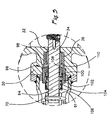
- a preferred embodiment of the present invention has been depicted as an electrically controlled butterfly valve apparatus 20 for high temperature applications.
- the preferred embodiment will be described as particularly adapted for controlling exhaust gas flow which may have a temperature of up to about 1 400°F (760°C), it should be understood from the outset that the preferred embodiment may be adapted for controlling fluid flow in other high temperature engine applications and/or in association with other applications that need thermal isolation between a valve and an electrical actuator.
- the preferred embodiment of the present invention generally includes an electrical actuator 22 that has a continuously variable output for varying the rotary position of a butterfly valve 24 or other suitable flow control valve.
- the butterfly valve 24 includes a generally cylindrical valve body 26, which can be stainless steel or other suitable material, that defines a cylindrical fluid passage 28 or other suitable annular shaped passage for passing high temperature exhaust gas.
- annular is meant to include elliptical, oval, circular and any other acceptable curve shape.
- the valve body 26 includes a drive receiving/mounting portion 30 that extends generally perpendicular to the fluid passage 28. Extending across the valve body 26 and through the drive receiving portion is a cylindrical bore 32, which extends perpendicularly across the fluid passage 28 to include diametrically opposed portions 32a, 32b.
- a solid input shaft 34 is mounted in the bore 32 for rotation relative to the valve body 26.
- the input shaft 34 extends through both diametrically opposed bore portions 32a, 32b and projects out from the drive mounting/ receiving portion 30 for receiving the continuously variable rotational output from the electrical actuator 22.
- the input shaft 34 is journalled between a pair of heat resistant carbon bearings 36 so that the input shaft 34 rotates freely relative to the valve body 26.
- An elliptical valve plate 38 or other appropriate annular shaped plate is rigidly fixed to the input shaft 34 by a pair of fasteners 40 and closely fitted in the fluid passage 28 for regulating exhaust gas flow through the fluid passage 28. As shown in a fully closed position in FIGS.1-2, 4, the annular valve plate 38 is aligned to be generally concentric with the fluid passage 28.
- the electrical actuator 22 produces the continuously variable output that is directly coupled to the input shaft 34 for fast, accurate and precise control of the butterfly valve 24 and thereby of the exhaust gas flow through the fluid passage 28.
- the electrical actuator generally includes an electrical input line 42 for receiving electric signals and an output shaft 44 that is driven to a rotational position, which is proportionally related to the electric input signals.
- the electrical actuator 22 is illustrated as a limited angle torquer (LAT) which converts a 4-20mA input current to a proportionally related rotary output position of the output shaft 44.
- LAT limited angle torquer
- the electrical actuator 22 includes an outer casing 46 that contains an inner stator assembly 48 and has a coil assembly 50 connected to the electrical input line 42.
- the output shaft 44 includes a permanent magnet armature 52, which is responsive to current applied in the coil 50.
- the electrical actuator 22 also includes a bearing housing 54 fastened to the stator 48.
- the output shaft 44 is journalled by a pair of steel ball bearings sets 56 in the bearing housing 54 and projects out of the bearing housing 54.
- the input and output shafts 34, 44 are coaxially aligned.
- the input and output shafts 34, 44 are rotationally coupled to directly transfer the continuously variable rotational output of the electrical actuator 22 to the butterfly valve 24.
- a change in rotary position of the output shaft 44 simultaneously and correspondingly modifies the rotary position of the input shaft 34 and therefore the valve plate 38.
- an intermediate coupling tube 58, or other intermediate shaft joins the input and output shafts 34, 44.
- the intermediate coupling tube 58 provides open ends 60, 61 that readily receive coaxially opposed shaft ends 63, 64 of the output shaft 44 and input shaft 34, respectively.
- each torsion spring mechanism includes a roll pin 70, or other rigid radially extending member, and a torsion spring 72.
- the roll pins 70 are pressed in corresponding holes 74 formed in the ends 63, 64 of the respective shafts 34, 44 and fixed to the shafts thereby.
- the ends of the roll pins 70 ride axially along axially extending slots 78 formed at the open ends 60,61 of the tube.
- Each torsion spring 72 is fitted over the coupling tube 58 and has an axially extending outward end 80 which cradles and engages a roll pin 70 through a tangential contact point or line.
- Each torsion spring 72 also includes an inward end 82 that engages the intermediate coupling tube 58, in this case the inward ends 82 are bent and fitted into the axial slots 78 of the coupling tube 58.
- the torsion spring mechanisms 66, 68 prevent rotational backlash between the input shaft 34 and output shaft 44. To provide this, each roll pin 70 is loaded between the torsion spring outer end 80 and one edge of the axial slot 78.
- the torsion springs 72 are preloaded to provide a rotational bias greater than the torque that the electrical actuator 22 and butterfly valve 24 will exert on the coupling tube 58 during normal operation. This prevents rotational hysteresis in the butterfly valve 24 and provides an exact response in the butterfly valve plate 38, which in turn, provides better control over the exhaust flow through the fluid passage 28.
- an outer housing tube 86 fixes the valve body 26 to the bearing housing 54 of the electrical actuator 22 to prevent rotation therebetween.
- the outer housing tube 86 contains the intermediate coupling tube 58 and projecting ends 63, 64 of the input and output shafts 34, 44.
- the outer housing tube 86 is fastened between the electrical actuator 22 and valve body 26 by sockethead cap screws 88, or other such suitable fasteners.
- the housing tube 86 also includes a plurality of access openings 89 in close proximity to the drive receiving/mounting portion 30 of the valve body 26 to allow access for disconnecting and connecting the torsion spring mechanism 68.
- high temperature exhaust gas or other fluid can be continuously applied to the fluid passage 28.
- the electrical current transmitted through line 42 to the electrical actuator 22 is controlled to selectively position the valve plate 38 as desired.
- the electrical actuator 22 is continuously variable so that the valve plate 38 may be selectively positioned and selectively held in any position between the fully open and fully closed positions.
- the position of the valve plate 38 may be updated as desired so that the valve plate 38 modulates flow.
- the speed at which flow is modulated depends on the particular application of the butterfly valve 24 and the rate at which the electrical actuator 22 responds to electrical input signals.
- the butterfly valve 24 is adapted to pass exhaust gas or other high temperature fluid that can have a temperature of up to approximately 1 400°F (760°C), while the electrical actuator 22 has an upper temperature limit of approximately 212°F (100°C) before failure or malfunction.
- the electrical actuator is protected from this adverse environment by limiting heat transfer along the control and mounting mechanism.
- the control or drive mechanism which transfers continuously variable rotational output from the electrical actuator 22 to the butterfly valve 24 is broken into separate thermally isolated drive shafts (input and output shafts 34, 44) with the coupling tube 58, an intermediate shaft or other thermal block therebetween.
- the contact areas between the coupling tube 58 and the drive shafts 34, 44 are limitated to provide at least one and preferably several thermal barriers which restricts heat transfer therebetween sufficient to prevent thermal damage to the electrical actuator 22 for the particular thermal fluid application.
- the inner diameter of the end openings of the coupling tube 58 are sized sufficiently larger than the respective outer diameter of the input shaft 34 and output shaft 44 to provide an insulating gap and minimize contact between the coupling tube 58 and the input and output shafts 34, 44.
- Each insulating gap between the tube 58 and the shafts 34, 44 serves as a primary thermal barrier preventing overheating of the electrical actuator.
- the input and output shafts 34, 44 have only a small end portion slidably fitted into the coupling tube 58 to limit heat transfer therebetween.
- Heat restriction and thermal barriers are also provided by the torsion spring mechanisms 66, 68 or other such suitable coupling means that joins the coupling tube 58 to the input and output shafts 34, 44.
- the torsion spring mechanisms 66, 68 or other coupling means minimizes the metallic contact points and/or metallic cross-sectional metallic areas between the input and output shafts.
- the torsion springs 72 provide minimum metallic contact points through tangential or other minimum contact with the roll pin 70.
- the roll pins 70 also only have a metallic tangential contact line to the wall edges of the respective slots 78.
- a preferred embodiment also uses metal materials, or other durable materials that have low thermal conductivity to further reduce heat transfer.
- the materials used for the intermediate coupling tube 58, input shaft 34 and outer housing tube 86 are preferably formed of stainless steel material, or other low thermally conductive rigid material.
- the valve plate 38 may be formed from Inconel type steel, which also has heat resistant qualities.
- Compliance slots 90 are aligned in adjacent rows 92A, 92B, 92C formed in out-of-phase alignment with one another. As seen there are multiple rows 92A, 92B, 92C of compliance slots 90, each row 92A, 92B, 92C being geometrically rotated by 120° or other appropriate angle with respect to adjacent rows 92A, 92B, 92C.
- These compliance slots 90 serve as thermal resistors because the cross sectional area of the outer housing tube 86 is greatly reduced, while the effective thermal conductive length of the outer housing tube 86 is increased.
- the access orifices 89 also increase the thermal resistance of the outer housing tube 86.
- the electrical actuator is adapted to mount in bracketing (not shown) while the butterfly valve 24 is mounted on piping conduit (shown schematically in FIG. 5).
- the installation of butterfly valve 24 and electrical actuator are preferably done at room temperature. However, during operation of the electrically at room temperature. However, during operation of the electrically controlled butterfly apparatus 20, a significant temperature differential exists between the electrical actuator 22 and the butterfly valve 24. Such temperature differentials can cause axial and angular thermal displacements and misalignments between the butterfly valve 24 and the electrical actuator 22.
- the electrically controlled butterfly valve apparatus 20 is adapted for an engine environment (as shown in FIG. 5), and engine vibrations can add additional stress to the axial and angular thermal displacements.
- the preferred embodiment provides a limited range of axial and angular translations of the input shaft 34 relative to the output shaft 44.
- angular translations refers to misalignments between the axis of the input shaft 44 and the axis of the output shaft 34.
- the end openings of the coupling tube 58 are sized large enough to permit approximately a 2° angle of angular misalignment between the axes of the input and output shafts 34, 44.
- the roll pins 70 axially ride along the axial slots 78 so that the input shaft 34 can axially translate through a range of positions in the open end 61 without creating axial stresses. Due to the resilient nature of the torsion springs 72, the connection joints between the intermediate coupling tube 58 and the shafts 34, 44 have a range of flexibility to accommodate both axial and angular translations.
- the out-of-phase compliance slots 90 also provide a limited amount of flexible compliance in the outer housing tube 86 to reduce stresses when small angular and axial displacements occur between the electrical actuator and the butterfly valve 24.
- the preferred embodiment provides a sealing/ thrust mechanism generally indicated at 96 that eliminates axial translation of the input shaft 34 to stabilize the axial position of the annular valve plate 38 relative to the fluid passage 28.
- the sealing/thrust mechanism 96 reduces vibrations and large axial translations of the input shaft 34, which could cause the valve plate 38 to bind or scrape against the walls of the fluid passage 28.
- the sealing/thrust mechanism 96 of the preferred embodiment is formed in an enlarged portion 98 of the cylindrical bore 32.
- the sealing/thrust mechanism 96 includes an inner sleeve 100 which rides slidably over the input shaft 34 and an outer sleeve 102 that is axially fastened to the valve body 26 and is disposed concentrically over the inner sleeve 100.
- the outer sleeve 102 and the inner sleeve 100 form a spring chamber 104.
- a spring 106 is coaxially disposed in the spring chamber to seat the inner sleeve 100 against a seal washer 110.
- the input shaft 34 also defines a shoulder 108, which receives the axial spring 106 force to stabilize the position of the input shaft 34 and thereby the annular valve plate 38.
- Compressed between the shoulder 108 and the inner sleeve 100 is a temperature resistant carbon seal washer 110 which acts as a seal to prevent fluid leakage through the bore 32.
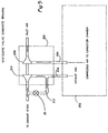
- the electrically actuated butterfly valve apparatus 20 is configured as a wastegate in fluid communication with a turbocharger 200 of an internal combustion engine 202.
- the internal combustion engine has a compressed air inlet conduit 204 leading to the combustion chambers of the engine 202 and an exhaust gas outlet conduit 206 for discharge.
- the turbocharger 200 includes a compressor 208, which compresses air to the inlet conduit 204 and a turbine 210 which powers the compressor 208.
- the turbine 210 is driven by exhaust gas flow through the outlet conduit 206.
- an exhaust gas bypass line 212 which is controlled by the electrically controlled butterfly apparatus 20 that is shown in FIGS. 1-3.
- the bypass 212 is disposed in fluidic parallel with the outlet conduit 206 to divert exhaust gas flowing to the turbine 210. This controls the operating speed of the compressor 208 and thereby the boost pressure provided by the turbocharger 200 to the engine 202.
- the exhaust gas flow through the bypass 212 may have temperatures of up to approximately 1 400°F (760°C) depending upon the particular type of engine.
- the electrically controlled butterfly valve apparatus 20 has thermal advantages in any application where the fluid being controlled is greater than the temperature limit of the electrical actuator 22, particularly where fluid temperatures though the butterfly approach 100°F (38°C) more than the temperature limit of the electrical actuator (which as was mentioned, is limited to about 212°F (100°C)), when the possibility of overheating the electrical actuator 22 with only a single shaft becomes very significant.
- this valve may also be used in controlling compressor 208 bypass and/or turbine 210 bleed operations in internal combustion engines 202.
- the temperature is much less than 1 400°F (760°C), although compressed air has a higher temperature than ambient air.
- the input and output shafts 34, 44 may be directly coupled through one torsion spring mechanism or other rotational coupler thereby eliminating the intermediate coupling tube.
- the electrically controlled butterfly valve apparatus 20 may also be used in turbine engine applications (not to be confused with turbochargers of internal combustion engines) for modulating fluid flow therein or possibly other such situations which desire an accurate and responsive valve to operate with high temperature fluids.
Landscapes
- Engineering & Computer Science (AREA)
- General Engineering & Computer Science (AREA)
- Mechanical Engineering (AREA)
- Chemical & Material Sciences (AREA)
- Combustion & Propulsion (AREA)
- Electrically Driven Valve-Operating Means (AREA)
- Supercharger (AREA)
- Magnetically Actuated Valves (AREA)
- Lift Valve (AREA)
- Flow Control (AREA)
- Electrical Control Of Air Or Fuel Supplied To Internal-Combustion Engine (AREA)
- Control Of Temperature (AREA)
- Valve Device For Special Equipments (AREA)
Abstract
Description
Claims (12)
- An apparatus for modulating the flow of high temperature fluid comprising:a butterfly valve (24) having a valve body (26), an annular valve plate (38) and an input shaft (34), the valve body (26) defining a fluid passage (28) for interposition along the fluid conduit, the annular valve plate (38) being coupled to the input shaft (34) and mounted for continuously variable rotation in the fluid passage (28);an electrical actuator (22) having a continuously variable rotational output on an output shaft (44);a coupling tube (58) joining the output shaft (44) and the input shaft (34) to transfer the continuously variable output from the electrical actuator (22) to the butterfly valve (24), the coupling tube (58) having at least one thermal barrier imposed therein to reduce heat transfer between the input and output shafts (34, 44); anda housing (86) fixing the valve body (26) with the electrical actuator (22) to prevent rotation therebetween.
- An apparatus in accordance with claim 1, characterized in that the butterfly valve (24) is connected to an exhaust manifold of an internal combustion engine (202) to modulate exhaust gas flow through an engine turbocharger (220).
- An apparatus for regulating the boost pressure to a turbocharger (200) of an internal combustion engine (202), the turbocharger (200) including a turbine (210) powering a compressor (208), the turbine (210) connected to an exhaust manifold (206) of the engine (202) to received exhaust flow therefrom, comprising:a butterfly valve (24) having a valve body (26) and an annular valve plate (38), the valve body (26) defining an exhaust passage (28), the exhaust passage (28) being connected to the exhaust manifold (206) for modulating exhaust flow through the turbine (210), the annular valve plate (38) being mounted for continuously variable rotation in the exhaust passage (28) for modulating flow therethrough;an electrical actuator (22) having a continuously variable rotational output; andmeans for connecting the continuously variable rotational output to the annular valve plate (38) to control the rotary position of the valve plate (38) with respect to the valve body (26) while thermally isolating the electrical actuator (22) from the butterfly valve (24).
- An apparatus in accordance with claim 3, characterized by a housing (86) fixing the valve body (26) to the electrical actuator (22) to prevent rotation therebetween.
- An apparatus in accordance with claim 3 or 4, characterized in that the electrical actuator (22) comprises an output shaft (44), said continuously variable rotational output being transmitted to the output shaft (44), and wherein the butterfly valve (24) further comprises an input shaft (34) coupled to the annular plate (38), the input shaft (34) being rotationally coupled to said output shaft (44).
- An apparatus in accordance with claim 5, characterized in that said input and output shafts (34, 44) are coaxially aligned, and further including a coupling tube (58) having first and second ends, wherein the first and second ends (60, 61) are rotationally coupled to the output and input shafts (44, 34), respectively.
- An apparatus in accordance with claim 1 or 6, characterized in that the input and output shafts (34, 44) are slidably fitted into respective ends (61, 60) of the coupling tube (58) to allow a limited range of axial and angular translation between the input and output shafts (34, 44) to allow for the thermal expansion in butterfly valve (24) during application of high temperature fluid through the fluid passage.
- An apparatus in accordance with claims 1, 6 or 7, characterized by a pair of torsion spring mechanisms (66, 68), one at each end of the coupling tube (58) linking the input and output shafts (34, 44) to the coupling tube (58), the torsion spring mechanisms (66, 68) being preloaded to a torque greater than that which the butterfly valve (24) and electrical actuator (22) will exert during operation to thereby minimize rotational hysteresis between input and output shafts (34, 44).
- An apparatus in accordance with claims 1, 6, 7 or 8, characterized by a sealing/thrust mechanism (96) on the input shaft (34) for reducing axial translation of the input shaft (34) to maintain relatively constant the axial position of the annular valve plate (38) relative to the valve body (26).
- An apparatus in accordance with claims 1 or 6 to 9, characterized in that the coupling tube (58) has first and second ends (61, 60) slidably receiving the input and output shafts (34, 44) respectively, the first and second ends (61, 60) have minimum contact with the input and output shafts (34, 44) to provide first and second primary thermal barriers, respectively.
- An apparatus in accordance with claims 1 or 6 to 10, characterized in that the first and second ends (61, 60) define axially extending first and second slots (78), the input shaft (34) providing a first rigid member extending radially into the first slot (78), the output shaft (44) providing a second rigid member extending radially into the second slot (78), third and fourth thermal barriers disposed between the rigid members and the slots, respectively.
- An apparatus in accordance with claims 1 or 4 to 11, characterized in that the housing (86) is an outer tube surrounding the coupling tube (58), the input shaft (34) and the output shaft (44), the outer tube defining a plurality of apertures (90) selectively arranged to provide increased thermal resistance.
Applications Claiming Priority (2)
| Application Number | Priority Date | Filing Date | Title |
|---|---|---|---|
| US118156 | 1987-11-06 | ||
| US09/118,156 US6079210A (en) | 1998-07-16 | 1998-07-16 | Continuously variable electrically actuated flow control valve for high temperature applications |
Publications (3)
| Publication Number | Publication Date |
|---|---|
| EP0972918A2 true EP0972918A2 (en) | 2000-01-19 |
| EP0972918A3 EP0972918A3 (en) | 2003-05-14 |
| EP0972918B1 EP0972918B1 (en) | 2005-09-21 |
Family
ID=22376818
Family Applications (1)
| Application Number | Title | Priority Date | Filing Date |
|---|---|---|---|
| EP99202294A Expired - Lifetime EP0972918B1 (en) | 1998-07-16 | 1999-07-13 | Continuously variable electricallly actuated control valve for high temperature applications |
Country Status (6)
| Country | Link |
|---|---|
| US (1) | US6079210A (en) |
| EP (1) | EP0972918B1 (en) |
| JP (1) | JP4442954B2 (en) |
| AT (1) | ATE305086T1 (en) |
| DE (1) | DE69927323T2 (en) |
| NO (1) | NO993447L (en) |
Cited By (23)
| Publication number | Priority date | Publication date | Assignee | Title |
|---|---|---|---|---|
| EP1473497A1 (en) * | 2003-04-30 | 2004-11-03 | Invensys Building Systems, Inc. | Thermal isolator and controlled valve employing same |
| EP1522691A1 (en) * | 2003-10-08 | 2005-04-13 | Aisin Seiki Kabushiki Kaisha | Exhaust gas sealing system for turbocharger |
| WO2006128616A1 (en) * | 2005-06-02 | 2006-12-07 | Borgwarner Inc. | Adjusting shaft arrangement of a turbocharger |
| WO2008014043A1 (en) * | 2006-07-24 | 2008-01-31 | Emcon Technologies Llc. | Thermally isolated valve actuator |
| WO2008121432A1 (en) * | 2007-04-02 | 2008-10-09 | Emcon Technologies Llc | Hybrid exhaust valve assembly |
| DE10215361B4 (en) * | 2002-04-08 | 2008-12-24 | Continental Automotive Gmbh | Method for modeling a mass flow through a bypass to an exhaust gas turbocharger |
| WO2009056197A1 (en) | 2007-10-29 | 2009-05-07 | Volkswagen Aktiengesellschaft | Internal combustion engine comprising an exhaust-gas turbocharger and a charge-air cooler |
| US7536990B2 (en) | 2006-11-21 | 2009-05-26 | Emcon Technologies Llc | Hybrid exhaust valve assembly |
| WO2010103249A1 (en) * | 2009-03-13 | 2010-09-16 | Faurecia Systemes D'echappement | Exhaust line valve |
| US8490395B2 (en) | 2004-12-14 | 2013-07-23 | Borgwarner Inc. | Turbine regulating valve system |
| WO2013139762A1 (en) * | 2012-03-21 | 2013-09-26 | Mahle International Gmbh | Wastegate valve device |
| WO2013162886A1 (en) * | 2012-04-27 | 2013-10-31 | General Electric Company | Rotary vane actuator operated air valves |
| WO2014139501A1 (en) * | 2013-03-10 | 2014-09-18 | Kohlhage Automotive GmbH & Co. KG | Exhaust-gas system |
| EP2434130A3 (en) * | 2010-09-22 | 2015-06-24 | Hamilton Sundstrand Corporation | Turbine starter valve |
| EP2905445A1 (en) * | 2014-02-07 | 2015-08-12 | Roller Bearing Company of America, Inc. | Turbocharger wastegate actuator high temperature rod end with a spherical bearing and a method for operating the actuator |
| DE102014104578A1 (en) * | 2014-04-01 | 2015-10-01 | Pierburg Gmbh | Valve device for an internal combustion engine |
| DE102014104577A1 (en) * | 2014-04-01 | 2015-10-01 | Pierburg Gmbh | Exhaust flap device for an internal combustion engine |
| WO2016097678A1 (en) * | 2014-12-19 | 2016-06-23 | Norgren Limited | Valve with bearing isolation |
| WO2018193182A1 (en) * | 2017-04-21 | 2018-10-25 | Valeo Systemes De Controle Moteur | Rotation-drive device having an elastic return member and fluid circulation valve comprising the same |
| US10145310B2 (en) | 2014-04-01 | 2018-12-04 | Pierburg Gmbh | Flap device for an internal combustion engine |
| WO2018234096A1 (en) * | 2017-06-22 | 2018-12-27 | Man Diesel & Turbo Se | WASTEGATE VALVE ACTUATOR SYSTEM OF EXHAUST SYSTEM AND EXHAUST SYSTEM |
| EP3431735A1 (en) * | 2017-07-20 | 2019-01-23 | Pierburg GmbH | Flap device |
| US10208658B2 (en) | 2013-10-15 | 2019-02-19 | Roller Bearing Company Of America, Inc. | Turbocharger wastegate actuator high temperature rod end with a spherical bearing and a method for operating the actuator |
Families Citing this family (46)
| Publication number | Priority date | Publication date | Assignee | Title |
|---|---|---|---|---|
| DE59905651D1 (en) * | 1999-07-16 | 2003-06-26 | Siemens Ag | throttle body |
| US6467587B2 (en) * | 2001-02-26 | 2002-10-22 | Woodward Governor Company | Energy absorbing shock mechanism for reducing impact and rotary actuator incorporating same |
| US6672280B2 (en) | 2001-03-09 | 2004-01-06 | Visteon Global Technologies, Inc. | Torsion spring assembly for electronic throttle |
| US6681799B2 (en) * | 2001-09-21 | 2004-01-27 | Siemens Vdo Automotive, Inc. | Exhaust gas regulator including an overmolded housing |
| US6575149B2 (en) * | 2001-09-21 | 2003-06-10 | Siemens Vdo Automotive, Incorporated | Exhaust gas regulator including a non-contact sensor |
| DE102004047180B4 (en) * | 2004-09-29 | 2014-07-17 | Robert Bosch Gmbh | Charging device with load control on internal combustion engines |
| USD524821S1 (en) * | 2004-10-21 | 2006-07-11 | Kohler Co. | Coupler |
| USD524822S1 (en) * | 2004-10-21 | 2006-07-11 | Kohler Co. | Coupler |
| US7740228B2 (en) * | 2006-08-09 | 2010-06-22 | Hamilton Sundstrand Corporation | Valve assembly including a torsion spring coupling a valve shaft and actuator shaft |
| WO2008115773A2 (en) * | 2007-03-20 | 2008-09-25 | Borgwarner Inc. | Combustion engine breathing system valve module |
| US8480054B2 (en) * | 2008-05-30 | 2013-07-09 | Woodward, Inc. | Tortionally stiff, thermally isolating shaft coupling with multiple degrees of freedom to accommodate misalignment |
| DE102009061265B3 (en) | 2009-03-10 | 2022-07-14 | Küster Holding GmbH | Exhaust flap device for motor vehicles and method for installing an exhaust flap device |
| DE102009011951B4 (en) * | 2009-03-10 | 2013-08-22 | Küster Holding GmbH | Exhaust flap device for motor vehicles and method for assembling an exhaust valve device |
| DE102009016597C5 (en) | 2009-04-08 | 2023-03-23 | Küster Holding GmbH | Exhaust flap drive for a motor vehicle |
| DE102010013367A1 (en) * | 2010-03-30 | 2011-10-06 | Bayerische Motoren Werke Aktiengesellschaft | Exhaust manifold turbocharger assembly for an automotive internal combustion engine |
| US20120006020A1 (en) * | 2010-04-10 | 2012-01-12 | Karim Wahdan | Methods and systems for powering a compressor turbine |
| KR101452019B1 (en) * | 2010-08-30 | 2014-10-21 | 현대중공업 주식회사 | Duo Disc Butterfly Valve for a Diesel Engine Turbocharger Cut-off |
| US20120104300A1 (en) * | 2010-10-29 | 2012-05-03 | Dowd Peter J | Composite seal |
| DE102011102018A1 (en) * | 2011-05-19 | 2012-11-22 | Friedrich Boysen Gmbh & Co. Kg | Valve device used in gas exhaust system for motor vehicle, has valve connected with actuator by connectors and resilient coupling that is formed of sleeve-shape and provided with bellows |
| DE102011107088C5 (en) * | 2011-07-11 | 2019-10-02 | Friedrich Boysen Gmbh & Co. Kg | Valve device |
| DE102012203624B4 (en) * | 2012-03-07 | 2023-08-10 | Borgwarner Inc. | Exhaust gas turbocharger for use with an internal combustion engine |
| DE112013002087T5 (en) | 2012-05-17 | 2015-01-15 | Borgwarner Inc. | Thermally insulating VTG lever and heat-insulating VTG connection |
| KR101362058B1 (en) * | 2012-12-17 | 2014-02-12 | 기아자동차 주식회사 | Exhaust gas recirculation valve for vehicle |
| US10018157B2 (en) | 2013-03-14 | 2018-07-10 | Ford Global Technologies, Llc | Methods and systems for boost control |
| US9309837B2 (en) | 2013-08-13 | 2016-04-12 | Ford Global Technologies, Llc | Methods and systems for EGR control |
| US9682685B2 (en) | 2013-08-13 | 2017-06-20 | Ford Global Technologies, Llc | Methods and systems for condensation control |
| US9151219B2 (en) | 2013-08-13 | 2015-10-06 | Ford Global Technologies, Llc | Methods and systems for surge control |
| US9174637B2 (en) | 2013-08-13 | 2015-11-03 | Ford Global Technologies, Llc | Methods and systems for torque control |
| US9279374B2 (en) | 2013-08-13 | 2016-03-08 | Ford Global Technologies, Llc | Methods and systems for surge control |
| US9303557B2 (en) | 2013-08-13 | 2016-04-05 | Ford Global Technologies, Llc | Methods and systems for EGR control |
| US9080506B2 (en) | 2013-08-13 | 2015-07-14 | Ford Global Technologies, Llc | Methods and systems for boost control |
| US9091202B2 (en) | 2013-08-13 | 2015-07-28 | Ford Global Technologies, Llc | Methods and systems for boost control |
| US9109505B2 (en) | 2013-08-13 | 2015-08-18 | Ford Global Technologies, Llc | Methods and systems for condensation control |
| US9261051B2 (en) | 2013-08-13 | 2016-02-16 | Ford Global Technologies, Llc | Methods and systems for boost control |
| US9309836B2 (en) | 2013-08-13 | 2016-04-12 | Ford Global Technologies, Llc | Methods and systems for boost control |
| DE102013015138A1 (en) * | 2013-09-13 | 2015-03-19 | Man Truck & Bus Ag | Device for controlling a throttle valve, in particular a throttle valve of an intake system of an internal combustion engine |
| DE112014005448A5 (en) | 2013-11-30 | 2016-08-11 | Kohlhage Automotive GmbH & Co. KG | Valve unit, such as exhaust flap unit for motor vehicles |
| US9759135B2 (en) | 2014-04-04 | 2017-09-12 | Ford Global Technologies, Llc | Method and system for engine control |
| US9551276B2 (en) | 2014-08-14 | 2017-01-24 | Ford Global Technologies, Llc | Methods and systems for surge control |
| FR3032253B1 (en) * | 2015-02-04 | 2017-01-20 | Mmt Sa | ELECTRO-CONTROLLED VALVE FOR HOT FLUID |
| JP6597031B2 (en) * | 2015-07-31 | 2019-10-30 | いすゞ自動車株式会社 | Exhaust gas recirculation device |
| DE202016101720U1 (en) * | 2016-03-31 | 2017-07-03 | Jasta-Armaturen Gmbh & Co. Kg | butterfly valve |
| DE102018204431B4 (en) * | 2018-03-22 | 2020-06-04 | smk systeme metall kunststoff gmbh & co. kg | Vibration-optimized flap valve and exhaust flap system with such a flap valve |
| DE102018214069A1 (en) * | 2018-08-21 | 2020-02-27 | Continental Automotive Gmbh | Valve for controlling exhaust gas or fresh air in a drive unit of a motor vehicle or generator |
| WO2020070980A1 (en) | 2018-10-05 | 2020-04-09 | 株式会社Ihi | Bearing structure |
| US12123339B1 (en) * | 2023-12-28 | 2024-10-22 | Garrett Transportation I Inc. | Turbine wastegate linkage assembly |
Family Cites Families (11)
| Publication number | Priority date | Publication date | Assignee | Title |
|---|---|---|---|---|
| US2753147A (en) * | 1953-05-14 | 1956-07-03 | Welge Victor | Valve for exhaust braking |
| DE2802038C2 (en) * | 1978-01-18 | 1982-06-16 | Lorenz 7208 Spaichingen Mattes | Shut-off device for smoke exhaust pipe |
| US4380246A (en) * | 1981-03-20 | 1983-04-19 | Dayco Corporation | Butterfly valve and method of making same |
| US4819696A (en) * | 1988-01-22 | 1989-04-11 | Usui Kokusai Sangyo Kabushiki Kaisha | Slide type exhaust brake system |
| DE4040760A1 (en) * | 1989-12-26 | 1991-06-27 | Aisan Ind | EXHAUST FLOW VALVE FOR AN INTERNAL COMBUSTION ENGINE |
| US5085401A (en) * | 1990-07-16 | 1992-02-04 | H. L. Ledeen Associates | Low power valve actuator |
| GB9323340D0 (en) * | 1993-11-11 | 1994-01-05 | Allied Signal Ltd | Turbochargers for internal combustion engines |
| US5638926A (en) * | 1994-06-27 | 1997-06-17 | United States Gear Corporation | Vehicle engine brake |
| JPH09511813A (en) * | 1995-02-10 | 1997-11-25 | フィリップス エレクトロニクス ネムローゼ フェンノートシャップ | Device for actuating the control member |
| CA2238440C (en) * | 1995-12-15 | 2004-07-27 | Kimberly-Clark Worldwide, Inc. | High temperature, high speed rotary valve |
| US5740785A (en) * | 1997-06-09 | 1998-04-21 | Southwest Research Institute | Two way-high pressure loop, exhaust gas recirculation valve |
-
1998
- 1998-07-16 US US09/118,156 patent/US6079210A/en not_active Expired - Lifetime
-
1999
- 1999-07-13 EP EP99202294A patent/EP0972918B1/en not_active Expired - Lifetime
- 1999-07-13 NO NO993447A patent/NO993447L/en unknown
- 1999-07-13 AT AT99202294T patent/ATE305086T1/en not_active IP Right Cessation
- 1999-07-13 DE DE69927323T patent/DE69927323T2/en not_active Expired - Lifetime
- 1999-07-16 JP JP20347399A patent/JP4442954B2/en not_active Expired - Fee Related
Cited By (38)
| Publication number | Priority date | Publication date | Assignee | Title |
|---|---|---|---|---|
| DE10215361B4 (en) * | 2002-04-08 | 2008-12-24 | Continental Automotive Gmbh | Method for modeling a mass flow through a bypass to an exhaust gas turbocharger |
| US7070165B2 (en) | 2003-04-30 | 2006-07-04 | Invensys Building Systems, Inc. | Thermal isolator and controlled valve employing same |
| EP1473497A1 (en) * | 2003-04-30 | 2004-11-03 | Invensys Building Systems, Inc. | Thermal isolator and controlled valve employing same |
| EP1522691A1 (en) * | 2003-10-08 | 2005-04-13 | Aisin Seiki Kabushiki Kaisha | Exhaust gas sealing system for turbocharger |
| US7080510B2 (en) | 2003-10-08 | 2006-07-25 | Aisin Seiki Kabushiki Kaisha | Exhaust gas sealing system for turbocharger |
| US8490395B2 (en) | 2004-12-14 | 2013-07-23 | Borgwarner Inc. | Turbine regulating valve system |
| US8172513B2 (en) | 2005-06-02 | 2012-05-08 | Borgwarner Inc. | Adjusting shaft arrangement of a turbocharger |
| WO2006128616A1 (en) * | 2005-06-02 | 2006-12-07 | Borgwarner Inc. | Adjusting shaft arrangement of a turbocharger |
| WO2008014043A1 (en) * | 2006-07-24 | 2008-01-31 | Emcon Technologies Llc. | Thermally isolated valve actuator |
| US7581710B2 (en) | 2006-07-24 | 2009-09-01 | Emcon Technologies Llc | Thermally isolated actuator with temporary contacting linkage for an exhaust valve |
| US7536990B2 (en) | 2006-11-21 | 2009-05-26 | Emcon Technologies Llc | Hybrid exhaust valve assembly |
| WO2008121432A1 (en) * | 2007-04-02 | 2008-10-09 | Emcon Technologies Llc | Hybrid exhaust valve assembly |
| CN101842565A (en) * | 2007-10-29 | 2010-09-22 | 大众汽车有限公司 | Internal combustion engine with exhaust gas turbocharger and charge air cooler |
| US8051842B2 (en) | 2007-10-29 | 2011-11-08 | Volkswagen Aktiengesellschaft | Internal combustion engine with an exhaust-gas turbocharger and a charge-air cooler and method for operating an internal combustion engine |
| WO2009056197A1 (en) | 2007-10-29 | 2009-05-07 | Volkswagen Aktiengesellschaft | Internal combustion engine comprising an exhaust-gas turbocharger and a charge-air cooler |
| CN101842565B (en) * | 2007-10-29 | 2016-05-04 | 大众汽车有限公司 | With the internal combustion engine of exhaust-driven turbo-charger exhaust-gas turbo charger and charger-air cooler |
| WO2010103249A1 (en) * | 2009-03-13 | 2010-09-16 | Faurecia Systemes D'echappement | Exhaust line valve |
| FR2943114A1 (en) * | 2009-03-13 | 2010-09-17 | Faurecia Sys Echappement | VALVE FOR EXHAUST LINE |
| EP2434130A3 (en) * | 2010-09-22 | 2015-06-24 | Hamilton Sundstrand Corporation | Turbine starter valve |
| WO2013139762A1 (en) * | 2012-03-21 | 2013-09-26 | Mahle International Gmbh | Wastegate valve device |
| US9506398B2 (en) | 2012-03-21 | 2016-11-29 | Mahle International Gmbh | Wastegate valve device |
| WO2013162886A1 (en) * | 2012-04-27 | 2013-10-31 | General Electric Company | Rotary vane actuator operated air valves |
| WO2014139501A1 (en) * | 2013-03-10 | 2014-09-18 | Kohlhage Automotive GmbH & Co. KG | Exhaust-gas system |
| US10208658B2 (en) | 2013-10-15 | 2019-02-19 | Roller Bearing Company Of America, Inc. | Turbocharger wastegate actuator high temperature rod end with a spherical bearing and a method for operating the actuator |
| EP2905445A1 (en) * | 2014-02-07 | 2015-08-12 | Roller Bearing Company of America, Inc. | Turbocharger wastegate actuator high temperature rod end with a spherical bearing and a method for operating the actuator |
| DE102014104577A1 (en) * | 2014-04-01 | 2015-10-01 | Pierburg Gmbh | Exhaust flap device for an internal combustion engine |
| DE102014104577B4 (en) * | 2014-04-01 | 2020-02-06 | Pierburg Gmbh | Exhaust flap device for an internal combustion engine |
| DE102014104578B4 (en) * | 2014-04-01 | 2020-02-06 | Pierburg Gmbh | Flap device for an internal combustion engine |
| US10294896B2 (en) | 2014-04-01 | 2019-05-21 | Pierburg Gmbh | Flap device for an internal combustion engine |
| US10145310B2 (en) | 2014-04-01 | 2018-12-04 | Pierburg Gmbh | Flap device for an internal combustion engine |
| DE102014104578A1 (en) * | 2014-04-01 | 2015-10-01 | Pierburg Gmbh | Valve device for an internal combustion engine |
| EP3134634B1 (en) * | 2014-04-01 | 2022-06-08 | Pierburg GmbH | Exhaust gas valve for combustion engine |
| WO2016097678A1 (en) * | 2014-12-19 | 2016-06-23 | Norgren Limited | Valve with bearing isolation |
| FR3065506A1 (en) * | 2017-04-21 | 2018-10-26 | Valeo Systemes De Controle Moteur | ROTATION DRIVE DEVICE HAVING AN ELASTIC RECALL MEMBER AND FLUID CIRCULATION VALVE COMPRISING SAME |
| WO2018193182A1 (en) * | 2017-04-21 | 2018-10-25 | Valeo Systemes De Controle Moteur | Rotation-drive device having an elastic return member and fluid circulation valve comprising the same |
| WO2018234096A1 (en) * | 2017-06-22 | 2018-12-27 | Man Diesel & Turbo Se | WASTEGATE VALVE ACTUATOR SYSTEM OF EXHAUST SYSTEM AND EXHAUST SYSTEM |
| CN110741145A (en) * | 2017-06-22 | 2020-01-31 | 曼恩能源方案有限公司 | Exhaust bypass valve actuator system of exhaust system and exhaust system |
| EP3431735A1 (en) * | 2017-07-20 | 2019-01-23 | Pierburg GmbH | Flap device |
Also Published As
| Publication number | Publication date |
|---|---|
| NO993447L (en) | 2000-01-17 |
| US6079210A (en) | 2000-06-27 |
| JP2000136886A (en) | 2000-05-16 |
| DE69927323T2 (en) | 2006-06-29 |
| JP4442954B2 (en) | 2010-03-31 |
| EP0972918B1 (en) | 2005-09-21 |
| NO993447D0 (en) | 1999-07-13 |
| ATE305086T1 (en) | 2005-10-15 |
| DE69927323D1 (en) | 2006-02-02 |
| EP0972918A3 (en) | 2003-05-14 |
Similar Documents
| Publication | Publication Date | Title |
|---|---|---|
| EP0972918B1 (en) | Continuously variable electricallly actuated control valve for high temperature applications | |
| US8480054B2 (en) | Tortionally stiff, thermally isolating shaft coupling with multiple degrees of freedom to accommodate misalignment | |
| JP2000136886A5 (en) | Continuously variable electrically operated control valve for high temperature application | |
| KR100428500B1 (en) | Butterfly valve for egr | |
| EP2321508B1 (en) | Butterfly valve for turbocharger systems | |
| CN106593622B (en) | Loaded turbocharger turbine waste gas bypass valve control linkage mechanism joint | |
| US6582190B2 (en) | Variable-capacity turbine | |
| CN106640349B (en) | Loaded turbocharger turbine wastegate control link joint | |
| US6925805B2 (en) | Turbocharger | |
| CN109707502B (en) | Turbocharger turbine wastegate assembly | |
| EP1411281B1 (en) | Butterfly valve | |
| EP2321517B1 (en) | Exhaust gas recirculation butterfly valve | |
| CN111033011B (en) | Turbine bypass valve | |
| EP3842619B1 (en) | Valve assembly for an active clearance control system | |
| CN111566327A (en) | Wastegate assembly for an exhaust gas turbocharger | |
| CN111691969A (en) | Turbocharger turbine exhaust valve assembly |
Legal Events
| Date | Code | Title | Description |
|---|---|---|---|
| PUAI | Public reference made under article 153(3) epc to a published international application that has entered the european phase |
Free format text: ORIGINAL CODE: 0009012 |
|
| AK | Designated contracting states |
Kind code of ref document: A2 Designated state(s): AT BE CH CY DE DK ES FI FR GB GR IE IT LI LU MC NL PT SE |
|
| AX | Request for extension of the european patent |
Free format text: AL;LT;LV;MK;RO;SI |
|
| PUAL | Search report despatched |
Free format text: ORIGINAL CODE: 0009013 |
|
| AK | Designated contracting states |
Designated state(s): AT BE CH CY DE DK ES FI FR GB GR IE IT LI LU MC NL PT SE |
|
| AX | Request for extension of the european patent |
Extension state: AL LT LV MK RO SI |
|
| RIC1 | Information provided on ipc code assigned before grant |
Ipc: 7F 16K 1/22 B Ipc: 7F 16K 31/04 B Ipc: 7F 02B 37/18 A |
|
| 17P | Request for examination filed |
Effective date: 20031023 |
|
| 17Q | First examination report despatched |
Effective date: 20031204 |
|
| AKX | Designation fees paid |
Designated state(s): AT BE CH CY DE DK ES FI FR GB GR IE IT LI LU MC NL PT SE |
|
| GRAP | Despatch of communication of intention to grant a patent |
Free format text: ORIGINAL CODE: EPIDOSNIGR1 |
|
| GRAS | Grant fee paid |
Free format text: ORIGINAL CODE: EPIDOSNIGR3 |
|
| GRAA | (expected) grant |
Free format text: ORIGINAL CODE: 0009210 |
|
| AK | Designated contracting states |
Kind code of ref document: B1 Designated state(s): AT BE CH CY DE DK ES FI FR GB GR IE IT LI LU MC NL PT SE |
|
| PG25 | Lapsed in a contracting state [announced via postgrant information from national office to epo] |
Ref country code: NL Free format text: LAPSE BECAUSE OF FAILURE TO SUBMIT A TRANSLATION OF THE DESCRIPTION OR TO PAY THE FEE WITHIN THE PRESCRIBED TIME-LIMIT Effective date: 20050921 Ref country code: LI Free format text: LAPSE BECAUSE OF FAILURE TO SUBMIT A TRANSLATION OF THE DESCRIPTION OR TO PAY THE FEE WITHIN THE PRESCRIBED TIME-LIMIT Effective date: 20050921 Ref country code: CH Free format text: LAPSE BECAUSE OF FAILURE TO SUBMIT A TRANSLATION OF THE DESCRIPTION OR TO PAY THE FEE WITHIN THE PRESCRIBED TIME-LIMIT Effective date: 20050921 Ref country code: BE Free format text: LAPSE BECAUSE OF FAILURE TO SUBMIT A TRANSLATION OF THE DESCRIPTION OR TO PAY THE FEE WITHIN THE PRESCRIBED TIME-LIMIT Effective date: 20050921 Ref country code: AT Free format text: LAPSE BECAUSE OF FAILURE TO SUBMIT A TRANSLATION OF THE DESCRIPTION OR TO PAY THE FEE WITHIN THE PRESCRIBED TIME-LIMIT Effective date: 20050921 |
|
| REG | Reference to a national code |
Ref country code: GB Ref legal event code: FG4D |
|
| REG | Reference to a national code |
Ref country code: CH Ref legal event code: EP |
|
| REG | Reference to a national code |
Ref country code: IE Ref legal event code: FG4D |
|
| REF | Corresponds to: |
Ref document number: 69927323 Country of ref document: DE Date of ref document: 20051027 Kind code of ref document: P |
|
| PG25 | Lapsed in a contracting state [announced via postgrant information from national office to epo] |
Ref country code: SE Free format text: LAPSE BECAUSE OF FAILURE TO SUBMIT A TRANSLATION OF THE DESCRIPTION OR TO PAY THE FEE WITHIN THE PRESCRIBED TIME-LIMIT Effective date: 20051221 Ref country code: GR Free format text: LAPSE BECAUSE OF FAILURE TO SUBMIT A TRANSLATION OF THE DESCRIPTION OR TO PAY THE FEE WITHIN THE PRESCRIBED TIME-LIMIT Effective date: 20051221 Ref country code: DK Free format text: LAPSE BECAUSE OF FAILURE TO SUBMIT A TRANSLATION OF THE DESCRIPTION OR TO PAY THE FEE WITHIN THE PRESCRIBED TIME-LIMIT Effective date: 20051221 |
|
| PG25 | Lapsed in a contracting state [announced via postgrant information from national office to epo] |
Ref country code: ES Free format text: LAPSE BECAUSE OF FAILURE TO SUBMIT A TRANSLATION OF THE DESCRIPTION OR TO PAY THE FEE WITHIN THE PRESCRIBED TIME-LIMIT Effective date: 20060101 |
|
| REF | Corresponds to: |
Ref document number: 69927323 Country of ref document: DE Date of ref document: 20060202 Kind code of ref document: P |
|
| PG25 | Lapsed in a contracting state [announced via postgrant information from national office to epo] |
Ref country code: PT Free format text: LAPSE BECAUSE OF FAILURE TO SUBMIT A TRANSLATION OF THE DESCRIPTION OR TO PAY THE FEE WITHIN THE PRESCRIBED TIME-LIMIT Effective date: 20060221 |
|
| NLV1 | Nl: lapsed or annulled due to failure to fulfill the requirements of art. 29p and 29m of the patents act | ||
| REG | Reference to a national code |
Ref country code: CH Ref legal event code: PL |
|
| PG25 | Lapsed in a contracting state [announced via postgrant information from national office to epo] |
Ref country code: IE Free format text: LAPSE BECAUSE OF NON-PAYMENT OF DUE FEES Effective date: 20060713 Ref country code: GB Free format text: LAPSE BECAUSE OF NON-PAYMENT OF DUE FEES Effective date: 20060713 |
|
| PLBE | No opposition filed within time limit |
Free format text: ORIGINAL CODE: 0009261 |
|
| STAA | Information on the status of an ep patent application or granted ep patent |
Free format text: STATUS: NO OPPOSITION FILED WITHIN TIME LIMIT |
|
| PG25 | Lapsed in a contracting state [announced via postgrant information from national office to epo] |
Ref country code: MC Free format text: LAPSE BECAUSE OF NON-PAYMENT OF DUE FEES Effective date: 20060731 |
|
| 26N | No opposition filed |
Effective date: 20060622 |
|
| PG25 | Lapsed in a contracting state [announced via postgrant information from national office to epo] |
Ref country code: FR Free format text: LAPSE BECAUSE OF FAILURE TO SUBMIT A TRANSLATION OF THE DESCRIPTION OR TO PAY THE FEE WITHIN THE PRESCRIBED TIME-LIMIT Effective date: 20061020 |
|
| EN | Fr: translation not filed | ||
| GBPC | Gb: european patent ceased through non-payment of renewal fee |
Effective date: 20060713 |
|
| REG | Reference to a national code |
Ref country code: IE Ref legal event code: MM4A |
|
| PG25 | Lapsed in a contracting state [announced via postgrant information from national office to epo] |
Ref country code: LU Free format text: LAPSE BECAUSE OF NON-PAYMENT OF DUE FEES Effective date: 20060713 |
|
| PG25 | Lapsed in a contracting state [announced via postgrant information from national office to epo] |
Ref country code: FR Free format text: LAPSE BECAUSE OF FAILURE TO SUBMIT A TRANSLATION OF THE DESCRIPTION OR TO PAY THE FEE WITHIN THE PRESCRIBED TIME-LIMIT Effective date: 20050921 Ref country code: CY Free format text: LAPSE BECAUSE OF FAILURE TO SUBMIT A TRANSLATION OF THE DESCRIPTION OR TO PAY THE FEE WITHIN THE PRESCRIBED TIME-LIMIT Effective date: 20050921 |
|
| PGFP | Annual fee paid to national office [announced via postgrant information from national office to epo] |
Ref country code: IT Payment date: 20080725 Year of fee payment: 10 |
|
| PGFP | Annual fee paid to national office [announced via postgrant information from national office to epo] |
Ref country code: FI Payment date: 20100728 Year of fee payment: 12 |
|
| PG25 | Lapsed in a contracting state [announced via postgrant information from national office to epo] |
Ref country code: IT Free format text: LAPSE BECAUSE OF NON-PAYMENT OF DUE FEES Effective date: 20090713 |
|
| PG25 | Lapsed in a contracting state [announced via postgrant information from national office to epo] |
Ref country code: FI Free format text: LAPSE BECAUSE OF NON-PAYMENT OF DUE FEES Effective date: 20110713 |
|
| PGFP | Annual fee paid to national office [announced via postgrant information from national office to epo] |
Ref country code: DE Payment date: 20180727 Year of fee payment: 20 |
|
| REG | Reference to a national code |
Ref country code: DE Ref legal event code: R071 Ref document number: 69927323 Country of ref document: DE |