EP0972645B1 - Belt drive arrangement - Google Patents
Belt drive arrangement Download PDFInfo
- Publication number
- EP0972645B1 EP0972645B1 EP98113230A EP98113230A EP0972645B1 EP 0972645 B1 EP0972645 B1 EP 0972645B1 EP 98113230 A EP98113230 A EP 98113230A EP 98113230 A EP98113230 A EP 98113230A EP 0972645 B1 EP0972645 B1 EP 0972645B1
- Authority
- EP
- European Patent Office
- Prior art keywords
- belt
- drive
- pulley
- length
- parts
- Prior art date
- Legal status (The legal status is an assumption and is not a legal conclusion. Google has not performed a legal analysis and makes no representation as to the accuracy of the status listed.)
- Expired - Lifetime
Links
Images

Classifications
-
- F—MECHANICAL ENGINEERING; LIGHTING; HEATING; WEAPONS; BLASTING
- F16—ENGINEERING ELEMENTS AND UNITS; GENERAL MEASURES FOR PRODUCING AND MAINTAINING EFFECTIVE FUNCTIONING OF MACHINES OR INSTALLATIONS; THERMAL INSULATION IN GENERAL
- F16H—GEARING
- F16H19/00—Gearings comprising essentially only toothed gears or friction members and not capable of conveying indefinitely-continuing rotary motion
- F16H19/02—Gearings comprising essentially only toothed gears or friction members and not capable of conveying indefinitely-continuing rotary motion for interconverting rotary or oscillating motion and reciprocating motion
- F16H19/06—Gearings comprising essentially only toothed gears or friction members and not capable of conveying indefinitely-continuing rotary motion for interconverting rotary or oscillating motion and reciprocating motion comprising flexible members, e.g. an endless flexible member
-
- B—PERFORMING OPERATIONS; TRANSPORTING
- B41—PRINTING; LINING MACHINES; TYPEWRITERS; STAMPS
- B41J—TYPEWRITERS; SELECTIVE PRINTING MECHANISMS, i.e. MECHANISMS PRINTING OTHERWISE THAN FROM A FORME; CORRECTION OF TYPOGRAPHICAL ERRORS
- B41J19/00—Character- or line-spacing mechanisms
- B41J19/005—Cable or belt constructions for driving print, type or paper-carriages, e.g. attachment, tensioning means
-
- F—MECHANICAL ENGINEERING; LIGHTING; HEATING; WEAPONS; BLASTING
- F16—ENGINEERING ELEMENTS AND UNITS; GENERAL MEASURES FOR PRODUCING AND MAINTAINING EFFECTIVE FUNCTIONING OF MACHINES OR INSTALLATIONS; THERMAL INSULATION IN GENERAL
- F16G—BELTS, CABLES, OR ROPES, PREDOMINANTLY USED FOR DRIVING PURPOSES; CHAINS; FITTINGS PREDOMINANTLY USED THEREFOR
- F16G1/00—Driving-belts
- F16G1/28—Driving-belts with a contact surface of special shape, e.g. toothed
-
- F—MECHANICAL ENGINEERING; LIGHTING; HEATING; WEAPONS; BLASTING
- F16—ENGINEERING ELEMENTS AND UNITS; GENERAL MEASURES FOR PRODUCING AND MAINTAINING EFFECTIVE FUNCTIONING OF MACHINES OR INSTALLATIONS; THERMAL INSULATION IN GENERAL
- F16H—GEARING
- F16H7/00—Gearings for conveying rotary motion by endless flexible members
- F16H7/02—Gearings for conveying rotary motion by endless flexible members with belts; with V-belts
- F16H7/023—Gearings for conveying rotary motion by endless flexible members with belts; with V-belts with belts having a toothed contact surface or regularly spaced bosses or hollows for slipless or nearly slipless meshing with complementary profiled contact surface of a pulley
-
- F—MECHANICAL ENGINEERING; LIGHTING; HEATING; WEAPONS; BLASTING
- F16—ENGINEERING ELEMENTS AND UNITS; GENERAL MEASURES FOR PRODUCING AND MAINTAINING EFFECTIVE FUNCTIONING OF MACHINES OR INSTALLATIONS; THERMAL INSULATION IN GENERAL
- F16H—GEARING
- F16H7/00—Gearings for conveying rotary motion by endless flexible members
- F16H7/18—Means for guiding or supporting belts, ropes, or chains
-
- F—MECHANICAL ENGINEERING; LIGHTING; HEATING; WEAPONS; BLASTING
- F16—ENGINEERING ELEMENTS AND UNITS; GENERAL MEASURES FOR PRODUCING AND MAINTAINING EFFECTIVE FUNCTIONING OF MACHINES OR INSTALLATIONS; THERMAL INSULATION IN GENERAL
- F16H—GEARING
- F16H19/00—Gearings comprising essentially only toothed gears or friction members and not capable of conveying indefinitely-continuing rotary motion
- F16H19/02—Gearings comprising essentially only toothed gears or friction members and not capable of conveying indefinitely-continuing rotary motion for interconverting rotary or oscillating motion and reciprocating motion
- F16H19/06—Gearings comprising essentially only toothed gears or friction members and not capable of conveying indefinitely-continuing rotary motion for interconverting rotary or oscillating motion and reciprocating motion comprising flexible members, e.g. an endless flexible member
- F16H2019/0681—Gearings comprising essentially only toothed gears or friction members and not capable of conveying indefinitely-continuing rotary motion for interconverting rotary or oscillating motion and reciprocating motion comprising flexible members, e.g. an endless flexible member the flexible member forming a closed loop
- F16H2019/0686—Gearings comprising essentially only toothed gears or friction members and not capable of conveying indefinitely-continuing rotary motion for interconverting rotary or oscillating motion and reciprocating motion comprising flexible members, e.g. an endless flexible member the flexible member forming a closed loop the flexible member being directly driven by a pulley or chain wheel
-
- F—MECHANICAL ENGINEERING; LIGHTING; HEATING; WEAPONS; BLASTING
- F16—ENGINEERING ELEMENTS AND UNITS; GENERAL MEASURES FOR PRODUCING AND MAINTAINING EFFECTIVE FUNCTIONING OF MACHINES OR INSTALLATIONS; THERMAL INSULATION IN GENERAL
- F16H—GEARING
- F16H55/00—Elements with teeth or friction surfaces for conveying motion; Worms, pulleys or sheaves for gearing mechanisms
- F16H55/32—Friction members
- F16H55/36—Pulleys
- F16H2055/363—Pulleys with special means or properties for lateral tracking of the flexible members running on the pulley, e.g. with crowning to keep a belt on track
-
- Y—GENERAL TAGGING OF NEW TECHNOLOGICAL DEVELOPMENTS; GENERAL TAGGING OF CROSS-SECTIONAL TECHNOLOGIES SPANNING OVER SEVERAL SECTIONS OF THE IPC; TECHNICAL SUBJECTS COVERED BY FORMER USPC CROSS-REFERENCE ART COLLECTIONS [XRACs] AND DIGESTS
- Y10—TECHNICAL SUBJECTS COVERED BY FORMER USPC
- Y10T—TECHNICAL SUBJECTS COVERED BY FORMER US CLASSIFICATION
- Y10T74/00—Machine element or mechanism
- Y10T74/18—Mechanical movements
- Y10T74/18056—Rotary to or from reciprocating or oscillating
- Y10T74/18152—Belt or chain carried member
Definitions
- the present invention relates to a belt drive arrangement, in particular of the type used in printers.
- both a motor drive pulley and the internal surface of a looped belt have their surfaces configured, e.g. by toothing, such that they ensure a secure mutual grip.
- Such belts are used to achieve reliable drive and accurate positioning for the scan axis.
- the motor drive pulley is located at one end of the scan axis.
- At the other end of the scan axis there is located an undriven idler pulley that simply acts as a tensioner; conventionally, the idler pulley has a flat surface since no grip on the belt is required.
- a problem with such prior art belt drives is that, unless the drive and idler pulleys are relatively close together, movement of the belt in a direction transverse of the scan axis arises at the idler pulley. As a result the belt rubs against the flanges of the idler pulley producing undesired wear of both the belt and the pulley, which eventually leads to unsatisfactory operation of the system.
- the present invention seeks to overcome or reduce the above problem.
- U.S. patent 4,634,409 discloses a belt drive arrangement comprising a drive pulley, an idler pulley and an endless drive belt passing around both pulleys the idler pulley having a circumferential flange which engages the belt between rows of teeth thereon which are driven by lugs on the drive pulley.
- the disclosure of this document corresponds generally to the introductory parts of claims 1 and 6.
- U.S. patent 4,044,882 discloses a printer carriage with a reciprocating drive belt which is toothed only on the portion which engages the drive pulley and is flat over the remaining portion.
- An advantage of the above described arrangement is that transverse movement of the belt in the region of the idler pulley is avoided. This reduces wear of the belt. In addition operation of the belt drive involves less vibrations and this is quieter.
- the arrangement is a reciprocating belt drive arrangement in which the belt is arranged to be driven backwards and forwards by the drive pulley.
- a single first part extends along one portion of the length of the belt and a single second part extends along another portion of the length of the belt.
- Each portion preferably constitutes substantially half of the length of the belt.
- the or each first part of the belt is preferably toothed for engagement with toothing on the drive pulley.
- An additional advantage of the arrangement as claimed in claim 1 is that, in view of the engagement between the grooves and the ribs, the idler pulley no longer requires flanges to retain the belt thereon.
- an endless drive belt as claimed in claim 6.
- Fig 1 shows a known belt drive arrangement 10 as employed in printers to drive printhead carriages in the scan axis direction.
- Arrangement 10 comprises a motor drive pulley or roller 11 with a toothed drive surface 12, which drivingly engages the internal surface 16 of a belt 15. (The return length of the belt nearer to the observer in Fig. 1, has been omitted for reasons of clarity).
- Internal surface 16 has transversely-extending teeth having a constant profile along the entire length of the belt.
- pulley 11 is driven alternately in one sense and then the other to drive the belt in a reciprocating manner as indicated by arrow A, so as to move the printhead back and forth across the print medium in the direction of the scan axis. Since no power transmission occurs at the idler pulley 18, its surface is, in practice, substantially flat. Accordingly, the belt undergoes unwanted up and down movement, as indicated by arrow B, and this causes wear of belt 15 and pulley 18.
- a belt drive arrangement 20 in accordance with a first embodiment of the present invention.
- motor drive pulley 11 has a toothed surface 12.
- idler pulley 28 has three circumferential grooves 27.
- the length of drive belt 25 is divided into two halves.
- a first half 26 is provided with teeth similar to those of belt 15 for engagement with pulley 11.
- the second half 36 is provided with three longitudinal ribs 37 at a spacing corresponding to the spacing between grooves 27.
- ribs 37 remain in engagement with respective grooves 27 so that there is no up and down movement, i.e in a direction transverse to the length of the belt.
- a typical belt 25 is made of black polyurethane with a Shore hardness of 80 to 83 and reinforced with fibres, in particular kevlar reinforcement cords placed inside the polyurethane.
- the belt has a total length of approximately 3005 mm and its first half has 737 lateral teeth with a spacing of 2.03 mm.
- the opposite side of belt 25 is provided along its entire length with recesses 39 at a spacing of 6.10 mm corresponding to every third tooth.
- Recesses 39 are present to locate and support the kevlar cords during manufacture, in particular when inside a mould before and during injection of the polyurethane, but they also facilitate flexing of belt 25 around the pulleys 28 and 11.
- Fig 3 shows the region of the belt 25 at one of the junctions 40 of the two halves 26 and 36.
- the limits of travel of the printhead and the position and length of the belt are selected so that at no time does either of the junctions 40 reach either of the pulleys 28, 11.
- Fig 4 shows a sectional view of the ribbed half 36 of belt 25.
- the transition between the teeth (on first half 26) and the ribs 37 (on second half 36) affects only the polyurethane, and the belt does not lose continuity at this point.
- the idler pulley 28 may have ribs, in which case grooves 47 are provided along the surface of part 36 of the belt as shown in Fig 5.
- the number of ribs and associated grooves may be one, two or more than three.
- the idler pulley 28 and the part 36 may each be provided with a rib/groove combination; for example, if pulley 28 has a central rib and two side grooves, the part 36 has a central groove 57 and two side ribs 67 as shown in Fig 6.
- the toothed part 26 and the ribbed/grooved part 36 may extend over less than half of the total length of the belt. Instead of being continuous at both ends, parts 26, 36 could be separated by one or two regions with a flat surface.
- the toothing 12 of the drive pulley 11 and the toothing on part 26 of the belt may be replaced by any other intergaging arrangements or by frictional surfaces provided that a drive effect is produced in the longtiudinal direction of the belt.
- studs on the pulley could engage in recesses in the belt, or vice versa.
- Any suitable material may be used for the belt 25, and recesses 39 may be omitted.
- the pulley axes may be arranged horizontally rather than vertically.
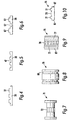
- Figs 7 to 10 show the elements of a proposal not according to the invention in which the respective parts of the belt for driving and centring are arranged side-by-side instead of end-to-end.
- a drive pulley 71 has toothing 72 restricted to a central region thereof.
- the idler pulley 78 has circumferential grooves 88 located in the edge regions thereof.
- the drive belt 75 is conveniently of uniform construction throughout its length and comprises a toothed central region 76, for engagement with toothing 72, and ribs 77 at its edge regions 87 for engagement with grooves 88 to restrict lateral movement of the belt.
- the grooves 88 and ribs 77 may be provided in any convenient number and may be interchanged as desired.
- a single toothed region 76 adjacent one edge of the belt 75 may extend parallel to a single ribbed and/or grooved region 87 adjacent the other edge of the belt.
- two toothed regions 76 adjacent the edges may be separated by a single grooved/ribbed region. Again the toothing may be replaced by another suitable intergaging or frictional arrangement.
Landscapes
- Engineering & Computer Science (AREA)
- General Engineering & Computer Science (AREA)
- Mechanical Engineering (AREA)
- Character Spaces And Line Spaces In Printers (AREA)
- Handling Of Sheets (AREA)
- Devices For Conveying Motion By Means Of Endless Flexible Members (AREA)
Description
- The present invention relates to a belt drive arrangement, in particular of the type used in printers.
- In prior art belt drives, both a motor drive pulley and the internal surface of a looped belt have their surfaces configured, e.g. by toothing, such that they ensure a secure mutual grip. In printers, such belts are used to achieve reliable drive and accurate positioning for the scan axis. The motor drive pulley is located at one end of the scan axis. At the other end of the scan axis there is located an undriven idler pulley that simply acts as a tensioner; conventionally, the idler pulley has a flat surface since no grip on the belt is required.
- Belt drives of the above type are disclosed in US Patents 4, 761, 154 and U.S. 5, 276, 970.
- A problem with such prior art belt drives is that, unless the drive and idler pulleys are relatively close together, movement of the belt in a direction transverse of the scan axis arises at the idler pulley. As a result the belt rubs against the flanges of the idler pulley producing undesired wear of both the belt and the pulley, which eventually leads to unsatisfactory operation of the system.
- The present invention seeks to overcome or reduce the above problem.
- Moreover, U.S. patent 4,634,409 discloses a belt drive arrangement comprising a drive pulley, an idler pulley and an endless drive belt passing around both pulleys the idler pulley having a circumferential flange which engages the belt between rows of teeth thereon which are driven by lugs on the drive pulley. The disclosure of this document corresponds generally to the introductory parts of claims 1 and 6.
- U.S. patent 4,044,882 discloses a printer carriage with a reciprocating drive belt which is toothed only on the portion which engages the drive pulley and is flat over the remaining portion.
- According to a first aspect of the invention, there is provided a belt drive arrangement according to claim 1.
- An advantage of the above described arrangement is that transverse movement of the belt in the region of the idler pulley is avoided. This reduces wear of the belt. In addition operation of the belt drive involves less vibrations and this is quieter.
- The arrangement is a reciprocating belt drive arrangement in which the belt is arranged to be driven backwards and forwards by the drive pulley. A single first part extends along one portion of the length of the belt and a single second part extends along another portion of the length of the belt. Each portion preferably constitutes substantially half of the length of the belt.
- The or each first part of the belt is preferably toothed for engagement with toothing on the drive pulley.
- An additional advantage of the arrangement as claimed in claim 1 is that, in view of the engagement between the grooves and the ribs, the idler pulley no longer requires flanges to retain the belt thereon.
- According to a second aspect of the present invention there is provided an endless drive belt as claimed in claim 6.
- Preferred embodiments of the present invention will now be described, by way of example only, with reference to the accompanying drawings, of which:
- Fig. 1 shows a prior art belt drive arrangement;
- Fig. 2 shows a belt drive arrangement in accordance with a first embodiment of the present invention;
- Fig. 3 and 4 are enlarged sectional views of part of the belt of the arrangement of Fig. 2;
- Figs 5 and 6 are views similar to Fig 4 of modified belts;
- Figs 7 and 8 show the drive and idler pulleys respectively of a belt drive arrangement in accordance with a proposal not according to the present invention; and
- Figs 9 and 10 are plan and sectional views of the belt used in the proposal.
-
- Referring to the drawings, Fig 1 shows a known
belt drive arrangement 10 as employed in printers to drive printhead carriages in the scan axis direction.Arrangement 10 comprises a motor drive pulley or roller 11 with atoothed drive surface 12, which drivingly engages theinternal surface 16 of abelt 15. (The return length of the belt nearer to the observer in Fig. 1, has been omitted for reasons of clarity).Internal surface 16 has transversely-extending teeth having a constant profile along the entire length of the belt. - In use, pulley 11 is driven alternately in one sense and then the other to drive the belt in a reciprocating manner as indicated by arrow A, so as to move the printhead back and forth across the print medium in the direction of the scan axis. Since no power transmission occurs at the
idler pulley 18, its surface is, in practice, substantially flat. Accordingly, the belt undergoes unwanted up and down movement, as indicated by arrow B, and this causes wear ofbelt 15 andpulley 18. - Referring now to Fig. 2, there is shown a
belt drive arrangement 20 in accordance with a first embodiment of the present invention. Again, motor drive pulley 11 has atoothed surface 12. However,idler pulley 28 has threecircumferential grooves 27. In addition, the length ofdrive belt 25 is divided into two halves. Afirst half 26 is provided with teeth similar to those ofbelt 15 for engagement with pulley 11. However, thesecond half 36 is provided with threelongitudinal ribs 37 at a spacing corresponding to the spacing betweengrooves 27. In use, asbelt 25 reciprocates as indicated by the arrow A, a part of thetoothed half 26 remains in contact with the drive pulley 11 and a part of the ribbedhalf 36 remains in contact with theidler pulley 28. Thus the belt is driven as in the prior art arrangement, but at the same time,ribs 37 remain in engagement withrespective grooves 27 so that there is no up and down movement, i.e in a direction transverse to the length of the belt. - A
typical belt 25 is made of black polyurethane with a Shore hardness of 80 to 83 and reinforced with fibres, in particular kevlar reinforcement cords placed inside the polyurethane. For use in a printer, the belt has a total length of approximately 3005 mm and its first half has 737 lateral teeth with a spacing of 2.03 mm. As shown in Fig 3, the opposite side ofbelt 25 is provided along its entire length withrecesses 39 at a spacing of 6.10 mm corresponding to every third tooth.Recesses 39 are present to locate and support the kevlar cords during manufacture, in particular when inside a mould before and during injection of the polyurethane, but they also facilitate flexing ofbelt 25 around thepulleys 28 and 11. Fig 3 shows the region of thebelt 25 at one of thejunctions 40 of the twohalves junctions 40 reach either of thepulleys 28, 11. - Fig 4 shows a sectional view of the ribbed
half 36 ofbelt 25. The transition between the teeth (on first half 26) and the ribs 37 (on second half 36) affects only the polyurethane, and the belt does not lose continuity at this point. - Various modifications can be made to the above described arrangement. For example, the
idler pulley 28 may have ribs, in whichcase grooves 47 are provided along the surface ofpart 36 of the belt as shown in Fig 5. Whichever arrangement is adopted, the number of ribs and associated grooves may be one, two or more than three. Theidler pulley 28 and thepart 36 may each be provided with a rib/groove combination; for example, ifpulley 28 has a central rib and two side grooves, thepart 36 has acentral groove 57 and twoside ribs 67 as shown in Fig 6. - Moreover, for printheads with reduced limits of travel, the
toothed part 26 and the ribbed/grooved part 36 may extend over less than half of the total length of the belt. Instead of being continuous at both ends,parts - The
toothing 12 of the drive pulley 11 and the toothing onpart 26 of the belt may be replaced by any other intergaging arrangements or by frictional surfaces provided that a drive effect is produced in the longtiudinal direction of the belt. For example, studs on the pulley could engage in recesses in the belt, or vice versa. Any suitable material may be used for thebelt 25, andrecesses 39 may be omitted. - The pulley axes may be arranged horizontally rather than vertically.
- Figs 7 to 10 show the elements of a proposal not according to the invention in which the respective parts of the belt for driving and centring are arranged side-by-side instead of end-to-end. A
drive pulley 71 has toothing 72 restricted to a central region thereof. Theidler pulley 78 hascircumferential grooves 88 located in the edge regions thereof. In this proposal thedrive belt 75 is conveniently of uniform construction throughout its length and comprises a toothedcentral region 76, for engagement withtoothing 72, andribs 77 at itsedge regions 87 for engagement withgrooves 88 to restrict lateral movement of the belt. - An advantage of this arrangement is that reciprocation of the belt is not restricted to part of its length. Indeed, this proposal is not limited to reciprocating arrangements at all.
- Various modifications may be made to the above-described proposal. For example, as with the first embodiment, the
grooves 88 andribs 77 may be provided in any convenient number and may be interchanged as desired. A singletoothed region 76 adjacent one edge of thebelt 75 may extend parallel to a single ribbed and/or groovedregion 87 adjacent the other edge of the belt. Alternatively, twotoothed regions 76 adjacent the edges may be separated by a single grooved/ribbed region. Again the toothing may be replaced by another suitable intergaging or frictional arrangement.
Claims (9)
- A belt drive arrangement (20) comprising a drive pulley (11), an idler pulley (28) and a drive belt (25) which is looped around both pulleys and which is arranged to be driven by the drive pulley, the idler pulley (28) having one or more circumferential grooves and/or ribs (27) and the face of the belt facing the pulleys being divided into first and second parts (26, 36), the or each first part (26) having a surface configured for driving engagement with the drive pulley (11) and the or each second part (36) having one or more longitudinally-extending ribs and/or grooves (37) respectively for engagement with the idler pulley, characterised in that the belt (25) is arranged to be driven in a reciprocating manner by the drive pulley (11) and in that a said first part (26) of the belt extends along a portion of the length of the belt and a said second part (36) of the belt extends along another portion of the length of the belt.
- A belt drive arrangement (20) according to claim 1, wherein the first and second parts (26, 36) each extend along substantially half of the length of the belt (25).
- A belt drive arrangement (20) according to claim 1 or 2, wherein the drive pulley (11) has toothing (12) and the surface of the or each first part (26) is also toothed.
- A belt drive arrangement (20) according to any preceding claim arranged to drive a driven member between limit positions which correspond to the drive pulley (11) engaging relatively-spaced locations on the belt (25) which are both within said first part (26).
- A printer comprising a belt drive arrangement (20) according to claim 4, wherein the driven member is a printhead carriage.
- An endless drive belt (25) in the form of a loop with opposed outer and inner surfaces, the inner surface being divided into first and second parts (26, 36) with the first part (26) having means for producing a longitudinal drive effect and the second part (36) having one or more longitudinally-extending ribs or grooves (27), characterised in that said first and second parts (26, 36) are located relatively longitudinally of each other.
- A belt (25) according to claim 6 wherein the means for producing a longitudinal drive effect are transverse teeth.
- A belt (25) according to claim 6 or 7, wherein the first and second parts (26, 36) have substantially the same length.
- A belt according to claim 8, wherein each of the first and second parts (26, 36) extends over substantially half the length of the belt.
Priority Applications (4)
| Application Number | Priority Date | Filing Date | Title |
|---|---|---|---|
| ES98113230T ES2182190T3 (en) | 1998-07-16 | 1998-07-16 | BELT IMPULSION DEVICE. |
| DE69809208T DE69809208T2 (en) | 1998-07-16 | 1998-07-16 | belt transmission |
| EP98113230A EP0972645B1 (en) | 1998-07-16 | 1998-07-16 | Belt drive arrangement |
| US09/352,739 US6123473A (en) | 1998-07-16 | 1999-07-14 | Belt drive arrangement for a printhead carriage |
Applications Claiming Priority (1)
| Application Number | Priority Date | Filing Date | Title |
|---|---|---|---|
| EP98113230A EP0972645B1 (en) | 1998-07-16 | 1998-07-16 | Belt drive arrangement |
Publications (2)
| Publication Number | Publication Date |
|---|---|
| EP0972645A1 EP0972645A1 (en) | 2000-01-19 |
| EP0972645B1 true EP0972645B1 (en) | 2002-11-06 |
Family
ID=8232282
Family Applications (1)
| Application Number | Title | Priority Date | Filing Date |
|---|---|---|---|
| EP98113230A Expired - Lifetime EP0972645B1 (en) | 1998-07-16 | 1998-07-16 | Belt drive arrangement |
Country Status (4)
| Country | Link |
|---|---|
| US (1) | US6123473A (en) |
| EP (1) | EP0972645B1 (en) |
| DE (1) | DE69809208T2 (en) |
| ES (1) | ES2182190T3 (en) |
Families Citing this family (14)
| Publication number | Priority date | Publication date | Assignee | Title |
|---|---|---|---|---|
| JP3386724B2 (en) * | 1998-09-08 | 2003-03-17 | 株式会社椿本チエイン | Synchronous belt with positioning confirmation function |
| US6583803B2 (en) | 2001-01-29 | 2003-06-24 | Zih Corporation | Thermal printer with sacrificial member |
| US6919115B2 (en) * | 2002-01-08 | 2005-07-19 | Cool Options, Inc. | Thermally conductive drive belt |
| US7134736B2 (en) * | 2004-01-08 | 2006-11-14 | Fuji Xerox Co., Ltd. | Printer with printhead fully traveling around drive belt loop |
| US20050159262A1 (en) * | 2004-01-21 | 2005-07-21 | Brecoflex Co., L.L.C. | Timing belt with wave glide surface |
| EP1653119B1 (en) * | 2004-10-28 | 2008-02-27 | Dayco Europe S.r.l. con Unico Socio | Pulley and belt drive assembly for driving accessory parts of an internal combustion engine |
| US7744732B2 (en) * | 2005-04-06 | 2010-06-29 | Leviton Manufacturing Company, Inc. | Continuous plating system and method with mask registration |
| US7655117B2 (en) * | 2005-04-06 | 2010-02-02 | Leviton Manufacturing Co., Inc. | Continuous plating system and method with mask registration |
| JP2007182910A (en) * | 2005-12-29 | 2007-07-19 | Brother Ind Ltd | Pulley holder |
| JP2007181934A (en) * | 2005-12-29 | 2007-07-19 | Brother Ind Ltd | Pulley holder support structure, pulley holder |
| US8182655B2 (en) * | 2007-09-05 | 2012-05-22 | Leviton Manufacturing Co., Inc. | Plating systems and methods |
| JP6349806B2 (en) * | 2014-03-14 | 2018-07-04 | セイコーエプソン株式会社 | Liquid ejecting apparatus and driving method of liquid ejecting apparatus |
| DE102015007779A1 (en) * | 2015-06-19 | 2016-12-22 | Webasto SE | Method for producing a plastic drive cable |
| CN108137235B (en) * | 2015-10-08 | 2020-03-10 | 莱特拉姆有限责任公司 | Conveyor belt with longitudinal rails |
Family Cites Families (19)
| Publication number | Priority date | Publication date | Assignee | Title |
|---|---|---|---|---|
| US2770977A (en) * | 1953-11-27 | 1956-11-20 | Continental Gummi Werke Ag | Belt transmissions |
| DE2445081C3 (en) * | 1974-09-20 | 1985-12-05 | Siemens AG, 1000 Berlin und 8000 München | Arrangement for controlling the movement of a printer carriage for printing units, in particular for teleprinters and typewriters |
| US4026162A (en) * | 1975-07-23 | 1977-05-31 | Berg Winfred M | Toothed transmission belt |
| IT1138320B (en) * | 1981-05-07 | 1986-09-17 | Honeywell Inf Systems | ADJUSTABLE DIAMETER TRANSMISSION PULLEY |
| JPS58203257A (en) * | 1982-05-24 | 1983-11-26 | Honda Motor Co Ltd | belt drive device |
| JPS58214053A (en) * | 1982-06-08 | 1983-12-13 | Ito Kogyo Kk | Toothed belt driving gear |
| US4715737A (en) * | 1982-07-07 | 1987-12-29 | Alps Electric Co., Ltd. | Printer with paper feed roller disengagement mechanism |
| US4571224A (en) * | 1982-07-27 | 1986-02-18 | Unitta Co., Ltd. | Belt drive system |
| US4634409A (en) * | 1985-03-05 | 1987-01-06 | The Goodyear Tire & Rubber Company | Idler pulley |
| DE3537464A1 (en) * | 1985-10-22 | 1987-04-23 | Philips Patentverwaltung | Drive for moving a print head of a printer |
| GB2183771B (en) * | 1985-11-30 | 1990-05-16 | Burroughs Corp | Printhead transport apparatus |
| JPS63173676A (en) * | 1987-01-13 | 1988-07-18 | Canon Inc | Carriage transport device |
| US4761154A (en) | 1987-05-28 | 1988-08-02 | Hewlett-Packard Company | Belt tensioner |
| US5044797A (en) * | 1988-04-01 | 1991-09-03 | Ncr Corporation | Device for connecting a timing belt to a printhead carriage |
| DE3909949C2 (en) * | 1989-03-25 | 1993-12-23 | Breco Kunststoff | Belt drive consisting of a toothed belt and a toothed pulley |
| FR2655752B1 (en) * | 1989-12-08 | 1992-12-31 | Alcatel Satmam | POSTAGE MACHINE WITH INTEGRATED CONVEYOR. |
| US5276970A (en) | 1991-10-30 | 1994-01-11 | Hewlett-Packard Company | Codestrip in a large-format image-related device |
| JPH0681913A (en) * | 1992-09-03 | 1994-03-22 | Ricoh Co Ltd | Driving transmission mechanism |
| CH687272A5 (en) * | 1993-03-02 | 1996-10-31 | Rene Steinmetz | Drive mechanism with toothed belt |
-
1998
- 1998-07-16 EP EP98113230A patent/EP0972645B1/en not_active Expired - Lifetime
- 1998-07-16 DE DE69809208T patent/DE69809208T2/en not_active Expired - Lifetime
- 1998-07-16 ES ES98113230T patent/ES2182190T3/en not_active Expired - Lifetime
-
1999
- 1999-07-14 US US09/352,739 patent/US6123473A/en not_active Expired - Lifetime
Also Published As
| Publication number | Publication date |
|---|---|
| EP0972645A1 (en) | 2000-01-19 |
| ES2182190T3 (en) | 2003-03-01 |
| DE69809208D1 (en) | 2002-12-12 |
| DE69809208T2 (en) | 2003-07-17 |
| US6123473A (en) | 2000-09-26 |
Similar Documents
| Publication | Publication Date | Title |
|---|---|---|
| US6123473A (en) | Belt drive arrangement for a printhead carriage | |
| US3643518A (en) | Belt and belt drive assembly | |
| US7810637B2 (en) | Positively driven, tracking flat belt and conveyor | |
| US4571224A (en) | Belt drive system | |
| US4725221A (en) | Improved machine for continuously producing an element of a separable fastener | |
| US6698850B2 (en) | Elastic crawler traveling apparatus and sprocket for crawler belt used in the same | |
| US7329196B2 (en) | Guide for transmission device | |
| US3948110A (en) | Endless cleated track | |
| US20090042683A1 (en) | Silent chain | |
| US7393487B2 (en) | Method of molding synthetic resin guide for transmission device | |
| US6440022B1 (en) | Double-meshing type silent chain and sprocket for meshing with the chain along outer circumference thereof | |
| US20130053197A1 (en) | Transmission guide | |
| CA2012942C (en) | Belt drive comprising a toothed belt and a toothed pulley | |
| CA1306622C (en) | Toothed belt drive | |
| EP1366310A2 (en) | Endless power transmission belt | |
| US7008341B2 (en) | Reduced noise multi-ribbed power transmission belt | |
| US5868639A (en) | Positive engagement drive | |
| EP1528288B1 (en) | Guide for a transmission device | |
| US4614510A (en) | Polyurethane toothed belt structure | |
| US6866603B2 (en) | Counter-rotational drive belt system and method | |
| JP2002255066A (en) | Elastic crawler | |
| JP2652982B2 (en) | Timing belt for power transmission of serial printer | |
| US20210381581A1 (en) | Bicycle chain | |
| JP2540033Y2 (en) | Power transmission belt | |
| JP2937491B2 (en) | V belt for high load transmission |
Legal Events
| Date | Code | Title | Description |
|---|---|---|---|
| PUAI | Public reference made under article 153(3) epc to a published international application that has entered the european phase |
Free format text: ORIGINAL CODE: 0009012 |
|
| AK | Designated contracting states |
Kind code of ref document: A1 Designated state(s): DE ES FR GB |
|
| AX | Request for extension of the european patent |
Free format text: AL;LT;LV;MK;RO;SI |
|
| 17P | Request for examination filed |
Effective date: 20000216 |
|
| AKX | Designation fees paid |
Free format text: DE ES FR GB |
|
| 17Q | First examination report despatched |
Effective date: 20001107 |
|
| RAP1 | Party data changed (applicant data changed or rights of an application transferred) |
Owner name: HEWLETT-PACKARD COMPANY, A DELAWARE CORPORATION |
|
| GRAG | Despatch of communication of intention to grant |
Free format text: ORIGINAL CODE: EPIDOS AGRA |
|
| GRAG | Despatch of communication of intention to grant |
Free format text: ORIGINAL CODE: EPIDOS AGRA |
|
| GRAH | Despatch of communication of intention to grant a patent |
Free format text: ORIGINAL CODE: EPIDOS IGRA |
|
| GRAH | Despatch of communication of intention to grant a patent |
Free format text: ORIGINAL CODE: EPIDOS IGRA |
|
| GRAA | (expected) grant |
Free format text: ORIGINAL CODE: 0009210 |
|
| AK | Designated contracting states |
Kind code of ref document: B1 Designated state(s): DE ES FR GB |
|
| REG | Reference to a national code |
Ref country code: GB Ref legal event code: FG4D |
|
| REF | Corresponds to: |
Ref document number: 69809208 Country of ref document: DE Date of ref document: 20021212 |
|
| REG | Reference to a national code |
Ref country code: ES Ref legal event code: FG2A Ref document number: 2182190 Country of ref document: ES Kind code of ref document: T3 |
|
| ET | Fr: translation filed | ||
| PLBE | No opposition filed within time limit |
Free format text: ORIGINAL CODE: 0009261 |
|
| STAA | Information on the status of an ep patent application or granted ep patent |
Free format text: STATUS: NO OPPOSITION FILED WITHIN TIME LIMIT |
|
| 26N | No opposition filed |
Effective date: 20030807 |
|
| PGFP | Annual fee paid to national office [announced via postgrant information from national office to epo] |
Ref country code: ES Payment date: 20070726 Year of fee payment: 10 |
|
| PGFP | Annual fee paid to national office [announced via postgrant information from national office to epo] |
Ref country code: FR Payment date: 20070717 Year of fee payment: 10 |
|
| REG | Reference to a national code |
Ref country code: FR Ref legal event code: ST Effective date: 20090331 |
|
| PG25 | Lapsed in a contracting state [announced via postgrant information from national office to epo] |
Ref country code: FR Free format text: LAPSE BECAUSE OF NON-PAYMENT OF DUE FEES Effective date: 20080731 |
|
| REG | Reference to a national code |
Ref country code: ES Ref legal event code: FD2A Effective date: 20080717 |
|
| PG25 | Lapsed in a contracting state [announced via postgrant information from national office to epo] |
Ref country code: ES Free format text: LAPSE BECAUSE OF NON-PAYMENT OF DUE FEES Effective date: 20080717 |
|
| REG | Reference to a national code |
Ref country code: GB Ref legal event code: 732E Free format text: REGISTERED BETWEEN 20120329 AND 20120404 |
|
| PGFP | Annual fee paid to national office [announced via postgrant information from national office to epo] |
Ref country code: GB Payment date: 20130626 Year of fee payment: 16 |
|
| PGFP | Annual fee paid to national office [announced via postgrant information from national office to epo] |
Ref country code: DE Payment date: 20130621 Year of fee payment: 16 |
|
| REG | Reference to a national code |
Ref country code: DE Ref legal event code: R119 Ref document number: 69809208 Country of ref document: DE |
|
| GBPC | Gb: european patent ceased through non-payment of renewal fee |
Effective date: 20140716 |
|
| PG25 | Lapsed in a contracting state [announced via postgrant information from national office to epo] |
Ref country code: DE Free format text: LAPSE BECAUSE OF NON-PAYMENT OF DUE FEES Effective date: 20150203 |
|
| REG | Reference to a national code |
Ref country code: DE Ref legal event code: R119 Ref document number: 69809208 Country of ref document: DE Effective date: 20150203 |
|
| PG25 | Lapsed in a contracting state [announced via postgrant information from national office to epo] |
Ref country code: GB Free format text: LAPSE BECAUSE OF NON-PAYMENT OF DUE FEES Effective date: 20140716 |