EP0971278A1 - Solenoid valve with pressure transducer - Google Patents
Solenoid valve with pressure transducer Download PDFInfo
- Publication number
- EP0971278A1 EP0971278A1 EP99304114A EP99304114A EP0971278A1 EP 0971278 A1 EP0971278 A1 EP 0971278A1 EP 99304114 A EP99304114 A EP 99304114A EP 99304114 A EP99304114 A EP 99304114A EP 0971278 A1 EP0971278 A1 EP 0971278A1
- Authority
- EP
- European Patent Office
- Prior art keywords
- pressure
- solenoid
- sleeve
- fluid
- sensing element
- Prior art date
- Legal status (The legal status is an assumption and is not a legal conclusion. Google has not performed a legal analysis and makes no representation as to the accuracy of the status listed.)
- Granted
Links
Images


Classifications
-
- F—MECHANICAL ENGINEERING; LIGHTING; HEATING; WEAPONS; BLASTING
- F04—POSITIVE - DISPLACEMENT MACHINES FOR LIQUIDS; PUMPS FOR LIQUIDS OR ELASTIC FLUIDS
- F04B—POSITIVE-DISPLACEMENT MACHINES FOR LIQUIDS; PUMPS
- F04B27/00—Multi-cylinder pumps specially adapted for elastic fluids and characterised by number or arrangement of cylinders
- F04B27/08—Multi-cylinder pumps specially adapted for elastic fluids and characterised by number or arrangement of cylinders having cylinders coaxial with, or parallel or inclined to, main shaft axis
- F04B27/14—Control
- F04B27/16—Control of pumps with stationary cylinders
- F04B27/18—Control of pumps with stationary cylinders by varying the relative positions of a swash plate and a cylinder block
- F04B27/1804—Controlled by crankcase pressure
-
- G—PHYSICS
- G05—CONTROLLING; REGULATING
- G05D—SYSTEMS FOR CONTROLLING OR REGULATING NON-ELECTRIC VARIABLES
- G05D16/00—Control of fluid pressure
- G05D16/20—Control of fluid pressure characterised by the use of electric means
- G05D16/2006—Control of fluid pressure characterised by the use of electric means with direct action of electric energy on controlling means
- G05D16/2013—Control of fluid pressure characterised by the use of electric means with direct action of electric energy on controlling means using throttling means as controlling means
- G05D16/2024—Control of fluid pressure characterised by the use of electric means with direct action of electric energy on controlling means using throttling means as controlling means the throttling means being a multiple-way valve
-
- Y—GENERAL TAGGING OF NEW TECHNOLOGICAL DEVELOPMENTS; GENERAL TAGGING OF CROSS-SECTIONAL TECHNOLOGIES SPANNING OVER SEVERAL SECTIONS OF THE IPC; TECHNICAL SUBJECTS COVERED BY FORMER USPC CROSS-REFERENCE ART COLLECTIONS [XRACs] AND DIGESTS
- Y10—TECHNICAL SUBJECTS COVERED BY FORMER USPC
- Y10T—TECHNICAL SUBJECTS COVERED BY FORMER US CLASSIFICATION
- Y10T137/00—Fluid handling
- Y10T137/7722—Line condition change responsive valves
- Y10T137/7758—Pilot or servo controlled
- Y10T137/7761—Electrically actuated valve
-
- Y—GENERAL TAGGING OF NEW TECHNOLOGICAL DEVELOPMENTS; GENERAL TAGGING OF CROSS-SECTIONAL TECHNOLOGIES SPANNING OVER SEVERAL SECTIONS OF THE IPC; TECHNICAL SUBJECTS COVERED BY FORMER USPC CROSS-REFERENCE ART COLLECTIONS [XRACs] AND DIGESTS
- Y10—TECHNICAL SUBJECTS COVERED BY FORMER USPC
- Y10T—TECHNICAL SUBJECTS COVERED BY FORMER US CLASSIFICATION
- Y10T137/00—Fluid handling
- Y10T137/8158—With indicator, register, recorder, alarm or inspection means
- Y10T137/8326—Fluid pressure responsive indicator, recorder or alarm
Definitions
- a discrete pressure sensor can be added to an existing solenoid valve body or housing.
- the overall packaging of the combination device is quite large and does not integrate them into one unit. Also, combining two or more devices does not eliminate leak paths in the system.
- the elements-used for pressure sensing are included within the solenoid device. These elements include sponge 530, wire bond 532, glass bond 533, silicon die 529, and flex circuit assembly 531. Silicon die 529 (the sensing element) has an embedded Wheatstone bridge although other resistive elements may be used. A suitable silicon die is available from Sensym of Milpitas, California, or Motorola of Schaumberg, Illinois.
- the combined device in Figure 3a includes five terminals 512 having a common connection point formed by receptable 540 in connector body 515.
- two terminals connect to the solenoid valve--one to apply voltage to the coil 508 and one connected to ground, and three terminals connect to the pressure sensing technology--one to supply an input voltage to the flex circuit 531, one connected to ground and one providing an output voltage from the flex circuit.
- the deep-drawn manufacturing process produces a solenoid sleeve with a closed end able to flex under pressure, similar to a diaphragm.
- the deep-drawn manufacturing process also provides a more controlled and uniform strain throughout the solenoid sleeve.
- a machined sleeve may also be used. It is also desirable to use a sleeve material which has a CTE approximately equal to the value of the CTE of the silicon. The greater the difference in CTE, the greater the expansion and strain on the bonding agent used to connect the two materials.
Abstract
Description
- The present invention relates generally to pneumatic and hydraulic control systems and more particularly to systems requiring both a solenoid valve and a pressure sensor or transducer.
- Solenoid valves are used to control a flow of fluid (e.g., air, liquid or gas) within a system such as an air conditioning, hydraulic brake, or fuel system. A solenoid valve opens and closes flow passages by energizing a coil to produce a magnetic field which in turn, moves an internal armature.
- A pressure sensor or transducer is used to monitor fluid pressure within a system, such as a pneumatic or hydraulic system. As used herein, a pressure transducer includes both a pressure transducer and a pressure sensor. Generally, the measured pressure information is provided to an electrical control unit (ECU) located externally to a solenoid valve and which activates or deactivates (opens or closes) the solenoid valve based on the pressure information. There are several types of technology employed for pressure sensors and transducers which include, but are not limited to, ceramic, resistive, linear variable differential transformer (LVDT), piezoresistive, and piezoelectric. One common form of sensing pressure in automotive applications utilizes capacitive type sensors; however, these sensors require large volumes of space to house the sensing element and electronics.
- In an effort to improve efficiencies, reduce costs, and miniaturize package size, system designers often try to eliminate components while still maintaining the same or an improved level of performance. In conventional systems, a discrete pressure sensor can be added to an existing solenoid valve body or housing. However, in such a system, the overall packaging of the combination device is quite large and does not integrate them into one unit. Also, combining two or more devices does not eliminate leak paths in the system.
- A solenoid valve and a pressure transducer can be used to monitor and control the same types of fluid pressure; combining these two discrete components into one device would add value to a system. What is needed is an integrated solenoid pressure transducer that will provide an efficient method of incorporating pressure-sensing technology within an original envelope (housing) of a solenoid valve, and preferably provide a common electrical connection point. In addition, the integrated solenoid pressure transducer should preferably be easy and inexpensive to manufacture based on structural simplicity and the use of inexpensive materials.
- The present invention is directed to an integrated solenoid pressure transducer for measuring and controlling pressure within a system. The solenoid pressure transducer includes a pressure sensor incorporated into a solenoid valve assembly; more specifically, common pressure chamber is used both to sense pressure of a fluid (e.g., air, liquid, or gas) and to control the flow of the same fluid.
- In one embodiment, pressure sensing is performed by a silicon die having an embedded resistive element such as a Wheatstone bridge. The die is attached to a solenoid sleeve which forms the common pressure chamber. The silicon die may be attached to the closed end of the sleeve with a vitreous glass or other bonding agent.
- In certain preferred embodiments, the sleeve is made of a non-magnetic material, such as Inconel 600/601 or Nickel 200/201, and is deep-drawn and fully annealed. Preferably, the sleeve has a coefficient of thermal expansion of 7.4 x 10⁻⁶ in/in/°F or less for compatability with the silicon die.
- These and other features of the invention will be more specifically understood from the following detailed description and drawings.
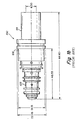
- Figure 1a is a cross sectional view of a prior art discrete solenoid valve;
- Figure 1b is a side view of the housing, with dimensions, of the solenoid valve of Figure 1a;
- Figure 2a is a cross sectional view of a prior art discrete pressure sensor;
- Figure 2b is a side view of the housing, with dimensions, of the pressure sensor of Figure 2a;
- Figure 2c is an end view of the housing, with dimensions, of the pressure sensor of Figure 2a;
- Figure 2d is an exploded parts view of the pressure sensor of Figure 2a;
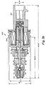
- Figure 3a is a cross sectional view of an integrated solenoid pressure transducer according to one embodiment of the present invention;
- Figure 3b is the same as Figure 3a with dimensions shown;
- Figure 4 is a schematic diagram of a closed end of a solenoid sleeve with an attached pressure sensing device according to one embodiment of the invention; and
- Figure 5 is a schematic diagram of an alternate embodiment of a closed end of a solenoid sleeve with an attached pressure sensing device.
-
- According to one aspect of the invention, an integrated solenoid pressure transducer is provided which includes a pressure sensing device attached to one end of a sleeve, the sleeve forming a pressure chamber common to both the solenoid valve and the pressure transducer. For ease of comparison, the prior art discrete pressure transducer and discrete solenoid valve will first be described.
- Figure 1a illustrates a prior
art solenoid valve 100 commonly used in automotive applications for controlling pressure of a fluid (e.g., air, liquid or gas). Anouter housing 106 shown in Figure la surrounds a solenoid assembly which includes anarmature 110,rod 109 and a coil assembly. The coil assembly includes acylindrical solenoid sleeve 111 having anopen end 119 and a closedend 120, animpact disc 114 inside the closed end of the sleeve, acoil 108 surrounding the sleeve, abobbin 113 outside the closed end of the sleeve, andelectrical terminals 112 within aconnector body 115 extending from the closed end of the sleeve. Thesolenoid sleeve 111 acts as a guide for thearmature 110 androd 109, which are press fit together.Rod 109 is connected to apin 104 which is surrounded by arubber impact seat 107 and disposed within the sleeve; the rod is axially movable in the cylindrical sleeve. The inside of thesolenoid sleeve 111 is exposed to a system pressure during certain operating modes and thus serves as a pressure chamber. The system fluid acts against aball 103, positioned upstream from the opcn end of the sleeve. Theball 103 is pushed to the right (downstream) by aspring 101, in order to close anorifice 121 inseat 102. - In operation, a system fluid enters into
seat 102 from a fluid source (not shown) and applies pressure toball 103. Meanwhile,coil 108 has been activated by a voltage applied toterminals 112, andcoil 108 creates a magnetic force which is applied torod 109 byarmature 110. The left-directed axially applied magnetic force causesrod 109 to push pin 104 (to the left) which in turn, pushes ball 103 (to the left). This movement breaks the seal betweenball 103 andseat 102 and opens theorifice 121. The fluid then enters into thevalve body 105; it travels aroundpin 104, throughimpact seat 107, intohousing 106 and continues aroundrod 109 insleeve 111 and through acentral hole 122 in theimpact disc 114; to the closedend 120 of thesolenoid sleeve 111. When the voltage is reduced or removed fromcoil 108, the left-directed force is reduced or removed fromrod 109 and the rod moves back to the right; as a result,spring 101 pushesball 103 insideseat 102 and seals off theorifice 121 invalve body 105, thereby cutting off the flow of fluid to and reducing the pressure insidesolenoid sleeve 111. - Returning to the operational mode wherein pressure is applied (by entry of the system fluid) to the pressure chamber, i.e., the inside of the
sleeve 111, the closedend 120 of the sleeve flexes due to the pressure and thus acts like a diaphragm. An appropriate thickness for the closedend 120 of thesleeve 111 is selected to respond to the system pressures at issue. For best performance of the valve, the sleeve material should be non-magnetic. A sleeve constructed from a magnetic material causes the magnetic flux produced by theenergized coil 108 to by-pass thearmature 110 and thus reduces any resultant force applied byarmature 110 torod 109. - Figure 1b is an outer view of the overall valve housing with dimensions; it will be discussed below in regard to the reduction in size of the combined solenoid pressure sensor of this invention.
- Figures 2a-2d illustrate one example of a prior art
piezoresistive pressure sensor 300 commonly used in automotive applications. Figure 2d is an exploded parts view of the pressure sensor of Figure 2a. - The pressure sensor of Figure 2a includes a set of
electrical terminals 316 extending from areceptacle 340 at one end of aconnector assembly 327. The other end of connector assembly fits within the right end ofhousing 320 and is held in place bygasket 317;housing 320 includes aright hand inlet 341 for the system fluid (to be measured) and encloses the sensing element. The inlet comprises the open end of an elongatedmetal pressure tube 323; which forms a pressure chamber. The opposite end oftube 323 is closed and forms amovable diaphragm 322 responsive to changes of pressure intube 323. A silicondie sensing element 318 is attached byglass bond 337 to the other side of the diaphragm for measuring the pressure of the fluid intube 323. Weld 328 and internal o-ring 324 holds the pressure tube in position inhousing 320. External o-ring 321 enables thehousing 320 to be attached to a system fluid source, whereby the system fluid entersinlet 341 ofpressure tube 323. - More specifically, the sensor includes a
flex circuit assembly 326 connected tosilicon die 318 bywire bonds 336; theflex circuit 326 is attached toelectrical connectors 316. Aprotective cap 319 surrounds thedie 318 and asponge 325 surrounds thecap 319 for further protection and vibration and shock dampening. - In operation, system fluid enters through the
open end 341 ofpressure tube 323 and causesdiaphragm 322 at the opposite end to flex. This flexing produces a strain on the opposite (rearside) ofdiaphragm 322. Silicon die 318 is attached to the rearside ofdiaphragm 322 with a bonding agent such asvitreous glass 337. Silicon die 318 includes an embedded resistive element for measuring strain, namely a Wheatstone bridge. The resistance in the Wheatstone bridge changes proportionally with the change in the strain in the silicon die 318 to produce an output voltage when a constant current is applied. The current and voltage are applied to the bridge byterminals 316. - The output voltage from the bridge is proportional to the strain in the
die 318 which, in turn, is proportional to the pressure insidepressure tube 323. The output voltage is defined by Ohm's Law: V=IR, i.e., the voltage is proportional to the current multiplied by the resistance. The current (I) through silicon die 318 is constant, thus the voltage (V) is directly proportional to the resistance (R) of the bridge. - The output voltage signal is compensated for temperature and linearity variations and amplified by the
flex circuit assembly 326, the assembly includes surface-mounted electrical components. The output voltage signal is carried by one or more of theterminals 316 to an electrical control unit (ECU) located outside of the pressure sensor (not shown). - In order for the sensor to function properly within a wide range of temperatures (e.g., -50 to 150° C) the material of
pressure tube 323 should preferably have a low coefficient of thermal expansion (CTE) (e.g., 7.4 x 10⁻⁶ in/in/°F or less). This low CTE is used because the silicon die 318 typically has such a low CTE. As the difference in the CTE between the two materials increases, thevitreous glass bond 337 may not withstand the strain and may crack or pop off of thepressure tube 323. - Vitreous glass is often used as a bonding agent because of its resistance to dimensional change in conditions of high temperature and/or stress. A change in dimensions of the bonding agent may cause the sensor to lose calibration. While vitreous glass is thus preferred, other bonding agents may be used.
- Figure 3a illustrates an integrated solenoid pressure transducer according to one embodiment of the invention. The integrated device incorporates a pressure sensing technology similar to that shown in Figure 2a into a solenoid valve similar to that shown in Figure 1a, in order to provide a single device for measuring and controlling pressure. A solenoid sleeve (e.g.,
sleeve 111 in Figure 1a) is similar in physical structure to a pressure tube (e.g.,tube 323 in Figure 2a) in a pressure sensor. In accordance with the present invention, by attaching a pressure sensing element to the closed end of the solenoid sleeve, the sensing element can measure the strain of the solenoid sleeve--similar to the measurement of strain in the diaphragm of the pressure sensor. This strain can be converted to a voltage signal which is proportional to the strain. The output voltage signal thus provides a voltage that is proportional to the system pressure and can be used to control the system pressure. - Thus, in the integrated sensor of Figure 3a, in addition to the parts discussed above in connection with Figure 1 (corresponding elements in Figure 3a have a 500 series reference number), the elements-used for pressure sensing are included within the solenoid device. These elements include sponge 530, wire bond 532,
glass bond 533, silicon die 529, andflex circuit assembly 531. Silicon die 529 (the sensing element) has an embedded Wheatstone bridge although other resistive elements may be used. A suitable silicon die is available from Sensym of Milpitas, California, or Motorola of Schaumberg, Illinois. - The combined device in Figure 3a includes five
terminals 512 having a common connection point formed byreceptable 540 inconnector body 515. In this embodiment, two terminals connect to the solenoid valve--one to apply voltage to thecoil 508 and one connected to ground, and three terminals connect to the pressure sensing technology--one to supply an input voltage to theflex circuit 531, one connected to ground and one providing an output voltage from the flex circuit. - In operation, system fluid enters
seat 502 viainlet 541 and applies a right directed pressure toball 503. Whencoil 508 is activated by voltage from theterminals 512, a left directed magnetic force is applied torod 509 byarmature 510.Rod 509 moves to the left and pushes onpin 504 which pushes onball 503. Depending on the balance of forces, this breaks the seal betweenball 503 andseat 502. This allows the system fluid to enter into thevalve body 505, travel aroundpin 504 and continue aroundrod 509 through thehole 544 in theimpact disc 514 at the closed end ofsleeve 511. Thediaphragm 522 on the closed end ofsleeve 511 is flexed, producing strain on the rear surface ofdiaphragm 522. In this embodiment, silicon die 529 is attached to diaphragm 522 withvitreous glass 533 on the rear side of the diaphragm (opposite the surface exposed to the system pressure). In another embodiment, a sensing element, such as silicon die 529, may be attached to any location onsolenoid sleeve 111 which allows thedie 529 or other sensing element to sense the strain onsleeve 111. Silicon die 529 is strained by the diaphragm and produces a voltage, which is proportional to the strain, which, in turn, is proportional to the pressure insidesleeve 511. Ohm's Law, V=IR, describes this voltage change. The current throughdie 529 is constant thus the output voltage (V) is directly proportional to the resistance (R) change of the Wheatstone bridge (due to the strain). The output voltage signal is compensated for temperature and linearity and is amplified by theflex circuit assembly 531;flex circuit 531 contains surface-mounted electrical components and integrated circuits. Abobbin 513 supports one end offlex circuit assembly 531. The opposite end of theflex circuit 531 is attached to theterminals 512. The signal fromflex circuit 531 is carried to an ECU via theterminals 512. Power is supplied to the circuit through one of theterminals 512. A sponge(s) 530 is placed between the lobe(s) of theflex circuit assembly 531 to protect the electrical components from vibration and shock. - When voltage is removed from
coil 508, the magnetic force is removed fromrod 509 and the rod moves back to the right.Spring 501 pushesball 503 to the right insideseat 502 and seals off the valve. The pressure is therefore removed fromdiaphragm 522; this reduces the strain die 529 and reduces the resistance in the embedded Wheatstone bridge. - In one embodiment, the pressure sensing technology is piezoresistive. The die, when strained, produces a millivolt output due to a resistance change of the Wheatstone bridge. The size of the die may be small (e.g., 0.020" square and .002" thick), which allows for extremely small device sizes.
- The use of ASICs and other state-of-the-art electronics allows the small pressure-sensing subassembly to be packaged inside the solenoid valve.
- As described above, the solenoid sleeve provides a surface for attaching the sensing element (e.g., a silicon die). In one embodiment, the sleeve material may be a non-magnetic metal alloy such as Inconel 600/601 or Nickel 200/201, available from Ulbrich Stainless Steels and Special Metals, Inc., although other materials may also be used. Both of these materials provide three desirable characteristics for the solenoid sleeve: (1) they are non-magnetic when fully annealed; (2) they have a CTE of 7.4 x 10⁻⁶ in/in/°F or less; and (3) they can be deep-drawn. The annealing process removes work hardening stresses from the sleeve material. The deep-drawn manufacturing process produces a solenoid sleeve with a closed end able to flex under pressure, similar to a diaphragm. The deep-drawn manufacturing process also provides a more controlled and uniform strain throughout the solenoid sleeve. A machined sleeve may also be used. It is also desirable to use a sleeve material which has a CTE approximately equal to the value of the CTE of the silicon. The greater the difference in CTE, the greater the expansion and strain on the bonding agent used to connect the two materials.
- Figure 4 is a schematic enlarged view of a closed end of the solenoid sleeve, according to one embodiment. Fluid pressure enters the
sleeve 606 and strains the closed end of the sleeve, causing it to act like a diaphragm. A silicon die 602 is attached to the rear side of the closed end of thesleeve 606 withvitreous glass 601.Vitreous glass 601 provides a rigid bond that allows the strain in the closed end of the sleeve to be transferred to thedie 602. This strain changes the resistance of the Wheatstone bridge that is embedded in the silicon die 602. This change in resistance produces a change in voltage proportional to the strain which is proportional to the fluid pressure. - In this embodiment, the Wheatstone bridge has four
wire bond pads 604.Gold wire bonds 603 are attached topads 604 which are connected electrically to theflex circuit subassembly 605. Theflex circuit subassembly 605 contains an ASIC and other electrical components to amplify and correct the signal for temperature changes and non-linearity. Theflex circuit 605 may be made of a Kapton substrate. - Figure 5 is a schematic enlarged view of another embodiment using a piezoresistive micro-machined silicon die to sense pressure in the solenoid valve. In this embodiment, the closed end of the
sleeve 807 has anorifice 810 that allows the fluid pressure to enter into the silicon die 804. The die is made of two silicon pieces. Atop piece 808 has a reduced thickness central portion which acts as the diaphragm and includes an embeddedWheatstone bridge 803. The top piece is attached at opposing edges to abottom die piece 809. The bottom die is attached to thesleeve 807 with abonding agent 805.Bonding agent 805 may be a "hard" die attachment, such as solder or glass, or a "soft" die attachment, such as a room temperature vulcanizing (RTV) silicone. The embeddedWheatstone bridge 803 is attached via awire bond 802 togold bonding pads 801 onflex circuit 806. The fluid pressure strains the silicon die which produces a voltage signal (in the Wheatstone bridge 803) that is proportional to the fluid pressure. This embodiment allows pressure sensing for very low-pressure applications. Because the sleeve does not act as a diaphragm, the sleeve need not have a low CTE (e.g., below 7.4 x 10⁻⁶ in/in/°F). - One advantage of the present invention can be seen by comparing the overall dimensions of a conventional solenoid valve (Figure 1b) and a conventional pressure sensor (Figure 2b) with the overall dimensions of the combined solenoid pressure transducer of the present invention as shown in Figure 3b. For example, a conventional solenoid valve may have an overall dimension of 88.90 mm x 22.95 mm (Figure 1b). A conventional pressure sensor device may, for example, have an overall dimension of 47.22 mm x 25.88 mm (Figure 2b). A prior art combined device required a housing which was essentially a combination of the housings of both discrete prior art devices. However, in the present invention, the features of both of these devices are included within the housing of a solenoid valve which in this embodiment is only slightly larger than the solenoid valve of Figure 1b. The overall dimensions of the combined solenoid pressure transducer according to an embodiment of the present invention may be, for example 98.90 mm x 22.95 mm (Figure 3b).
- Having now described certain embodiments of the invention, it will be apparent to those skilled in the art that the foregoing is merely illustrative and not limiting, having been presented by way of example only. Numerous modifications and other embodiments are within the scope of one of ordinary skill in the art and are contemplated as falling within the scope of the invention.
Claims (18)
- A solenoid pressure transducer for measuring and controlling pressure within a system comprising:a solenoid sleeve enclosing a pressure chamber, the pressure chamber being in communication with a source of the system pressure;a sensing element in contact with the pressure chamber for measuring the system pressure within the pressure chamber; andan actuator within the solenoid sleeve for controlling the system pressure in response to a pressure measured by the sensing element.
- The solenoid pressure transducer of claim 1, wherein the sensing element is a silicon die.
- The solenoid pressure transducer of claim 2, wherein the material of the solenoid sleeve has a coefficient of thermal expansion approximately equal to the coefficient of thermal expansion of the sensing element.
- The solenoid pressure transducer of claim 3, wherein the solenoid sleeve material has a coefficient of thermal expansion of 7.4 x 10⁻⁶ in/in/°F or less.
- The solenoid pressure transducer of claim 1, wherein the solenoid sleeve is constructed of a nonmagnetic material.
- The solenoid pressure transducer of claim 5, wherein the solenoid sleeve is made of a material comprising one of: Inconel 600/601 or Nickel 200/201.
- The solenoid pressure transducer of claim 6, wherein the solenoid sleeve is deep-drawn and annealed.
- The solenoid pressure transducer of claim 1, wherein the solenoid sleeve has a closed end and the sensing element is attached to the closed end.
- The solenoid pressure transducer of claim 1, wherein the solenoid sleeve includes an orifice and the sensing element is disposed adjacent the orifice in fluid communication with the pressure chamber.
- The solenoid pressure transducer of claim 2, wherein the sensing element includes an embedded Wheatstone bridge.
- The solenoid pressure transducer of claim 1, wherein the actuator includes an armature mounted within the solenoid sleeve.
- The solenoid pressure transducer of claim 1, wherein the transducer has a common set of electrical connectors for the actuator and sensing element.
- A solenoid pressure transducer for measuring pressure of a fluid comprising:a solenoid sleeve forming a pressure chamber, the sleeve having an opening in fluid communication with a source of the fluid and a portion movable in response to a pressure of the fluid in the pressure chamber; anda pressure sensing element responsive to a movement of the movable portion.
- A pressure controller for controlling pressure of a fluid, comprising:a solenoid sleeve having an opening in fluid communication with a source of the fluid and forming a pressure chamber;a sensing element positioned to respond to pressure within the pressure chamber;a valve, positioned between the source of the fluid and the pressure chamber, movable between an open position in which the pressure chamber is in fluid communication with the source of the fluid and a closed position in which the pressure chamber is isolated from the source of the fluid; andan actuator responsive to an output of the sensing element for controlling movement of the valve between the open and closed positions.
- A method for measuring and controlling pressure of a fluid comprising:measuring the pressure of a fluid in a pressure measurement chamber; andactuating a solenoid in response to the measured pressure to control the position of a valve separating a source of a fluid and the pressure measurement chamber.
- A method comprising:
controlling the position of a valve separating a source of a fluid and a pressure measurement chamber by use of a sensing element to responding to pressure within the pressure measurement chamber and actuating a solenoid, the solenoid including an armature within the pressure measurement chamber that is operatively coupled to the valve. - A silicon die for pressure sensing comprising:a bottom portion having an opening; anda top portion forming a first pressure chamber and having a movable portion including a resistive element responsive to a pressure in the first pressure chamber,wherein the bottom portion is mounted on a solenoid sleeve forming a second pressure chamber, and wherein the opening connects the first and second pressure chambers.
- The silicon die of claim 17, wherein the resistive element is an embedded Wheatstone bridge for sensing the pressure.
Applications Claiming Priority (2)
| Application Number | Priority Date | Filing Date | Title |
|---|---|---|---|
| US111013 | 1998-07-07 | ||
| US09/111,013 US6116269A (en) | 1998-07-07 | 1998-07-07 | Solenoid pressure transducer |
Publications (2)
| Publication Number | Publication Date |
|---|---|
| EP0971278A1 true EP0971278A1 (en) | 2000-01-12 |
| EP0971278B1 EP0971278B1 (en) | 2003-08-27 |
Family
ID=22336156
Family Applications (1)
| Application Number | Title | Priority Date | Filing Date |
|---|---|---|---|
| EP99304114A Expired - Lifetime EP0971278B1 (en) | 1998-07-07 | 1999-05-27 | Solenoid valve with pressure transducer |
Country Status (4)
| Country | Link |
|---|---|
| US (1) | US6116269A (en) |
| EP (1) | EP0971278B1 (en) |
| JP (1) | JP2000036408A (en) |
| DE (1) | DE69910696T2 (en) |
Cited By (9)
| Publication number | Priority date | Publication date | Assignee | Title |
|---|---|---|---|---|
| EP1236898A2 (en) * | 2001-02-28 | 2002-09-04 | Kabushiki Kaisha Toyota Jidoshokki | Control valve in variable displacement compressor |
| EP1361093A2 (en) * | 2002-05-08 | 2003-11-12 | Delphi Technologies, Inc. | Low-cost energy-efficient vehicle air conditioning system |
| EP1396634A2 (en) * | 2002-09-05 | 2004-03-10 | Delphi Technologies, Inc. | Pneumatically operated compressor capacity control valve with discharge pressure sensor |
| EP1406142A2 (en) | 2002-09-26 | 2004-04-07 | Eagle Industry Co., Ltd. | Capacity control valve and control method therefor |
| EP1329785A3 (en) * | 2002-01-18 | 2004-12-08 | Eaton Corporation | Solenoid operated variable bleed pressure control valve with integral shutoff feature |
| WO2006079434A1 (en) * | 2005-01-28 | 2006-08-03 | Robert Bosch Gmbh | Electromagnetic pressure control valve device provided with an integrated pressure sensor |
| FR2885580A1 (en) * | 2005-05-13 | 2006-11-17 | Continental Teves Ag & Co Ohg | PRESSURE CONTROL VALVE |
| WO2017089012A1 (en) * | 2015-11-24 | 2017-06-01 | Robert Bosch Gmbh | Switching valve for a fuel injector, and fuel injector |
| US11745703B2 (en) | 2021-03-23 | 2023-09-05 | Ford Global Technologies, Llc | Assembly for sensor cleaning with solenoid |
Families Citing this family (51)
| Publication number | Priority date | Publication date | Assignee | Title |
|---|---|---|---|---|
| IT1279641B1 (en) | 1995-10-03 | 1997-12-16 | Marposs Spa | APPARATUS FOR CHECKING THE DIAMETER OF CONNECTING ROD PINS IN ORBITAL MOTION |
| US6171253B1 (en) * | 1999-05-04 | 2001-01-09 | Apex Medical, Inc. | Flat tube pressure sensor |
| US6298731B1 (en) * | 1999-08-18 | 2001-10-09 | Fasco Controls Corporation | Combination pressure sensor and regulator for direct injection engine fuel system |
| WO2001014191A1 (en) * | 1999-08-25 | 2001-03-01 | Continental Teves Ag & Co. Ohg | Pressure control valve |
| ATE328670T1 (en) * | 1999-11-11 | 2006-06-15 | Trinity College Dublin | DEVICE AND METHOD FOR ADMINISTRATION OF DROPS |
| IT1321212B1 (en) * | 2000-03-06 | 2003-12-31 | Marposs Spa | PIN DIAMETER CONTROL EQUIPMENT. |
| US6308725B1 (en) * | 2000-06-10 | 2001-10-30 | Delphi Technologies, Inc. | Apparatus for controlling hydraulic fluid pressure |
| US20020047304A1 (en) * | 2000-07-18 | 2002-04-25 | Marc Bolitho | Pressure sensor integrated onto sleeve of solenoid valve |
| DE10057900B4 (en) * | 2000-11-22 | 2007-04-12 | Knorr-Bremse Systeme für Nutzfahrzeuge GmbH | Device for controlling brake valves |
| US6669909B2 (en) * | 2001-03-26 | 2003-12-30 | Allegro Technologies Limited | Liquid droplet dispensing |
| US6732541B2 (en) | 2002-05-03 | 2004-05-11 | Delphi Technologies, Inc. | Electrically operated compressor capacity control system with integral pressure sensors |
| US6814104B2 (en) * | 2003-03-05 | 2004-11-09 | James L. Dean | Hydraulic control valve, system and methods |
| ITTO20030444A1 (en) * | 2003-06-13 | 2004-12-14 | Olivetti Jet Spa | INTEGRATED STRUCTURE PRESSURE SENSOR. |
| US6899313B2 (en) * | 2003-06-25 | 2005-05-31 | Delphi Technologies, Inc. | Magnetic actuator and method |
| US6877526B2 (en) * | 2003-07-02 | 2005-04-12 | Delphi Technologies, Inc. | Magnetic actuator and method |
| JP4257248B2 (en) * | 2004-03-30 | 2009-04-22 | 株式会社テージーケー | Control valve for variable capacity compressor |
| US8376314B2 (en) * | 2006-03-02 | 2013-02-19 | The Subsea Company | Methods and apparatus to exclude function fluid or seawater from solenoid armature cavities in subsea or surface solenoid valves |
| US8186379B2 (en) * | 2007-06-26 | 2012-05-29 | Advics Co., Ltd. | Electromagnetic valve and method for manufacturing the same |
| US8910657B2 (en) * | 2007-09-06 | 2014-12-16 | Cnh Industrial America Llc | Electrically controlled pilot operated pressure regulator valve apparatus and method of operation of the same |
| US8105487B2 (en) | 2007-09-25 | 2012-01-31 | Fresenius Medical Care Holdings, Inc. | Manifolds for use in conducting dialysis |
| US9199022B2 (en) | 2008-09-12 | 2015-12-01 | Fresenius Medical Care Holdings, Inc. | Modular reservoir assembly for a hemodialysis and hemofiltration system |
| US9358331B2 (en) | 2007-09-13 | 2016-06-07 | Fresenius Medical Care Holdings, Inc. | Portable dialysis machine with improved reservoir heating system |
| US9308307B2 (en) | 2007-09-13 | 2016-04-12 | Fresenius Medical Care Holdings, Inc. | Manifold diaphragms |
| US8240636B2 (en) | 2009-01-12 | 2012-08-14 | Fresenius Medical Care Holdings, Inc. | Valve system |
| US8597505B2 (en) | 2007-09-13 | 2013-12-03 | Fresenius Medical Care Holdings, Inc. | Portable dialysis machine |
| JP5104186B2 (en) * | 2007-10-15 | 2012-12-19 | 株式会社アドヴィックス | Pressure sensor integrated solenoid valve and brake fluid pressure control device using the same |
| CA3057806C (en) | 2007-11-29 | 2021-11-23 | Fresenius Medical Care Holdings, Inc. | System and method for conducting hemodialysis and hemofiltration |
| CA2739786C (en) | 2008-10-07 | 2018-01-02 | Fresenius Medical Care Holdings, Inc. | Priming system and method for dialysis systems |
| CN102639201B (en) | 2008-10-30 | 2015-07-08 | 弗雷塞尼斯医疗保健控股公司 | Modular, portable dialysis system |
| US8408516B2 (en) * | 2009-04-27 | 2013-04-02 | GM Global Technology Operations LLC | Fluid pressure control device with integrated pressure sensor |
| DE102009032353A1 (en) | 2009-07-08 | 2011-09-08 | Hommel-Etamic Gmbh | Method for determining the shape of a workpiece |
| DE102009042252B4 (en) | 2009-09-22 | 2014-03-06 | Jenoptik Industrial Metrology Germany Gmbh | measuring device |
| DE102010013069B4 (en) * | 2010-03-26 | 2012-12-06 | Hommel-Etamic Gmbh | measuring device |
| DE102010035147B4 (en) | 2010-08-23 | 2016-07-28 | Jenoptik Industrial Metrology Germany Gmbh | measuring device |
| US9188989B1 (en) | 2011-08-20 | 2015-11-17 | Daniel T. Mudd | Flow node to deliver process gas using a remote pressure measurement device |
| US9690301B2 (en) * | 2012-09-10 | 2017-06-27 | Reno Technologies, Inc. | Pressure based mass flow controller |
| US9958302B2 (en) | 2011-08-20 | 2018-05-01 | Reno Technologies, Inc. | Flow control system, method, and apparatus |
| US20150047720A1 (en) * | 2012-03-27 | 2015-02-19 | Brt Group Pty Ltd | Solenoid device with sensor |
| DE102012018580B4 (en) | 2012-09-20 | 2015-06-11 | Jenoptik Industrial Metrology Germany Gmbh | Measuring device and measuring method for in-process measurement on test specimens during a machining operation on a processing machine, in particular a grinding machine |
| US9201036B2 (en) | 2012-12-21 | 2015-12-01 | Fresenius Medical Care Holdings, Inc. | Method and system of monitoring electrolyte levels and composition using capacitance or induction |
| US9157786B2 (en) | 2012-12-24 | 2015-10-13 | Fresenius Medical Care Holdings, Inc. | Load suspension and weighing system for a dialysis machine reservoir |
| US9354640B2 (en) * | 2013-11-11 | 2016-05-31 | Fresenius Medical Care Holdings, Inc. | Smart actuator for valve |
| DE102015001980A1 (en) * | 2015-02-16 | 2016-08-18 | Lucas Automotive Gmbh | Apparatus and method for measuring a fluid pressure and for verifying the measured fluid pressure |
| US10303189B2 (en) | 2016-06-30 | 2019-05-28 | Reno Technologies, Inc. | Flow control system, method, and apparatus |
| US11144075B2 (en) | 2016-06-30 | 2021-10-12 | Ichor Systems, Inc. | Flow control system, method, and apparatus |
| US10838437B2 (en) | 2018-02-22 | 2020-11-17 | Ichor Systems, Inc. | Apparatus for splitting flow of process gas and method of operating same |
| US10679880B2 (en) | 2016-09-27 | 2020-06-09 | Ichor Systems, Inc. | Method of achieving improved transient response in apparatus for controlling flow and system for accomplishing same |
| US10663337B2 (en) | 2016-12-30 | 2020-05-26 | Ichor Systems, Inc. | Apparatus for controlling flow and method of calibrating same |
| US11248717B2 (en) | 2019-06-28 | 2022-02-15 | Automatic Switch Company | Modular smart solenoid valve |
| US11144078B2 (en) | 2019-09-23 | 2021-10-12 | Mustang Sampling, Llc | Adjustable multistage pressure reducing regulator |
| JP2024512898A (en) | 2021-03-03 | 2024-03-21 | アイコール・システムズ・インク | Fluid flow control system with manifold assembly |
Citations (4)
| Publication number | Priority date | Publication date | Assignee | Title |
|---|---|---|---|---|
| US4665754A (en) * | 1985-04-08 | 1987-05-19 | Honeywell Inc. | Pressure transducer |
| EP0233166A2 (en) * | 1986-02-05 | 1987-08-19 | Thomas Technik Gmbh | A combined electromagnet and fluid pressure gauge |
| EP0357964A2 (en) * | 1988-09-03 | 1990-03-14 | Robert Bosch Gmbh | Proportional valve |
| US5116331A (en) * | 1991-04-23 | 1992-05-26 | The United States Of America As Represented By The Administrator Of The National Aeronautics And Space Administration | Pressure transducer and system for cryogenic environments |
Family Cites Families (24)
| Publication number | Priority date | Publication date | Assignee | Title |
|---|---|---|---|---|
| US3270768A (en) * | 1963-03-07 | 1966-09-06 | Fyr Fyter Co | Valve and pressure gauge assembly |
| US3292651A (en) * | 1963-09-18 | 1966-12-20 | Innocenti Boris | Gas flow controlling device |
| US3297048A (en) * | 1963-10-10 | 1967-01-10 | Imhof Augustin | Safety valve |
| US3288165A (en) * | 1964-02-05 | 1966-11-29 | Stile Craft Mfg Inc | Combined gauge and regulator |
| US3286726A (en) * | 1964-04-20 | 1966-11-22 | Kim Products Inc | Gas regulator |
| US3311125A (en) * | 1964-07-20 | 1967-03-28 | Bennett Respiration Products I | Flow-responsive valve for supplying pressure signal |
| DE1648669C3 (en) * | 1967-04-26 | 1974-06-12 | Gesellschaft Fuer Hydraulik-Zubehoer Mbh, 6603 Sulzbach | Pressure gauge selector valve |
| US3865142A (en) * | 1970-05-19 | 1975-02-11 | Fmc Corp | Electric remote control system for underwater wells |
| US3921666A (en) * | 1972-11-22 | 1975-11-25 | Teldix Gmbh | Valve with a plurality of connections |
| US3874403A (en) * | 1973-11-14 | 1975-04-01 | Wayne L Fischer | Safety attachment for appliances subject to fluid leakage |
| US4150686A (en) * | 1976-11-15 | 1979-04-24 | Textron Inc. | Electrohydraulic control module |
| US4174729A (en) * | 1977-02-25 | 1979-11-20 | Otis Engineering Corporation | Pressure sensing safety device |
| JPS5640796A (en) * | 1979-09-10 | 1981-04-17 | Doryokuro Kakunenryo | Method of confirming operation of safety valve |
| EP0051975B1 (en) * | 1980-11-07 | 1987-03-11 | David Baram | A valve |
| DE3136174A1 (en) * | 1981-09-12 | 1983-03-31 | Mannesmann Rexroth GmbH, 8770 Lohr | "PRESSURE CONTROL VALVE" |
| US4662540A (en) * | 1984-02-16 | 1987-05-05 | Robotics Incorporated | Apparatus for dispensing medium to high viscosity liquids with liquid flow detector and alarm |
| JPS61104516A (en) * | 1984-10-29 | 1986-05-22 | 株式会社 妙徳 | Vacuum switch unit |
| US4796661A (en) * | 1985-08-30 | 1989-01-10 | Yuken Kogyo Kabushiki Kaisha | Proportional electro-hydraulic pressure control valve |
| DE3532592A1 (en) * | 1985-09-12 | 1987-03-19 | Rexroth Mannesmann Gmbh | 3-WAY PRESSURE REDUCER VALVE WITH SECONDARY PRESSURE MONITORING |
| US4612227A (en) * | 1985-12-16 | 1986-09-16 | Honeywell Inc. | Pressure sensor header |
| FR2594972B1 (en) * | 1986-01-15 | 1988-10-07 | Imaje Sa | PRESSURE REGULATOR WITH INTEGRATED SENSOR |
| US4840195A (en) * | 1987-11-19 | 1989-06-20 | Air Products And Chemicals, Inc. | Piston-backed gas pressure regulator |
| US4872483A (en) * | 1987-12-31 | 1989-10-10 | International Medical Products, Inc. | Conveniently hand held self-contained electronic manometer and pressure modulating device |
| DE4142744C2 (en) * | 1991-12-22 | 1996-05-09 | Hydraulik Ring Gmbh | Coupling device for vehicles |
-
1998
- 1998-07-07 US US09/111,013 patent/US6116269A/en not_active Expired - Lifetime
-
1999
- 1999-05-27 DE DE69910696T patent/DE69910696T2/en not_active Expired - Lifetime
- 1999-05-27 EP EP99304114A patent/EP0971278B1/en not_active Expired - Lifetime
- 1999-07-07 JP JP11193773A patent/JP2000036408A/en active Pending
Patent Citations (4)
| Publication number | Priority date | Publication date | Assignee | Title |
|---|---|---|---|---|
| US4665754A (en) * | 1985-04-08 | 1987-05-19 | Honeywell Inc. | Pressure transducer |
| EP0233166A2 (en) * | 1986-02-05 | 1987-08-19 | Thomas Technik Gmbh | A combined electromagnet and fluid pressure gauge |
| EP0357964A2 (en) * | 1988-09-03 | 1990-03-14 | Robert Bosch Gmbh | Proportional valve |
| US5116331A (en) * | 1991-04-23 | 1992-05-26 | The United States Of America As Represented By The Administrator Of The National Aeronautics And Space Administration | Pressure transducer and system for cryogenic environments |
Cited By (15)
| Publication number | Priority date | Publication date | Assignee | Title |
|---|---|---|---|---|
| EP1236898A2 (en) * | 2001-02-28 | 2002-09-04 | Kabushiki Kaisha Toyota Jidoshokki | Control valve in variable displacement compressor |
| EP1236898A3 (en) * | 2001-02-28 | 2004-03-31 | Kabushiki Kaisha Toyota Jidoshokki | Control valve in variable displacement compressor |
| EP1329785A3 (en) * | 2002-01-18 | 2004-12-08 | Eaton Corporation | Solenoid operated variable bleed pressure control valve with integral shutoff feature |
| EP1361093A2 (en) * | 2002-05-08 | 2003-11-12 | Delphi Technologies, Inc. | Low-cost energy-efficient vehicle air conditioning system |
| EP1361093A3 (en) * | 2002-05-08 | 2006-06-07 | Delphi Technologies, Inc. | Low-cost energy-efficient vehicle air conditioning system |
| EP1396634A3 (en) * | 2002-09-05 | 2006-10-04 | Delphi Technologies, Inc. | Pneumatically operated compressor capacity control valve with discharge pressure sensor |
| EP1396634A2 (en) * | 2002-09-05 | 2004-03-10 | Delphi Technologies, Inc. | Pneumatically operated compressor capacity control valve with discharge pressure sensor |
| EP1406142A3 (en) * | 2002-09-26 | 2005-04-13 | Eagle Industry Co., Ltd. | Capacity control valve and control method therefor |
| EP1406142A2 (en) | 2002-09-26 | 2004-04-07 | Eagle Industry Co., Ltd. | Capacity control valve and control method therefor |
| WO2006079434A1 (en) * | 2005-01-28 | 2006-08-03 | Robert Bosch Gmbh | Electromagnetic pressure control valve device provided with an integrated pressure sensor |
| CN100570526C (en) * | 2005-01-28 | 2009-12-16 | 罗伯特·博世有限公司 | The electromagnetic pressure control valve device that has integrated pressure transducer |
| US7950413B2 (en) | 2005-01-28 | 2011-05-31 | Robert Bosch Gmbh | Electromagnetic pressure regulating valve device having an integrated pressure sensor |
| FR2885580A1 (en) * | 2005-05-13 | 2006-11-17 | Continental Teves Ag & Co Ohg | PRESSURE CONTROL VALVE |
| WO2017089012A1 (en) * | 2015-11-24 | 2017-06-01 | Robert Bosch Gmbh | Switching valve for a fuel injector, and fuel injector |
| US11745703B2 (en) | 2021-03-23 | 2023-09-05 | Ford Global Technologies, Llc | Assembly for sensor cleaning with solenoid |
Also Published As
| Publication number | Publication date |
|---|---|
| EP0971278B1 (en) | 2003-08-27 |
| US6116269A (en) | 2000-09-12 |
| DE69910696T2 (en) | 2004-06-17 |
| DE69910696D1 (en) | 2003-10-02 |
| JP2000036408A (en) | 2000-02-02 |
Similar Documents
| Publication | Publication Date | Title |
|---|---|---|
| US6116269A (en) | Solenoid pressure transducer | |
| JP5153126B2 (en) | Sensor device for measuring fluid pressure and temperature | |
| US5412994A (en) | Offset pressure sensor | |
| US5437189A (en) | Dual absolute pressure sensor and method thereof | |
| JP3415846B2 (en) | Pressure transmitting device isolation diaphragm | |
| US7421903B2 (en) | Internal pressure simulator for pressure sensors | |
| EP2270455B1 (en) | Force sensor apparatus | |
| US7430918B2 (en) | Amplified flow through pressure sensor | |
| US5331857A (en) | Pressure transducer | |
| US4574640A (en) | Integrated dual-range pressure transducer | |
| KR20130118754A (en) | Universal pressure sensor for automobile | |
| EP1790964B1 (en) | A sensor arrangement for measuring a pressure and a temperature in a fluid | |
| US6581436B2 (en) | Pressure sensor with means for re-calibration | |
| JPH0626960A (en) | Fluid isolation type self-compensating type absolute-pressure sensor and sensor capsule | |
| JP3325879B2 (en) | Relative pressure sensor | |
| JPH0375537A (en) | Pressure sensitive element | |
| US6564642B1 (en) | Stable differential pressure measuring system | |
| US7441562B2 (en) | Electromagnetic valve and fluid control apparatus | |
| JPH02138776A (en) | Semiconductor pressure sensor | |
| US20020134166A1 (en) | Force transducer with environmental protection | |
| JPH09105690A (en) | Pressure sensor having decreased hysteresis and improved electric performance at low pressure | |
| JP2007101544A (en) | Method for detecting pressure of medium, and pressure measurement device | |
| CN113196026B (en) | Pressure gauge comprising a device for displacing an isolation diaphragm | |
| JP5108601B2 (en) | Glow plug with combustion pressure sensor | |
| JPH02196938A (en) | Pressure sensor |
Legal Events
| Date | Code | Title | Description |
|---|---|---|---|
| PUAI | Public reference made under article 153(3) epc to a published international application that has entered the european phase |
Free format text: ORIGINAL CODE: 0009012 |
|
| 17P | Request for examination filed |
Effective date: 19990609 |
|
| AK | Designated contracting states |
Kind code of ref document: A1 Designated state(s): DE ES FR GB IT |
|
| AX | Request for extension of the european patent |
Free format text: AL;LT;LV;MK;RO;SI |
|
| AKX | Designation fees paid |
Free format text: DE ES FR GB IT |
|
| 17Q | First examination report despatched |
Effective date: 20000927 |
|
| GRAH | Despatch of communication of intention to grant a patent |
Free format text: ORIGINAL CODE: EPIDOS IGRA |
|
| GRAH | Despatch of communication of intention to grant a patent |
Free format text: ORIGINAL CODE: EPIDOS IGRA |
|
| GRAA | (expected) grant |
Free format text: ORIGINAL CODE: 0009210 |
|
| AK | Designated contracting states |
Designated state(s): DE ES FR GB IT |
|
| PG25 | Lapsed in a contracting state [announced via postgrant information from national office to epo] |
Ref country code: IT Free format text: LAPSE BECAUSE OF FAILURE TO SUBMIT A TRANSLATION OF THE DESCRIPTION OR TO PAY THE FEE WITHIN THE PRESCRIBED TIME-LIMIT;WARNING: LAPSES OF ITALIAN PATENTS WITH EFFECTIVE DATE BEFORE 2007 MAY HAVE OCCURRED AT ANY TIME BEFORE 2007. THE CORRECT EFFECTIVE DATE MAY BE DIFFERENT FROM THE ONE RECORDED. Effective date: 20030827 |
|
| REG | Reference to a national code |
Ref country code: GB Ref legal event code: FG4D |
|
| REF | Corresponds to: |
Ref document number: 69910696 Country of ref document: DE Date of ref document: 20031002 Kind code of ref document: P |
|
| PG25 | Lapsed in a contracting state [announced via postgrant information from national office to epo] |
Ref country code: ES Free format text: LAPSE BECAUSE OF FAILURE TO SUBMIT A TRANSLATION OF THE DESCRIPTION OR TO PAY THE FEE WITHIN THE PRESCRIBED TIME-LIMIT Effective date: 20031208 |
|
| ET | Fr: translation filed | ||
| PLBE | No opposition filed within time limit |
Free format text: ORIGINAL CODE: 0009261 |
|
| STAA | Information on the status of an ep patent application or granted ep patent |
Free format text: STATUS: NO OPPOSITION FILED WITHIN TIME LIMIT |
|
| 26N | No opposition filed |
Effective date: 20040528 |
|
| REG | Reference to a national code |
Ref country code: FR Ref legal event code: PLFP Year of fee payment: 18 |
|
| REG | Reference to a national code |
Ref country code: FR Ref legal event code: PLFP Year of fee payment: 19 |
|
| REG | Reference to a national code |
Ref country code: FR Ref legal event code: PLFP Year of fee payment: 20 |
|
| PGFP | Annual fee paid to national office [announced via postgrant information from national office to epo] |
Ref country code: FR Payment date: 20180525 Year of fee payment: 20 |
|
| PGFP | Annual fee paid to national office [announced via postgrant information from national office to epo] |
Ref country code: GB Payment date: 20180530 Year of fee payment: 20 Ref country code: DE Payment date: 20180731 Year of fee payment: 20 |
|
| REG | Reference to a national code |
Ref country code: DE Ref legal event code: R071 Ref document number: 69910696 Country of ref document: DE |
|
| REG | Reference to a national code |
Ref country code: GB Ref legal event code: PE20 Expiry date: 20190526 |
|
| PG25 | Lapsed in a contracting state [announced via postgrant information from national office to epo] |
Ref country code: GB Free format text: LAPSE BECAUSE OF EXPIRATION OF PROTECTION Effective date: 20190526 |