EP0971126B1 - Actuation of the S-valve of a concrete pump prior to completion of piston stroke - Google Patents
Actuation of the S-valve of a concrete pump prior to completion of piston stroke Download PDFInfo
- Publication number
- EP0971126B1 EP0971126B1 EP99113573A EP99113573A EP0971126B1 EP 0971126 B1 EP0971126 B1 EP 0971126B1 EP 99113573 A EP99113573 A EP 99113573A EP 99113573 A EP99113573 A EP 99113573A EP 0971126 B1 EP0971126 B1 EP 0971126B1
- Authority
- EP
- European Patent Office
- Prior art keywords
- valve
- pumping
- concrete
- stops
- per minute
- Prior art date
- Legal status (The legal status is an assumption and is not a legal conclusion. Google has not performed a legal analysis and makes no representation as to the accuracy of the status listed.)
- Expired - Lifetime
Links
Images

Classifications
-
- F—MECHANICAL ENGINEERING; LIGHTING; HEATING; WEAPONS; BLASTING
- F04—POSITIVE - DISPLACEMENT MACHINES FOR LIQUIDS; PUMPS FOR LIQUIDS OR ELASTIC FLUIDS
- F04B—POSITIVE-DISPLACEMENT MACHINES FOR LIQUIDS; PUMPS
- F04B15/00—Pumps adapted to handle specific fluids, e.g. by selection of specific materials for pumps or pump parts
- F04B15/02—Pumps adapted to handle specific fluids, e.g. by selection of specific materials for pumps or pump parts the fluids being viscous or non-homogeneous
-
- F—MECHANICAL ENGINEERING; LIGHTING; HEATING; WEAPONS; BLASTING
- F04—POSITIVE - DISPLACEMENT MACHINES FOR LIQUIDS; PUMPS FOR LIQUIDS OR ELASTIC FLUIDS
- F04B—POSITIVE-DISPLACEMENT MACHINES FOR LIQUIDS; PUMPS
- F04B2201/00—Pump parameters
- F04B2201/02—Piston parameters
- F04B2201/0207—Number of pumping strokes in unit time
Definitions
- the present invention concerns improvements in concrete pumps, to automatically adapt their operation on changing of the working conditions, in view of the best performances thereof.
- concrete pumps comprise a pumping unit, fed from a hopper, and a transport and delivery duct to distribute the concrete on the working site.
- the pumping unit consists of a pair of concrete pumping cylinders alternatively operated by a pair of hydraulic cylinders and of a special rocking valve (S-valve) which connects the concrete transport and delivery duct to one of the two pumping cylinders, while the other cylinder draws concrete from the hopper.
- the rocking S-valve is alternatively moved by a second pair of hydraulic cylinders.
- Said concrete flow is apt to move through the duct in the two directions; the concrete is actually pumped when the flow is directed from the pumping unit towards the outlet end of the duct, so as to be delivered, while it is drawn when the flow is directed in the opposite sense.
- the two types of operations are obtained by suitably combining the movement of the pumping cylinders with the position of the S-valve.
- the movement of the S-valve is started with a certain advance in respect of the moment - detected by suitable sensors or stops - in which the piston of the pumping cylinder, feeding the concrete into the transport and delivery duct through the S-valve, reaches the top dead center.
- the advance time is not adjustable, but is set once and for all on construction of the pumping plant, and remains thus set while the plant is working.
- the reversal of the backflow hydraulic pump is controlled by stops positioned with a certain preset advance in respect of the top dead center of the pumping piston, said advance being thus optimal merely in correspondence of a certain number of pumping cycles per minute, which in turn depends on the operating conditions.
- the motion reversal of the piston, and the switching of the valve from one piston to the other will take place too much in advance in respect of the moment in which the piston reaches the top dead center, and there will hence be a loss of working stroke.
- the present invention now proposes to positively improve this situation, by allowing to automatically set the advance of the starting movements of the S-valve according to the number of pumping cycles. This is obtained by locating the stops of the pumping cylinders in a position such as to set the optimal advance time for the highest number of pumping cycles per minute foreseen in the plant, and then automatically reduce said advance time according to the actual number of pumping cycles, detected by electronic means.
- the present invention concerns a concrete pump with the features of claim 1.
- said electronic means preferably comprise a microprocessor unit, into which are set the pumping cycles and which receives the signals issued by said stops, detects and reckons the number of pumping cycles per minute, and controls the movement of the S-valve and the reversal of the backflow hydraulic pump.
- a concrete pumping plant essentially comprises a pumping unit 1 fed from a hopper 2, and a transport and delivery duct (not shown) to distribute the concrete on the working site.
- the pumping unit 1 consists of a pair of concrete pumping cylinders 3 alternately operated by a pair of hydraulic cylinders 4 controlled in the two directions by a backflow hydraulic pump 5 operated by a prime mover 6, and of a rocking S-valve 7 which connects the concrete transport and delivery duct to one of the two pumping cylinders 3, while the other cylinder draws concrete from the hopper 2.
- the S-valve 7 is alternately moved by a second pair of hydraulic cylinders 8, fed by a hydraulic circuit with accumulator 9 and controlled by a set of solenoid valves 10.
- the movement of the S-valve should be started with a certain advance in respect of the moment - detected by suitable stops 11 - in which the piston of the pumping cylinder 3, feeding the concrete into the transport and delivery duct through the S-valve 7, reaches the top dead center.
- the advance time is set by locating the stops 11 in the position apt to guarantee the most efficient working with the highest number of pumping cycles per minute of the plant, and then delaying - by reducing said advance time - the starting movement of the 5-valve and the reversal of the backflow hydraulic pump 5 according to the actual number of pumping cycles per minute.
- said reduction of the advance time is controlled by electronic means which comprise a microprocessor unit 12, into which are set the pumping cycles by a panel 13 and which receives the signals issued by said stops 11, detects and reckons the number of pumping cycles per minute through a sensor 14, and controls both the movements of the S-valve 7 and the reversal of the backflow hydraulic pump 5, automatically adapting them to the number of pumping cycles per minute, on changing of the operating conditions.
- electronic means comprise a microprocessor unit 12, into which are set the pumping cycles by a panel 13 and which receives the signals issued by said stops 11, detects and reckons the number of pumping cycles per minute through a sensor 14, and controls both the movements of the S-valve 7 and the reversal of the backflow hydraulic pump 5, automatically adapting them to the number of pumping cycles per minute, on changing of the operating conditions.
- the concrete pumping plant is controlled as per the following flow diagram: which perfectly synthesizes the sequence of the operating steps.
Landscapes
- Engineering & Computer Science (AREA)
- Mechanical Engineering (AREA)
- General Engineering & Computer Science (AREA)
- Reciprocating Pumps (AREA)
- On-Site Construction Work That Accompanies The Preparation And Application Of Concrete (AREA)
- Control Of Non-Positive-Displacement Pumps (AREA)
- Structures Of Non-Positive Displacement Pumps (AREA)
- Pharmaceuticals Containing Other Organic And Inorganic Compounds (AREA)
Abstract
Description
- The present invention concerns improvements in concrete pumps, to automatically adapt their operation on changing of the working conditions, in view of the best performances thereof.
- As known for example from US-A-5 458 470 concrete pumps comprise a pumping unit, fed from a hopper, and a transport and delivery duct to distribute the concrete on the working site. Generally, the pumping unit consists of a pair of concrete pumping cylinders alternatively operated by a pair of hydraulic cylinders and of a special rocking valve (S-valve) which connects the concrete transport and delivery duct to one of the two pumping cylinders, while the other cylinder draws concrete from the hopper. The rocking S-valve is alternatively moved by a second pair of hydraulic cylinders. By combining the movement of the S-valve with the movement of the pumping cylinders, the concrete flow is generated through the transport and delivery duct. Said concrete flow is apt to move through the duct in the two directions; the concrete is actually pumped when the flow is directed from the pumping unit towards the outlet end of the duct, so as to be delivered, while it is drawn when the flow is directed in the opposite sense. The two types of operations are obtained by suitably combining the movement of the pumping cylinders with the position of the S-valve.
- In general, the movement of the S-valve is started with a certain advance in respect of the moment - detected by suitable sensors or stops - in which the piston of the pumping cylinder, feeding the concrete into the transport and delivery duct through the S-valve, reaches the top dead center.
- At present, the advance time is not adjustable, but is set once and for all on construction of the pumping plant, and remains thus set while the plant is working. During the pumping operation, the reversal of the backflow hydraulic pump is controlled by stops positioned with a certain preset advance in respect of the top dead center of the pumping piston, said advance being thus optimal merely in correspondence of a certain number of pumping cycles per minute, which in turn depends on the operating conditions. For a lower number of pumping cycles the motion reversal of the piston, and the switching of the valve from one piston to the other, will take place too much in advance in respect of the moment in which the piston reaches the top dead center, and there will hence be a loss of working stroke. A higher number of cycles will instead determine an undesired rise in the hydraulic pressure and a corresponding impact of the pumping piston, which will be reaching the top dead center in advance in respect of the reversal of the backflow hydraulic pump. In either cases, the performance of the concrete pump is scarcely satisfactory and, at present, no means exist to overcome this drawback.
- The present invention now proposes to positively improve this situation, by allowing to automatically set the advance of the starting movements of the S-valve according to the number of pumping cycles. This is obtained by locating the stops of the pumping cylinders in a position such as to set the optimal advance time for the highest number of pumping cycles per minute foreseen in the plant, and then automatically reduce said advance time according to the actual number of pumping cycles, detected by electronic means.
- More precisely, the present invention concerns a concrete pump with the features of claim 1.
- In this pump; said electronic means preferably comprise a microprocessor unit, into which are set the pumping cycles and which receives the signals issued by said stops, detects and reckons the number of pumping cycles per minute, and controls the movement of the S-valve and the reversal of the backflow hydraulic pump.
- The invention is now described in further detail, with reference to the accompanying drawings, which illustrate a preferred embodiment thereof and in which:
- Fig. 1 is a general diagram of a concrete pump comprising the means according to the invention; and
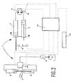
- Fig. 2 diagrammatically illustrates how the means according to the invention are applied onto a pump as shown in fig. 1.
- As shown on the drawings, a concrete pumping plant essentially comprises a pumping unit 1 fed from a
hopper 2, and a transport and delivery duct (not shown) to distribute the concrete on the working site. The pumping unit 1 consists of a pair ofconcrete pumping cylinders 3 alternately operated by a pair of hydraulic cylinders 4 controlled in the two directions by a backflowhydraulic pump 5 operated by aprime mover 6, and of a rocking S-valve 7 which connects the concrete transport and delivery duct to one of the twopumping cylinders 3, while the other cylinder draws concrete from thehopper 2. The S-valve 7 is alternately moved by a second pair ofhydraulic cylinders 8, fed by a hydraulic circuit withaccumulator 9 and controlled by a set ofsolenoid valves 10. By combining the movement of the S-valve 7 with the movement of thepumping cylinders 3, a concrete flow is generated (the concrete being either pumped, or drawn) and moves, in a practically continuous manner, through the concrete transport and delivery duct. - As already mentioned, the movement of the S-valve should be started with a certain advance in respect of the moment - detected by suitable stops 11 - in which the piston of the pumping
cylinder 3, feeding the concrete into the transport and delivery duct through the S-valve 7, reaches the top dead center. - According to the invention, the advance time is set by locating the
stops 11 in the position apt to guarantee the most efficient working with the highest number of pumping cycles per minute of the plant, and then delaying - by reducing said advance time - the starting movement of the 5-valve and the reversal of the backflowhydraulic pump 5 according to the actual number of pumping cycles per minute. - Preferably, said reduction of the advance time is controlled by electronic means which comprise a
microprocessor unit 12, into which are set the pumping cycles by apanel 13 and which receives the signals issued bysaid stops 11, detects and reckons the number of pumping cycles per minute through asensor 14, and controls both the movements of the S-valve 7 and the reversal of the backflowhydraulic pump 5, automatically adapting them to the number of pumping cycles per minute, on changing of the operating conditions. - According to the present invention, the concrete pumping plant is controlled as per the following flow diagram:
 which perfectly synthesizes the sequence of the operating steps.
- There is no need to underline that the present invention achieves the important result - never obtained up-to-date - to put the concrete pumping plants in conditions to always operate with an optimal advance of the starting movements of the S-valve and of the motion reversal of the pistons in the cylinders, in respect of the moment in which said pistons reach the top dead center, to the full advantage of a far more continuous and smoother working of the pumps (which lengthens the life thereof and reduces their stresses) and of an increasingly reduced energy consumption determined by the full use made of the working strokes of the pumping pistons.
Claims (2)
- Concrete pump (1) of the type comprising a pair of pumpingcylinders (3) alternat operating with respective pistons under the control of a backflow hydraulic pump (5) to draw concrete from a hopper (2) and feed it, by way of a rocking S-valve (7) into the transport and delivery duct - wherein said cylinders are provided at or near their top dead center, with stops (11) controlling the starting movements of the S-valve (7) with a predetermined advance time in respect of the moment in which said pistons reach their top dead centers and reverse their movement, characterized in that said stops (11) are located in the position for the most efficient working conditions of the pump at the highest number of puniping cycles per minute, and in that electronic means (12, 13, 14) are provided to set said advance time, by delaying the starting movement of the S-valve and the reversal of the backflow hydraulic pump (5) according to the actual number of pumping cycles per minute.
- Concrete pump as in claim 1), wherein said electronic means (12, 13, 14) comprise a microprocessor unit, into which are set the pumping cycles and which receives the signals issued by said stops (11), detects and reckons the number of pumping cycles per minute, and controls the movement of the S-valve (7) and the reversal of the backflow hydraulic pump (5).
Applications Claiming Priority (2)
| Application Number | Priority Date | Filing Date | Title |
|---|---|---|---|
| ITMI981572 | 1998-07-09 | ||
| IT98MI001572A ITMI981572A1 (en) | 1998-07-09 | 1998-07-09 | CONCRETE PUMP WITH MEANS OF REGULATION OF THE ADVANCE OF THE MOVEMENTS OF THE S-VALVE OF THE PUMPING GROUP WITH RESPECT TO |
Publications (2)
| Publication Number | Publication Date |
|---|---|
| EP0971126A1 EP0971126A1 (en) | 2000-01-12 |
| EP0971126B1 true EP0971126B1 (en) | 2006-05-03 |
Family
ID=11380404
Family Applications (1)
| Application Number | Title | Priority Date | Filing Date |
|---|---|---|---|
| EP99113573A Expired - Lifetime EP0971126B1 (en) | 1998-07-09 | 1999-07-08 | Actuation of the S-valve of a concrete pump prior to completion of piston stroke |
Country Status (8)
| Country | Link |
|---|---|
| EP (1) | EP0971126B1 (en) |
| AT (1) | ATE325272T1 (en) |
| CY (1) | CY1105103T1 (en) |
| DE (1) | DE69931106T2 (en) |
| DK (1) | DK0971126T3 (en) |
| ES (1) | ES2262272T3 (en) |
| IT (1) | ITMI981572A1 (en) |
| PT (1) | PT971126E (en) |
Family Cites Families (5)
| Publication number | Priority date | Publication date | Assignee | Title |
|---|---|---|---|---|
| US4533300A (en) * | 1979-06-11 | 1985-08-06 | Robert E. Westerlund | High pressure pumping apparatus for semi-fluid material |
| DE4035518C2 (en) * | 1990-11-08 | 1994-06-09 | Putzmeister Maschf | Method and arrangement for determining the volume flow of conveyed material transported by means of a piston-type nitrogen pump |
| DE4215403C2 (en) * | 1991-05-16 | 2000-10-19 | Mbt Holding Ag Zuerich | Double piston pump for pumping liquid materials, especially concrete or mortar |
| DE4127277A1 (en) * | 1991-08-17 | 1993-02-18 | Putzmeister Maschf | HYDRAULIC CONTROL DEVICE FOR A FUEL PUMP |
| ES2090741T3 (en) * | 1992-03-21 | 1996-10-16 | Schwing Gmbh F | PUMP FOR CONSISTENT MATERIALS. |
-
1998
- 1998-07-09 IT IT98MI001572A patent/ITMI981572A1/en unknown
-
1999
- 1999-07-08 DE DE69931106T patent/DE69931106T2/en not_active Expired - Lifetime
- 1999-07-08 EP EP99113573A patent/EP0971126B1/en not_active Expired - Lifetime
- 1999-07-08 DK DK99113573T patent/DK0971126T3/en active
- 1999-07-08 AT AT99113573T patent/ATE325272T1/en active
- 1999-07-08 PT PT99113573T patent/PT971126E/en unknown
- 1999-07-08 ES ES99113573T patent/ES2262272T3/en not_active Expired - Lifetime
-
2006
- 2006-07-21 CY CY20061101021T patent/CY1105103T1/en unknown
Also Published As
| Publication number | Publication date |
|---|---|
| DE69931106T2 (en) | 2006-11-16 |
| ITMI981572A1 (en) | 2000-01-09 |
| PT971126E (en) | 2006-09-29 |
| DK0971126T3 (en) | 2006-09-04 |
| ATE325272T1 (en) | 2006-06-15 |
| EP0971126A1 (en) | 2000-01-12 |
| DE69931106D1 (en) | 2006-06-08 |
| ES2262272T3 (en) | 2006-11-16 |
| CY1105103T1 (en) | 2009-11-04 |
Similar Documents
| Publication | Publication Date | Title |
|---|---|---|
| CA2355612C (en) | Device for continuous regulation of the gas flow rate processed by a reciprocating compressor | |
| EP3232057B1 (en) | Method for transmitting or conveying fluid or semi-fluid materials by means of a double piston pump and double piston pump therefor | |
| EP0481690A2 (en) | Method and apparatus for starting a displacer engine hydraulically | |
| US5634773A (en) | Superhigh pressure control system | |
| JP2005538299A (en) | Liquid-driven mechanical device and method of operation | |
| JP4806500B2 (en) | Apparatus and method for controlling discharge pressure of variable displacement hydraulic pump | |
| JP2000511612A (en) | Hydraulic control system for pump | |
| GR3021021T3 (en) | Pump for viscous material | |
| JP4129761B2 (en) | Operation controller for reciprocating viscous fluid pump | |
| EP0971126A1 (en) | Actuation of the S-valve of a concrete pump prior to completion of piston stroke | |
| EP0971127B1 (en) | Piston speed modulation for a concrete pump | |
| EP1059425A3 (en) | Pilot control valve for controlling a reciprocating pump | |
| AU2003273791A1 (en) | A reciprocating liquid pump for delivery of liquid fuel to a domestic burner device | |
| CN114439794A (en) | Mobile working machine, method for a mobile working machine and use | |
| JPH0633767B2 (en) | Slurry pump | |
| DE3479911D1 (en) | Hydraulic circuit for the control of reciprocating pistons pump | |
| EP1306550A1 (en) | Improved concrete pump with means to automatically adjust the working of the S-valve according to the type of concrete | |
| KR200152631Y1 (en) | Pressure intensifying system | |
| CN113847048A (en) | Multi-pump electric control cooperative tunneling machine cutter head driving servo control system and control method | |
| JPS6214386Y2 (en) | ||
| RU2215185C2 (en) | Variable capacity pump | |
| JP2000329102A (en) | Automatic pressure booster | |
| JPH10212728A (en) | Hydraulic circuit for construction machinery | |
| JPS5813753B2 (en) | Control device for pumps for pumping highly viscous substances | |
| CA2567445A1 (en) | Drive device for a dual-cylinder slurry pump and method for operating said pump |
Legal Events
| Date | Code | Title | Description |
|---|---|---|---|
| PUAI | Public reference made under article 153(3) epc to a published international application that has entered the european phase |
Free format text: ORIGINAL CODE: 0009012 |
|
| AK | Designated contracting states |
Kind code of ref document: A1 Designated state(s): AT BE CH CY DE DK ES FI FR GB GR IE IT LI LU MC NL PT SE |
|
| AX | Request for extension of the european patent |
Free format text: AL;LT;LV;MK;RO;SI |
|
| AKX | Designation fees paid | ||
| 17P | Request for examination filed |
Effective date: 20000712 |
|
| RBV | Designated contracting states (corrected) |
Designated state(s): AT BE CH CY DE DK ES FI FR GB GR IE IT LI LU MC NL PT SE |
|
| 17Q | First examination report despatched |
Effective date: 20040116 |
|
| RAP1 | Party data changed (applicant data changed or rights of an application transferred) |
Owner name: COMPAGNIA ITALIANA FORME ACCIAIO S.P.A. |
|
| GRAP | Despatch of communication of intention to grant a patent |
Free format text: ORIGINAL CODE: EPIDOSNIGR1 |
|
| GRAS | Grant fee paid |
Free format text: ORIGINAL CODE: EPIDOSNIGR3 |
|
| GRAA | (expected) grant |
Free format text: ORIGINAL CODE: 0009210 |
|
| AK | Designated contracting states |
Kind code of ref document: B1 Designated state(s): AT BE CH CY DE DK ES FI FR GB GR IE IT LI LU MC NL PT SE |
|
| REG | Reference to a national code |
Ref country code: GB Ref legal event code: FG4D |
|
| REG | Reference to a national code |
Ref country code: CH Ref legal event code: EP |
|
| REF | Corresponds to: |
Ref document number: 69931106 Country of ref document: DE Date of ref document: 20060608 Kind code of ref document: P |
|
| REG | Reference to a national code |
Ref country code: IE Ref legal event code: FG4D |
|
| REG | Reference to a national code |
Ref country code: CH Ref legal event code: NV Representative=s name: BOVARD AG PATENTANWAELTE |
|
| REG | Reference to a national code |
Ref country code: SE Ref legal event code: TRGR |
|
| PG25 | Lapsed in a contracting state [announced via postgrant information from national office to epo] |
Ref country code: MC Free format text: LAPSE BECAUSE OF NON-PAYMENT OF DUE FEES Effective date: 20060731 |
|
| REG | Reference to a national code |
Ref country code: DK Ref legal event code: T3 |
|
| REG | Reference to a national code |
Ref country code: GR Ref legal event code: EP Ref document number: 20060402380 Country of ref document: GR |
|
| REG | Reference to a national code |
Ref country code: PT Ref legal event code: SC4A Effective date: 20060727 |
|
| REG | Reference to a national code |
Ref country code: ES Ref legal event code: FG2A Ref document number: 2262272 Country of ref document: ES Kind code of ref document: T3 |
|
| ET | Fr: translation filed | ||
| PLBE | No opposition filed within time limit |
Free format text: ORIGINAL CODE: 0009261 |
|
| STAA | Information on the status of an ep patent application or granted ep patent |
Free format text: STATUS: NO OPPOSITION FILED WITHIN TIME LIMIT |
|
| 26N | No opposition filed |
Effective date: 20070206 |
|
| PGFP | Annual fee paid to national office [announced via postgrant information from national office to epo] |
Ref country code: CY Payment date: 20100614 Year of fee payment: 12 |
|
| REG | Reference to a national code |
Ref country code: CH Ref legal event code: PFA Owner name: COMPAGNIA ITALIANA FORME ACCIAIO S.P.A. Free format text: COMPAGNIA ITALIANA FORME ACCIAIO S.P.A.#VIA STATI UNITI D'AMERICA 26.#20030 SENAGO (MILANO) (IT) -TRANSFER TO- COMPAGNIA ITALIANA FORME ACCIAIO S.P.A.#VIA STATI UNITI D'AMERICA 26.#20030 SENAGO (MILANO) (IT) |
|
| PGFP | Annual fee paid to national office [announced via postgrant information from national office to epo] |
Ref country code: LU Payment date: 20110725 Year of fee payment: 13 |
|
| PG25 | Lapsed in a contracting state [announced via postgrant information from national office to epo] |
Ref country code: CY Free format text: LAPSE BECAUSE OF NON-PAYMENT OF DUE FEES Effective date: 20120708 |
|
| PGFP | Annual fee paid to national office [announced via postgrant information from national office to epo] |
Ref country code: GR Payment date: 20130729 Year of fee payment: 15 Ref country code: IE Payment date: 20130726 Year of fee payment: 15 Ref country code: SE Payment date: 20130719 Year of fee payment: 15 Ref country code: FI Payment date: 20130711 Year of fee payment: 15 Ref country code: PT Payment date: 20130108 Year of fee payment: 15 Ref country code: DK Payment date: 20130719 Year of fee payment: 15 |
|
| PGFP | Annual fee paid to national office [announced via postgrant information from national office to epo] |
Ref country code: GB Payment date: 20130719 Year of fee payment: 15 |
|
| PG25 | Lapsed in a contracting state [announced via postgrant information from national office to epo] |
Ref country code: LU Free format text: LAPSE BECAUSE OF NON-PAYMENT OF DUE FEES Effective date: 20120708 |
|
| PGFP | Annual fee paid to national office [announced via postgrant information from national office to epo] |
Ref country code: NL Payment date: 20140721 Year of fee payment: 16 |
|
| PGFP | Annual fee paid to national office [announced via postgrant information from national office to epo] |
Ref country code: ES Payment date: 20140728 Year of fee payment: 16 Ref country code: FR Payment date: 20140721 Year of fee payment: 16 |
|
| REG | Reference to a national code |
Ref country code: PT Ref legal event code: MM4A Free format text: LAPSE DUE TO NON-PAYMENT OF FEES Effective date: 20150108 |
|
| PGFP | Annual fee paid to national office [announced via postgrant information from national office to epo] |
Ref country code: BE Payment date: 20140722 Year of fee payment: 16 |
|
| REG | Reference to a national code |
Ref country code: DK Ref legal event code: EBP Effective date: 20140731 |
|
| REG | Reference to a national code |
Ref country code: SE Ref legal event code: EUG |
|
| GBPC | Gb: european patent ceased through non-payment of renewal fee |
Effective date: 20140708 |
|
| REG | Reference to a national code |
Ref country code: GR Ref legal event code: ML Ref document number: 20060402380 Country of ref document: GR Effective date: 20150204 |
|
| REG | Reference to a national code |
Ref country code: IE Ref legal event code: MM4A |
|
| PG25 | Lapsed in a contracting state [announced via postgrant information from national office to epo] |
Ref country code: PT Free format text: LAPSE BECAUSE OF NON-PAYMENT OF DUE FEES Effective date: 20150108 Ref country code: FI Free format text: LAPSE BECAUSE OF NON-PAYMENT OF DUE FEES Effective date: 20140708 |
|
| PG25 | Lapsed in a contracting state [announced via postgrant information from national office to epo] |
Ref country code: SE Free format text: LAPSE BECAUSE OF NON-PAYMENT OF DUE FEES Effective date: 20140709 Ref country code: GR Free format text: LAPSE BECAUSE OF NON-PAYMENT OF DUE FEES Effective date: 20150204 Ref country code: GB Free format text: LAPSE BECAUSE OF NON-PAYMENT OF DUE FEES Effective date: 20140708 |
|
| PG25 | Lapsed in a contracting state [announced via postgrant information from national office to epo] |
Ref country code: DK Free format text: LAPSE BECAUSE OF NON-PAYMENT OF DUE FEES Effective date: 20140731 |
|
| PG25 | Lapsed in a contracting state [announced via postgrant information from national office to epo] |
Ref country code: IE Free format text: LAPSE BECAUSE OF NON-PAYMENT OF DUE FEES Effective date: 20140708 |
|
| REG | Reference to a national code |
Ref country code: NL Ref legal event code: MM Effective date: 20150801 |
|
| REG | Reference to a national code |
Ref country code: FR Ref legal event code: ST Effective date: 20160331 |
|
| PG25 | Lapsed in a contracting state [announced via postgrant information from national office to epo] |
Ref country code: FR Free format text: LAPSE BECAUSE OF NON-PAYMENT OF DUE FEES Effective date: 20150731 Ref country code: NL Free format text: LAPSE BECAUSE OF NON-PAYMENT OF DUE FEES Effective date: 20150801 |
|
| REG | Reference to a national code |
Ref country code: ES Ref legal event code: FD2A Effective date: 20160826 |
|
| PGFP | Annual fee paid to national office [announced via postgrant information from national office to epo] |
Ref country code: CH Payment date: 20160721 Year of fee payment: 18 |
|
| PG25 | Lapsed in a contracting state [announced via postgrant information from national office to epo] |
Ref country code: ES Free format text: LAPSE BECAUSE OF NON-PAYMENT OF DUE FEES Effective date: 20150709 |
|
| PGFP | Annual fee paid to national office [announced via postgrant information from national office to epo] |
Ref country code: AT Payment date: 20160721 Year of fee payment: 18 |
|
| PG25 | Lapsed in a contracting state [announced via postgrant information from national office to epo] |
Ref country code: BE Free format text: LAPSE BECAUSE OF NON-PAYMENT OF DUE FEES Effective date: 20150731 |
|
| REG | Reference to a national code |
Ref country code: CH Ref legal event code: PL |
|
| REG | Reference to a national code |
Ref country code: AT Ref legal event code: MM01 Ref document number: 325272 Country of ref document: AT Kind code of ref document: T Effective date: 20170708 |
|
| PG25 | Lapsed in a contracting state [announced via postgrant information from national office to epo] |
Ref country code: CH Free format text: LAPSE BECAUSE OF NON-PAYMENT OF DUE FEES Effective date: 20170731 Ref country code: LI Free format text: LAPSE BECAUSE OF NON-PAYMENT OF DUE FEES Effective date: 20170731 |
|
| PG25 | Lapsed in a contracting state [announced via postgrant information from national office to epo] |
Ref country code: AT Free format text: LAPSE BECAUSE OF NON-PAYMENT OF DUE FEES Effective date: 20170708 |
|
| PGFP | Annual fee paid to national office [announced via postgrant information from national office to epo] |
Ref country code: DE Payment date: 20180723 Year of fee payment: 20 Ref country code: IT Payment date: 20180717 Year of fee payment: 20 |
|
| REG | Reference to a national code |
Ref country code: DE Ref legal event code: R071 Ref document number: 69931106 Country of ref document: DE |